US11222539B2 - Method for early warning of vehicle collision, on-board terminal and server - Google Patents
Method for early warning of vehicle collision, on-board terminal and server Download PDFInfo
- Publication number
- US11222539B2 US11222539B2 US16/836,218 US202016836218A US11222539B2 US 11222539 B2 US11222539 B2 US 11222539B2 US 202016836218 A US202016836218 A US 202016836218A US 11222539 B2 US11222539 B2 US 11222539B2
- Authority
- US
- United States
- Prior art keywords
- vehicle
- distance
- early warning
- sensing data
- information
- Prior art date
- Legal status (The legal status is an assumption and is not a legal conclusion. Google has not performed a legal analysis and makes no representation as to the accuracy of the status listed.)
- Expired - Fee Related
Links
Images


Classifications
-
- G—PHYSICS
- G08—SIGNALLING
- G08G—TRAFFIC CONTROL SYSTEMS
- G08G1/00—Traffic control systems for road vehicles
- G08G1/16—Anti-collision systems
-
- G—PHYSICS
- G08—SIGNALLING
- G08G—TRAFFIC CONTROL SYSTEMS
- G08G1/00—Traffic control systems for road vehicles
- G08G1/16—Anti-collision systems
- G08G1/166—Anti-collision systems for active traffic, e.g. moving vehicles, pedestrians, bikes
-
- G—PHYSICS
- G08—SIGNALLING
- G08B—SIGNALLING SYSTEMS, e.g. PERSONAL CALLING SYSTEMS; ORDER TELEGRAPHS; ALARM SYSTEMS
- G08B21/00—Alarms responsive to a single specified undesired or abnormal condition and not otherwise provided for
- G08B21/18—Status alarms
- G08B21/182—Level alarms, e.g. alarms responsive to variables exceeding a threshold
-
- G—PHYSICS
- G08—SIGNALLING
- G08B—SIGNALLING SYSTEMS, e.g. PERSONAL CALLING SYSTEMS; ORDER TELEGRAPHS; ALARM SYSTEMS
- G08B7/00—Signalling systems according to two or more of groups G08B3/00 - G08B6/00
- G08B7/06—Signalling systems according to two or more of groups G08B3/00 - G08B6/00 using electric transmission, e.g. involving audible and visible signalling through the use of sound and light sources
-
- G—PHYSICS
- G08—SIGNALLING
- G08G—TRAFFIC CONTROL SYSTEMS
- G08G1/00—Traffic control systems for road vehicles
- G08G1/16—Anti-collision systems
- G08G1/164—Centralised systems, e.g. external to vehicles
-
- G—PHYSICS
- G08—SIGNALLING
- G08G—TRAFFIC CONTROL SYSTEMS
- G08G1/00—Traffic control systems for road vehicles
- G08G1/16—Anti-collision systems
- G08G1/165—Anti-collision systems for passive traffic, e.g. including static obstacles, trees
Definitions
- the present disclosure relates to a field of assisted driving technique, and in particular to a method for early warning of vehicle collision, an on-board terminal, and a server.
- the present disclosure provides a method for early warning of vehicle collision applied to a first on-board terminal, wherein the first on-board terminal is configured in a first vehicle.
- the method comprises: acquiring distance-sensing data detected by sensors configured in the first vehicle as first distance-sensing data; determining whether there is an obstacle within an early warning range of the first vehicle based on the first distance-sensing data; acquiring distance-sensing data transmitted by on-board terminals of other vehicles within a communication range of the first vehicle as second distance-sensing data when it is determined that there is an obstacle in the early warning range of the first vehicle; determining whether the obstacle is a vehicle based on a matching result of the first distance-sensing data and the second distance-sensing data; and outputting a first early warning information when it is determined that the obstacle is a vehicle.
- the method further comprises: acquiring speed information and orientation information of the first vehicle; determining the early warning range of the first vehicle according to the speed information and the orientation information; or determining the early warning range of the first vehicle according to the speed information, the orientation information, and vehicle type information of the first vehicle, wherein the determining whether there is an obstacle within an early warning range of the first vehicle based on the first distance-sensing data comprises: determining a distance between the obstacle and the first vehicle based on the first distance-sensing data; determining whether the obstacle is within the early warning range based on the distance between the obstacle and the first vehicle.
- the outputting a first early warning information comprises: determining an early warning level according to the distance between the obstacle and the first vehicle; outputting a first early warning information which includes the early warning level; or determining a safe speed of the first vehicle according to the distance between the obstacle and the first vehicle and a reaction time; outputting a first early warning information which includes the safe speed.
- the acquiring distance-sensing data transmitted by on-board terminals of other vehicles within a communication range of the first vehicle as second distance-sensing data comprises: establishing a wireless connection with a second on-board terminal, wherein the second on-board terminal is configured in a second vehicle, and the second vehicle is other vehicle within the communication range of the first vehicle; receiving distance-sensing data detected by sensors configured in the second vehicle and transmitted by the second on-board terminal as the second distance-sensing data.
- the method further comprises: determining, for first distance-sensing data and second distance-sensing data that are successfully matched, location information of a vehicle corresponding to the second distance-sensing data according to an identifier of a first sensor corresponding to the first distance-sensing data and an identifier of a second sensor corresponding to the second distance-sensing data, the outputting a first early warning information comprises: outputting a first early warning information which includes the location information.
- the establishing a wireless connection with a second on-board terminal comprises: establishing a wireless connection with the second on-board terminal configured in the second vehicle through wireless transceivers configured in the first vehicle and the second vehicle; or establishing a Bluetooth connection with the second on-board terminal.
- the establishing a wireless connection with a second on-board terminal comprises: searching, by means of broadcasting, for an on-board terminal of other vehicle within the communication range of the first on-board terminal as the second on-board terminal; if an on-board terminal is found as the second on-board terminal, establishing a wireless connection with the second on-board terminal; if an on-board terminal is not found, stopping the broadcasting, and establishing a wireless connection with a second on-board terminal that transmits a connection request when receiving the connection request of the second on-board terminal.
- the method further comprises: acquiring positioning information of the first vehicle; transmitting the positioning information and the early warning range of the first vehicle to a server, so that the server determines whether there are mutually intersected early warning ranges based on received positioning information and early warning ranges transmitted by on-board terminals, and if so, transmits a second early warning information to an on-board terminal within the mutually intersected early warning ranges.
- the present disclosure further provides a method for early earning of vehicle collision applied to a server.
- the method comprises: acquiring vehicle data transmitted by a plurality of on-board terminals, the vehicle data including positioning information of vehicles, driving speed of vehicles, and orientation information of vehicles; determining an early warning range of a vehicle to which each of the plurality of on-board terminals belongs based on the vehicle data; determining whether there are mutually intersected early warning ranges in early warning ranges of the plurality of on-board terminals; transmitting a third early warning information to an on-board terminal within the mutually intersected early warning ranges when there are mutually intersected early warning ranges.
- the method further comprises: predicting, for the on-board terminal within the mutually intersected early warning ranges, a movement trajectory of a vehicle to which the on-board terminal belongs based on vehicle data transmitted by the on-board terminal, the movement trajectory including time information and position information of a plurality of trajectory points; determining trajectory points with both same time information and same position information as matched trajectory points by matching the movement trajectory.
- the transmitting a third early warning information to an on-board terminal within the mutually intersected early warning ranges comprises: transmitting the third early warning information to an on-board terminal corresponding to the matched trajectory points, wherein the third early warning information includes time information and position information of the matched trajectory points.
- the present disclosure further provides an on-board terminal comprising a memory, a processor, and a computer program stored on the memory and executable on the processor, the processor implementing the method for early warning of vehicle collision applied to a first on-board terminal when the processor executes the program.
- the present disclosure further provides a server comprising a memory, a processor, and a computer program stored on the memory and executable on the processor, the processor implementing the method for early warning of vehicle collision applied to a server, when the processor executes the program.
- the present disclosure further provides an on-board terminal comprising: a first processor, a plurality of second processors, and a wireless transceiver, wherein each second processor is connected to a sensor, and wherein the wireless transceiver is configured to communicate with other on-board terminals; each second processor is configured to transmit first distance-sensing data detected by a sensor connected to itself to the first processor; the first processor is configured to determine whether there is an obstacle within an early warning range of the on-board terminal based on the received first distance-sensing data; acquire, through the wireless transceiver, distance-sensing data transmitted by on-board terminals of other vehicles as second distance-sensing data when it is determined that there is an obstacle; determine whether the obstacle is a vehicle based on a matching result of the first distance-sensing data and the second distance-sensing data; output a first early warning information when it is determined that the obstacle is a vehicle.
- the on-board terminal further comprises a positioner and a speed detector; the positioner being configured to obtain orientation information of a vehicle to which it belongs, and transmit the orientation information to the first processor; the speed detector being configured to collect speed information of a vehicle to which it belongs, and transmit the speed information to the first processor; the first processor being further configured to determine an early warning range of a vehicle to which it belongs according to the speed information and the orientation information; or determine the early warning range of the vehicle to which it belongs according to the speed information, the orientation information, and vehicle type information of the vehicle to which it belongs.
- FIG. 1 is a schematic flowchart of a method for early warning of vehicle collision applied to an on-board terminal provided by the embodiments of the present disclosure
- FIG. 2 is a schematic diagram of configuration positions of sensors provided by the embodiments of the present disclosure.
- FIG. 3 is a schematic diagram of an early warning range provided by the embodiments of the present disclosure.
- FIG. 4 is a schematic diagram of vehicle location provided by the embodiments of the present disclosure.
- FIG. 5 is a schematic flowchart of a method for early warning of vehicle collision applied to a server provided by the embodiments of the present disclosure
- FIG. 6 is a schematic diagram of positioning an early warning range provided by the embodiments of the present disclosure.
- FIG. 7 is a schematic diagram of a storage structure of vehicle data provided by the embodiments of the present disclosure.
- FIG. 8 is a schematic structural diagram of an on-board terminal provided by the embodiments of the present disclosure.
- FIG. 9 is a schematic structural diagram of a slave microcomputer module provided by the embodiments of the present disclosure.
- FIG. 10 is a schematic diagram of interactions between an on-board terminal and a server provided by the embodiments of the present disclosure.
- FIG. 11 is a schematic block diagram of an on-board terminal provided by the embodiments of the present disclosure.
- FIG. 12 is a schematic block diagram of a server provided by the embodiments of the present disclosure.
- FIG. 13 is another schematic structural diagram of an on-board terminal provided by the embodiments of the present disclosure.
- the present disclosure provides a method for early warning of vehicle collision applied to an on-board terminal, a method for early warning of vehicle collision applied to a server, an on-board terminal and a server to perform early warning of vehicle collision, thereby achieving functions of assisted driving.
- an execution body is referred to as a first on-board terminal
- a vehicle to which the first on-board terminal belongs is referred to as a first vehicle.
- the method for early warning of vehicle collision applied to an on-board terminal provided by the present disclosure, if there is an obstacle in an early warning range of the vehicle, distance-sensing data of the vehicle itself is matched with distance-sensing data of other vehicles. Whether the obstacle is a vehicle or not is determined based on a matching result, and a first early warning information is output when it is determined that the obstacle is a vehicle. It can be seen that in the present disclosure, early warning is performed only when the obstacle is a vehicle, which reduces a false-positive rate of early warning.
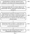
- FIG. 1 is a schematic flowchart of a method for early warning of vehicle collision applied to an on-board terminal provided by the embodiments of the present disclosure.
- step S 101 distance-sensing data detected by sensors configured in a first vehicle is acquired as first distance-sensing data.
- one or more sensors may be configured in a vehicle, and the specific number is not limited. If a plurality of sensors are configured in the vehicle, distance-sensing data in a plurality of directions may be detected, and more accurate early warning of vehicle collision may be performed based on the distance-sensing data in the plurality of directions.
- FIG. 2 is a schematic diagram of configuration positions of sensors provided by the embodiments of the present disclosure.
- a total of 8 sensors may be arranged at the front, back, left, and right of the vehicle, and these sensors may monitor whether there is an obstacle in 8 directions around the vehicle. If there is an obstacle, distance-sensing data of the obstacle and the vehicle may be further detected.
- the distance-sensing data detected by the sensors configured in the first vehicle is referred to as the first distance-sensing data.
- step S 102 whether there is an obstacle in an early warning range of the first vehicle is determined based on the first distance-sensing data.
- the early warning range represents a safe distance for the vehicle to travel. If the obstacle is outside the early warning range, it indicates that a risk of collision with the vehicle is small, and the vehicle can drive safely. If the obstacle is within the early warning range, it indicates that a risk of collision with the vehicle is large, and the driver should be alert or make corresponding driving decisions to avoid a collision.
- S 102 may include: determining a distance between the obstacle and the first vehicle based on the first distance-sensing data; and determining whether the obstacle is within the early warning range based on the distance between the obstacle and the first vehicle.
- the early warning range may be a fixed range. For example, taking the vehicle as a center point, a range within a distance of 10 meters from the vehicle may be set as the early warning range, in which the distance may be set according to actual conditions, such as 5 meters, 15 meters and so on, and the specific value is not limited.
- the early warning range may be a circular range, a rectangular range, an elliptical range, etc., and the specific shape of the early warning range is not limited.
- the early warning range may be a dynamic range, for example, speed information and orientation information of the first vehicle may be acquired; in one embodiment, the early warning range of the first vehicle may be determined according to the speed information and the orientation information.
- the vehicle may be configured with MPU6000 (a 6-axis motion processing component), and the MPU6000 may collect acceleration data and direction data of the vehicle, so that the speed information and the orientation information of the vehicle may be obtained.
- MPU6000 a 6-axis motion processing component
- other acquisition detectors may be configured in the vehicle to detect the speed information and the orientation information of the vehicle, which are not specifically limited.
- FIG. 3 is a schematic diagram of an early warning range provided by the embodiments of the present disclosure, where the early warning range is a rectangle.
- the size of the rectangle is dynamically variable
- the length of the rectangle that is, the value of a
- the width of the rectangle that is, the value of b
- the vehicle turns, a direction of the vehicle may be re-determined based on direction data detected by the MPU6000, and then the early warning range of the vehicle is re-determined.
- the early warning range of the first vehicle may be determined according to the speed information, the orientation information, and vehicle type information of the first vehicle.
- the vehicle type information is also used as a factor to be considered for a safe distance (i.e., the early warning range) of the vehicle.
- the vehicle type information may be obtained by pre-registration.
- a dynamic early warning range is formed by combining real-time speed information, the orientation information, and the pre-obtained vehicle type information of the vehicle.
- the early warning range of the vehicle is dynamically determined according to actual conditions of the vehicle, and the determined early warning range is more reasonable.
- step S 103 when it is determined that there is an obstacle in the early warning range of the first vehicle, distance-sensing data transmitted by on-board terminals of other vehicles within a communication range of the first vehicle is obtained as second distance-sensing data.
- the other vehicles may be one vehicle or a plurality of vehicles.
- step S 103 may include: establishing a wireless connection with a second on-board terminal; where the second on-board terminal is configured in a second vehicle, and the second vehicle is other vehicle within the communication range of the first vehicle; receiving distance-sensing data detected by sensors configured in the second vehicle and transmitted by the second on-board terminal as the second distance-sensing data.
- the second vehicle other vehicles within the communication range of the first vehicle will be referred to as the second vehicle
- on-board terminals configured in the second vehicle will be referred to as the second on-board terminal
- distance-sensing data detected by sensors configured in the second vehicle will be referred to as the second distance-sensing data.
- the first vehicle may continuously establish wireless connection with on-board terminals of other vehicles within its communication range, and acquire the second distance-sensing data when it is determined that there is an obstacle within the early warning range of the first vehicle.
- the first vehicle may establish wireless connections with on-board terminals of other vehicles within its communication range only when it is determined that there is an obstacle within its own early warning range. In this way, communication resources may be saved compared with continuous connections.
- the establishing a wireless connection with a second on-board terminal may comprise: establishing a wireless connection with the second on-board terminal configured in the second vehicle through wireless transceivers configured in the first vehicle and the second vehicle; or, establishing a Bluetooth connection with the second on-board terminal.
- data may be transmitted between on-board terminals through Bluetooth modules in vehicles, which eliminates the need to configure other communication devices and thus saves costs.
- wireless transceivers may be configured in vehicles, and data transmission between on-board terminals may be realized through the wireless transceivers.
- independent communication channels are formed between the wireless transceivers, which are less affected by other signals; in a second aspect, the wireless transceivers do not need to be paired and communicate directly based on an agreed protocol.
- the establishing a wireless connection with a second on-board terminal may comprise: searching, by means of broadcasting, for an on-board terminal of other vehicle within the communication range of the first on-board terminal as the second on-board terminal; if an on-board terminal is found as the second on-board terminal, establishing a wireless connection with the second on-board terminal; if an on-board terminal is not found, stopping the broadcasting, and establishing a wireless connection with a second on-board terminal that transmits a connection request when receiving the connection request of the second on-board terminal.
- the on-board terminal may have two modes, an active search mode and a passive discovery mode.
- an active search mode it is possible that they cannot search each other, and in this case, one on-board terminal may be switched to the passive discovery mode, which can reduce a situation that both on-board terminals search actively but cannot discovery each other.
- data transmission between on-board terminals may be achieved through wireless transceivers configured in vehicles.
- the active search mode and the passive discovery mode may be configured in the wireless transceivers. If the active search mode is enabled by a wireless transceiver, a small regional hotspot may be formed; and if the passive discovery mode is enabled by the wireless transceiver, it waits for other wireless transceivers to establish a connection with it.
- step S 104 whether the obstacle is a vehicle is determined based on a matching result of the first distance-sensing data and the second distance-sensing data. And, in step S 105 , if it is determined that the obstacle is a vehicle, a first early warning information is output.
- the early warning information output in S 105 is referred to as the first early warning information.
- the form of the early warning information may be: output-text prompt information, voice prompt information, light flashing, buzzing sound, etc., and the specific form is not limited.
- first”, “second” and similar words used in this disclosure do not indicate any order, quantity, or importance, but are only used to distinguish different components, such as the first early warning information, and a second early warning information, a third early warning information, etc. described below.
- the outputting a first early warning information may comprise: determining an early warning level according to a distance between the obstacle and the first vehicle; outputting a first early warning information which includes the early warning level.
- a correspondence relationship between the distance of the obstacle and the early warning level may be set in advance, and the smaller the distance, the higher the level.
- the distance between the vehicle and the obstacle may be determined, and then the early warning level may be determined based on the corresponding relationship, where the early warning level may prompt the driver to a safety risk situation.
- the early warning level is carried in the output early warning information, which is richer in content.
- the early warning manner is a beep
- the higher the early warning level the louder the beep.
- different types of beeps may be used for different early warning levels.
- the early warning manner is light flashing
- the higher the early warning level the greater the light intensity.
- different types of light flashing may be used for different early warning levels.
- the specific early warning manner is not limited.
- the outputting a first early warning information may comprise: determining a safe speed of the first vehicle according to the distance between the obstacle and the first vehicle and a reaction time; outputting a first early warning information which includes the safe speed.
- the reaction time may be understood as a time period required for a driver to take a brake or other measures to avoid a collision.
- the distance between the vehicle and the obstacle may be determined.
- a quotient of the distance and the reaction time may be calculated as the safe speed of the first vehicle.
- the safe speed is carried in the output early warning information to prompt the user to drive within the safe speed range.
- a plurality of first sensors are respectively disposed at a plurality of preset positions of the first vehicle, and a plurality of second sensors are respectively disposed at a plurality of preset positions of the second vehicle, for example, as shown in FIG. 2 .
- the acquiring distance-sensing data detected by sensors configured in the first vehicle may comprise: receiving a first sensing message transmitted by each of the plurality of first sensors, the first sensing message including an identifier of the first sensor and its corresponding first distance-sensing data.
- first sensing messages respectively transmitted by the eight first sensors will be received, and each sensing message includes an identifier of a first sensor and first distance-sensing data.
- the receiving distance-sensing data detected by sensors configured in the second vehicle and transmitted by the second on-board terminal may comprise: receiving a second sensing message transmitted by the second on-board terminal, the second sensing message including an identifier of each of the plurality of second sensors and its corresponding second distance-sensing data.
- the determining whether the obstacle is a vehicle may comprise: determining whether there are matched first distance-sensing data and second distance-sensing data; if so, determining that the obstacle is a vehicle.
- first distance-sensing data indicate that there is an obstacle at a distance of 5 m from the first vehicle
- the second distance-sensing data indicates that there is an obstacle at a distance of 5 m from the second vehicle
- the method for early warning of vehicle collision applied to the first on-board terminal further comprises: determining, for first distance-sensing data and second distance-sensing data that are successfully matched, location information of a vehicle corresponding to the second distance-sensing data according to an identifier of a first sensor corresponding to the first distance-sensing data and an identifier of a second sensor corresponding to the second distance-sensing data.
- the location information represents a location of another vehicle being an obstacle relative to the current first vehicle.
- the outputting a first early warning information further comprises: outputting a first early warning information which includes the location information.
- sensors are configured at a plurality of preset positions of the vehicle, and distance-sensing data detected by different sensors may be distinguished by using identifiers of the sensors. It is assumed that the identifiers of the sensor are ⁇ circle around ( 1 ) ⁇ - ⁇ circle around ( 8 ) ⁇ in FIG. 2 .
- FIG. 4 is a schematic diagram of vehicle location provided by the embodiments of the present disclosure. As shown in FIG. 4 , the second vehicle is located in front right of the first vehicle.
- the early warning information output in S 105 may include location information.
- the output early warning information may be “Please note that a collision with a vehicle in front right may occur”, or other similar information, so as to prompt the user more accurately to avoid vehicles in front right and thus achieve a more accurate early warning.
- the output early warning information may further include driving recommendations for the driver, for example, “Please note that a collision with a vehicle in front right may occur. Please turn left”, etc., or other similar information.
- the distance-sensing data of the vehicle itself is matched with distance-sensing data of other vehicles, and whether the obstacle is a vehicle is determined based on a matching result; if so, a first early warning information is output.
- the obstacle may be a fixed obstacle such as a roadside stone, and for this obstacle, the driver may keep an original driving direction and driving speed to pass safely without a possibility of collision.
- early warning of collision to this obstacle should not be performed to avoid unnecessary early warning of danger.
- a GPS Global Positioning System
- the early warning range may be a fixed range or a dynamic range.
- the on-board terminal may transmit the positioning information and the early warning range to the server in a timing transmission manner or in an interrupted response transmission manner via the 3G (the 3rd Generation) or 4G (the 4th Generation) network.
- respective on-board terminals transmit positioning information and early warning ranges of vehicles to which they belong to the server, and the server performs overall early warning, which provides a more timely early warning from a global perspective compared with a single on-board terminal's early warning scheme.
- FIG. 5 is a schematic flowchart of a method for early warning of vehicle collision applied to a server according to the embodiments of the present disclosure.
- step S 501 vehicle data transmitted by a plurality of on-board terminals is acquired, the vehicle data including positioning information of vehicles, driving speed of vehicles, and orientation information of vehicles.
- GPSs Global Positioning Systems
- the MPU6000s may also be configured in the vehicles, and acceleration data and direction data of the vehicles may be detected by the MPU6000s. In this way, the driving speed of the vehicles and the orientation information of the vehicles may be obtained.
- other acquisition detectors may be configured in the vehicles to detect the vehicles' driving speed and orientation information, which is not specifically limited.
- Respective on-board terminals transmit vehicle data of vehicles to which they belong to the server.
- an on-board terminal may transmit vehicle data to the server in a timing transmission manner or in an interrupted response transmission manner via a 3G (the 3rd Generation) or 4G (the 4th Generation) network.
- 3G the 3rd Generation
- 4G the 4th Generation
- step S 502 an early warning range of a vehicle to which each of the plurality of on-board terminals belongs is determined based on the vehicle data.
- the early warning range may be a fixed range.
- a range within a distance of 10 meters from the vehicle may be set as the early warning range, in which the distance may be set according to actual conditions, such as 5 meters and 15 meters, and the specific value is not limited.
- the early warning range may be a circular range, a rectangular range, an elliptical range, etc., and the specific shape of the early warning range is not limited.
- the early warning range may be a dynamic range.
- the early warning range of the vehicle may be determined according to the driving speed of the vehicle and the orientation information of the vehicle acquired in S 501 .
- the early warning range of the vehicle may be determined according to the driving speed of the vehicle and the orientation information of the vehicle acquired in S 501 , and vehicle type information of the vehicle.
- vehicle type information is also used as a factor to be considered for a safe distance (i.e., the early warning range) of a vehicle.
- the vehicle type information may be obtained by pre-registration.
- a dynamic early warning range is formed by combining real-time speed information, the orientation information, and the pre-obtained vehicle type information of the vehicle.
- the early warning range of the vehicle is dynamically determined according to actual conditions of the vehicle, and the determined early warning range is more reasonable.
- FIG. 6 is a schematic diagram of positioning an early warning range provided by the embodiments of the present disclosure.
- the positioning information of the vehicle may be considered as a geographical location of the center point of the vehicle, and geographical location information of the early warning range may be determined according to the positioning information.
- it may be understood as determining the early warning range in an electronic map, and then whether there are mutually intersected early warning ranges is decided.
- step S 503 whether there are mutually intersected early warning ranges in early warning ranges of the plurality of on-board terminals is determined. And, in step S 504 , in the case that there are mutually intersected early warning ranges, a third early warning information is transmitted to an on-board terminal within the mutually intersected early warning ranges.
- the early warning information in S 503 is referred to as the third early warning information.
- the server may: determine a distance between vehicles based on vehicle data, and determine an early warning level based on the distance between the vehicles; output a first early warning information which includes the early warning level.
- a safe speed of the vehicles may be determined according to the distance between the vehicles and a reaction time.
- the third early warning information includes the safe speed is output.
- the reaction time may be understood as a time period required for a driver to take a brake or other measures to avoid a collision.
- a quotient of the distance between the vehicles and the reaction time may be calculated as the safe speed of the vehicles.
- the safe speed is carried in the output early warning information to prompt the user to drive within the safe speed range.
- the server may predict a movement trajectory of a vehicle based on received vehicle data, and determine whether the vehicle is likely to collide based on the movement trajectory, and if so, further determine a time and a location of the collision (the time information and the position information of the matched trajectory points). In this way, a user may be more accurately prompted to avoid vehicles that may collide with, thereby realizing a more accurate early warning.
- the server may analyze and predict a collision risk of vehicles after a period of time in the future.
- the server may generate driving recommendation information for the user according to the time information and/or the position information of the matched trajectory points, and the third early warning information may further include the driving recommendation information.
- the driving recommendation information may be “Turn left”, etc., which is no longer listed one by one.
- the server may provide different driving recommendation information for different on-board terminals.
- FIG. 7 is a schematic diagram of a storage structure of vehicle data provided by the embodiments of the present disclosure.
- vehicle data of different provinces (Province 1, City 2 . . . province m, where m is a positive integer) are stored separately, and vehicle data of different cities in a same province (City 11, City 12 . . . City 1n, where n is a positive integer) are stored separately, etc., which is no longer listed one by one.
- Division accuracy may be improved under the premise of taking into account a communication rate, for example, the division accuracy may be improved to 100 m.
- a background algorithm-processing platform may acquire the vehicle data from the server and subdivide it step by step, from province, city, district until street, and store the vehicle data step by step.
- early warning ranges that intersect with each other may be determined based on vehicle data in the same street, which reduces the amount of calculation compared with determining early warning ranges that intersect with each other based all acquired vehicle data.
- step-by-step storage simplifies data structure, reduces a load of database, and facilitates fast recall of data.
- on-board sensors collect the vehicle's speed data
- on-board cameras collect images of the vehicle's surroundings
- an on-board processor identifies an obstacle around the vehicle by using these images, calculates a distance between the obstacle and the vehicle, and determines whether a collision will occur according to the speed data and the distance, and if so, an early warning is performed.
- the server performs an overall early warning based on data transmitted by respective on-board terminals, which provides a more timely early warning from a global perspective compared with an early warning scheme of a single on-board terminal.
- FIG. 8 is a schematic structural diagram of an on-board terminal provided by the embodiments of the present disclosure.
- the on-board terminal may comprise: a main processor module (Main CPU Module) and an 8-way slave Microcomputer (MCU) modules, and the eight slave MCU modules are hung on a 485 communication bus (BUS-485).
- Main CPU Module Main CPU Module
- MCU 8-way slave Microcomputer
- the main processor module may include: a Main CPU (main processor) for user data processing; a GPS for collecting positioning information of vehicles; MPU6000 for collecting acceleration data and direction data of vehicles; a TFT-LCD (Thin Film Transistor-Liquid Crystal Display) for displaying early warning information or other information such as user interaction interface; 4 status LEDs for early warning or indicating working status of other components; a Wireless Transceiver for data transmission with other on-board terminals; a 3G/4G communication interface for data transmission with a server.
- a Main CPU main processor
- GPS positioning information of vehicles
- MPU6000 for collecting acceleration data and direction data of vehicles
- TFT-LCD Thin Film Transistor-Liquid Crystal Display
- 4 status LEDs for early warning or indicating working status of other components
- a Wireless Transceiver for data transmission with other on-board terminals
- a 3G/4G communication interface for data transmission with a server.
- the main processor module may further include some common components, such as: a KEYBOARD for users to input information; an SDRAM (Synchronous Dynamic Random-Access Memory); Debug, a debugging program; a Memory, which will not be introduced one by one.
- SDRAM Serial Dynamic Random-Access Memory
- Debug a debugging program
- Memory which will not be introduced one by one.
- FIG. 9 is a schematic structural diagram of a slave single-chip microcomputer module provided by the embodiments of the present disclosure.
- the slave single-chip microcontroller module includes a Slave MCU, a Distance Detector, a status LED, and a hardware address coding module.
- the Slave MCU is connected to the Distance Detector, the Status LED, and the Hardware address coding Module, respectively.
- the Distance Detector may be an ultrasonic ranging unit, that is, a sensor in the foregoing embodiment, and may collect position data and distance data of an obstacle as distance-sensing data.
- the Hardware address coding Module may perform hardware coding according to the position where it is placed, and a 3-bit hardware encoder may be selected, so as to encode the 8-way slave single-chip microcontroller module.
- the on-board terminal in FIG. 8 may be divided into the following units: an obstacle monitoring unit, a data acquisition unit, a communication unit, a near-field alarm unit, and other auxiliary module units.
- the obstacle monitoring unit may include the above-mentioned eight slave MCU modules.
- a layout of the eight slave MCU modules may refer to FIG. 2 .
- Whether there is an obstacle in 8 directions is monitored by using the Distance Detector of the eight slave MCU modules, and if so, a distance between the obstacle and the vehicle is detected as a distance-sensing data.
- This distance-sensing data is transmitted to the Main CPU Module through an interrupted trigger manner of the 485 bus.
- the data acquisition unit may include the above-mentioned GPS and MPU6000.
- the data acquisition unit obtains the vehicle's positioning information, speed information, and orientation information through the GPS and the MPU6000, and transmits the information to the server through the communication unit.
- the communication unit includes the above-mentioned 3G/4G unit, or in some cases, may also include a 2G unit.
- the near-field alarm unit may include a Bluetooth module or a near-field wireless transceiver (that is, the above-mentioned wireless transceiver), which may use a PCB (Printed Circuit Board) antenna to reduce costs of equipment. Communication between close vehicles may be performed through the near-field alarm unit.
- a Bluetooth module or a near-field wireless transceiver (that is, the above-mentioned wireless transceiver), which may use a PCB (Printed Circuit Board) antenna to reduce costs of equipment. Communication between close vehicles may be performed through the near-field alarm unit.
- a near-field wireless transceiver that is, the above-mentioned wireless transceiver
- PCB printed Circuit Board
- auxiliary module units may include: the above-mentioned KEYBOARD, SDRAM, Debug, Memory, etc.
- the on-board terminal may obtain data acquired by the obstacle monitoring unit and the data acquisition unit described above via an interface of On-Board Diagnostics (OBD).
- OBD On-Board Diagnostics
- the on-board terminal determines whether there is an obstacle within an early warning range of the vehicle itself based on the obtained data; if so, obtains data transmitted by on-board terminals of other vehicles through the communication unit; matches the data of the vehicle itself with the data of the other vehicles, and determines whether the obstacle is a vehicle based on a matching result; if so, outputs a first early warning information through the above-mentioned status LEDs or the display.
- the on-board terminal may further transmit data acquired by the data acquisition unit to the server through the communication unit, and the server determines whether there are mutually intersected early warning ranges; if so, transmits early warning information to an on-board terminal corresponding to the mutually intersected early warning ranges.
- early warning of vehicle collision may be performed by the on-board terminal itself, or may be performed by a server.
- early warning of vehicle collision may be performed by the on-board terminal itself, or may be performed by a server.
- early warning by the server may be adopted, and if communication quality between the on-board terminal and the server is poor, early warning by the on-board terminal itself may be adopted.
- FIG. 10 is a schematic diagram of interaction between an on-board terminal and a server provided by the embodiments of the present disclosure.
- the on-board terminal includes a user interaction interface and a processor.
- the server includes a terminal information pool and a background algorithm-processing platform.
- the processor of the on-board terminal acquires vehicle data through the OBD interface, for example, including speed information, positioning information, and orientation information, and transmits these information to the server's terminal information pool through the 3G or 4G network; the background algorithm-processing platform acquires these information from the terminal information pool, divides it into regions step by step, and stores it according to the divided regions.
- the background algorithm-processing platform determines whether there are other vehicles in the vehicle's early warning range based on the stored vehicle data, and analyzes and predicts a risk of the vehicle after a period of time in the future, and feeds back early warning information of the risk to a user interaction interface of the on-board terminal. Users (such as the driver) may obtain the early warning information of the risk in real time through the interaction interface.
- this scheme adopts the idea of the Internet of Things, coordinates on-board terminals for risk prediction and early warning prompts, and effectively performs early warning of vehicle collision.
- the terminal information pool does not include information about stationary vehicles or other obstacles.
- the background algorithm-processing platform only vehicle information is early warned, which reduces a false-positive rate of early warning.
- the above scheme may be divided into three modes: terminal-to-server, server-to-terminal, and terminal-to-terminal.
- the terminal-to-server may be understood as: an on-board terminal transmits vehicle data to a server, such as positioning information of vehicles, driving speed of vehicles, and orientation information of vehicles, and the server performs early warning based on these vehicle data.
- the server-to-terminal may be understood as: the server performs trajectory prediction and risk assessment based on these vehicle data, and may further generate driving recommendations for the vehicle.
- the terminal-to-terminal may be understood as: corresponding to the embodiment in FIG. 1 , early warning is performed through communication between on-board terminals.
- FIG. 11 is a schematic block diagram of the on-board terminal provided by the embodiments of the present disclosure.
- the on-board terminal comprises a processor 1101 and a memory 1102 .
- the memory 1102 stores thereon a computer program executable on the processor 1101 , and when executing the computer program, the processor 1101 implementing the foregoing method for early warning of vehicle collision applied to an on-board terminal.
- FIG. 12 is a schematic block diagram of the server provided by the embodiments of the present disclosure.
- the server comprises a processor 1201 and a memory 1202 .
- the memory 1202 stores thereon a computer program executable on the processor 1201 , and when executing the computer program, the processor 1201 implementing the foregoing method for early warning of vehicle collision applied to a server.
- the embodiments of the present disclosure further provide an on-board terminal, comprising: a first processor, a plurality of second processors, and a wireless transceiver, where each second processor is connected to a sensor, and the wireless transceiver is configured to communicate with other on-board terminals.
- Each second processor is configured to transmit first distance-sensing data detected by a sensor connected to itself to the first processor.
- the first processor is configured to determine whether there is an obstacle within an early warning range of the on-board terminal based on the received first distance-sensing data; and acquire, through the wireless transceiver, distance-sensing data transmitted by other on-board terminals as second distance-sensing data when it is determined that there is an obstacle; determine whether the obstacle is a vehicle based on a matching result of the first distance-sensing data and the second distance-sensing data; output a first early warning information when it is determined that the obstacle is a vehicle.
- the first processor may be the Main CPU shown in FIG. 8
- the second processor may be the Slave MCU shown in FIG. 8 .
- FIG. 13 is another schematic structural diagram of an on-board terminal provided by the embodiments of the present disclosure, in which the first processor is represented by a main processor and the second processor is represented by a slave processor.
- the on-board terminal comprises: a main processor 1301 , a plurality of slave processors (slave processor 1 , slave processor 2 , . . . slave processors N, where N is a positive integer, and the number of slave processors is not limited) 1302 and a wireless transceiver 1304 , where each slave processor 1302 is connected to a sensor 1303 , and the wireless transceiver 1304 is used to communicate with other on-board terminals.
- Each slave processor 1302 is configured to transmit first distance-sensing data detected by a sensor 1303 connected to itself to the main processor 1301 .
- the main processor 1301 is configured to determine whether there is an obstacle within an early warning range of the on-board terminal based on the received first distance-sensing data; and acquire, through the wireless transceiver 1304 , distance-sensing data transmitted by other on-board terminals as second distance-sensing data when it is determined that there is an obstacle; match the first distance-sensing data with the second distance-sensing data, and determine whether the obstacle is a vehicle based on a matching result; output a first early warning information when it is determined that the obstacle is a vehicle.
- the on-board terminal further comprises: a positioner and a speed detector (not shown in FIG. 13 ); the positioner is configured to acquire orientation information of a vehicle to which it belongs, and transmit the orientation information to the main processor; and the speed detector is configured to collect speed information of the vehicle to which it belongs, and transmit the speed information to the main processor.
- the main processor 1301 is further configured to determine an early warning range of the vehicle to which it belongs according to the speed information and the orientation information; or to determine the early warning range of the vehicle to which it belongs according to the speed information, the orientation information, and vehicle type information of the vehicle to which it belongs.
- the main processor 1301 in this embodiment corresponds to the main processor in FIG. 8
- the slave processor 1302 in this embodiment corresponds to the slave microcontroller in FIG. 8
- the sensor 1303 in this embodiment corresponds to the distance sensor in FIG. 9
- the positioner in this embodiment corresponds to the GPS in FIG. 8
- the speed detector in this embodiment corresponds to the MPU6000 in FIG. 8 .
- the on-board terminal may further comprise: a bus, a TFT-LCD, Status LEDs, a communication interface, a KEYBOARD, a SDRAM, Debug, a Memory, a Distance Detector, Status LEDs, a Hardware address coding Module, and so on.
- Embodiments of the on-board terminal may refer to the method embodiments described above, which will not be repeatedly described herein.
- the embodiments of the present disclosure further provide a non-transitory computer-readable storage medium that stores computer instructions, which are used to cause a computer to execute any one of the above methods for early warning of vehicle collision.
- DRAMs dynamic RAMs
Landscapes
- Physics & Mathematics (AREA)
- General Physics & Mathematics (AREA)
- Business, Economics & Management (AREA)
- Emergency Management (AREA)
- Traffic Control Systems (AREA)
Abstract
Description
Claims (13)
Applications Claiming Priority (2)
| Application Number | Priority Date | Filing Date | Title |
|---|---|---|---|
| CN201910816239.9 | 2019-08-30 | ||
| CN201910816239.9A CN110428663B (en) | 2019-08-30 | 2019-08-30 | A vehicle collision warning method, vehicle terminal and server |
Publications (2)
| Publication Number | Publication Date |
|---|---|
| US20210065550A1 US20210065550A1 (en) | 2021-03-04 |
| US11222539B2 true US11222539B2 (en) | 2022-01-11 |
Family
ID=68416860
Family Applications (1)
| Application Number | Title | Priority Date | Filing Date |
|---|---|---|---|
| US16/836,218 Expired - Fee Related US11222539B2 (en) | 2019-08-30 | 2020-03-31 | Method for early warning of vehicle collision, on-board terminal and server |
Country Status (2)
| Country | Link |
|---|---|
| US (1) | US11222539B2 (en) |
| CN (1) | CN110428663B (en) |
Families Citing this family (12)
| Publication number | Priority date | Publication date | Assignee | Title |
|---|---|---|---|---|
| TWI766254B (en) * | 2020-03-18 | 2022-06-01 | 崑山科技大學 | vehicle warning method |
| CN111402633B (en) * | 2020-03-23 | 2021-05-18 | 北京安捷工程咨询有限公司 | Object anti-collision method based on UWB positioning and civil engineering anti-collision system |
| CN116195245A (en) * | 2020-09-29 | 2023-05-30 | 索尼半导体解决方案公司 | Object detection system and object detection method |
| CN112820131B (en) * | 2020-12-31 | 2021-10-26 | 山东派蒙机电技术有限公司 | UWB-based target vehicle screening method, device and equipment for sharing environment sensing data |
| CN112700471B (en) * | 2020-12-31 | 2024-06-07 | 广东美的白色家电技术创新中心有限公司 | Collision detection method, apparatus, and computer-readable storage medium |
| CN113077657B (en) * | 2021-03-30 | 2022-07-05 | 上海华兴数字科技有限公司 | Method and device for alarming safety distance between vehicles |
| CN113362648B (en) * | 2021-06-03 | 2023-02-17 | 青岛慧拓智能机器有限公司 | Anti-collision method and system for mining vehicles based on C-V2X communication |
| CN115547098A (en) * | 2021-06-29 | 2022-12-30 | 博泰车联网科技(上海)股份有限公司 | Monitoring and early warning method, storage medium and electronic equipment |
| CN114022846A (en) * | 2021-11-10 | 2022-02-08 | 广东电网能源发展有限公司 | Anti-collision monitoring method, device, equipment and medium for working vehicle |
| CN118981109A (en) * | 2023-05-18 | 2024-11-19 | 歌尔股份有限公司 | Augmented reality head-up display method, augmented reality device and readable storage medium |
| DE102023204859A1 (en) * | 2023-05-25 | 2024-11-28 | Robert Bosch Gesellschaft mit beschränkter Haftung | Method and control device for providing an approach warning of a latent collision risk between a vehicle and a following vehicle |
| CN118323120B (en) * | 2024-05-10 | 2026-01-02 | 奇瑞新能源汽车股份有限公司 | Collision warning methods, devices, vehicles and media |
Citations (9)
| Publication number | Priority date | Publication date | Assignee | Title |
|---|---|---|---|---|
| JPS5327972A (en) | 1976-08-24 | 1978-03-15 | Toyo Umpanki Co Ltd | Collision preventing apparatus for unmanned vehicle system |
| CN104269070A (en) | 2014-08-20 | 2015-01-07 | 东风汽车公司 | Active vehicle safety pre-warning method and safety pre-warning system with same applied |
| CN104408970A (en) * | 2014-10-28 | 2015-03-11 | 奇瑞汽车股份有限公司 | Vehicle alarm method and device |
| CN105303886A (en) | 2014-06-17 | 2016-02-03 | 中国移动通信集团公司 | Traffic information early warning processing method and apparatus, terminal and early warning server |
| CN105761546A (en) | 2014-12-16 | 2016-07-13 | 中国移动通信集团公司 | Vehicle collision prevention method, device and system |
| US20170046958A1 (en) | 2014-06-06 | 2017-02-16 | Hitachi Automotive Systems, Ltd. | Obstacle-Information-Managing Device |
| CN106781700A (en) | 2017-03-21 | 2017-05-31 | 中国矿业大学(北京) | Coal mine underground transport vehicle personnel injure early warning system |
| CN107591025A (en) | 2017-08-30 | 2018-01-16 | 千寻位置网络有限公司 | The method for early warning and system, server, car terminals, memory of vehicle traveling |
| US20190069052A1 (en) * | 2017-08-25 | 2019-02-28 | Honda Motor Co., Ltd. | System and method for synchronized vehicle sensor data acquisition processing using vehicular communication |
-
2019
- 2019-08-30 CN CN201910816239.9A patent/CN110428663B/en active Active
-
2020
- 2020-03-31 US US16/836,218 patent/US11222539B2/en not_active Expired - Fee Related
Patent Citations (11)
| Publication number | Priority date | Publication date | Assignee | Title |
|---|---|---|---|---|
| JPS5327972A (en) | 1976-08-24 | 1978-03-15 | Toyo Umpanki Co Ltd | Collision preventing apparatus for unmanned vehicle system |
| US20170046958A1 (en) | 2014-06-06 | 2017-02-16 | Hitachi Automotive Systems, Ltd. | Obstacle-Information-Managing Device |
| CN106463059A (en) | 2014-06-06 | 2017-02-22 | 日立汽车系统株式会社 | Obstacle information management device |
| CN105303886A (en) | 2014-06-17 | 2016-02-03 | 中国移动通信集团公司 | Traffic information early warning processing method and apparatus, terminal and early warning server |
| CN104269070A (en) | 2014-08-20 | 2015-01-07 | 东风汽车公司 | Active vehicle safety pre-warning method and safety pre-warning system with same applied |
| CN104408970A (en) * | 2014-10-28 | 2015-03-11 | 奇瑞汽车股份有限公司 | Vehicle alarm method and device |
| CN105761546A (en) | 2014-12-16 | 2016-07-13 | 中国移动通信集团公司 | Vehicle collision prevention method, device and system |
| CN106781700A (en) | 2017-03-21 | 2017-05-31 | 中国矿业大学(北京) | Coal mine underground transport vehicle personnel injure early warning system |
| US20190069052A1 (en) * | 2017-08-25 | 2019-02-28 | Honda Motor Co., Ltd. | System and method for synchronized vehicle sensor data acquisition processing using vehicular communication |
| CN109426259A (en) | 2017-08-25 | 2019-03-05 | 本田技研工业株式会社 | The system and method that vehicle sensor data obtains processing are synchronized using vehicle communication |
| CN107591025A (en) | 2017-08-30 | 2018-01-16 | 千寻位置网络有限公司 | The method for early warning and system, server, car terminals, memory of vehicle traveling |
Non-Patent Citations (2)
| Title |
|---|
| May 9, 2020—(CN) First Office Action Appn 201910816239.9 with English Translation. |
| Nov. 23, 2020—(CN) Second Office Action Appn 201910816239.9 with English Translation. |
Also Published As
| Publication number | Publication date |
|---|---|
| US20210065550A1 (en) | 2021-03-04 |
| CN110428663B (en) | 2021-04-20 |
| CN110428663A (en) | 2019-11-08 |
Similar Documents
| Publication | Publication Date | Title |
|---|---|---|
| US11222539B2 (en) | Method for early warning of vehicle collision, on-board terminal and server | |
| CN103810904B (en) | Based on the method for early warning of the express way driving safety early warning system of VANET | |
| EP3644296A1 (en) | Vehicle positioning method, apparatus and terminal device | |
| CN110733426B (en) | Sight blind area monitoring method, device, equipment and medium | |
| CN109993944B (en) | A kind of danger early warning method, mobile terminal and server | |
| CN108382392A (en) | Turn inside diameter collision-proof method, equipment and readable storage medium storing program for executing | |
| CN115064006A (en) | Traffic weakness participant early warning method, device, equipment, storage medium and system | |
| CN115696185A (en) | Positioning information acquisition method, driving assistance method and vehicle end sensor detection method | |
| WO2018018940A1 (en) | Vehicle positioning method and apparatus, terminal, and computer storage medium | |
| CN114627679B (en) | Target perception method, device, equipment and system based on active beacon | |
| CN111669711B (en) | Method and device for realizing vehicle information storage and computer equipment | |
| CA3020190C (en) | Intelligent lighting system, intelligent vehicle and auxiliary vehicle driving system and method therefor | |
| US11244569B2 (en) | Method for safe positioning and related products | |
| CN114170832B (en) | Bus monitoring method, device, server, system and storage medium | |
| US20250267599A1 (en) | Monitoring, detecting, estimating, and alerting the cv2x-pc5 operation status | |
| JP2014232501A (en) | Traffic information providing apparatus and traffic information providing method | |
| JP6444179B2 (en) | Communication device | |
| CN116913085A (en) | An auxiliary car following method, device, electronic equipment and storage medium | |
| KR20240151325A (en) | Smart traffic light information notification devices and systems | |
| Feroz | Vehicle to vehicle communication for collision avoidance | |
| Adithya et al. | Vehicular communication establishment using NRF with emergency alert system | |
| Rai et al. | Overtaking Assistance System based on Signal Strength to Prevent Accidents in V2V Communication Environment | |
| CN112564832A (en) | Vehicle early warning message generation method and device, computer equipment and storage medium | |
| JP2004362025A (en) | Vehicle communication equipment, vehicle communication method and vehicle communication program | |
| US20260011246A1 (en) | Management apparatus, information system, and information processing method |
Legal Events
| Date | Code | Title | Description |
|---|---|---|---|
| AS | Assignment |
Owner name: HEFEI XINSHENG OPTOELECTRONICS TECHNOLOGY CO., LTD., CHINA Free format text: ASSIGNMENT OF ASSIGNORS INTEREST;ASSIGNOR:YANG, LIN;REEL/FRAME:052279/0638 Effective date: 20200303 Owner name: BOE TECHNOLOGY GROUP CO., LTD., CHINA Free format text: ASSIGNMENT OF ASSIGNORS INTEREST;ASSIGNOR:YANG, LIN;REEL/FRAME:052279/0638 Effective date: 20200303 |
|
| FEPP | Fee payment procedure |
Free format text: ENTITY STATUS SET TO UNDISCOUNTED (ORIGINAL EVENT CODE: BIG.); ENTITY STATUS OF PATENT OWNER: LARGE ENTITY |
|
| AS | Assignment |
Owner name: BOE TECHNOLOGY GROUP CO., LTD., CHINA Free format text: CORRECTIVE ASSIGNMENT TO CORRECT THE THE FIRST ASSIGNEE'S CITY PREVIOUSLY RECORDED AT REEL: 052279 FRAME: 0638. ASSIGNOR(S) HEREBY CONFIRMS THE ASSIGNMENT;ASSIGNOR:YANG, LIN;REEL/FRAME:052377/0827 Effective date: 20200303 Owner name: HEFEI XINSHENG OPTOELECTRONICS TECHNOLOGY CO., LTD., CHINA Free format text: CORRECTIVE ASSIGNMENT TO CORRECT THE THE FIRST ASSIGNEE'S CITY PREVIOUSLY RECORDED AT REEL: 052279 FRAME: 0638. ASSIGNOR(S) HEREBY CONFIRMS THE ASSIGNMENT;ASSIGNOR:YANG, LIN;REEL/FRAME:052377/0827 Effective date: 20200303 |
|
| STPP | Information on status: patent application and granting procedure in general |
Free format text: DOCKETED NEW CASE - READY FOR EXAMINATION |
|
| STPP | Information on status: patent application and granting procedure in general |
Free format text: NON FINAL ACTION MAILED |
|
| STPP | Information on status: patent application and granting procedure in general |
Free format text: RESPONSE TO NON-FINAL OFFICE ACTION ENTERED AND FORWARDED TO EXAMINER |
|
| STPP | Information on status: patent application and granting procedure in general |
Free format text: NOTICE OF ALLOWANCE MAILED -- APPLICATION RECEIVED IN OFFICE OF PUBLICATIONS |
|
| STPP | Information on status: patent application and granting procedure in general |
Free format text: PUBLICATIONS -- ISSUE FEE PAYMENT VERIFIED |
|
| STCF | Information on status: patent grant |
Free format text: PATENTED CASE |
|
| FEPP | Fee payment procedure |
Free format text: MAINTENANCE FEE REMINDER MAILED (ORIGINAL EVENT CODE: REM.); ENTITY STATUS OF PATENT OWNER: LARGE ENTITY |
|
| LAPS | Lapse for failure to pay maintenance fees |
Free format text: PATENT EXPIRED FOR FAILURE TO PAY MAINTENANCE FEES (ORIGINAL EVENT CODE: EXP.); ENTITY STATUS OF PATENT OWNER: LARGE ENTITY |
|
| STCH | Information on status: patent discontinuation |
Free format text: PATENT EXPIRED DUE TO NONPAYMENT OF MAINTENANCE FEES UNDER 37 CFR 1.362 |
|
| FP | Lapsed due to failure to pay maintenance fee |
Effective date: 20260111 |