US11221652B2 - Electronic device with multi screens - Google Patents
Electronic device with multi screens Download PDFInfo
- Publication number
- US11221652B2 US11221652B2 US16/801,148 US202016801148A US11221652B2 US 11221652 B2 US11221652 B2 US 11221652B2 US 202016801148 A US202016801148 A US 202016801148A US 11221652 B2 US11221652 B2 US 11221652B2
- Authority
- US
- United States
- Prior art keywords
- connecting base
- screen
- electronic device
- host
- hinge module
- Prior art date
- Legal status (The legal status is an assumption and is not a legal conclusion. Google has not performed a legal analysis and makes no representation as to the accuracy of the status listed.)
- Active
Links
Images


Classifications
-
- G—PHYSICS
- G06—COMPUTING OR CALCULATING; COUNTING
- G06F—ELECTRIC DIGITAL DATA PROCESSING
- G06F1/00—Details not covered by groups G06F3/00 - G06F13/00 and G06F21/00
- G06F1/16—Constructional details or arrangements
- G06F1/1613—Constructional details or arrangements for portable computers
- G06F1/1615—Constructional details or arrangements for portable computers with several enclosures having relative motions, each enclosure supporting at least one I/O or computing function
- G06F1/1616—Constructional details or arrangements for portable computers with several enclosures having relative motions, each enclosure supporting at least one I/O or computing function with folding flat displays, e.g. laptop computers or notebooks having a clamshell configuration, with body parts pivoting to an open position around an axis parallel to the plane they define in closed position
-
- G—PHYSICS
- G06—COMPUTING OR CALCULATING; COUNTING
- G06F—ELECTRIC DIGITAL DATA PROCESSING
- G06F1/00—Details not covered by groups G06F3/00 - G06F13/00 and G06F21/00
- G06F1/16—Constructional details or arrangements
- G06F1/1613—Constructional details or arrangements for portable computers
- G06F1/1633—Constructional details or arrangements of portable computers not specific to the type of enclosures covered by groups G06F1/1615 - G06F1/1626
- G06F1/1637—Details related to the display arrangement, including those related to the mounting of the display in the housing
- G06F1/1647—Details related to the display arrangement, including those related to the mounting of the display in the housing including at least an additional display
- G06F1/1649—Details related to the display arrangement, including those related to the mounting of the display in the housing including at least an additional display the additional display being independently orientable, e.g. for presenting information to a second user
-
- G—PHYSICS
- G06—COMPUTING OR CALCULATING; COUNTING
- G06F—ELECTRIC DIGITAL DATA PROCESSING
- G06F1/00—Details not covered by groups G06F3/00 - G06F13/00 and G06F21/00
- G06F1/16—Constructional details or arrangements
- G06F1/1613—Constructional details or arrangements for portable computers
- G06F1/1615—Constructional details or arrangements for portable computers with several enclosures having relative motions, each enclosure supporting at least one I/O or computing function
- G06F1/1624—Constructional details or arrangements for portable computers with several enclosures having relative motions, each enclosure supporting at least one I/O or computing function with sliding enclosures, e.g. sliding keyboard or display
-
- G—PHYSICS
- G06—COMPUTING OR CALCULATING; COUNTING
- G06F—ELECTRIC DIGITAL DATA PROCESSING
- G06F1/00—Details not covered by groups G06F3/00 - G06F13/00 and G06F21/00
- G06F1/16—Constructional details or arrangements
- G06F1/1613—Constructional details or arrangements for portable computers
- G06F1/1633—Constructional details or arrangements of portable computers not specific to the type of enclosures covered by groups G06F1/1615 - G06F1/1626
- G06F1/1637—Details related to the display arrangement, including those related to the mounting of the display in the housing
- G06F1/1647—Details related to the display arrangement, including those related to the mounting of the display in the housing including at least an additional display
-
- G—PHYSICS
- G06—COMPUTING OR CALCULATING; COUNTING
- G06F—ELECTRIC DIGITAL DATA PROCESSING
- G06F1/00—Details not covered by groups G06F3/00 - G06F13/00 and G06F21/00
- G06F1/16—Constructional details or arrangements
- G06F1/1613—Constructional details or arrangements for portable computers
- G06F1/1633—Constructional details or arrangements of portable computers not specific to the type of enclosures covered by groups G06F1/1615 - G06F1/1626
- G06F1/1637—Details related to the display arrangement, including those related to the mounting of the display in the housing
- G06F1/1654—Details related to the display arrangement, including those related to the mounting of the display in the housing the display being detachable, e.g. for remote use
-
- G—PHYSICS
- G06—COMPUTING OR CALCULATING; COUNTING
- G06F—ELECTRIC DIGITAL DATA PROCESSING
- G06F1/00—Details not covered by groups G06F3/00 - G06F13/00 and G06F21/00
- G06F1/16—Constructional details or arrangements
- G06F1/1613—Constructional details or arrangements for portable computers
- G06F1/1633—Constructional details or arrangements of portable computers not specific to the type of enclosures covered by groups G06F1/1615 - G06F1/1626
- G06F1/1675—Miscellaneous details related to the relative movement between the different enclosures or enclosure parts
- G06F1/1677—Miscellaneous details related to the relative movement between the different enclosures or enclosure parts for detecting open or closed state or particular intermediate positions assumed by movable parts of the enclosure, e.g. detection of display lid position with respect to main body in a laptop, detection of opening of the cover of battery compartment
-
- G—PHYSICS
- G06—COMPUTING OR CALCULATING; COUNTING
- G06F—ELECTRIC DIGITAL DATA PROCESSING
- G06F1/00—Details not covered by groups G06F3/00 - G06F13/00 and G06F21/00
- G06F1/16—Constructional details or arrangements
- G06F1/1613—Constructional details or arrangements for portable computers
- G06F1/1633—Constructional details or arrangements of portable computers not specific to the type of enclosures covered by groups G06F1/1615 - G06F1/1626
- G06F1/1675—Miscellaneous details related to the relative movement between the different enclosures or enclosure parts
- G06F1/1681—Details related solely to hinges
Definitions
- the invention relates to an electronic device, and in particular, to an electronic device with multi screens whose screens may be used separately and in combination.
- the built-in type is that a display end of the notebook computer has a plurality of screens, and has disadvantages of increasing the product thickness of the notebook computer and most cannot be used separately.
- the built-in type is mainly used for expanding the display area.
- the add-on type is that one side edge of the notebook computer is added with a screen, which easily causes a center-of-gravity shift of the notebook computer, and also deviates a visual angle of a user from the center.
- the add-on type does not conform to ergonomics.
- the invention provides an electronic device with multi screens, including a first screen and a second screen that may be aligned with each other and separated from each other, so that when being aligned with each other, the first screen and the second screen help expand the display range, and when being separated from each other, the first screen and the second screen may be displayed in different directions to be not limited to be used by a single person.
- An electronic device with multi screens of the invention includes a host, a hinge module, a first connecting base, a second connecting base, a first screen, and a second screen.
- the hinge module is pivotally connected to the host and rotates along a first axial direction.
- the first connecting base is fixed on one side of the hinge module.
- the second connecting base is pivotally connected to a second side of the hinge module and rotates along a second axial direction parallel to the first axial direction.
- the second connecting base is adjacent to the first connecting base.
- the first screen is slidably disposed in the first connecting base and the second connecting base.
- the second screen is detachably disposed in the second connecting base.
- the second connecting base is suitable for rotating relative to the hinge module to be aligned with or separated from the first connecting base. When the first connecting base and the second connecting base are aligned with each other, the first screen and the second screen are flush with each other, and when the first connecting base and the second connecting base are separated from each other, the first screen and
- An electronic device with multi screens of the invention includes a host, a hinge module, a first connecting base, a second connecting base, a first screen, and a second screen.
- the hinge module is pivotally connected to the host and rotates along a first axial direction.
- the first connecting base is fixed on one side of the hinge module.
- the second connecting base is pivotally connected to a second side of the hinge module and rotates along a second axial direction parallel to the first axial direction.
- the second connecting base is adjacent to the first connecting base.
- the first screen is slidably disposed in the first connecting base and the second connecting base.
- the second screen is detachably disposed in the second connecting base.
- the second connecting base is suitable for rotating relative to the hinge module to be aligned with the first connecting base, so that the first screen and the second screen are flush with each other, and the first display surface and the second display surface are located on a same plane.
- An electronic device with multi screens of the invention includes a host, a hinge module, a connecting base, a first screen, and a second screen.
- the hinge module is pivotally connected to the host and rotates along a first axial direction.
- the connecting base is fixed on the hinge module.
- the first screen is slidably disposed in the connecting base and includes a first display surface.
- the second screen is detachably disposed in the connecting base and includes a second display surface. The first screen and the second screen are flush with each other, and the first display surface and the second display surface are located on a same plane.
- the electronic device with multi screens of the invention includes the first screen and the second screen that may be aligned with each other and separated from each other, so that when being aligned with each other, the first screen and the second screen may be displayed in combination to increase the display range of a single visual angle, and when being separated from each other, the first screen and the second screen may be respectively displayed in different visual angles to be applicable to situations of discussions of a plurality of persons.
- the first connecting base and the second connecting base are disposed on two sides of the hinge module, so that the first screen and the second screen are located at the center of the host. In this way, disadvantages of causing a center-of-gravity shift and deviating a visual angle from the center can be avoided. Therefore, the electronic device with multi screens of the invention more conforms to ergonomics.
- FIG. 1A is a schematic top view of a combination mode of an electronic device with multi screens according to an embodiment of the invention.
- FIG. 1B is a schematic exploded view of components of the electronic device with multi screens in FIG. 1A .
- FIG. 1C is a schematic enlarged view of some components of the electronic device with multi screens in FIG. 1B .
- FIG. 1D is a schematic top view of a combination mode of an electronic device with multi screens according to another embodiment of the invention.
- FIG. 2A is a schematic three-dimensional view of a separation mode of the electronic device with multi screens in FIG. 1A .
- FIG. 2B is a schematic side view of the electronic device with multi screens in FIG. 2A .
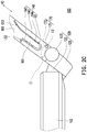
- FIG. 2C is a schematic diagram of a rotating stroke of the electronic device with multi screens in FIG. 1A .
- FIG. 2D is a schematic diagram of a rotating stroke of the electronic device with multi screens in FIG. 2A .
- FIG. 2E is a schematic connection diagram of a second connecting base and a second screen according to another embodiment of the invention.
- FIG. 3A is a schematic action diagram of a locking structure of the electronic device with multi screens in FIG. 2A locking a first screen and a second screen.
- FIG. 3B is a schematic action diagram of the locking structure of the electronic device with multi screens in FIG. 3A being unlocked on the first screen and the second screen.
- FIG. 3C is a schematic action diagram of the locking structure of the electronic device with multi screens in FIG. 2A locking a hinge module and a second connecting base.
- FIG. 3D is a schematic action diagram of the locking structure of the electronic device with multi screens in FIG. 3C being unlocked on the hinge module and the second connecting base.
- FIG. 3E is a schematic planar diagram of the electronic device with multi screens in FIG. 1A adopting a plurality of positioning magnets.
- FIG. 4A is a schematic top view of the electronic device with multi screens in FIG. 1A discounting the second screen.
- FIG. 4B is a schematic top view of a first screen of the electronic device with multi screens in FIG. 1A being clamped between a first connecting base and a second connecting base.
- FIG. 4C is a partial schematic enlarged three-dimensional view of the electronic device with multi screens in FIG. 4B .
- FIG. 1A is a schematic top view of a combination mode of an electronic device with multi screens according to an embodiment of the invention.
- FIG. 1B is a schematic exploded diagram of components of the electronic device with multi screens in FIG. 1A .
- FIG. 1C is a schematic enlarged diagram of some components of the electronic device with multi screens in FIG. 1B .
- the electronic device with multi screens 100 of the invention includes a host 110 , a hinge module 120 , a first connecting base 130 , a second connecting base 140 , a first screen 150 , and a second screen 160 .
- the host 110 is configured to carry components such as a storage unit, a logical unit, a power supply unit, a transport unit, and an input unit.
- the hinge module 120 is pivotally connected to the host 110 and rotates along a first axial direction X 1 .
- the first connecting base 130 is fixed on one side 51 of the hinge module 120 , namely, the first connecting base 130 and the hinge module 120 are of an integrally formed structure.
- the second connecting base 140 is pivotally connected to a second side S 2 of the hinge module 120 and rotates along a second axial direction X 2 parallel to the first axial direction X 1 .
- the second connecting base 140 is adjacent to the first connecting base 130 .
- first connecting base 130 and the second connecting base 140 may respectively rotate along the first axial direction X 1 and the second axial direction X 2 , to achieve the effect of separating from each other.
- the first screen 150 is slidably disposed in the first connecting base 130 and the second connecting base 140 .
- the first screen 150 is suitable for sliding along a horizontal direction PD relative to the first connecting base 130 , so that the first screen 150 may partially protrude beyond the first connecting base 130 or be aligned to be folded on the first connecting base 130 and the second connecting base 140 .
- the first screen 150 is clamped at the first connecting base 130 by using a clamping structure (not shown in the figure). Therefore, the first screen 150 cannot be taken down from the first connecting base 130 .
- the second screen 160 is detachably disposed in the second connecting base 140 . Further, the second screen 160 is slidably disposed in the second connecting base 140 to be adjacent to the first screen 150 , and the first screen 150 and the second screen 160 are suitable for switching to a synchronous display mode or an individual display mode. When switching to the synchronous display mode, the first screen 150 and the second screen 160 display a same picture in combination, to expand the display range accordingly. When switching to the individual display mode, the first screen 150 and the second screen 160 respectively output different pictures, to achieve the effect of separated display accordingly.
- FIG. 2A is a schematic three-dimensional view of a separation mode of the electronic device with multi screens in FIG. 1A .
- FIG. 2B is a schematic side view of the electronic device with multi screens in FIG. 2A .
- FIG. 2C is a schematic diagram of a rotating stroke of the electronic device with multi screens in FIG. 1A .
- FIG. 2D is a schematic diagram of a rotating stroke of the electronic device with multi screens in FIG. 2A .
- FIG. 2E is a schematic connection diagram of a second connecting base and a second screen according to another embodiment of the invention.
- the second connecting base 140 is suitable for rotating relative to the hinge module 120 along the second axial direction X 2 to be aligned with or separated from the first connecting base 130 .
- the first screen 150 and the second screen 160 are flush with each other and switch to the synchronous display mode.
- the first screen 150 and the second screen 160 include an included angle A therebetween and switch to the individual display mode.
- the first screen 150 and the second screen 160 may be respectively displayed in different directions, which is suitable for users in different directions to watch, and the second screen 160 may further provide use manners such as touch control and writing.
- the hinge module 120 includes a support portion 121 , a first rotating shaft portion 122 , and a pivot portion 123 .
- the first rotating shaft portion 122 is disposed on one side of the support portion 121 facing the host 110 and located in a rotating groove RG of the host 110 , and the first rotating shaft portion 122 is rotatably connected to two rotating portions 111 of the host 110 .
- the pivot portion 123 is disposed on the other side S 2 of the support portion 121 and spaced from the first connecting base 130 .
- the second connecting base 140 includes a second rotating shaft portion 141 and a lower curved surface CS.
- the second rotating shaft portion 141 is pivotally connected to the pivot portion 123 of the hinge module 120 and the lower curved surface CS partially accommodates the pivot portion 123 .
- the lower curved surface CS is suitable for sliding on the pivot portion 123 .
- the first connecting base 130 includes a first guide wall 131 , a first limiting wall 132 , a first groove G 1 , and a plurality of first protrusions 133 .
- the first groove G 1 is formed between the first guide wall 131 and the first limiting wall 132 .
- the first screen 150 includes a first clamping portion 151 , a first guide surface GS 1 , and a first limiting surface LS 1 .
- the first clamping portion 151 is clamped in the first groove G 1 , and the first guide surface GS 1 and the first limiting surface LS 1 respectively abut against the first guide wall 131 and the first limiting wall 132 .
- a plurality of first protrusions 133 are respectively formed on the first guide wall 131 and the first limiting wall 132 and located in the first groove G 1 , and each first protrusion 133 interferes with and limits the first clamping portion 151 of the first screen 150 , to avoid shaking of the first screen 150 in the first connecting base 130 .
- an extended length L of the first guide wall 131 relative to the hinge module 120 is greater than an extended length L of the first limiting wall 132 relative to the hinge module 120 .
- the first limiting wall 132 is formed on one side of the first connecting base 130 close to the host 110 and the first guide wall 131 is formed on one side of the first connecting base 130 away from the host 110 .
- the first limiting wall is, for example, formed on one side of the first connecting base away from the host and the first guide wall is formed on one side (not shown in the figure) of the first connecting base close to the host.
- the second connecting base 140 includes a second guide wall 142 , a second limiting wall 143 , a second groove G 2 , and a plurality of second protrusions 144 .
- the second groove G 2 is formed between the second guide wall 142 and the second limiting wall 143 .
- the second screen 160 includes a second clamping portion 161 , a second guide surface GS 2 , and a second limiting surface LS 2 .
- the second clamping portion 161 is clamped in the second groove G 2 , and the second guide surface GS 2 and the second limiting surface LS 2 respectively abut against the second guide wall 142 and the second limiting wall 143 .
- a plurality of the second protrusions 143 are respectively formed on the second guide wall 142 and the second limiting wall 143 and located in the second groove G 2 , and each second protrusion 143 interferes with and limits the second clamping portion 161 of the second screen 160 , to prevent the second screen 160 from being separated from the second connecting base 140 in a vertical direction VD.
- an extended length L of the second guide wall 142 relative to the hinge module 120 is greater than an extended length L of the second limiting wall 143 relative to the hinge module 120 .
- the second limiting wall 143 is formed on one side of the second connecting base 140 close to the host 110 and the second guide wall 142 is formed on one side of the second connecting base 140 away from the host 110 , and a mounting direction of the second screen 160 is from the host 110 to the outside.
- the second limiting wall 143 a is formed on one side of the second connecting base 140 a away from the host 110 a and the second guide wall 142 a is formed on one side of the second connecting base 140 a close to the host 110 a , and a mounting direction of the second screen 160 is from the outside to the host 110 a.
- the electronic device with multi screens 100 includes a stroke guide structure 170 , including a limiting column 171 and a fan-shaped guide groove 172 , respectively disposed on a surface corresponding to the first connecting base 130 and the second connecting base 140 .
- the limiting column 171 is formed on the first connecting base 130 and the fan-shaped guide groove 172 is formed on the second connecting base 140 .
- the limiting column 171 slidably penetrates the fan-shaped guide groove 172 .
- the limiting column 171 abuts against a second end E 2 of the fan-shaped guide groove 172 close to the host 110 .
- the limiting column 171 is separated from the second end E 2 of the fan-shaped guide groove 172 and slides toward a first end E 1 of the fan-shaped guide groove 172 , until the limiting column 171 abuts against the first end E 1 (which is a maximum rotating angle of the second connecting base 140 relative to the first connecting base 130 ). Further, through the abutting of the fan-shaped guide groove 172 and the limiting column 171 , the rotating angle of the second connecting base 140 relative to the first connecting base 130 is limited.
- FIG. 3A is a schematic action diagram of a locking structure of the electronic device with multi screens in FIG. 2A locking a first screen and a second screen.
- FIG. 3B is a schematic action diagram of the locking structure of the electronic device with multi screens in FIG. 3A being unlocked on the first screen and the second screen.
- the electronic device with multi screens 100 includes a locking structure 180 , slidably disposed in the second screen 160 .
- the locking structure 180 is suitable for sliding toward the first screen 150 automatically or manually to lock the first screen 150 and the second screen 160 .
- the first screen 150 and the second screen 160 are connected integrally, and no matter which screen (the first screen 150 or the second screen 160 ) a force is applied to, both the first screen 150 and the second screen 160 rotate synchronously relative to the host 110 .
- the locking structure 180 includes a locking block 181 , a toggle block 182 , a first magnet 183 , a second magnet 184 , and a third magnet 185 .
- the locking block 181 is slidably disposed in the second screen 160 and is suitable for penetrating the first screen 150 .
- the toggle block 182 is vertically disposed on one end of the locking block 181 away from the first screen 150 and extends upward beyond the second screen 160 , and the toggle block 182 is configured to be manually adjusted by a user.
- the first magnet 183 , the second magnet 184 , and third magnet 185 are respectively disposed on the first screen 150 , the second screen 160 , and the locking block 181 .
- the locking block 181 when the first magnet 183 and the third magnet 185 are attracted to each other, the locking block 181 is driven to penetrate the first screen 150 , so that the first screen 150 and the second screen 160 lock each other.
- the locking block 181 when the second magnet 184 and the third magnet 185 are attracted to each other, the locking block 181 is driven away from the first screen 150 , so that the first screen 150 and the second screen 160 do not lock each other.
- the locking structure is, for example, disposed in the hinge module and suitable for locking the second connecting base, so that the second connecting base cannot rotate relative to the first connecting base, to achieve the objective of locking the first screen and the second screen.
- FIG. 3C is a schematic action diagram of the locking structure of the electronic device with multi screens in FIG. 2A locking a hinge module and a second connecting base.
- FIG. 3D is a schematic action diagram of the locking structure of the electronic device with multi screens in FIG. 3C being unlocked on the hinge module and the second connecting base.
- the electronic device with multi screens 100 includes a locking structure 180 a , slidably disposed in the support portion 121 of the hinge module 120 .
- the locking structure 180 a is suitable for sliding toward the second connecting base 140 automatically or manually to lock the support portion 121 and the second connecting base 140 .
- the first connecting base 130 and the second connecting base 140 are connected integrally, and no matter which screen (the first screen 150 or the second screen 160 ) a force is applied to, both the first screen 150 and the second screen 160 synchronously drive the first connecting base 130 and the second connecting base 140 to rotate relative to the host 110 .
- the locking structure 180 a includes a locking block 181 a , a toggle block 182 a , a first magnet 183 a , a second magnet 184 a , and a third magnet 185 a .
- the locking block 181 a is slidably disposed in the support portion 121 and is suitable for penetrating the second connecting base 140 a .
- the toggle block 182 a is vertically disposed on one end of the locking block 181 a away from the second connecting base 140 and extends beyond the support portion 121 , and the toggle block 182 a is configured to be manually adjusted by a user.
- the first magnet 183 a , the second magnet 184 a , and third magnet 185 a are respectively disposed on the support portion 121 , the second connecting base 140 , and the locking block 181 a.
- the locking block 181 a is driven to penetrate the second connecting base 140 , so that the support portion 121 and the second connecting base 140 lock each other.
- the locking block 181 a is driven away from the second connecting base 140 , so that the support portion 121 and the second connecting base 140 do not lock each other.
- FIG. 3E is a schematic planar diagram of the electronic device with multi screens in FIG. 1A adopting a plurality of positioning magnets.
- the second connecting base 140 is suitable for rotating relative to the hinge module 120 to be aligned with the first connecting base 130 , so that the first screen 150 and the second screen 160 are flush with each other, and a first display surface DS 1 of the first screen 150 and a second display surface DS 2 of the second screen 160 are located on a same plane.
- the electronic device with multi screens 100 further includes a plurality of positioning magnets 190 , respectively disposed on two opposite sides of the first screen 150 and the second screen 160 , and the plurality of corresponding positioning magnets 190 are attracted to each other magnetically, so that the first screen 150 and the second screen 160 may be connected stably, to prevent the first display surface DS 1 and the second display surface DS 2 from generating a height difference due to external factors.
- FIG. 1D is a schematic top view of a combination mode of an electronic device with multi screens according to another embodiment of the invention.
- a difference of the electronic device with multi screens 100 B in the present embodiment from the electronic device with multi screens 100 in FIG. 1A lies in:
- the electronic device with multi screens 100 B includes an integrally formed connecting base 130 b , fixed on a hinge module 120 b .
- a first screen 150 b is slidably disposed in the connecting base 130 b and includes a first display surface DS 1 .
- a second screen 160 b is detachably disposed in the connecting base 130 b and includes a second display surface DS 2 .
- the first screen 150 b and the second screen 160 b are flush with each other, and the first display surface DS 1 and the second display surface DS 2 are located on a same plane.
- FIG. 4A is a schematic top view of the electronic device with multi screens in FIG. 1A discounting the second screen.
- FIG. 4B is a schematic top view of a first screen of the electronic device with multi screens in FIG. 1A being clamped between a first connecting base and a second connecting base.
- FIG. 4C is a partial schematic enlarged three-dimensional view of the electronic device with multi screens in FIG. 4B .
- the following describes the process of the electronic device with multi screens 100 in the present embodiment switching to a single screen.
- the first clamping portion 151 of the first screen 150 is suitable for sliding relative to the first connecting base 130 to be clamped in the first groove G 1 of the first connecting base 130 and the second groove G 2 of the second connecting base 140 , so that two sides of the first screen 150 are aligned with two sides of the host 110 .
- the electronic device with multi screens 100 is the same as a general single-screen notebook computer, and is easy to carry.
- an expansion member (not shown in the figure) is suitable for being connected to the second clamping portion 161 (the second clamping portion 161 is provided with a wireless transmission module, a power supply port, or an audio signal port) of the second screen 160 . Therefore, the expansion member includes a battery, a loudspeaker, or a support frame. Accordingly, the second screen 160 is converted into a tablet computer used independently.
- the electronic device with multi screens of the invention includes the first screen and the second screen that may be aligned with each other and separated from each other, so that when being aligned with each other, the first screen and the second screen may be displayed in combination to increase the display range of a single visual angle, and when being separated from each other, the first screen and the second screen may be respectively displayed in different visual angles to be applicable to situations of discussions of a plurality of persons.
- the first connecting base and the second connecting base are disposed on two sides of the hinge module, so that the first screen and the second screen are located at the center of the host. In this way, disadvantages of causing a center-of-gravity shift and deviating a visual angle from the center can be avoided. Therefore, the electronic device with multi screens of the invention more conforms to ergonomics.
Landscapes
- Engineering & Computer Science (AREA)
- Theoretical Computer Science (AREA)
- Computer Hardware Design (AREA)
- Physics & Mathematics (AREA)
- Human Computer Interaction (AREA)
- General Engineering & Computer Science (AREA)
- General Physics & Mathematics (AREA)
- Mathematical Physics (AREA)
- Devices For Indicating Variable Information By Combining Individual Elements (AREA)
- Telephone Set Structure (AREA)
Abstract
Description
Claims (22)
Priority Applications (1)
| Application Number | Priority Date | Filing Date | Title |
|---|---|---|---|
| US16/801,148 US11221652B2 (en) | 2019-02-26 | 2020-02-26 | Electronic device with multi screens |
Applications Claiming Priority (3)
| Application Number | Priority Date | Filing Date | Title |
|---|---|---|---|
| US201962810915P | 2019-02-26 | 2019-02-26 | |
| US201962836742P | 2019-04-22 | 2019-04-22 | |
| US16/801,148 US11221652B2 (en) | 2019-02-26 | 2020-02-26 | Electronic device with multi screens |
Publications (2)
| Publication Number | Publication Date |
|---|---|
| US20200272201A1 US20200272201A1 (en) | 2020-08-27 |
| US11221652B2 true US11221652B2 (en) | 2022-01-11 |
Family
ID=72141867
Family Applications (1)
| Application Number | Title | Priority Date | Filing Date |
|---|---|---|---|
| US16/801,148 Active US11221652B2 (en) | 2019-02-26 | 2020-02-26 | Electronic device with multi screens |
Country Status (3)
| Country | Link |
|---|---|
| US (1) | US11221652B2 (en) |
| CN (1) | CN111610819B (en) |
| TW (1) | TWI727677B (en) |
Cited By (4)
| Publication number | Priority date | Publication date | Assignee | Title |
|---|---|---|---|---|
| USD962223S1 (en) * | 2019-10-31 | 2022-08-30 | Quanta Computer Inc. | Laptop computer |
| US20220326741A1 (en) * | 2021-04-07 | 2022-10-13 | Hewlett-Packard Development Company, L.P. | Electronic device display panels |
| US20230094599A1 (en) * | 2021-09-28 | 2023-03-30 | Lenovo (Beijing) Limited | Rotation shaft assembly and electronic device |
| US20230221758A1 (en) * | 2022-01-13 | 2023-07-13 | Steven Daluz | Portable monitor workstation |
Families Citing this family (10)
| Publication number | Priority date | Publication date | Assignee | Title |
|---|---|---|---|---|
| CN113039770B (en) * | 2018-12-29 | 2023-03-31 | Oppo广东移动通信有限公司 | Mobile terminal |
| CN113741621B (en) * | 2020-05-27 | 2024-12-03 | 华硕电脑股份有限公司 | Electronic Devices |
| USD1049095S1 (en) * | 2020-07-03 | 2024-10-29 | Compal Electronics, Inc. | Foldable electronic device with dual display screens |
| TWI803886B (en) * | 2020-09-15 | 2023-06-01 | 仁寶電腦工業股份有限公司 | Foldable electronic device |
| CN114607875B (en) * | 2020-12-03 | 2024-12-10 | 宸展光电(厦门)股份有限公司 | Limiting shaft and dual-screen device using the same |
| CN113246868B (en) * | 2021-05-12 | 2024-10-15 | 天派电子(深圳)有限公司 | Rotatory many screens vehicle-mounted electronic equipment system |
| CN114564075B (en) * | 2021-06-21 | 2024-11-29 | 深圳市艾宝科技有限公司 | Double-screen notebook computer and assembling method thereof |
| CN116339658A (en) * | 2021-12-23 | 2023-06-27 | 联想(北京)有限公司 | Electronic equipment |
| CN114251351B (en) * | 2022-01-12 | 2024-10-11 | 上海海事大学 | Bionic expandable structure and driving mechanism |
| TWI903928B (en) * | 2024-01-24 | 2025-11-01 | 仁寶電腦工業股份有限公司 | Method for operating electronic apparatus based on gaze tracking and electronic apparatus |
Citations (9)
| Publication number | Priority date | Publication date | Assignee | Title |
|---|---|---|---|---|
| US20080062625A1 (en) * | 1999-10-18 | 2008-03-13 | Jeffrey Batio | Portable computer for dual, rotatable screens |
| US20090102744A1 (en) | 2004-10-19 | 2009-04-23 | Pranil Ram | Multiple monitor display apparatus |
| CN101533295A (en) | 2008-03-11 | 2009-09-16 | 联想(北京)有限公司 | Double-screen notebook computer |
| US7864514B2 (en) * | 2007-10-09 | 2011-01-04 | Samsung Electronics Co., Ltd. | Display device |
| US20120162080A1 (en) | 2010-12-24 | 2012-06-28 | Hon Hai Precision Industry Co., Ltd. | Dual-screen notebook computer with keyboard |
| US9167711B2 (en) * | 2012-01-03 | 2015-10-20 | Samsung Electronics Co., Ltd. | Mobile apparatus |
| US20180129252A1 (en) * | 2002-06-27 | 2018-05-10 | Intel Corporation | Multiple mode display apparatus |
| US20190004568A1 (en) | 2017-06-30 | 2019-01-03 | Dell Products L.P. | Information handling system with multiple detachable displays |
| TWI653524B (en) | 2017-12-26 | 2019-03-11 | 宏碁股份有限公司 | Electronic device with multiple screen modules |
Family Cites Families (7)
| Publication number | Priority date | Publication date | Assignee | Title |
|---|---|---|---|---|
| KR100378996B1 (en) * | 2000-02-26 | 2003-04-08 | 전정희 | portable computer mounted separable monitor or multifuntional augmented separable multi-monitor |
| TWI270618B (en) * | 2005-10-18 | 2007-01-11 | Asustek Comp Inc | Rotating shaft structure and foldable electronic device using the same |
| TWI470404B (en) * | 2011-04-07 | 2015-01-21 | Wistron Corp | Adjusting device of adjusting view angle of a panel module and computer system having the same |
| TW201332419A (en) * | 2012-01-18 | 2013-08-01 | Hannspree Inc | Electronic device having an adjustable angle support by engagement between resilient protrusions and recesses |
| US9568952B2 (en) * | 2014-09-09 | 2017-02-14 | Portal Dual Inc. | Display device apparatus |
| CN204314774U (en) * | 2014-11-19 | 2015-05-06 | 苏州嘉辰悦电子科技有限公司 | Double screen flat computer |
| CN109144171B (en) * | 2017-06-27 | 2022-03-18 | 比亚迪股份有限公司 | Take-up device of three-screen notebook and three-screen notebook |
-
2020
- 2020-02-26 US US16/801,148 patent/US11221652B2/en active Active
- 2020-02-26 CN CN202010121350.9A patent/CN111610819B/en active Active
- 2020-02-26 TW TW109106160A patent/TWI727677B/en active
Patent Citations (10)
| Publication number | Priority date | Publication date | Assignee | Title |
|---|---|---|---|---|
| US20080062625A1 (en) * | 1999-10-18 | 2008-03-13 | Jeffrey Batio | Portable computer for dual, rotatable screens |
| US20180129252A1 (en) * | 2002-06-27 | 2018-05-10 | Intel Corporation | Multiple mode display apparatus |
| US20090102744A1 (en) | 2004-10-19 | 2009-04-23 | Pranil Ram | Multiple monitor display apparatus |
| US20150212546A1 (en) * | 2004-10-19 | 2015-07-30 | Pranil Ram | Multiple Monitor Display Apparatus |
| US7864514B2 (en) * | 2007-10-09 | 2011-01-04 | Samsung Electronics Co., Ltd. | Display device |
| CN101533295A (en) | 2008-03-11 | 2009-09-16 | 联想(北京)有限公司 | Double-screen notebook computer |
| US20120162080A1 (en) | 2010-12-24 | 2012-06-28 | Hon Hai Precision Industry Co., Ltd. | Dual-screen notebook computer with keyboard |
| US9167711B2 (en) * | 2012-01-03 | 2015-10-20 | Samsung Electronics Co., Ltd. | Mobile apparatus |
| US20190004568A1 (en) | 2017-06-30 | 2019-01-03 | Dell Products L.P. | Information handling system with multiple detachable displays |
| TWI653524B (en) | 2017-12-26 | 2019-03-11 | 宏碁股份有限公司 | Electronic device with multiple screen modules |
Non-Patent Citations (2)
| Title |
|---|
| "Office Action of Taiwan Counterpart Application", dated Aug. 6, 2020, pp. 1-5. |
| Office Action of China Counterpart Application, dated Jun. 25, 2021, pp. 1-6. |
Cited By (5)
| Publication number | Priority date | Publication date | Assignee | Title |
|---|---|---|---|---|
| USD962223S1 (en) * | 2019-10-31 | 2022-08-30 | Quanta Computer Inc. | Laptop computer |
| US20220326741A1 (en) * | 2021-04-07 | 2022-10-13 | Hewlett-Packard Development Company, L.P. | Electronic device display panels |
| US20230094599A1 (en) * | 2021-09-28 | 2023-03-30 | Lenovo (Beijing) Limited | Rotation shaft assembly and electronic device |
| US11762432B2 (en) * | 2021-09-28 | 2023-09-19 | Lenovo (Beijing) Limited | Rotation shaft assembly and electronic device |
| US20230221758A1 (en) * | 2022-01-13 | 2023-07-13 | Steven Daluz | Portable monitor workstation |
Also Published As
| Publication number | Publication date |
|---|---|
| TWI727677B (en) | 2021-05-11 |
| CN111610819B (en) | 2022-01-25 |
| US20200272201A1 (en) | 2020-08-27 |
| TW202032319A (en) | 2020-09-01 |
| CN111610819A (en) | 2020-09-01 |
Similar Documents
| Publication | Publication Date | Title |
|---|---|---|
| US11221652B2 (en) | Electronic device with multi screens | |
| US9141137B2 (en) | Electronic device with keyboard | |
| CN107153444B (en) | A kind of intelligent terminal and its method for displaying projection | |
| US6891722B2 (en) | Magnetic locking device | |
| US8982543B2 (en) | Slider for keyboard | |
| US20090091881A1 (en) | Display device | |
| US20170038799A1 (en) | Reconfigurable touch screen computing device | |
| US9778680B2 (en) | Electronic device | |
| US10470564B2 (en) | Support device | |
| US10063268B2 (en) | Portable electronic device support | |
| US10203729B1 (en) | Portable electronic device | |
| US10487977B2 (en) | Supporting assembly and electronic device using the same | |
| CN109171193B (en) | Conference desk | |
| CN103259888A (en) | Mobile terminal | |
| US10574799B2 (en) | Mobile terminal with camera arranged on movable shell | |
| US7057888B2 (en) | Retractable and extendable camera and microphone array computer system | |
| US20140192471A1 (en) | Portable Electronic Device | |
| US11644863B2 (en) | Electronic device | |
| CN110432655A (en) | Multifunction display increases accepting rack | |
| US20050270730A1 (en) | Extendable multi-screen flat panel (computer / television) monitor enabling increased workspace and viewable monitor surface | |
| JP2002072898A (en) | Display device and information processing device | |
| US20210034103A1 (en) | Data processing method, device, and electronic apparatus | |
| KR20100097882A (en) | Notebook computer | |
| US8189826B2 (en) | Display device | |
| CN106886248B (en) | portable electronic device |
Legal Events
| Date | Code | Title | Description |
|---|---|---|---|
| AS | Assignment |
Owner name: COMPAL ELECTRONICS, INC., TAIWAN Free format text: ASSIGNMENT OF ASSIGNORS INTEREST;ASSIGNORS:TZOU, JYH-CHYANG;LIU, HAN-TSAI;CHEN, PAI-FENG;AND OTHERS;REEL/FRAME:051927/0422 Effective date: 20200226 |
|
| FEPP | Fee payment procedure |
Free format text: ENTITY STATUS SET TO UNDISCOUNTED (ORIGINAL EVENT CODE: BIG.); ENTITY STATUS OF PATENT OWNER: LARGE ENTITY |
|
| STPP | Information on status: patent application and granting procedure in general |
Free format text: DOCKETED NEW CASE - READY FOR EXAMINATION |
|
| STPP | Information on status: patent application and granting procedure in general |
Free format text: NON FINAL ACTION MAILED |
|
| STPP | Information on status: patent application and granting procedure in general |
Free format text: RESPONSE TO NON-FINAL OFFICE ACTION ENTERED AND FORWARDED TO EXAMINER |
|
| STPP | Information on status: patent application and granting procedure in general |
Free format text: FINAL REJECTION MAILED |
|
| STPP | Information on status: patent application and granting procedure in general |
Free format text: RESPONSE AFTER FINAL ACTION FORWARDED TO EXAMINER |
|
| STPP | Information on status: patent application and granting procedure in general |
Free format text: NOTICE OF ALLOWANCE MAILED -- APPLICATION RECEIVED IN OFFICE OF PUBLICATIONS |
|
| STPP | Information on status: patent application and granting procedure in general |
Free format text: PUBLICATIONS -- ISSUE FEE PAYMENT RECEIVED |
|
| STPP | Information on status: patent application and granting procedure in general |
Free format text: PUBLICATIONS -- ISSUE FEE PAYMENT VERIFIED |
|
| STCF | Information on status: patent grant |
Free format text: PATENTED CASE |
|
| MAFP | Maintenance fee payment |
Free format text: PAYMENT OF MAINTENANCE FEE, 4TH YEAR, LARGE ENTITY (ORIGINAL EVENT CODE: M1551); ENTITY STATUS OF PATENT OWNER: LARGE ENTITY Year of fee payment: 4 |