US11221318B2 - Adsorption/desorption-based sensor for volatile organic compounds (VOCs) - Google Patents
Adsorption/desorption-based sensor for volatile organic compounds (VOCs) Download PDFInfo
- Publication number
- US11221318B2 US11221318B2 US16/521,018 US201916521018A US11221318B2 US 11221318 B2 US11221318 B2 US 11221318B2 US 201916521018 A US201916521018 A US 201916521018A US 11221318 B2 US11221318 B2 US 11221318B2
- Authority
- US
- United States
- Prior art keywords
- chamber
- gas
- detector
- line
- voc
- Prior art date
- Legal status (The legal status is an assumption and is not a legal conclusion. Google has not performed a legal analysis and makes no representation as to the accuracy of the status listed.)
- Expired - Fee Related, expires
Links
- DRILURWOEDSAJP-UHFFFAOYSA-N CC(C)=O.CC(C)O.CCCCO.CCO.CCOCC.CO Chemical compound CC(C)=O.CC(C)O.CCCCO.CCO.CCOCC.CO DRILURWOEDSAJP-UHFFFAOYSA-N 0.000 description 1
Images


Classifications
-
- G—PHYSICS
- G01—MEASURING; TESTING
- G01N—INVESTIGATING OR ANALYSING MATERIALS BY DETERMINING THEIR CHEMICAL OR PHYSICAL PROPERTIES
- G01N33/00—Investigating or analysing materials by specific methods not covered by groups G01N1/00 - G01N31/00
- G01N33/0004—Gaseous mixtures, e.g. polluted air
- G01N33/0009—General constructional details of gas analysers, e.g. portable test equipment
- G01N33/0026—General constructional details of gas analysers, e.g. portable test equipment using an alternating circulation of another gas
-
- G—PHYSICS
- G01—MEASURING; TESTING
- G01N—INVESTIGATING OR ANALYSING MATERIALS BY DETERMINING THEIR CHEMICAL OR PHYSICAL PROPERTIES
- G01N33/00—Investigating or analysing materials by specific methods not covered by groups G01N1/00 - G01N31/00
- G01N33/0004—Gaseous mixtures, e.g. polluted air
- G01N33/0009—General constructional details of gas analysers, e.g. portable test equipment
- G01N33/0011—Sample conditioning
- G01N33/0014—Sample conditioning by eliminating a gas
-
- G—PHYSICS
- G01—MEASURING; TESTING
- G01N—INVESTIGATING OR ANALYSING MATERIALS BY DETERMINING THEIR CHEMICAL OR PHYSICAL PROPERTIES
- G01N33/00—Investigating or analysing materials by specific methods not covered by groups G01N1/00 - G01N31/00
- G01N33/0004—Gaseous mixtures, e.g. polluted air
- G01N33/0006—Calibrating gas analysers
Definitions
- This invention relates generally to gas sensors and more specifically to an adsorption/desorption-based gas sensor system that can discriminate and identify a wide range of volatile organic compounds (VOCs).
- VOCs volatile organic compounds
- VOC sensors must have high selectivity, i.e., the ability to discriminate between two VOCs that are chemically and structurally very similar; and high sensitivity, i.e., the ability to detect very low concentrations of a single VOC.
- Gas chromatography-mass spectrometry (GCMS) and infra-red spectrophotometry (also known as Fourier-transform infrared spectroscopy or FTIR) instruments are selective tools for VOC detection; however, these expensive, bulky, and maintenance-heavy instruments are limited to benchtop analytics.
- Electrochemical (EC) sensors are sensitive and selective for a handful of low molecular weight gases that are highly redox active (e.g., SO 2 , NO 2 , O 2 , CO, etc.), but suffer from a lack of selectivity with VOCs, which are organic compounds with 6-12 carbons (e.g., ethanol, toluene, benzene).
- Quartz crystal microbalance (QCM) sensors are a class of sensitive piezoelectric sensors that are capable of discriminating between two VOCs based upon the molecular weight (MW) of the VOCs; however, this type of discrimination is not effective where two VOCs have the same MW.
- MOS sensors which are portable and low-cost, are the most widely used gas sensors. While MOS sensors have high sensitivity for VOCs (ppb level for certain VOCs), MOS sensors lack sufficient selectivity.
- the present invention overcomes the need in the art by providing a sensitive and selective adsorption/desorption-based gas sensor system comprising at least one gas detector and at least one microporous material.
- a method of detecting at least one volatile organic compound comprising the steps of: providing a first chamber and a second chamber connected in series, wherein the first chamber contains a porous material that adsorbs an amount of the at least one VOC and the second chamber contains a detector for detecting a presence and concentration of the at least one VOC; introducing a gas without the at least one VOC into the second chamber while bypassing the first chamber; establishing a first baseline electronic signal corresponding to the gas without the at least one VOC, wherein the first baseline electronic signal is generated by the detector in the second chamber; introducing at least one VOC into the second chamber while bypassing the first chamber; detecting, over time, the presence of the at least one VOC in the second chamber by establishing a second electronic signal corresponding to the concentration of the at least one VOC in the second chamber, wherein the second electronic signal is generated by the detector in the second chamber; re-routing the gas so that it is directed into the first chamber, wherein an
- each of the steps are carried out in turn.
- a system comprising a first chamber comprising a crystalline microporous material for adsorbing and desorbing at least one gas; a second chamber comprising a gas detector for detecting and measuring a concentration of the least one gas; a pass-through line comprising an input, a first line, and a second line, wherein the first line bypasses the first chamber and passes through the second chamber and the second line passes through the first and second chambers, wherein upon entry of the at least one gas into the system, the at least one gas is routed to the second chamber via the input and the first line, wherein the gas detector in the second chamber generates a signal over time corresponding to the concentration of the at least one gas in the second chamber, and wherein the at least one gas is rerouted from the second chamber to the first chamber via the input and the second line, wherein an amount of the at least one gas is first adsorbed onto the crystalline microporous material and then some or all of the amount of the at least one gas is
- a system comprising: a first chamber comprising a crystalline microporous material for adsorbing and desorbing at least one gas; a second chamber comprising a gas detector for detecting and measuring a concentration of the least one gas; a pass-through line comprising, an input, an output, a first line that bypasses the first chamber and runs from the input to the output via the second chamber, and a second line that passes from the input through the first and second chambers to the output, wherein upon entry of the at least one gas into the system via the input, the at least one gas is (i) routed to the second chamber via the first line, wherein the at least one gas is detected, and (ii) rerouted to the first chamber via the second line, wherein an amount of the at least one gas is adsorbed onto the crystalline microporous material and then some or all of the amount of the at least one gas is desorbed from the microporous crystalline structure, wherein the gas detector in the second chamber
- the porous or crystalline microporous material is selected from the group consisting of a metal organic framework, a covalent organic framework, a metal-organic polyhedral, a coordination polymer, zeolites, microporous carbonaceous materials, and combinations thereof.
- the porous or crystalline microporous material comprises a metal organic framework.
- the first chamber further comprises a heating plate.
- the porous or crystalline microporous material in the first chamber is recycled by heating the first chamber to a temperature that does not alter the structure of the porous or microporous crystalline material.
- the detector in the second chamber is selected from the group consisting of a gas chromatography mass spectrometer, an infra-red spectrophotometer, an electrochemical sensor, a quartz crystal microbalance, a metal oxide semiconductor, and combinations thereof.
- the detector or gas detector in the second chamber comprises a metal oxide thin film.
- the metal oxide thin film in the second chamber is deposited on a membrane heater fitted with microelectrodes.
- the at least one gas is a volatile organic compound.
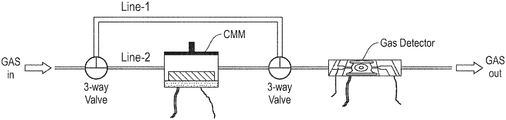
- FIG. 1 is a schematic diagram of an adsorption/desorption (AD) sensor as described herein.
- AD adsorption/desorption
- FIG. 2 is a graph showing the three separate parts of an adsorption/desorption profile produced from an AD sensor.
- FIGS. 3A-3C are graphs showing the adsorption/desorption profiles of 1-butanol ( FIG. 3A ), isopropanol ( FIG. 3B ) and ethanol ( FIG. 3C ) with the metal organic framework (MOF), Mg-MOF-74.
- MOF metal organic framework
- FIG. 4 is a graph showing the adsorption/desorption profiles of acetone and ethanol with the MOF, Al-MIL-53.
- FIG. 5 is a graph showing the adsorption/desorption profile of acetone with two different MOFS, Al-MIL-53 and HKUST-1.
- FIG. 6 is a graph showing the adsorption/desorption profiles for a 1:1 mixture and a 3:1 mixture of isopropanol:acetone with the MOF, Mg-MOF-74.
- FIG. 7 is a graph showing the recovery profile for the MOF, Mg-MOF-74.
- volatile organic compound means any organic chemical compound (either liquid or solid) that evaporates under normal indoor atmospheric conditions of temperature and pressure.
- VOCs include, without limitation, acetone, benzene, bromodichloromethane, bromomethane, butane, butanol, carbon disulfide, carbon tetrachloride, chloroform, chloromethane, dibromochloropropane, dibromomethane, dichlorobenzenes, dichloropropenes, diethyl ether, ethanol, ethyl benzene, ethylene dibromide, formaldehyde, gasoline, hexachlorobutadiene, hexachloroethane, hexane, hydrazines, isopropanol, n-propanol, methane, methanol, methyl chloride, methyl mercaptan, nitrobenzene, propane,
- gas and “gases” are meant to refer to all gaseous chemicals and chemical compounds, including gaseous VOCs and gaseous chemicals and/or chemical compounds that are not VOCs.
- the VOCs defined herein are understood to be included in the term “gas” and “gases.” Examples of gases that are not VOCs include, without limitation, air, oxygen, nitrogen, carbon monoxide, carbon dioxide, carbonic acid, metallic carbides, metallic carbonates, and ammonium carbonate.
- gas line and “gas lines” refers to a pipe or hose intended to transfer a gas (including VOCs) from one source (e.g., a main supply of the gas) to another source (e.g., a device and/or a portion of a device).
- a gas including VOCs
- one source e.g., a main supply of the gas
- another source e.g., a device and/or a portion of a device.
- the terms “sensor,” “gas sensor,” and “gas sensor system” are used interchangeably to refer to a system that differentiates between two or more gases.
- detector and “gas detector” refer to a device that is capable of identifying gases, but is not used to differentiate between two or more gases.
- MOF metal organic framework
- the pores of a MOF may range from 0.5 nm to 10 nm, depending on the metal ion/organic ligand combination used for the MOF. Owing to high surface area (>1000 m 2 /g), MOFs have high affinity and capacity for adsorption of gases including VOCs.
- the adsorption/desorption (AD) sensors described herein are sensors that exhibit high sensitivity (e.g., ppb-level sensitivity) and high selectivity in the detection and discrimination of low concentration VOCs that are similar in chemical properties, molecular weights, and/or size.
- VOCs include alcohols that vary by only one carbon center, such as:
- the AD sensor comprises a first chamber comprising a known amount of a crystalline microporous material (CMM) and a heating plate; a second chamber comprising a gas detector, a membrane heater, and interdigitated microelectrodes; a first gas line (also referred to herein as “line 1 ”) that directly reaches the gas detector chamber; and a second gas line (also referred to herein as “line 2 ”) that is parallel to the first gas line and that passes through the CMM chamber and arrives at the detector chamber.
- CMM crystalline microporous material
- the heating plate in the first chamber is a mm-sized heating plate.
- the gas detector in the second chamber is deposited on the membrane heater.
- a valve controls the gas flow through the first and second gas lines.
- the valve is a three-way valve.
- the AD sensor is portable and thus applicable to field applications. The small size of the CMM chamber and the gas detector allows the AD sensor to be fitted into a hand-held device.
- the CMM is any microporous material that exhibits permanent porosity owing to a crystal structure.
- CMMs that may be used in the first chamber of the AD sensor include, without limitation, MOFs, covalent organic frameworks (COFs), metal-organic polyhedrals (MOPs), coordination polymer (CP), zeolites, microporous carbonaceous materials, and combinations thereof.
- MOFs covalent organic frameworks
- MOPs metal-organic polyhedrals
- CP coordination polymer
- zeolites microporous carbonaceous materials, and combinations thereof.
- the amount of CMM placed into the CMM chamber will depend on the CMM used.
- a MOF is used as the CMM in an appropriate concentration for the chamber, which may range from 1 ⁇ g to 100 mg.
- the gas detector is any high sensitivity gas detector.
- gas detectors that may be used in the second chamber of the AD sensor include, without limitation, gas chromatography mass spectrometers (GCMSs), Fourier-transform infrared spectrometers (FTIRs), electrochemical (EC) sensors, quartz crystal microbalances (QCMs), metal oxide semiconductor (MOS) detectors, and combinations thereof.
- the MOS detector is a semiconducting metal oxide thin film (MOxTF).
- metal oxides that may be used for a MOS detector, including a MOxTF, include, without limitation, aluminum oxide (Al 2 O 3 ), ceric dioxide (CeO 2 ), cuprous oxide (Cu 2 O), cupric oxide (CuO), copper peroxide (CuO 2 ), copper(III) oxide (Cu 2 O 3 ), indium oxide (In 2 O 3 ), ferric oxide (Fe 2 O 3 ), iron(II) oxide FeO, iron(II,III) oxide (Fe 3 O 4 ), manganese dioxide (MnO 2 ), tin(IV) oxide (SnO 2 ), titanium dioxide (TiO 2 ), tungsten trioxide (WO 3 ), zinc oxide (ZnO), and combinations thereof.
- Al 2 O 3 aluminum oxide
- CeO 2 ceric dioxide
- CuO cuprous oxide
- CuO cupric oxide
- CuO copper peroxide
- Cu 2 O 3 copper(III) oxide
- indium oxide In 2 O 3
- ferric oxide Fe 2 O 3
- a gas without any VOC is passed through line 1 , bypassing line 2 .
- the electronic signal generated by the gas sensor establishes a baseline value for the system.
- the VOC-free gas may be dry air (i.e., a mixture of nitrogen and oxygen), or any other gas provided that the gas is VOC-free.
- Parts 1 and 2 show the electronic signal activity of the AD sensor when line 1 is open and line 2 is closed.
- Part 1 shows the value when a baseline gas (such as dry air) is introduced into the AD sensor.
- a baseline gas such as dry air
- the signal generated by the gas detector is parallel to the x-axis with no detectable slope.
- Part 2 shows the electronic signal activity when a gas of interest (such as a VOC) is introduced into the AD sensor.
- the electronic signal generated by the gas detector increases until the slope reaches an extremum (the Part 2 extremum or influx extremum) at which time the signal becomes parallel to the x-axis.
- the increasing slope shown at Part 2 corresponds to the presence of a VOC in a sample.
- Part 3 allow for the discrimination of different gases: (1) the initial slope of the signal (a); (2) the duration of time for the plot to reach the adsorption extremum ( ⁇ t); (3) the difference between the detector signal (value at the y-axis) at the onset of Part 3 and that of the adsorption extremum ( ⁇ i); and (4) the slope of the signal from the time it reaches the adsorption extremum until it matches with the influx extremum (b).
- a the initial slope of the signal
- ⁇ t the duration of time for the plot to reach the adsorption extremum
- ⁇ i the difference between the detector signal (value at the y-axis) at the onset of Part 3 and that of the adsorption extremum
- ⁇ i the difference between the detector signal (value at the y-axis) at the onset of Part 3 and that of the adsorption extremum
- b the slope of the signal from the time it reaches the adsorption extremum until it matches with the influx extremum
- the AD sensor As the gases pass through the CMM and arrive at the detector chamber unhindered, the AD sensor has the ability to detect different gases with the same CMM because the chemical and/or structural differences of the individual VOCs are recognized differently by the chemical and structural aspects of the pores of a CMM.
- the result is a unique adsorption/desorption profile for every gas that passes through an AD sensor equipped with the same CMM; thus, the adsorption/desorption profiles for VOCs such as ethanol, isopropanol, methanol, acetone, and any combination of the foregoing will all be different from each other.
- FIGS. 3A-3C show the Part 3 profiles for ethanol ( FIG. 3A ), isopropanol ( FIG. 3B ), and 1-butanol ( FIG. 3C )—alcohols that differ by one methylene (—CH 2 —) group—run through the AD sensor with the MOF, Mg-MOF-74 (made internally pursuant to procedures known in the art) as the CMM and a MOxTF as the gas detector (Example 1).
- the ⁇ i values for the three alcohols are 0.17 ⁇ A for 1-butanol, 0.67 ⁇ A for isopropanol, and 1 ⁇ A for ethanol.
- the difference in the ⁇ i values are due to the Mg-MOF-74 having differential adsorption for the three different alcohols.
- the signal in the MOxTF detector resulting from the differential adsorption of the three alcohols in the CMM chamber allows these three similar alcohols to be readily discerned from each other from within a single sample.
- FIG. 4 shows the results of the introduction of the VOCs acetone and ethanol run through the AD sensor equipped with the MOF, Al-MIL-53 (aluminum terephthalate, BASF, Ludwigshafen, Germany) as the CMM and a MOxTF as the gas detector (Example 2).
- the two VOCs have identical Part 1 values and similar, but distinct, Part 2 and Part 3 profiles.
- the Part 3 profiles show ⁇ t (time) and ⁇ i (current) values of 21 sec and 8 ⁇ A, respectively, for acetone; and ⁇ t and ⁇ i values of 30 sec and 15 ⁇ A, respectively, for ethanol.
- the results of FIG. 4 demonstrate the sensitivity and selectively of the AD sensor for similar gases analyzed with the same CMM.
- FIG. 5 shows the Part 3 profiles for the VOC, acetone, run through the AD sensor with two separate MOFs as the CMMs; specifically, Al-MIL-53 and HKUST-1 (copper benzene-1,3,5-triccarboxylate, BASF, Ludwigshafen, Germany) and a MOxTF as the gas detector (Example 3).
- the Part 3 desorption profiles show ⁇ t and ⁇ i values of 21 sec and 8 ⁇ A, respectively, for acetone/Al-MIL-53; and ⁇ t and ⁇ i values of 32 sec and 11 ⁇ A, respectively, for acetone/HUSKT-1.
- the results of FIG. 5 show that different CMMs can produce distinct Part 3 profiles for the same gas.
- AD sensors equipped with multiple MOFs can selectively discriminate a wide variety of gases (including VOCs) with very high sensitivity.
- FIG. 6 shows two different Part 3 profiles for isopropanol:acetone (1:1) and isopropanol:acetone (3:1) run through the AD sensor with Mg-MOF-74 as the CMM and a MOxTF as the gas detector (Example 4).
- the MOF may be recovered by heating the chamber to a temperature between 25-500° C. in a flow of analyte-free air (i.e., with no gases or VOCs). At temperatures above 500° C., the morphology of a thin-film MOF may change; thus, the temperature tolerance of a particular MOF should be known prior to attempting a MOF recovery.
- FIG. 7 shows the recovery profile of a MOF from the CMM chamber of an AD sensor (Example 5). In FIG.
- the VOC, ethanol was run through the first and second chambers of the AD sensor through line 2 (line 1 closed) with the MOF, Al-MIL-53, in the first chamber for several runs one after the other. After each run, the influx of the VOC was stopped and dry air was introduced into the CMM chamber with heating to 100° C. to accelerate removal of the VOC and bring the MOF back to its original state. After heating, the MOF was completely desorbed of the VOC and was ready to measure another VOC sample.
- the AD sensor described herein has application in a variety of industries, including, without limitation, the food industry to identify the onset of food spoilage and the wine industry to identify the time for bottling.
- the AD sensor also has utility in identifying harmful VOCs that may be contributing to pollution and/or unsafe workplace conditions.
- the portable nature of the AD sensor allows the sensor to be useful for field use outside of a laboratory setting.
- the AD sensor was set up according to the schematic shown in FIG. 1 with 7 mg of the MOF, Mg-MOF-74, in the CMM chamber and SnO 2 as the MOxTF in the detector chamber.
- a baseline value for the MOxTF was established by running dry air through line 1 at a rate of 50 sccm/min. The same rate of total influx was maintained for the introduction of the VOCs, 1-butanol, isopropanol, and ethanol, but with 45 sccm/min of dry air alone and 5 sccm/min of dry air saturated with the respective VOC.
- the graphs of the electrical output from the MOxTF for the 1-butanol, isopropanol, and ethanol runs are shown in FIGS. 3A-3C .
- 1-butanol ( FIG. 3A ) was introduced into the AD sensor by running a stream of dry air alone at 45 sccm/min plus dry air saturated with 1-butanol at 5 sccm/min with line 1 open and line 2 closed until the signal from the MOxTF increased from the baseline value (where the signal is parallel to the x-axis in FIG. 3A ) to the influx extremum (where the signal is also approximately parallel to the x-axis in FIG. 3A ). After reaching the influx extremum (which occurred at ⁇ 1105 sec and a current of ⁇ 6.49 ⁇ A), line 1 was closed and line 2 was opened to allow the 1-butanol to adsorb onto the MOF.
- the adsorption extremum occurred 10 seconds later (at ⁇ 1115 sec and a current of ⁇ 6.32 ⁇ A). The difference in current between the influx extremum and the adsorption extremum was ⁇ 0.17 ⁇ A. After the adsorption extremum was reached, the flow of the 1-butanol proceeded to pass through the CMM chamber and into the MOxTF detector resulting in a current increase. When the Part 3 profile reached close to the same level as the influx extremum ( ⁇ 65 sec later at ⁇ 1180 sec), the influx of 1-butanol was stopped and dry air was run through line 2 until the 1-butanol had desorbed from the MOF (the desorption is not shown in FIG. 3A ).
- the adsorption extremum occurred 35 seconds later (at ⁇ 810 secs and at a current of ⁇ 14.73 ⁇ A). The difference in current between the influx extremum and the adsorption extremum was ⁇ 0.67 ⁇ A. After the adsorption extremum was reached, the flow of the isopropanol proceeded to pass through the CMM chamber and into detector chamber resulting in a current increase. When the Part 3 profile became parallel to the x-axis, the influx of isopropanol was stopped and dry air was run through line 2 until the isopropanol had desorbed from the MOF. The adsorption behavior of isopropanol was found to be unique in that the Part 3 profile did not approach the same level as the influx extremum.
- the Mg-MOF-74 was recovered (Example 5), a new baseline was established (using dry air), and ethanol ( FIG. 3C ) was introduced into the AD sensor by running a stream of dry air alone at 45 sccm/min plus dry air saturated with ethanol at 5 sccm/min with line 1 open and line 2 closed until the influx extremum was reached (at ⁇ 630 sec and a current of ⁇ 16.2 ⁇ A). After reaching the influx extremum, line 1 was closed and line 2 was opened to allow the ethanol to adsorb onto the MOF. The adsorption extremum occurred 30 second later (at ⁇ 660 sec and a current of ⁇ 15.2 ⁇ A).
- the difference in current between the influx extremum and the adsorption extremum was ⁇ 1 ⁇ A.
- the flow of the ethanol proceeded to pass through the CMM chamber and into the detector chamber resulting in a current increase.
- the influx of ethanol was stopped and dry air was run through line 2 at 120 sccm/min until the ethanol had desorbed from the MOF (shown in FIG. 3C as the current drop between ⁇ 925-935 sec).
- the AD sensor was set up according to the schematic in FIG. 1 with 25 mg of the MOF, Al-MIL-53, in the CMM chamber and SnO 2 as the MOxTF in the detector chamber.
- a baseline value for the MOxTF was established by running dry air through line 1 at a rate of 50 sccm/min. The same rate of total influx was maintained for the introduction of the VOCs, acetone and ethanol, but with 45 sccm/min of dry air alone and 5 sccm/min of dry air saturated with the respective VOC.
- Acetone was introduced into the AD sensor by running a stream of dry air alone at 45 sccm/min plus dry air saturated with acetone at 5 sccm/min with line 1 open and line 2 closed until the influx extremum was reached (at ⁇ 589 sec and current of ⁇ 0.112 mA). After reaching the influx extremum, line 1 was closed and line 2 was opened to allow the acetone to adsorb onto the MOF. The adsorption extremum occurred 21 seconds later (at ⁇ 610 sec and a current of ⁇ 0.104 mA). The difference in current between the influx extremum and the adsorption extremum was ⁇ 8 ⁇ A.
- the Al-MIL-53 was recovered (Example 5), a new baseline was established (using dry air), and ethanol was introduced into the AD sensor by running a stream of dry air alone at 45 sccm/min plus dry air saturated with ethanol at 5 sccm/min with line 1 open and line 2 closed until the influx extremum was reached (at ⁇ 575 sec and a current of ⁇ 0.115 mA). After reaching the influx extremum, line 1 was closed and line 2 was opened to allow the ethanol to adsorb onto the MOF. The adsorption extremum occurred 30 seconds later (at ⁇ 605 secs and a current of ⁇ 0.100 mA).
- the difference in current between the influx extremum and the adsorption extremum was ⁇ 15 ⁇ A.
- the flow of the ethanol proceeded to pass through the CMM chamber and into the detector chamber resulting in a current increase.
- the influx of ethanol was stopped and dry air was run through line 2 until the acetone had desorbed from the MOF.
- the AD sensor was set up according to the schematic in FIG. 1 with 25 mg of the MOF, Al-MIL-53, in the CMM chamber and SnO 2 as the MOxTF in the detector chamber.
- a baseline value for the MOxTF was established by running dry air through line 1 at a rate of 50 sccm/min.
- acetone was introduced into the AD sensor by running a stream of dry air alone at 45 sccm/min plus dry air saturated with acetone at 5 sccm/min with line 1 open and line 2 closed until the influx extremum was reached (at ⁇ 689 sec and a current of ⁇ 0.1075 mA).
- the CMM chamber was cleared of the Al-MOF-53 and replaced with 25 mg of the MOF, HKUST-1.
- a baseline value for the MOxTF detector was again established by running dry air through line 1 at a rate of 50 sccm/min followed by the introduction of acetone into the AD sensor as described above.
- the influx extremum line 1 closed, line 2 open
- line 1 was closed and line 2 was opened to allow the acetone to adsorb onto the HKUST-1.
- the adsorption extremum occurred 32 seconds later (at ⁇ 732 sec and a current of ⁇ 0.0970 mA). The difference in current between the influx extremum and the adsorption extremum was ⁇ 11 ⁇ A. After the adsorption extremum was reached, the flow of the acetone proceeded to pass through the CMM chamber and into the detector chamber resulting in a current increase. Once the Part 3 profile reached close to the same level as the influx extremum ( ⁇ 198 seconds later at ⁇ 930 sec), the influx of acetone was stopped and dry air was run through line 2 until the acetone had desorbed from the HKUST-1.
- the AD sensor was set up according to the schematic in FIG. 1 with 7 mg of the MOF, Mg-MOF-74, in the CMM chamber and SnO 2 as the MOxTF in the detector chamber.
- a baseline value for the MOxTF was established by running dry air through line 1 at a rate of 50 sccm/min. The same rate of total influx was maintained for the introduction of the VOC mixtures, 1:1 isopropanol:acetone and 3:1 isopropanol:acetone, but with 45 sccm/min of dry air alone and 5 sccm/min of dry air saturated with the respective VOC mixtures.
- a 20 mL sample of 1:1 isopropanol:acetone (10 mL:10 mL; hereinafter “1:1 sample”) was introduced into the AD sensor by running a stream of dry air alone at 45 sccm/min plus dry air saturated with the 1:1 sample at 5 sccm/min with line 1 open and line 2 closed until the influx extremum was reached (at ⁇ 745 seconds and a current of ⁇ 61.1 ⁇ A). After reaching the influx extremum, line 1 was closed and line 2 was opened to allow the 1:1 sample to adsorb onto the MOF. The adsorption extremum occurred ⁇ 35 seconds later (at ⁇ 780 sec and a current of ⁇ 59.2 ⁇ A).
- the difference in current between the influx extremum and the adsorption extremum was ⁇ 1.9 ⁇ A.
- the flow of the 1:1 sample proceeded to pass through the CMM chamber and into the detector chamber resulting in a current increase.
- the influx of the 1:1 sample was stopped and dry air was run through line 2 until the 1:1 sample had desorbed from the MOF.
- the Mg-MOF-74 was recovered (Example 5), a new baseline was established (using dry air), and a 20 mL sample of 3:1 isopropanol:acetone (hereinafter “3:1 sample”) was introduced into the AD sensor by running a stream of dry air alone at 45 sccm/min plus dry air saturated with the 1:3 sample at 5 sccm/min with line 1 open and line 2 closed until the influx extremum was reached (at ⁇ 747 sec and a current of ⁇ 61.3 ⁇ A). After reaching the influx extremum, line 1 was closed and line 2 was opened to allow the acetone to adsorb onto the MOF.
- 3:1 sample 3:1 isopropanol:acetone
- the adsorption extremum occurred 38 seconds later (at ⁇ 785 sec and a current of ⁇ 58.3 ⁇ A). The difference in current between the influx extremum and the adsorption extremum was ⁇ 3 ⁇ A. After the adsorption extremum was reached, the flow of the 3:1 sample proceeded to pass through the CMM chamber and into the detector chamber resulting in a current increase. Once the Part 3 profile started becoming parallel to x-axis, the influx of the 1:3 sample was stopped and dry air was run through line 2 until the 3:1 sample had desorbed from the MOF.
- the AD sensor was set up according to the schematic in FIG. 1 with 25 mg of the MOF, Al-MIL-53, in the CMM chamber and SnO 2 as the MOxTF in the detector chamber.
- a baseline value for the MOxTF was established by running dry air through line 1 at a rate of 50 sccm/min.
- ethanol was introduced into the AD sensor by running a stream of dry air alone at a rate of 45 sccm/min plus dry air saturated with ethanol at a rate of 5 sccm/min with line 1 open and line 2 closed until the influx extremum was reached, at which time, line 1 was closed and line 2 was opened to allow the ethanol to adsorb onto the MOF.
- the flow of the ethanol proceeded to pass through the CMM chamber and into the detector chamber resulting in a current increase.
- the Al-MIL-53 was recovered by heating the Al-MIL-53 to 100° C. while passing a stream of dry air at 120 sccm/min. The Al-MIL-53 recovered to its original state ⁇ 1200 seconds ( ⁇ 20 minutes) later. Upon recovery of the Al-MIL-53, ethanol was run through the AD sensor in an identical run and the second recovery of the Al-MIL-53 also took ⁇ 20 minutes.
Landscapes
- Chemical & Material Sciences (AREA)
- Life Sciences & Earth Sciences (AREA)
- Engineering & Computer Science (AREA)
- Health & Medical Sciences (AREA)
- Medicinal Chemistry (AREA)
- Food Science & Technology (AREA)
- Combustion & Propulsion (AREA)
- Physics & Mathematics (AREA)
- Analytical Chemistry (AREA)
- Biochemistry (AREA)
- General Health & Medical Sciences (AREA)
- General Physics & Mathematics (AREA)
- Immunology (AREA)
- Pathology (AREA)
- Investigating Or Analyzing Materials By The Use Of Fluid Adsorption Or Reactions (AREA)
Abstract
Description

Claims (27)
Priority Applications (1)
| Application Number | Priority Date | Filing Date | Title |
|---|---|---|---|
| US16/521,018 US11221318B2 (en) | 2019-07-24 | 2019-07-24 | Adsorption/desorption-based sensor for volatile organic compounds (VOCs) |
Applications Claiming Priority (1)
| Application Number | Priority Date | Filing Date | Title |
|---|---|---|---|
| US16/521,018 US11221318B2 (en) | 2019-07-24 | 2019-07-24 | Adsorption/desorption-based sensor for volatile organic compounds (VOCs) |
Publications (2)
| Publication Number | Publication Date |
|---|---|
| US20210025861A1 US20210025861A1 (en) | 2021-01-28 |
| US11221318B2 true US11221318B2 (en) | 2022-01-11 |
Family
ID=74187849
Family Applications (1)
| Application Number | Title | Priority Date | Filing Date |
|---|---|---|---|
| US16/521,018 Expired - Fee Related US11221318B2 (en) | 2019-07-24 | 2019-07-24 | Adsorption/desorption-based sensor for volatile organic compounds (VOCs) |
Country Status (1)
| Country | Link |
|---|---|
| US (1) | US11221318B2 (en) |
Families Citing this family (2)
| Publication number | Priority date | Publication date | Assignee | Title |
|---|---|---|---|---|
| IT202300005874A1 (en) * | 2023-03-28 | 2024-09-28 | Elettrotecnica Rold Srl | DEVICE FOR THE RECOGNITION OF A FOOD AND FOR THE DETERMINATION OF THE RELATIVE DEGREE OF FRESHNESS |
| CN118032701B (en) * | 2024-04-10 | 2024-11-12 | 北京市农林科学院智能装备技术研究中心 | A method for measuring volatiles and detecting food freshness based on enrichment-enhanced optical sensing |
Citations (5)
| Publication number | Priority date | Publication date | Assignee | Title |
|---|---|---|---|---|
| US5448905A (en) * | 1993-11-26 | 1995-09-12 | Transducer Research, Inc. | Solid-state chemical sensor apparatus and methods |
| US20180024058A1 (en) | 2016-07-21 | 2018-01-25 | Samsung Electronics Co., Ltd. | Functional material including metal-organic framework, method of preparing the same, and photochemical sensor including the same |
| US9983124B2 (en) | 2015-02-09 | 2018-05-29 | Oregon State University | Sensor devices comprising a metal-organic framework material and methods of making and using the same |
| US20180224443A1 (en) | 2016-03-08 | 2018-08-09 | Massachusetts Institute Of Technology | Dynamic resonant circuits for chemical and physical sensing with a reader and rfid tags |
| CN109078489A (en) | 2018-08-29 | 2018-12-25 | 西北工业大学 | A kind of indoor air-purification device that rotatable absorption-degradation free of discontinuities is integrated |
-
2019
- 2019-07-24 US US16/521,018 patent/US11221318B2/en not_active Expired - Fee Related
Patent Citations (5)
| Publication number | Priority date | Publication date | Assignee | Title |
|---|---|---|---|---|
| US5448905A (en) * | 1993-11-26 | 1995-09-12 | Transducer Research, Inc. | Solid-state chemical sensor apparatus and methods |
| US9983124B2 (en) | 2015-02-09 | 2018-05-29 | Oregon State University | Sensor devices comprising a metal-organic framework material and methods of making and using the same |
| US20180224443A1 (en) | 2016-03-08 | 2018-08-09 | Massachusetts Institute Of Technology | Dynamic resonant circuits for chemical and physical sensing with a reader and rfid tags |
| US20180024058A1 (en) | 2016-07-21 | 2018-01-25 | Samsung Electronics Co., Ltd. | Functional material including metal-organic framework, method of preparing the same, and photochemical sensor including the same |
| CN109078489A (en) | 2018-08-29 | 2018-12-25 | 西北工业大学 | A kind of indoor air-purification device that rotatable absorption-degradation free of discontinuities is integrated |
Non-Patent Citations (5)
| Title |
|---|
| Britt et al., Highly Efficient Separation of Carbon Dioxide by a Metal-Organic Framework Replete with Open Metal Sites, Proceedings of the National Academy of Science (PNAS) 106(49):20637-20640 (2009). |
| Campbell and Dinca, Metal-Organic Frameworks as Active Materials in Electronic Sensor Devices, Sensors 17 (1108):1-11 (2017). |
| Chang, Y. et al. Detection of Volatile Organic Compounds by Self-assembled Monolayer Coated Sensor Array with Concentration-independent (Year: 2016). * |
| Kreno et al., Metal-Organic Framework Materials as Chemical Sensors, Chemical Reviews 112:1105-1125 (2012). |
| Shyju et al., Gas Sensing Properties of Metal Oxide Thin Films, Archives of Applied Science Research 4(5):2149-2151 (2012). |
Also Published As
| Publication number | Publication date |
|---|---|
| US20210025861A1 (en) | 2021-01-28 |
Similar Documents
| Publication | Publication Date | Title |
|---|---|---|
| US8584505B2 (en) | Measuring instrument and method for detecting the content of oil, hydrocarbons and oxidizable gases in air or compressed air | |
| McClenny et al. | Automated cryogenic preconcentration and gas chromatographic determination of volatile organic compounds in air | |
| US6374662B1 (en) | Devices and methods for measuring odor | |
| US11221318B2 (en) | Adsorption/desorption-based sensor for volatile organic compounds (VOCs) | |
| Frietsch et al. | CuO catalytic membrane as selectivity trimmer for metal oxide gas sensors | |
| US6500487B1 (en) | Abatement of effluent from chemical vapor deposition processes using ligand exchange resistant metal-organic precursor solutions | |
| US11566977B2 (en) | Molecular detection apparatus | |
| US20210231633A1 (en) | Graphene-based ppb level sulfur detector | |
| US20160033445A1 (en) | Gas sensor with partitioned filter | |
| Yamaura et al. | Selective CO Detection by Using Indium Oxide‐Based Semiconductor Gas Sensor | |
| EP0940673A3 (en) | Semiconductors oxide gas sensors and materials therefor | |
| WO2007011404A2 (en) | Infrared sensors | |
| ZA200504717B (en) | Analyzing system for the detection of reducing and oxidizing gases in a carrier gas with a methal-oxide-semiconductor sensor arrangement | |
| Winter et al. | Temporally resolved thermal desorption of volatile organics from nanoporous silica preconcentrator | |
| US20170296771A1 (en) | Gas sensor for anesthetic gases and its use | |
| US9222905B2 (en) | Device for the selective detection of benzene gas, method of obtaining it and detection of the gas therewith | |
| Abbas et al. | Multicomponent analysis of some environmentally important gases using semiconductor tin oxide sensors | |
| Sayago et al. | The interaction of different oxidizing agents on doped tin oxide | |
| US5360467A (en) | Method of separating and detecting impurities using a fractional concentration detector | |
| EP0902283A1 (en) | Ultra high purity gas analysis using atmospheric pressure ionization mass spectrometry | |
| Ochiai et al. | Long-term measurement of volatile organic compounds in ambient air by canister-based one-week sampling method | |
| CN111650299A (en) | A highly sensitive method for the determination of trace volatile organic compounds in ambient air | |
| WO2001040793A1 (en) | Simple instrument for measuring gases | |
| Lewis et al. | Sampling for organic chemicals in air | |
| JP4828443B2 (en) | Method for separating organic halogens, measuring method for low-volatile organic halogens, and measuring method for dioxins |
Legal Events
| Date | Code | Title | Description |
|---|---|---|---|
| FEPP | Fee payment procedure |
Free format text: ENTITY STATUS SET TO UNDISCOUNTED (ORIGINAL EVENT CODE: BIG.); ENTITY STATUS OF PATENT OWNER: LARGE ENTITY |
|
| AS | Assignment |
Owner name: INTERNATIONAL BUSINESS MACHINES CORPORATION, NEW YORK Free format text: ASSIGNMENT OF ASSIGNORS INTEREST;ASSIGNORS:DAS, SIDDHARTHA;FASOLI, ANDREA;BOZANO, LUISA DOMINICA;SIGNING DATES FROM 20190722 TO 20190723;REEL/FRAME:049909/0311 Owner name: INTERNATIONAL BUSINESS MACHINES CORPORATION, NEW YORK Free format text: ASSIGNMENT OF ASSIGNORS INTEREST;ASSIGNORS:DAS, SIDDHARTHA;FASOLI, ANDREA;BOZANO, LUISA DOMINICA;SIGNING DATES FROM 20190722 TO 20190723;REEL/FRAME:049909/0289 |
|
| STPP | Information on status: patent application and granting procedure in general |
Free format text: DOCKETED NEW CASE - READY FOR EXAMINATION |
|
| STPP | Information on status: patent application and granting procedure in general |
Free format text: NOTICE OF ALLOWANCE MAILED -- APPLICATION RECEIVED IN OFFICE OF PUBLICATIONS |
|
| STPP | Information on status: patent application and granting procedure in general |
Free format text: AWAITING TC RESP., ISSUE FEE NOT PAID |
|
| STPP | Information on status: patent application and granting procedure in general |
Free format text: NOTICE OF ALLOWANCE MAILED -- APPLICATION RECEIVED IN OFFICE OF PUBLICATIONS |
|
| STPP | Information on status: patent application and granting procedure in general |
Free format text: PUBLICATIONS -- ISSUE FEE PAYMENT RECEIVED |
|
| STPP | Information on status: patent application and granting procedure in general |
Free format text: PUBLICATIONS -- ISSUE FEE PAYMENT VERIFIED |
|
| STCF | Information on status: patent grant |
Free format text: PATENTED CASE |
|
| FEPP | Fee payment procedure |
Free format text: MAINTENANCE FEE REMINDER MAILED (ORIGINAL EVENT CODE: REM.); ENTITY STATUS OF PATENT OWNER: LARGE ENTITY |