US11221233B2 - Utility cover for use with automated metering equipment - Google Patents
Utility cover for use with automated metering equipment Download PDFInfo
- Publication number
- US11221233B2 US11221233B2 US16/338,217 US201716338217A US11221233B2 US 11221233 B2 US11221233 B2 US 11221233B2 US 201716338217 A US201716338217 A US 201716338217A US 11221233 B2 US11221233 B2 US 11221233B2
- Authority
- US
- United States
- Prior art keywords
- utility cover
- electromagnetic energy
- plug
- window
- cover according
- Prior art date
- Legal status (The legal status is an assumption and is not a legal conclusion. Google has not performed a legal analysis and makes no representation as to the accuracy of the status listed.)
- Active, expires
Links
Images


Classifications
-
- G—PHYSICS
- G01—MEASURING; TESTING
- G01D—MEASURING NOT SPECIALLY ADAPTED FOR A SPECIFIC VARIABLE; ARRANGEMENTS FOR MEASURING TWO OR MORE VARIABLES NOT COVERED IN A SINGLE OTHER SUBCLASS; TARIFF METERING APPARATUS; MEASURING OR TESTING NOT OTHERWISE PROVIDED FOR
- G01D4/00—Tariff metering apparatus
- G01D4/02—Details
-
- F—MECHANICAL ENGINEERING; LIGHTING; HEATING; WEAPONS; BLASTING
- F16—ENGINEERING ELEMENTS AND UNITS; GENERAL MEASURES FOR PRODUCING AND MAINTAINING EFFECTIVE FUNCTIONING OF MACHINES OR INSTALLATIONS; THERMAL INSULATION IN GENERAL
- F16M—FRAMES, CASINGS OR BEDS OF ENGINES, MACHINES OR APPARATUS, NOT SPECIFIC TO ENGINES, MACHINES OR APPARATUS PROVIDED FOR ELSEWHERE; STANDS; SUPPORTS
- F16M13/00—Other supports for positioning apparatus or articles; Means for steadying hand-held apparatus or articles
- F16M13/02—Other supports for positioning apparatus or articles; Means for steadying hand-held apparatus or articles for supporting on, or attaching to, an object, e.g. tree, gate, window-frame, cycle
-
- G—PHYSICS
- G08—SIGNALLING
- G08C—TRANSMISSION SYSTEMS FOR MEASURED VALUES, CONTROL OR SIMILAR SIGNALS
- G08C17/00—Arrangements for transmitting signals characterised by the use of a wireless electrical link
- G08C17/02—Arrangements for transmitting signals characterised by the use of a wireless electrical link using a radio link
-
- H—ELECTRICITY
- H04—ELECTRIC COMMUNICATION TECHNIQUE
- H04Q—SELECTING
- H04Q9/00—Arrangements in telecontrol or telemetry systems for selectively calling a substation from a main station, in which substation desired apparatus is selected for applying a control signal thereto or for obtaining measured values therefrom
-
- H—ELECTRICITY
- H04—ELECTRIC COMMUNICATION TECHNIQUE
- H04Q—SELECTING
- H04Q2209/00—Arrangements in telecontrol or telemetry systems
- H04Q2209/40—Arrangements in telecontrol or telemetry systems using a wireless architecture
-
- H—ELECTRICITY
- H04—ELECTRIC COMMUNICATION TECHNIQUE
- H04Q—SELECTING
- H04Q2209/00—Arrangements in telecontrol or telemetry systems
- H04Q2209/80—Arrangements in the sub-station, i.e. sensing device
-
- Y—GENERAL TAGGING OF NEW TECHNOLOGICAL DEVELOPMENTS; GENERAL TAGGING OF CROSS-SECTIONAL TECHNOLOGIES SPANNING OVER SEVERAL SECTIONS OF THE IPC; TECHNICAL SUBJECTS COVERED BY FORMER USPC CROSS-REFERENCE ART COLLECTIONS [XRACs] AND DIGESTS
- Y02—TECHNOLOGIES OR APPLICATIONS FOR MITIGATION OR ADAPTATION AGAINST CLIMATE CHANGE
- Y02B—CLIMATE CHANGE MITIGATION TECHNOLOGIES RELATED TO BUILDINGS, e.g. HOUSING, HOUSE APPLIANCES OR RELATED END-USER APPLICATIONS
- Y02B90/00—Enabling technologies or technologies with a potential or indirect contribution to GHG emissions mitigation
- Y02B90/20—Smart grids as enabling technology in buildings sector
-
- Y—GENERAL TAGGING OF NEW TECHNOLOGICAL DEVELOPMENTS; GENERAL TAGGING OF CROSS-SECTIONAL TECHNOLOGIES SPANNING OVER SEVERAL SECTIONS OF THE IPC; TECHNICAL SUBJECTS COVERED BY FORMER USPC CROSS-REFERENCE ART COLLECTIONS [XRACs] AND DIGESTS
- Y04—INFORMATION OR COMMUNICATION TECHNOLOGIES HAVING AN IMPACT ON OTHER TECHNOLOGY AREAS
- Y04S—SYSTEMS INTEGRATING TECHNOLOGIES RELATED TO POWER NETWORK OPERATION, COMMUNICATION OR INFORMATION TECHNOLOGIES FOR IMPROVING THE ELECTRICAL POWER GENERATION, TRANSMISSION, DISTRIBUTION, MANAGEMENT OR USAGE, i.e. SMART GRIDS
- Y04S20/00—Management or operation of end-user stationary applications or the last stages of power distribution; Controlling, monitoring or operating thereof
- Y04S20/30—Smart metering, e.g. specially adapted for remote reading
Definitions
- the present disclosure relates generally to utility covers, and more particularly to utility covers for use with automated metering equipment.
- Water, electric and gas utilities often use subterranean passages or tunnels as conduits, with surface access openings.
- Such surface access openings sometimes referred to as manholes
- utility covers sometimes referred to as manhole covers.
- workers would remove the utility cover from an access opening, and subsequently replace the utility cover over the access opening.
- Traditional utility covers are constructed from cast-iron or steel and fit into a mating surface of a manhole ring or frame also made from cast-iron or steel.
- the utility cover installed onto such a frame can typically endure vehicle and pedestrian traffic.
- Smaller covers are used to cover smaller openings used in other applications. For example, smaller openings may provide access to subterranean utility meters or service valves at a street or sidewalk location. When installed, such smaller covers are typically subjected to pedestrian and/or vehicle traffic. The smaller covers are removed temporarily when workmen want access to the underlying utility meters or service valves and replaced when the workmen are done.
- Traditional utility cover assemblies cover ground openings and provide a surface to support pedestrian and/or vehicular traffic. In some cases, utility cover assemblies also provide access to subterranean electronic modules, such as automated meter reading equipment and associated radio and antenna systems. However, many traditional utility assemblies are made entirely of electrically conductive material such as metal and therefore interfere with the transfer (transmission/reception) of electromagnetic signals. Alternative utility cover assemblies may be made of electrically non-conductive material such as polymer concrete which tends to attenuate the transfer (transmission/reception) of electromagnetic signals. Plastic may be “RF transparent.” However, the use of plastic in utility covers has attendant problems including possible failure due to exposure to hot paving materials or sunlight. Accordingly, such traditional utility cover assemblies may not be suitable in applications where electromagnetic signals are being emitted and/or received by an electronic module provided below the utility cover.
- the utility cover includes a body having an upper side and a bottom side, a window within the body through which electromagnetic energy may pass through the body, and a plug positioned within the window.
- the plug is positioned at least at the upper side of the body.
- the body is made from a material capable of supporting pedestrian or vehicle traffic and the plug is made from a material that is substantially transparent to electromagnetic energy so that electromagnetic energy can pass through the window without being substantially attenuated.
- the utility cover includes a body and an electronic module.
- the body has an upper side and a bottom side, a window through which electromagnetic energy may pass through the body, and a plug positioned within the window at least at the upper side of the body.
- the body is made from a material capable of supporting pedestrian or vehicle traffic and the plug is made from a material that is substantially transparent to electromagnetic energy so that electromagnetic energy can pass through the window without being substantially attenuated.
- the electronic module is positioned on the lower side of the body proximate the window and capable of transmitting electromagnetic energy or receiving electromagnetic energy.
- FIG. 1 is top perspective view of an exemplary embodiment of a utility cover assembly according to the present disclosure
- FIG. 2 is a side elevation view of the utility cover assembly of FIG. 1 ;
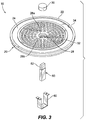
- FIG. 3 is an exploded view of the utility cover assembly of FIG. 1 ;
- FIG. 4 is a top plan view of the utility cover assembly of FIG. 1 ;
- FIG. 5 is a top plan view of another exemplary embodiment the utility cover assembly of FIG. 1 ;
- FIG. 6 is a cross sectional view of the utility cover assembly of FIG. 4 taken along line 6 - 6 ;
- FIG. 7 is top perspective view of another exemplary embodiment of a utility cover assembly according to the present disclosure.
- FIG. 8 is a top plan view of the utility cover assembly of FIG. 7 ;
- FIG. 9 is an exploded view of the utility cover assembly of FIG. 7 ;
- FIG. 10 is a bottom plan view of another exemplary embodiment of the utility cover assembly according to the present disclosure.
- FIG. 11 is a side elevation view of the utility cover assembly of FIG. 10 ;
- FIG. 12 is a top perspective view of the utility cover assembly of FIG. 1 separated from a frame;
- FIG. 13 is a bottom perspective view of the utility cover assembly and frame of FIG. 12 ;
- FIG. 14 is a side elevation view of the utility cover assembly and frame of FIG. 12 positioned for installation on a pipe.
- the present disclosure provides embodiments of utility covers and utility cover assemblies for use with automated metering equipment.
- the exemplary embodiments of the utility cover according to the present disclosure include a portion that permits electromagnetic energy, e.g., radio frequency (RF) signals, to pass through the utility cover with limited or no attenuation.
- RF radio frequency
- the exemplary embodiments of the of the utility cover assemblies according to the present disclosure include a utility cover and an electronic module capable of transmitting and/or receiving electromagnetic signals, such as an RF transmitter/receiver module, positioned in close proximity to the utility cover.
- the utility cover assemblies as described herein may be utilized to cover, for example, utility meters and/or utility valves including water, gas and electric meters and gas and water valves.
- the utility cover assemblies according to the present disclosure provide the capability to interact or communicate with meters or valves below grade without having to remove the utility cover enclosing the meter or valve, while also providing traditional utility cover functionality.
- the utility cover is comprised of a main body having a window and a plug that fits into and seals the window.
- the plug is made of a material that is substantially transparent to electromagnetic energy, e.g., an RF transparent material.
- the utility cover assembly is comprised of a utility cover having a body, a window in the body and a plug that fits into and seals the window, and an electronic module secured to the body in close proximity to the window that is capable of transmitting and/or receiving electromagnetic signals.
- the utility cover assembly 10 includes a utility cover 20 and an electronic module 50 secured to the utility cover with a mounting bracket 60 .
- the utility cover 20 includes a body 22 having an upper side 24 and a lower side 26 .
- the body 22 also includes one or more windows 28 and one or more plugs 30 where one plug fills at least a portion of one window 28 .
- the body 22 has one window 28 and one plug 30 .
- the body 22 has multiple windows 28 and multiple plugs 30 , such as four windows and four plugs.
- the body 22 may be circular in shape, square in shape, rectangular in shape or any other shape, and is dimensioned to fit within a frame that typically is secured to a pipe or enclosure.
- the body 22 is made of a rigid material sufficient to support pedestrian and/or vehicle traffic. Examples of suitable materials include cast iron, steel, and aluminum.
- the body 22 is circular in shape and has a diameter dimensioned to fit within a circular frame such as, for example, a cast iron frame 100 , seen in FIG. 12 .
- the upper side 24 of the body may include one or more slip resistant members 32 .
- the slip resistant member or members 32 may comprise, for example, treads shown in FIG. 1 , anti-slip paints, anti-slip tapes, or other anti-slip materials or structures.
- the body 22 may also include a channel 34 or other opening in which a tool may be inserted in order to lift the utility cover 20 .
- the one or more windows 28 in the body 22 may be circular in shape (seen in FIGS. 4 and 7 ), rectangular in shape (seen in FIG. 5 ), square in shape or any other shape, and are dimensioned to provide a window through which electromagnetic energy may pass.
- the one or more windows 28 in the body 22 may be positioned at any location on the body. In the embodiment shown in FIGS. 1-4 , the window 28 is a circular opening in a central area of the body 22 .
- the window 28 may have outer periphery dimension 28 a , e.g., diameter, at the upper side 24 of the body 22 and inner periphery dimension 28 b , e.g., diameter, at the lower side 26 of the body, where the outer periphery dimension 28 a is larger than the inner periphery dimension 28 b .
- the window 28 may have the same periphery dimension throughout.
- each of the multiple windows 28 is a circular opening with one window located in a central area of the body 22 and the remaining windows located in an area between the central area of the body 22 and an outer edge of the body 22 .
- Each window 28 in this embodiment may be the same as the window described above.
- each window 28 may have outer periphery dimension 28 a , e.g., diameter, at the upper side 24 of the body 22 and inner periphery dimension 28 b , e.g., diameter, at the lower side 26 of the body, where the outer periphery dimension 28 a is larger than the inner periphery dimension 28 b .
- each window 28 may have the same periphery dimension throughout.
- the lower side 26 of the body 22 may include a rigid apron 36 that surrounds the window 28 in the central area of the body 22 to provide structural stability to the body in the area of the window.
- One or more ribs 38 may extend radially from the apron 36 to form a hub-and-spoke like structure that also provide structural stability to the body 22 in the area of the window 28 .
- the apron 36 and ribs 38 can be integrally formed into the body 22 , or the apron 36 and ribs 38 can be secured to the body by for example welds or mechanical fasteners.
- the apron 36 and ribs 38 can be made of a rigid material sufficient to support pedestrian and/or vehicle traffic on the utility cover 20 .
- suitable materials include cast iron, steel, and aluminum.
- the present disclosure also contemplates other configurations for the lower side 26 of the body 22 .
- the lower side 26 of the body 22 may include a grid pattern instead of the above-described hub and spoke pattern.
- the electronic module 50 may comprise a radio receiver and/or transmitter, a power source such as a battery and associated electronic circuitry for processing information and transmitting and/or receiving radio signals through the cover.
- the electronic module 50 may be a Itron ERT module for AMR (Automated Meter Reading) system. Itron is located at 2111 N Molter Road Liberty Lakes, Wash. 99019.
- other types of electronic modules 50 may be used depending on a particular application, for example, Badger E-Series ultrasonic monitors. Badger is located at 4545 W Brown Deer Road, Milwaukee, Wis. 53224.
- the Aclara Star water solutions, and Sensus M520 may also be used for electronic module 50 .
- a distal end 52 of the electronic module 50 is positioned within the window 28 so that the distal end 52 is proximate the inner diameter 28 b of the window.
- the electronic module 50 is then secured to the lower side 26 of the body 22 using a mounting bracket 60 that is, in this exemplary embodiment, secured to the apron 36 via screws.
- a mounting bracket 60 that is, in this exemplary embodiment, secured to the apron 36 via screws.
- the electronic module 50 has a length that extends below the apron 36 so that the bracket 60 is configured as a U-shaped type bracket where the electronic module 50 is nested within the U-shape bracket 60 and the bracket 60 is secured to the apron 36 .
- the electronic module 50 has a length that does not extend below the ribs 38 so that the bracket 60 is configured as a flat plate where the plate contacts the electronic module 50 and the bracket 60 is secured across two ribs 38 as shown.
- Each plug 30 for each window 28 fits into the outer periphery dimension 28 a of the window 28 and seals the window to prevent moisture from passing through the utility cover 20 .
- Each plug 30 is made of a material that is substantially transparent to electromagnetic energy, e.g., an RF transparent material, that can withstand pedestrian and/or vehicle traffic and as well as wear or damage caused by environmental conditions. Examples of materials that are substantially transparent to electromagnetic energy include fiberglass composite, polymer concrete, polyethylene, polypropylene, and vulcanized rubber.
- the utility cover 20 of the utility cover assembly 10 may come in a number of different shapes and dimensions to fit within a frame, such as frame 100 seen in FIGS. 12-14 , that typically is mounted on or secured to a pipe or enclosure.
- the frame 100 is a circular frame that matches the circular utility cover 20 .
- the frame 100 has an upper ring portion 102 and a lower ring portion 104 .
- the upper ring portion 102 of the frame 100 in the embodiment shown in FIGS. 12-13 is circular so that the circular utility cover 20 can fit within opening 106 in the upper ring portion 102 of the frame.
- the utility cover 20 is supported within the upper ring portion 102 by lip 108 around the inner perimeter of the upper ring portion 102 .
- the lip 108 is located so that the upper side 24 of the body 22 of the utility cover 20 is at or near a top edge 110 of the frame 100 when installed.
- the lower ring portion 104 of the frame 100 is in this exemplary embodiment circular in shape to match the shape of the upper ring portion 102 , and has an opening that matches the opening 106 .
- the lower ring portion 104 has a larger outer periphery than the upper ring portion 102 .
- the lower ring portion 104 may have a different shape than the upper ring portion 102 depending upon the shape of the pipe or enclosure.
- the larger outer periphery allows the frame 100 to rest on an upper edge 132 of pipe 130 , seen in FIG.
- the pipe 130 may allow access to a valve or meter provided below ground level.
- the upper edge 132 of the pipe 130 may be provided at or just below ground level so that when the utility cover 20 is inserted into the frame 100 the upper side 24 of the body 22 remains at or above ground level.
- the utility cover and utility cover assemblies as described herein may be used as utility meter covers (e.g., for water, gas or electric meters), and/or utility valve covers (e.g., for water or gas valves). Utility cover assemblies as described herein may be used anywhere within a metering infrastructure where electromagnetic or acoustic signal transmission and/or reception is utilized. Other exemplary metering or flow measurement systems that may be used with the utility cover assemblies described herein include, for example, metering or flow measurement systems including the Orion® Endpoint system by Badger and metering or sensing systems including the Smartpoint® 520M pit set module by Sensus Inc.
Landscapes
- Engineering & Computer Science (AREA)
- Physics & Mathematics (AREA)
- General Physics & Mathematics (AREA)
- Computer Networks & Wireless Communication (AREA)
- General Engineering & Computer Science (AREA)
- Mechanical Engineering (AREA)
- Casings For Electric Apparatus (AREA)
- Underground Structures, Protecting, Testing And Restoring Foundations (AREA)
Abstract
Description
Claims (20)
Priority Applications (1)
| Application Number | Priority Date | Filing Date | Title |
|---|---|---|---|
| US16/338,217 US11221233B2 (en) | 2016-10-06 | 2017-09-21 | Utility cover for use with automated metering equipment |
Applications Claiming Priority (3)
| Application Number | Priority Date | Filing Date | Title |
|---|---|---|---|
| US201662405094P | 2016-10-06 | 2016-10-06 | |
| PCT/US2017/052637 WO2018067315A1 (en) | 2016-10-06 | 2017-09-21 | Utility cover for use with automated metering equipment |
| US16/338,217 US11221233B2 (en) | 2016-10-06 | 2017-09-21 | Utility cover for use with automated metering equipment |
Related Parent Applications (1)
| Application Number | Title | Priority Date | Filing Date |
|---|---|---|---|
| PCT/US2017/052637 A-371-Of-International WO2018067315A1 (en) | 2016-10-06 | 2017-09-21 | Utility cover for use with automated metering equipment |
Related Child Applications (1)
| Application Number | Title | Priority Date | Filing Date |
|---|---|---|---|
| US17/568,579 Continuation US20220128378A1 (en) | 2016-10-06 | 2022-01-04 | Utility cover for use with automated metering equipment |
Publications (2)
| Publication Number | Publication Date |
|---|---|
| US20190226874A1 US20190226874A1 (en) | 2019-07-25 |
| US11221233B2 true US11221233B2 (en) | 2022-01-11 |
Family
ID=61831227
Family Applications (2)
| Application Number | Title | Priority Date | Filing Date |
|---|---|---|---|
| US16/338,217 Active 2038-03-27 US11221233B2 (en) | 2016-10-06 | 2017-09-21 | Utility cover for use with automated metering equipment |
| US17/568,579 Abandoned US20220128378A1 (en) | 2016-10-06 | 2022-01-04 | Utility cover for use with automated metering equipment |
Family Applications After (1)
| Application Number | Title | Priority Date | Filing Date |
|---|---|---|---|
| US17/568,579 Abandoned US20220128378A1 (en) | 2016-10-06 | 2022-01-04 | Utility cover for use with automated metering equipment |
Country Status (2)
| Country | Link |
|---|---|
| US (2) | US11221233B2 (en) |
| WO (1) | WO2018067315A1 (en) |
Cited By (1)
| Publication number | Priority date | Publication date | Assignee | Title |
|---|---|---|---|---|
| USD1053384S1 (en) * | 2021-09-21 | 2024-12-03 | National Diversified Sales, Inc. | Cover |
Families Citing this family (4)
| Publication number | Priority date | Publication date | Assignee | Title |
|---|---|---|---|---|
| GB2575068A (en) * | 2018-06-27 | 2020-01-01 | Iwireless Solutions Ltd | Enclosure cover with an antenna |
| US11171402B2 (en) * | 2018-12-21 | 2021-11-09 | HYDRO-QUéBEC | Wireless telecommunication system for an equipment in an underground structure |
| USD1050922S1 (en) | 2022-11-18 | 2024-11-12 | Stephen C. Way | Water meter box plug |
| US20250231058A1 (en) * | 2024-01-11 | 2025-07-17 | Hubbell Incorporated | Meter transmission unit mounting device |
Citations (36)
| Publication number | Priority date | Publication date | Assignee | Title |
|---|---|---|---|---|
| US317153A (en) | 1885-05-05 | Self-locking man-hole cover for sewers | ||
| US2608085A (en) | 1947-07-23 | 1952-08-26 | Alfred B Castle | Locking device |
| US2697389A (en) | 1949-04-11 | 1954-12-21 | Earle D Heckman | Lock type manhole cover |
| US3530696A (en) | 1968-03-07 | 1970-09-29 | Christy Concrete Products Inc | Gravity latch for box lid |
| US4834574A (en) | 1987-07-23 | 1989-05-30 | Bowman Harold M | Utility cover extension |
| US4969771A (en) | 1987-07-23 | 1990-11-13 | Bowman Harold M | Manhole cover support having enhanced grip |
| US5123776A (en) | 1991-01-31 | 1992-06-23 | Advanced Drainage Systems, Inc. | Plastic fillable manhole cover with penetrating handles |
| US5240346A (en) | 1992-02-05 | 1993-08-31 | Yin Chun Chou | Manhole having a splayed rib ring formed at underside of the lid thereof |
| US5583492A (en) | 1993-09-24 | 1996-12-10 | Hitachi Cable, Ltd. | Method and apparatus for monitoring inside a manhole |
| JPH1161867A (en) | 1997-08-08 | 1999-03-05 | Kubota Corp | Manhole cover for wireless communication |
| US20010011009A1 (en) | 1996-04-22 | 2001-08-02 | Toshio Harada | Underground information communication system and related manhole cover |
| US6414605B1 (en) | 1998-09-02 | 2002-07-02 | Schlumberger Resource Management Services, Inc. | Utility meter pit lid mounted antenna assembly and method |
| US20030178425A1 (en) * | 2002-03-21 | 2003-09-25 | Mckinnon James Stephen | Meter box lid and holder |
| US20040042849A1 (en) | 2002-08-15 | 2004-03-04 | Bescal, Inc. | Utilities access closure |
| KR200406184Y1 (en) | 2005-10-14 | 2006-01-20 | 황종헌 | Electric shock prevention cap for manhole cover and frame member |
| CN2764821Y (en) | 2004-11-29 | 2006-03-15 | 广州市路安复合材料构件有限公司 | Well cover made of concrete composite material |
| KR100566663B1 (en) | 2005-11-02 | 2006-04-03 | 주식회사 대한콘설탄트 | Electric manhole to prevent electric shock accident |
| KR20070011703A (en) | 2005-07-21 | 2007-01-25 | 신운철 | Insulating Manhole Structure |
| US20080050175A1 (en) | 2006-08-25 | 2008-02-28 | Gmi Composites Inc. | Reinforced composite manhole cover assembly |
| US20080074283A1 (en) | 2006-09-25 | 2008-03-27 | Jeff Verkleeren | Utility meter antenna for ground mounted meter boxes |
| US7619878B1 (en) | 2007-07-16 | 2009-11-17 | Nicor, Inc. | Meter cover for automated meter reading |
| US20100019912A1 (en) | 2008-07-22 | 2010-01-28 | Ussi, Llc | Manhole security system |
| US20110006182A1 (en) * | 2009-07-13 | 2011-01-13 | The Ford Meter Box Company, Inc. | Lid plug and bracket |
| US20120098710A1 (en) | 2006-11-03 | 2012-04-26 | Smartsynch, Inc. | Forward Throw Antenna Utility Meter with Antenna Mounting Bracket |
| US20120114414A1 (en) | 2009-07-13 | 2012-05-10 | Jung Sik Jang | Manhole cover and method for manufacturing same |
| US8258977B1 (en) | 2007-11-27 | 2012-09-04 | EmNet, LLC | Manhole cover with signal transmitter |
| US20130011194A1 (en) | 2011-07-06 | 2013-01-10 | Thomas Lorenz Industrietechnik GmbH/Co. KG | Manhole cover optimized for manufacturing |
| US20130212945A1 (en) | 2010-10-07 | 2013-08-22 | Mcgard Llc | Manhole Security Cover |
| US20130301190A1 (en) | 2012-05-09 | 2013-11-14 | Eric Metzger | Kit For Installation Of Water Meter Reading Equipment In Three Configurations |
| US20140144067A1 (en) | 2012-11-28 | 2014-05-29 | Itzhak Shefer | See-through manhole cover |
| US20140268506A1 (en) | 2013-03-15 | 2014-09-18 | Trumbull Manufacturing, Inc. | Utility meter box and meter box cover |
| US20150122959A1 (en) | 2013-10-31 | 2015-05-07 | Jeffrey A. Cook | Amr/ami pit lid antenna bracket |
| US20160069039A1 (en) | 2014-09-05 | 2016-03-10 | Hubbell Incorporated | Hybrid utility cover |
| US20160094897A1 (en) | 2014-09-26 | 2016-03-31 | Yoram Kenig | High Output Integrated Utility Meter Reporting System |
| US20170023612A1 (en) | 2015-07-22 | 2017-01-26 | Iometers, LLC | Meter Box Lid |
| US20180013934A1 (en) * | 2016-07-07 | 2018-01-11 | Google Inc. | Magnetic Mount Assembly of a Camera |
-
2017
- 2017-09-21 WO PCT/US2017/052637 patent/WO2018067315A1/en not_active Ceased
- 2017-09-21 US US16/338,217 patent/US11221233B2/en active Active
-
2022
- 2022-01-04 US US17/568,579 patent/US20220128378A1/en not_active Abandoned
Patent Citations (38)
| Publication number | Priority date | Publication date | Assignee | Title |
|---|---|---|---|---|
| US317153A (en) | 1885-05-05 | Self-locking man-hole cover for sewers | ||
| US2608085A (en) | 1947-07-23 | 1952-08-26 | Alfred B Castle | Locking device |
| US2697389A (en) | 1949-04-11 | 1954-12-21 | Earle D Heckman | Lock type manhole cover |
| US3530696A (en) | 1968-03-07 | 1970-09-29 | Christy Concrete Products Inc | Gravity latch for box lid |
| US4834574A (en) | 1987-07-23 | 1989-05-30 | Bowman Harold M | Utility cover extension |
| US4969771A (en) | 1987-07-23 | 1990-11-13 | Bowman Harold M | Manhole cover support having enhanced grip |
| US5123776A (en) | 1991-01-31 | 1992-06-23 | Advanced Drainage Systems, Inc. | Plastic fillable manhole cover with penetrating handles |
| US5240346A (en) | 1992-02-05 | 1993-08-31 | Yin Chun Chou | Manhole having a splayed rib ring formed at underside of the lid thereof |
| US5583492A (en) | 1993-09-24 | 1996-12-10 | Hitachi Cable, Ltd. | Method and apparatus for monitoring inside a manhole |
| US20010011009A1 (en) | 1996-04-22 | 2001-08-02 | Toshio Harada | Underground information communication system and related manhole cover |
| JPH1161867A (en) | 1997-08-08 | 1999-03-05 | Kubota Corp | Manhole cover for wireless communication |
| US6414605B1 (en) | 1998-09-02 | 2002-07-02 | Schlumberger Resource Management Services, Inc. | Utility meter pit lid mounted antenna assembly and method |
| US20030178425A1 (en) * | 2002-03-21 | 2003-09-25 | Mckinnon James Stephen | Meter box lid and holder |
| US20070194493A1 (en) | 2002-08-15 | 2007-08-23 | Bescal, Inc. | Utilities Access Closure |
| US20040042849A1 (en) | 2002-08-15 | 2004-03-04 | Bescal, Inc. | Utilities access closure |
| CN2764821Y (en) | 2004-11-29 | 2006-03-15 | 广州市路安复合材料构件有限公司 | Well cover made of concrete composite material |
| KR20070011703A (en) | 2005-07-21 | 2007-01-25 | 신운철 | Insulating Manhole Structure |
| KR200406184Y1 (en) | 2005-10-14 | 2006-01-20 | 황종헌 | Electric shock prevention cap for manhole cover and frame member |
| KR100566663B1 (en) | 2005-11-02 | 2006-04-03 | 주식회사 대한콘설탄트 | Electric manhole to prevent electric shock accident |
| US20080050175A1 (en) | 2006-08-25 | 2008-02-28 | Gmi Composites Inc. | Reinforced composite manhole cover assembly |
| US20080074283A1 (en) | 2006-09-25 | 2008-03-27 | Jeff Verkleeren | Utility meter antenna for ground mounted meter boxes |
| US20120098710A1 (en) | 2006-11-03 | 2012-04-26 | Smartsynch, Inc. | Forward Throw Antenna Utility Meter with Antenna Mounting Bracket |
| US7619878B1 (en) | 2007-07-16 | 2009-11-17 | Nicor, Inc. | Meter cover for automated meter reading |
| US8258977B1 (en) | 2007-11-27 | 2012-09-04 | EmNet, LLC | Manhole cover with signal transmitter |
| US20100019912A1 (en) | 2008-07-22 | 2010-01-28 | Ussi, Llc | Manhole security system |
| US20110006182A1 (en) * | 2009-07-13 | 2011-01-13 | The Ford Meter Box Company, Inc. | Lid plug and bracket |
| US20120114414A1 (en) | 2009-07-13 | 2012-05-10 | Jung Sik Jang | Manhole cover and method for manufacturing same |
| US20130212945A1 (en) | 2010-10-07 | 2013-08-22 | Mcgard Llc | Manhole Security Cover |
| US20130011194A1 (en) | 2011-07-06 | 2013-01-10 | Thomas Lorenz Industrietechnik GmbH/Co. KG | Manhole cover optimized for manufacturing |
| US20130301190A1 (en) | 2012-05-09 | 2013-11-14 | Eric Metzger | Kit For Installation Of Water Meter Reading Equipment In Three Configurations |
| US20140144067A1 (en) | 2012-11-28 | 2014-05-29 | Itzhak Shefer | See-through manhole cover |
| US9258992B2 (en) | 2012-11-28 | 2016-02-16 | Itzhak Shefer | See-through manhole cover |
| US20140268506A1 (en) | 2013-03-15 | 2014-09-18 | Trumbull Manufacturing, Inc. | Utility meter box and meter box cover |
| US20150122959A1 (en) | 2013-10-31 | 2015-05-07 | Jeffrey A. Cook | Amr/ami pit lid antenna bracket |
| US20160069039A1 (en) | 2014-09-05 | 2016-03-10 | Hubbell Incorporated | Hybrid utility cover |
| US20160094897A1 (en) | 2014-09-26 | 2016-03-31 | Yoram Kenig | High Output Integrated Utility Meter Reporting System |
| US20170023612A1 (en) | 2015-07-22 | 2017-01-26 | Iometers, LLC | Meter Box Lid |
| US20180013934A1 (en) * | 2016-07-07 | 2018-01-11 | Google Inc. | Magnetic Mount Assembly of a Camera |
Non-Patent Citations (3)
| Title |
|---|
| Elan Technologies Inc. Product Sheet, Comcore (R) Manhole Antenna Cover, (2 pages) 2008. |
| Hubbell Power Systems Power Sheet, "Antenna Covers" 2001. |
| International Search Report and Written Opinion mailed in PCT/US2017/052637 dated Nov. 30, 2017. |
Cited By (1)
| Publication number | Priority date | Publication date | Assignee | Title |
|---|---|---|---|---|
| USD1053384S1 (en) * | 2021-09-21 | 2024-12-03 | National Diversified Sales, Inc. | Cover |
Also Published As
| Publication number | Publication date |
|---|---|
| US20220128378A1 (en) | 2022-04-28 |
| WO2018067315A1 (en) | 2018-04-12 |
| US20190226874A1 (en) | 2019-07-25 |
Similar Documents
| Publication | Publication Date | Title |
|---|---|---|
| US20220128378A1 (en) | Utility cover for use with automated metering equipment | |
| US12019105B2 (en) | Utility cover for use with automated metering equipment | |
| US10637146B2 (en) | Through-the-lid pit antenna | |
| US6518933B2 (en) | Low profile antenna | |
| KR20070104866A (en) | Surface mounted antenna device | |
| CN105720353B (en) | A kind of antenna structure and its installation method of wireless network covering well lid | |
| WO2015156096A1 (en) | Wireless communication structure and wireless communication method | |
| US20040155826A1 (en) | Deformable antenna assembly for mounting in gaps and crevices | |
| US10240317B2 (en) | Cover assembly | |
| JP2017195559A (en) | Manhole lid with antenna | |
| JP7783263B2 (en) | Remote Sensing Devices | |
| US20120119972A1 (en) | Gsm antenna, in particular for a device using the public network | |
| KR101394071B1 (en) | Manhole | |
| EP3651267B1 (en) | Cover element with transmitter system | |
| KR200420847Y1 (en) | Surface mounted antenna device | |
| KR102314609B1 (en) | Antena Module Waterproof and Embed Structure for Smart Manhole Cover | |
| KR101936866B1 (en) | Manhole cover type antenna | |
| KR102710781B1 (en) | Piping data communication system | |
| KR200494990Y1 (en) | Height adjusting structure of casing | |
| US20250226570A1 (en) | Mechanically Mounted Traffic Rated Antenna | |
| CN103572782B (en) | Multifunctional well cover | |
| KR20170004192U (en) | Manhole Antenna | |
| JP2003034941A (en) | Antenna device for ground surface | |
| US20260056046A1 (en) | Molded meter pit frame | |
| JP3149300U (en) | Cast iron transmit / receive antenna for manhole cover |
Legal Events
| Date | Code | Title | Description |
|---|---|---|---|
| FEPP | Fee payment procedure |
Free format text: ENTITY STATUS SET TO UNDISCOUNTED (ORIGINAL EVENT CODE: BIG.); ENTITY STATUS OF PATENT OWNER: LARGE ENTITY |
|
| STPP | Information on status: patent application and granting procedure in general |
Free format text: APPLICATION UNDERGOING PREEXAM PROCESSING |
|
| STPP | Information on status: patent application and granting procedure in general |
Free format text: APPLICATION DISPATCHED FROM PREEXAM, NOT YET DOCKETED |
|
| STPP | Information on status: patent application and granting procedure in general |
Free format text: DOCKETED NEW CASE - READY FOR EXAMINATION |
|
| AS | Assignment |
Owner name: HUBBELL INCORPORATED, CONNECTICUT Free format text: ASSIGNMENT OF ASSIGNORS INTEREST;ASSIGNOR:SLATER, ERIC M.;REEL/FRAME:052069/0639 Effective date: 20200310 |
|
| STPP | Information on status: patent application and granting procedure in general |
Free format text: NON FINAL ACTION MAILED |
|
| STPP | Information on status: patent application and granting procedure in general |
Free format text: RESPONSE TO NON-FINAL OFFICE ACTION ENTERED AND FORWARDED TO EXAMINER |
|
| STPP | Information on status: patent application and granting procedure in general |
Free format text: FINAL REJECTION MAILED |
|
| STPP | Information on status: patent application and granting procedure in general |
Free format text: RESPONSE AFTER FINAL ACTION FORWARDED TO EXAMINER |
|
| STPP | Information on status: patent application and granting procedure in general |
Free format text: ADVISORY ACTION MAILED |
|
| STPP | Information on status: patent application and granting procedure in general |
Free format text: DOCKETED NEW CASE - READY FOR EXAMINATION |
|
| STPP | Information on status: patent application and granting procedure in general |
Free format text: NOTICE OF ALLOWANCE MAILED -- APPLICATION RECEIVED IN OFFICE OF PUBLICATIONS |
|
| STPP | Information on status: patent application and granting procedure in general |
Free format text: PUBLICATIONS -- ISSUE FEE PAYMENT VERIFIED |
|
| STCF | Information on status: patent grant |
Free format text: PATENTED CASE |
|
| MAFP | Maintenance fee payment |
Free format text: PAYMENT OF MAINTENANCE FEE, 4TH YEAR, LARGE ENTITY (ORIGINAL EVENT CODE: M1551); ENTITY STATUS OF PATENT OWNER: LARGE ENTITY Year of fee payment: 4 |