US11221006B2 - Device for wetting a plurality of threads, and metering pump for such a device - Google Patents
Device for wetting a plurality of threads, and metering pump for such a device Download PDFInfo
- Publication number
- US11221006B2 US11221006B2 US16/476,643 US201816476643A US11221006B2 US 11221006 B2 US11221006 B2 US 11221006B2 US 201816476643 A US201816476643 A US 201816476643A US 11221006 B2 US11221006 B2 US 11221006B2
- Authority
- US
- United States
- Prior art keywords
- planetary gear
- housing
- pump
- planet gears
- gear set
- Prior art date
- Legal status (The legal status is an assumption and is not a legal conclusion. Google has not performed a legal analysis and makes no representation as to the accuracy of the status listed.)
- Active, expires
Links
Images


Classifications
-
- F—MECHANICAL ENGINEERING; LIGHTING; HEATING; WEAPONS; BLASTING
- F04—POSITIVE - DISPLACEMENT MACHINES FOR LIQUIDS; PUMPS FOR LIQUIDS OR ELASTIC FLUIDS
- F04C—ROTARY-PISTON, OR OSCILLATING-PISTON, POSITIVE-DISPLACEMENT MACHINES FOR LIQUIDS; ROTARY-PISTON, OR OSCILLATING-PISTON, POSITIVE-DISPLACEMENT PUMPS
- F04C2/00—Rotary-piston machines or pumps
- F04C2/08—Rotary-piston machines or pumps of intermeshing-engagement type, i.e. with engagement of co-operating members similar to that of toothed gearing
- F04C2/082—Details specially related to intermeshing engagement type machines or pumps
- F04C2/084—Toothed wheels
-
- D—TEXTILES; PAPER
- D06—TREATMENT OF TEXTILES OR THE LIKE; LAUNDERING; FLEXIBLE MATERIALS NOT OTHERWISE PROVIDED FOR
- D06B—TREATING TEXTILE MATERIALS USING LIQUIDS, GASES OR VAPOURS
- D06B23/00—Component parts, details, or accessories of apparatus or machines, specially adapted for the treating of textile materials, not restricted to a particular kind of apparatus, provided for in groups D06B1/00 - D06B21/00
- D06B23/20—Arrangements of apparatus for treating processing-liquids, -gases or -vapours, e.g. purification, filtration or distillation
- D06B23/205—Arrangements of apparatus for treating processing-liquids, -gases or -vapours, e.g. purification, filtration or distillation for adding or mixing constituents of the treating material
-
- D—TEXTILES; PAPER
- D01—NATURAL OR MAN-MADE THREADS OR FIBRES; SPINNING
- D01D—MECHANICAL METHODS OR APPARATUS IN THE MANUFACTURE OF ARTIFICIAL FILAMENTS, THREADS, FIBRES, BRISTLES OR RIBBONS
- D01D5/00—Formation of filaments, threads, or the like
- D01D5/08—Melt spinning methods
- D01D5/096—Humidity control, or oiling, of filaments, threads or the like, leaving the spinnerettes
-
- D—TEXTILES; PAPER
- D06—TREATMENT OF TEXTILES OR THE LIKE; LAUNDERING; FLEXIBLE MATERIALS NOT OTHERWISE PROVIDED FOR
- D06B—TREATING TEXTILE MATERIALS USING LIQUIDS, GASES OR VAPOURS
- D06B5/00—Forcing liquids, gases or vapours through textile materials to effect treatment, e.g. washing, dyeing, bleaching, sizing impregnating
- D06B5/02—Forcing liquids, gases or vapours through textile materials to effect treatment, e.g. washing, dyeing, bleaching, sizing impregnating through moving materials of indefinite length
- D06B5/06—Forcing liquids, gases or vapours through textile materials to effect treatment, e.g. washing, dyeing, bleaching, sizing impregnating through moving materials of indefinite length through yarns, threads or filaments
-
- F—MECHANICAL ENGINEERING; LIGHTING; HEATING; WEAPONS; BLASTING
- F04—POSITIVE - DISPLACEMENT MACHINES FOR LIQUIDS; PUMPS FOR LIQUIDS OR ELASTIC FLUIDS
- F04C—ROTARY-PISTON, OR OSCILLATING-PISTON, POSITIVE-DISPLACEMENT MACHINES FOR LIQUIDS; ROTARY-PISTON, OR OSCILLATING-PISTON, POSITIVE-DISPLACEMENT PUMPS
- F04C13/00—Adaptations of machines or pumps for special use, e.g. for extremely high pressures
-
- F—MECHANICAL ENGINEERING; LIGHTING; HEATING; WEAPONS; BLASTING
- F04—POSITIVE - DISPLACEMENT MACHINES FOR LIQUIDS; PUMPS FOR LIQUIDS OR ELASTIC FLUIDS
- F04C—ROTARY-PISTON, OR OSCILLATING-PISTON, POSITIVE-DISPLACEMENT MACHINES FOR LIQUIDS; ROTARY-PISTON, OR OSCILLATING-PISTON, POSITIVE-DISPLACEMENT PUMPS
- F04C2/00—Rotary-piston machines or pumps
- F04C2/08—Rotary-piston machines or pumps of intermeshing-engagement type, i.e. with engagement of co-operating members similar to that of toothed gearing
- F04C2/12—Rotary-piston machines or pumps of intermeshing-engagement type, i.e. with engagement of co-operating members similar to that of toothed gearing of other than internal-axis type
- F04C2/14—Rotary-piston machines or pumps of intermeshing-engagement type, i.e. with engagement of co-operating members similar to that of toothed gearing of other than internal-axis type with toothed rotary pistons
-
- F—MECHANICAL ENGINEERING; LIGHTING; HEATING; WEAPONS; BLASTING
- F16—ENGINEERING ELEMENTS AND UNITS; GENERAL MEASURES FOR PRODUCING AND MAINTAINING EFFECTIVE FUNCTIONING OF MACHINES OR INSTALLATIONS; THERMAL INSULATION IN GENERAL
- F16H—GEARING
- F16H1/00—Toothed gearings for conveying rotary motion
- F16H1/28—Toothed gearings for conveying rotary motion with gears having orbital motion
-
- D—TEXTILES; PAPER
- D06—TREATMENT OF TEXTILES OR THE LIKE; LAUNDERING; FLEXIBLE MATERIALS NOT OTHERWISE PROVIDED FOR
- D06B—TREATING TEXTILE MATERIALS USING LIQUIDS, GASES OR VAPOURS
- D06B3/00—Passing of textile materials through liquids, gases or vapours to effect treatment, e.g. washing, dyeing, bleaching, sizing, impregnating
- D06B3/04—Passing of textile materials through liquids, gases or vapours to effect treatment, e.g. washing, dyeing, bleaching, sizing, impregnating of yarns, threads or filaments
- D06B3/045—Passing of textile materials through liquids, gases or vapours to effect treatment, e.g. washing, dyeing, bleaching, sizing, impregnating of yarns, threads or filaments in a tube or a groove
-
- F—MECHANICAL ENGINEERING; LIGHTING; HEATING; WEAPONS; BLASTING
- F04—POSITIVE - DISPLACEMENT MACHINES FOR LIQUIDS; PUMPS FOR LIQUIDS OR ELASTIC FLUIDS
- F04C—ROTARY-PISTON, OR OSCILLATING-PISTON, POSITIVE-DISPLACEMENT MACHINES FOR LIQUIDS; ROTARY-PISTON, OR OSCILLATING-PISTON, POSITIVE-DISPLACEMENT PUMPS
- F04C15/00—Component parts, details or accessories of machines, pumps or pumping installations, not provided for in groups F04C2/00 - F04C14/00
- F04C15/0057—Driving elements, brakes, couplings, transmission specially adapted for machines or pumps
- F04C15/008—Prime movers
-
- F—MECHANICAL ENGINEERING; LIGHTING; HEATING; WEAPONS; BLASTING
- F04—POSITIVE - DISPLACEMENT MACHINES FOR LIQUIDS; PUMPS FOR LIQUIDS OR ELASTIC FLUIDS
- F04C—ROTARY-PISTON, OR OSCILLATING-PISTON, POSITIVE-DISPLACEMENT MACHINES FOR LIQUIDS; ROTARY-PISTON, OR OSCILLATING-PISTON, POSITIVE-DISPLACEMENT PUMPS
- F04C2220/00—Application
- F04C2220/24—Application for metering throughflow
-
- F—MECHANICAL ENGINEERING; LIGHTING; HEATING; WEAPONS; BLASTING
- F04—POSITIVE - DISPLACEMENT MACHINES FOR LIQUIDS; PUMPS FOR LIQUIDS OR ELASTIC FLUIDS
- F04C—ROTARY-PISTON, OR OSCILLATING-PISTON, POSITIVE-DISPLACEMENT MACHINES FOR LIQUIDS; ROTARY-PISTON, OR OSCILLATING-PISTON, POSITIVE-DISPLACEMENT PUMPS
- F04C2240/00—Components
- F04C2240/70—Use of multiplicity of similar components; Modular construction
Definitions
- the invention relates to a device for wetting multiple threads, as disclosed herein, and to a dosing pump, in particular for use in a device for wetting threads.
- the threads In the production and processing of synthetic threads, it is generally known for the threads to be wetted with a fluid.
- a fluid For example, during the production of synthetic threads, after the melt spinning, the fluid is utilized to ensure the cohesion of the filaments of the thread.
- the fluid is utilized for cooling a previously warmed thread. Irrespective of whether the fluid serves for the preparation or for the cooling of the threads, it is necessary for the fluid to be fed to the running threads in continuous fashion with high dosing accuracy.
- groups of threads are guided and treated in parallel adjacent to one another, such that the fluid must be fed in equal dosing quantities in parallel at multiple wetting means.
- a generic device for wetting multiple threads and a generic dosing pump are known for example from EP 1 039 011 A2.
- the dosing flows of a fluid are generated by multiple conveying means of a dosing pump.
- the conveying means are formed by toothed gear pairings of a planetary gear set, wherein multiple planetary gear sets are held between housing plates.
- each planetary gear set is formed from a sun gear and multiple planet gears, wherein the sun gear is arranged on a drive shaft, and wherein the planet gears are guided by axles mounted rotatably in the housing plates.
- Formed on the housing plates are the pump outlets, which are connected in each case to the outlet zones of the planetary gear sets.
- Each of the pump outlets is assigned a wetting means, which are connected by means of separate conveying lines to the dosing pump.
- the invention is based on the realization that a dead volume in a gearwheel pairing is influenced significantly by a tip clearance that arises between the toothed gears and a housing wall.
- the planetary gear sets are, according to the invention, each guided freely by a centering plate between adjacent housing plates.
- the invention thus intentionally dispenses with journal guidance of the planet gears, which furthermore constitute additional dead spaces at the housing plates.
- the invention utilizes a passage opening formed in the planet gears to feed the fluid to the respective toothed gear pairing. Constant flushing around the planet gears is thus realized, which prevents a deposition of fluid in the axial gaps of the planetary gear set.
- the device according to the invention is thus particularly suitable for feeding oil-containing fluid emulsions for wetting multiple threads in dosed fashion to the individual threads. It is thus advantageously possible for extremely low dosing flow rates in the range from 0.05 ml/min to 5 ml/min to be realized for wetting a thread.
- the fluid is fed in the same way to the toothed gear pairings at the planetary gear set.
- the refinement of the invention is particularly preferred in which the channel system has multiple housing bores in the housing plates, which housing bores open into the passage openings of the planet gears of the planetary gear set.
- the housing bores have multiple inlet bores in one of the housing plates and multiple axial distribution bores in the housing plates arranged between adjacent planetary gear sets. It is thus possible for the fluid to be fed in an axial direction to each of the planetary gear sets directly through the passage openings of the planet gears.
- the filling of the run-in zones of the planetary gear sets is advantageously ensured by means of multiple distribution grooves which, in one advantageous refinement of the invention, are formed on a side of the housing plates facing toward the planet gear.
- the distribution grooves extend in each case between one of the passage openings of the planet gears and one of several run-in zones of the planetary gear sets.
- the refinement of the invention is particularly preferred in which the planetary gear sets are connected to a drive shaft and in which the drive shaft is coupled to a stepper motor. It is thus possible for even low rotational speeds to be set with high precision and uniformity.
- a particularly compact unit can be formed by virtue of the stepper motor being held with a housing on the outer housing plate of the dosing pump and on which the drive shaft is connected directly to a rotor of the stepper motor.
- the drive shaft of the planetary gear sets thus acts directly as motor shaft of the stepper motor.
- the refinement of the invention is particularly advantageous in which the pump outlets, assigned to one of the planetary gear sets, in one of the housing plates are formed in each case as a plug-in connector. It is thus possible, for example, for hose lines to be held directly on the pump outlets by means of a simple plug-type connection. Cumbersome threaded fasteners, which require a high level of installation effort, can thus be omitted.
- the dosing pump according to the invention is thus particularly suitable for generating a relatively large multiplicity of uniformly generated dosing flows of the fluid.
- the planetary gear sets are in this case preferably designed with multiple planet gears in order to realize a high density of the pump outlets per housing plate.
- the number of planet gears per planetary gear set lies in the range from 2 to 6 planet gears.
- FIG. 1 schematically shows a view of an exemplary embodiment of the device according to the invention for wetting multiple threads
- FIG. 2 schematically shows a longitudinal sectional view of the dosing pump according to the invention of the exemplary embodiment from FIG. 1
- FIG. 3 schematically shows a further longitudinal sectional view of the dosing pump according to the invention of the exemplary embodiment from FIG. 1
- FIG. 4 schematically shows a cross-sectional view of the dosing pump according to the invention of the exemplary embodiment from FIG. 1
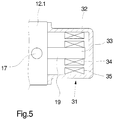
- FIG. 5 schematically shows a cross-sectional view of a stepper motor for driving a dosing pump according to the invention
- FIG. 6 schematically shows a longitudinal sectional view of a further exemplary embodiment of the dosing pump according to the invention
- FIG. 7 schematically shows a further longitudinal sectional view of the exemplary embodiment from FIG. 6
- FIG. 8 schematically shows a cross-sectional view of the exemplary embodiment from FIG. 6
- FIG. 1 schematically illustrates an exemplary embodiment of a device according to the invention for wetting multiple threads.
- the exemplary embodiment has multiple wetting means 1 . 1 to 1 . 6 .
- the number of wetting means is an example.
- the number of wetting means is basically coordinated with the number of threads which, adjacent to one another in parallel, are to be wetted simultaneously as a group.
- a wetting body 2 is shown which has an open wetting groove 3 at one side.
- a dosing bore 4 opens out in the wetting groove 3 .
- the dosing bore 4 is connected to one of the conveying lines 5 . 1 to 5 . 6 .
- the wetting means illustrated in FIG. 1 in the form of a wetting body 2 is an example. It is basically possible for such wetting means to be utilized for the preparation of a thread or for example for the cooling of a thread.
- the wetting means are designed correspondingly in accordance with the usage situation. For example, for the cooling of threads, elongate wetting grooves are used to which the fluid is fed in a run-in region.
- Each of the wetting means 1 . 1 to 1 . 6 is connected via a separate conveying line 5 . 1 to 5 . 6 to a dosing pump 6 .
- the dosing pump 6 has a multiplicity of conveying means, to which in each case one of several pump outlets 7 . 1 to 7 . 6 are assigned.
- the conveying lines 5 . 1 to 5 . 6 are connected to the pump outlets 7 . 1 to 7 . 6 .
- the dosing pump 6 is connected by means of a pump inlet 17 and an inflow line 30 to a fluid accumulator (not illustrated here) which holds a fluid provided for the wetting.
- the dosing pump 6 is driven by means of an electric motor 31 , which could be designed for example as a stepper motor.
- FIGS. 2 and 3 each show a longitudinal sectional view of the dosing pump 6
- FIG. 4 shows a cross section of the dosing pump 6 .
- the dosing pump 6 is composed of multiple housing plates 12 . 1 to 12 . 4 , which in this case have a circular cross section.
- the housing plates 12 . 1 to 12 . 4 enclose between them multiple planetary gear sets 8 . 1 to 8 . 3 , which are each enclosed within a centering plate 11 . 1 to 11 . 3 .
- the housing plates 12 . 1 to 12 . 4 and the interposed centering plates 11 . 1 to 11 . 3 are held together in pressure-tight fashion.
- Each of the planetary gear sets 8 . 1 to 8 . 3 forms multiple conveying means, which will be described in more detail below on the basis of the illustration in FIG. 4 .
- one of the planetary gear sets in this case the planetary gear set 8 . 1 , has two outer planet gears 9 . 1 and 9 . 2 and a sun gear 10 arranged in the center.
- the sun gear 10 is held by means of a shaft-hub connection 29 on the circumference of a drive shaft 19 .
- the planet gears 9 . 1 and 9 . 2 are arranged oppositely to both sides of the sun gear 10 and are in engagement with the sun gear 10 .
- the planet gears 9 . 1 and 9 . 2 are guided freely in the centering plate 11 . 1 . In the region a short distance in front of and a short distance behind the points of toothed engagement of the planet gears 9 .
- the centering plate 11 . 1 has in each case one free space, which free spaces act as run-in zone and run-out zone.
- a first run-in zone 27 . 1 forms in the upper region between the planet gear 9 . 1 and the sun gear 10 .
- the run-out zone 28 . 1 is formed on the side situated opposite the point of toothed engagement.
- the run-in zone is also referred to as section chamber and the run-out zone is referred to as pressure chamber.
- a second run-in zone 27 . 2 is formed below the point of toothed engagement between the planet gear 9 . 2 and the sun gear 10 . Opposite this, the run-out zone 28 . 2 is situated on the top side of the point of toothed engagement.
- the planetary gear set 8 . 1 illustrated in FIG. 4 thus forms two conveying means which generate two separate dosing flows of the fluid.
- the number of planet gears 9 . 1 and 9 . 2 is an example. It would also be possible for more than two planet gears to be assigned to the sun gear 10 .
- the run-in zones 27 . 1 and 27 . 2 are assigned in each case one distribution groove 18 . 1 and 18 . 2 , which are formed on one side of the housing plate 12 . 2 .
- the distribution grooves 18 . 1 and 18 . 2 extend from the run-in zones 27 . 1 and 27 . 2 in each case to a passage opening 13 which is formed in the planet gears 9 . 1 and 9 . 2 .
- all of the planet gears 9 . 1 and 9 . 2 of the planetary gear sets 8 . 1 to 8 . 3 have in each case one passage opening 13 .
- the passage openings 13 are preferably formed in the central region of the planet gears 9 . 1 and 9 . 2 .
- the passage openings 13 are connected by means of a channel system 14 to a pump inlet 17 .
- the channel system 14 is formed by multiple housing bores in the housing plates 12 . 1 , 12 . 2 and 12 . 3 .
- multiple axially running distribution bores 15 . 1 and 15 . 2 are formed, which extend through the housing plates 12 . 2 and 12 . 3 and which connect the passage openings 13 of the planet gears 9 . 1 and 9 . 2 in the planetary gear sets 8 . 1 to 8 . 3 to one another.
- the pump inlet 17 On the outer housing plate 12 . 1 , which is extended through by the drive shaft 19 , there is formed the pump inlet 17 .
- the pump inlet 17 is connected via an inlet channel 16 . 1 to an inlet chamber 20 in the interior of the housing plate 12 . 1 .
- the inlet chamber 20 is formed concentrically with respect to the drive shaft 19 and is sealed off to the outside by means of a seal 21 .
- the inlet chamber 20 is connected by means of two inlet bores 16 . 2 and 16 . 3 , which are arranged obliquely as housing bores, to the passage openings 13 in the planet gears 9 . 1 and 9 . 2 of the first planetary gear set 8 . 1 . It is thus possible for a fluid fed via the pump inlet 17 to be fed to the passage openings 13 in the planet gears of all planetary gear sets 8 . 1 to 8 . 3 .
- the housing plates 12 . 3 and 12 . 4 likewise have, on the side facing toward the planetary gear sets 8 . 2 and 8 . 3 , multiple distribution grooves 18 . 1 and 18 . 2 in order to connect the passage openings 13 of the planet gears 9 . 1 and 9 . 2 to the run-in zones 27 . 1 and 27 . 2 of the planetary gear sets 8 . 2 and 8 . 3 .
- run-out zones 28 . 1 and 28 . 2 of the planetary gear set 8 . 1 are connected by means of in each case one axial outlet bore 26 . 1 and 26 . 2 in the housing plate 12 . 2 to in each case one pump outlet.
- the axial outlet bores 26 . 1 and 26 . 2 open in each case into a radial outlet bore 25 . 1 and 25 . 2 of the housing plate 12 . 2 .
- the radial outlet bores 25 . 1 and 25 . 2 connect the pump outlet 7 . 1 and 7 . 2 formed on the circumference of the housing plate 12 . 2 .
- the pump outlets 7 . 1 and 7 . 2 have in each case one plug-in connection 24 , which permits a direct attachment of a line end of the conveying line.
- the pump outlets 7 . 3 to 7 . 6 formed in the housing plates 12 . 3 and 12 . 4 are, in the same way, connected by means of in each case one radial outlet bore 25 . 1 and 25 . 2 and one axial outlet bore 26 . 1 and 26 . 2 to the outlet zones 28 . 1 and 28 . 2 of the planetary gear sets 8 . 2 and 8 . 3 .
- the drive shaft 19 provided for driving the planetary gear sets 8 . 1 and 8 . 3 extends through the housing plates 12 . 1 , 12 . 2 and 12 . 3 and is mounted rotatably by means of one end of the housing plate 12 . 4 .
- the drive shaft 19 is connected to an electric motor.
- FIG. 5 illustrates one possible embodiment for the drive of the drive shaft 19 .
- FIG. 5 schematically shows a cross-sectional view of an electric motor, which in this exemplary embodiment could be a stepper motor.
- the electric motor 31 has a motor housing 32 , which is held directly on the housing plate 12 . 1 .
- the drive shaft 19 projects with a free drive end 33 into the interior of the electric motor 31 .
- On the circumference of the drive end 33 there is arranged a rotor 34 , which interacts with a stator 35 .
- the drive shaft 19 can thus be driven directly by means of the electric motor 31 .
- the dosing pump 6 is driven by the electric motor 31 at a predetermined rotational speed.
- a fluid is drawn in, and fed to the respective run-in zones 27 . 1 and 27 . 2 , by the planetary gear sets 8 . 1 to 8 . 3 .
- the fluid passes in each case into the passage openings 13 of the planet gears 9 . 1 and 9 . 2 and flows uniformly through the axial gaps.
- the planet gears 9 . 1 and 9 are driven by the electric motor 31 at a predetermined rotational speed.
- the device according to the invention thus permits continuous operation with substantially uniform dosed fluid flows in order to wet the threads. It is thus possible to ensure high levels of dosing accuracy over a long service life.
- the device according to the invention as per the exemplary embodiment in FIG. 1 is operated with a dosing pump which has multiple planetary gear sets for forming the conveying means.
- each of the planetary gear sets is composed of two planet gears and one sun gear.
- This embodiment is an example.
- one planetary gear set with multiple planet gears to be utilized for supplying a fluid to the wetting means of the device according to the invention as per FIG. 1 .
- Such an exemplary embodiment of a dosing pump 6 is illustrated in multiple views in FIGS. 6, 7 and 8 .
- FIGS. 6 and 7 each show a longitudinal sectional view
- FIG. 8 shows a cross-sectional view, of the dosing pump 6 .
- the exemplary embodiment of the dosing pump 6 as per FIGS. 6 to 8 is composed of the housing plates 12 . 1 and 12 . 2 , which in this example likewise have a circular cross section. It is however pointed out at this juncture that the outer contour of the housing plates 12 . 1 and 12 . 2 may have any desired design, for example also a polygonal shape.
- the housing plates 12 . 1 and 12 . 2 enclose between them a planetary gear set 8 . 1 , which is enclosed within a centering plate 11 . 1 .
- the housing plates 12 . 1 and 12 . 2 and the interposed centering plate 11 . 1 are held together in pressure-tight fashion.
- the planetary gear set 8 . 1 in this exemplary embodiment has six outer planet gears 9 . 1 to 9 . 6 and a sun gear 10 arranged in the center.
- the sun gear 10 is held by means of a shaft-hub connection 29 on the circumference of a drive shaft 19 .
- the planet gears 9 . 1 to 9 . 6 are arranged so as to be distributed uniformly over the circumference of the sun gear 10 and are in engagement with the sun gear 10 .
- the planet gears 9 . 1 to 9 . 6 are guided freely in the centering plate 11 . 1 .
- the planetary gear set 8 . 1 thus forms a total of six conveying means for generating, at the pump outlet 7 . 1 to 7 .
- Each of the planet gears 9 . 1 to 9 . 6 thus has a separate passage opening 13 , which passage openings are jointly connected by means of a channel system 14 to a pump inlet 17 , as can be seen from the illustration in FIG. 6 .
- the channel system 14 is formed by multiple housing bores, which extend as inlet bores 16 . 2 to 16 . 7 through the housing plate 12 . 1 from a central inlet chamber 20 to the side wall facing toward the planetary gear set 8 . 1 .
- the inlet bores 16 . 2 to 16 . 7 open in each case into one of the passage openings 13 in the planet gears 9 . 1 to 9 . 6 .
- the pump inlet 17 is connected via an inlet channel 16 . 1 to the inlet chamber 20 .
- the pump inlet 17 is formed with a plug-in connection 24 , such that a direct attachment of a line end of the inflow line is possible.
- the pump inlet 17 On the outer housing plate 12 . 1 , which is extended through by the drive shaft 19 , there is formed the pump inlet 17 .
- the drive shaft 19 and the inlet chamber 20 is, in the housing plate 12 . 1 , sealed off to the outside by means of a seal 21 .
- run-out zones 28 of the planetary gear set 8 . 1 are connected by means of in each case one axial outlet bore 26 in the housing plate 12 . 2 to one of the pump outlets 7 . 1 to 7 . 6 .
- the axial outlet bores 26 open in each case into a radial outlet bore 25 of the housing plate 12 . 2 .
- the radial outlet bores 25 connect the pump outlets 7 formed on the circumference of the housing plate 12 . 2 to the respective run-out zones of the respective toothed gear pair.
- This exemplary embodiment thus has a total of six pump outlets, wherein only the pump outlets 7 . 1 and 7 . 4 are illustrated in FIG. 7 .
- the pump outlets 7 . 1 and 7 . 4 likewise have in each case one plug-in connection 24 , which permits a direct attachment of a line end of the conveying line.
- the drive shaft 19 is mounted with one end in the housing plate 12 . 2 . With an opposite end not illustrated here, the drive shaft 19 is coupled to a drive.
- the connection between the sun gear 10 of the planetary gear set 8 . 1 and the drive shaft 19 is, in this exemplary embodiment, formed by a shaft-hub connection 29 .
- the exemplary embodiment of the dosing pump with only one planetary gear set 8 . 1 is also suitable for implementing the device illustrated in FIG. 1 .
- the designs of the housing bores in the illustrated exemplary embodiments of the dosing pump according to the invention are examples. It is essential here that the pump inlet is connected to the passage openings in the planet gears. Here, it is also possible for multiple pump inlets to be used in order to change the structural design of the channel system. To achieve as far as possible disruption-free wetting without outgassing, the feed of the fluid by means of the planet gears is particularly advantageous. Uniform flushing around the planet gears is thus realized, said planet gears being integrated into the planetary gear set with minimal dead volume.
Landscapes
- Engineering & Computer Science (AREA)
- Mechanical Engineering (AREA)
- Textile Engineering (AREA)
- General Engineering & Computer Science (AREA)
- Chemical & Material Sciences (AREA)
- Materials Engineering (AREA)
- Rotary Pumps (AREA)
- Spinning Methods And Devices For Manufacturing Artificial Fibers (AREA)
- Reciprocating Pumps (AREA)
Abstract
Description
Claims (14)
Applications Claiming Priority (5)
| Application Number | Priority Date | Filing Date | Title |
|---|---|---|---|
| DE102017000243.6 | 2017-01-12 | ||
| DE102017000243 | 2017-01-12 | ||
| DE10207000760.8 | 2017-01-27 | ||
| DE102017000760.8A DE102017000760A1 (en) | 2017-01-27 | 2017-01-27 | Device for wetting a plurality of threads and metering pump for such a device |
| PCT/EP2018/050126 WO2018130445A1 (en) | 2017-01-12 | 2018-01-03 | Device for wetting a plurality of threads, and metering pump for such a device |
Publications (2)
| Publication Number | Publication Date |
|---|---|
| US20190331111A1 US20190331111A1 (en) | 2019-10-31 |
| US11221006B2 true US11221006B2 (en) | 2022-01-11 |
Family
ID=60923512
Family Applications (1)
| Application Number | Title | Priority Date | Filing Date |
|---|---|---|---|
| US16/476,643 Active 2038-08-21 US11221006B2 (en) | 2017-01-12 | 2018-01-03 | Device for wetting a plurality of threads, and metering pump for such a device |
Country Status (5)
| Country | Link |
|---|---|
| US (1) | US11221006B2 (en) |
| EP (1) | EP3568514B1 (en) |
| JP (1) | JP7044790B2 (en) |
| CN (1) | CN110249089B (en) |
| WO (1) | WO2018130445A1 (en) |
Citations (4)
| Publication number | Priority date | Publication date | Assignee | Title |
|---|---|---|---|---|
| US1607484A (en) * | 1923-07-01 | 1926-11-16 | Schlumpf Jacques | Apparatus for dyeing yarns, fabrics, and the like |
| EP1039011A2 (en) | 1999-03-25 | 2000-09-27 | Barmag AG | Device and method for applying a treating liquid to a running yarn |
| WO2013110633A1 (en) | 2012-01-24 | 2013-08-01 | Oerlikon Textile Gmbh & Co. Kg | Device for wetting multiple filaments |
| DE102014000304A1 (en) | 2013-01-31 | 2014-07-31 | Oerlikon Textile Gmbh & Co. Kg | Device for moistening threads i.e. synthetic multifilament threads, has measuring instruments monitoring delivered flows of conveyors, and wetting agents are connected with conveyors, where measuring instruments are assigned to each agent |
Family Cites Families (7)
| Publication number | Priority date | Publication date | Assignee | Title |
|---|---|---|---|---|
| CN1105715A (en) * | 1994-04-29 | 1995-07-26 | 唐浩昌 | Pulseless spinning pump |
| KR100503727B1 (en) * | 2002-12-20 | 2005-07-26 | 임해수 | A metering gear pump with one inlet and six outlet for synthetic fiber spinning |
| JP4190900B2 (en) * | 2003-01-29 | 2008-12-03 | 三菱レイヨン株式会社 | Method and apparatus for applying oil to acetate tow yarn |
| KR20030037245A (en) * | 2003-04-09 | 2003-05-12 | 임해수 | Structure of oil finish pump |
| AU2011213605B2 (en) * | 2010-02-08 | 2014-04-24 | The Procter & Gamble Company | Reduced variability coated floss |
| US8944792B2 (en) * | 2010-05-18 | 2015-02-03 | Illinois Tool Works Inc. | Metering gear pump or segment, and metering gear pump assembly comprising a plurality of metering gear pumps or segments |
| EP2588756B1 (en) * | 2010-07-02 | 2018-05-02 | Oerlikon Textile GmbH & Co. KG | Gear pump |
-
2018
- 2018-01-03 EP EP18700030.2A patent/EP3568514B1/en active Active
- 2018-01-03 WO PCT/EP2018/050126 patent/WO2018130445A1/en not_active Ceased
- 2018-01-03 JP JP2019537822A patent/JP7044790B2/en active Active
- 2018-01-03 US US16/476,643 patent/US11221006B2/en active Active
- 2018-01-03 CN CN201880006716.9A patent/CN110249089B/en active Active
Patent Citations (4)
| Publication number | Priority date | Publication date | Assignee | Title |
|---|---|---|---|---|
| US1607484A (en) * | 1923-07-01 | 1926-11-16 | Schlumpf Jacques | Apparatus for dyeing yarns, fabrics, and the like |
| EP1039011A2 (en) | 1999-03-25 | 2000-09-27 | Barmag AG | Device and method for applying a treating liquid to a running yarn |
| WO2013110633A1 (en) | 2012-01-24 | 2013-08-01 | Oerlikon Textile Gmbh & Co. Kg | Device for wetting multiple filaments |
| DE102014000304A1 (en) | 2013-01-31 | 2014-07-31 | Oerlikon Textile Gmbh & Co. Kg | Device for moistening threads i.e. synthetic multifilament threads, has measuring instruments monitoring delivered flows of conveyors, and wetting agents are connected with conveyors, where measuring instruments are assigned to each agent |
Non-Patent Citations (1)
| Title |
|---|
| WIPO translation WO 2013/110633, Device for Wetting Multiple Filaments, Schroter (Year: 2013). * |
Also Published As
| Publication number | Publication date |
|---|---|
| CN110249089B (en) | 2022-03-15 |
| WO2018130445A1 (en) | 2018-07-19 |
| EP3568514B1 (en) | 2022-07-27 |
| US20190331111A1 (en) | 2019-10-31 |
| JP2020504250A (en) | 2020-02-06 |
| EP3568514A1 (en) | 2019-11-20 |
| CN110249089A (en) | 2019-09-17 |
| JP7044790B2 (en) | 2022-03-30 |
Similar Documents
| Publication | Publication Date | Title |
|---|---|---|
| CN1933935A (en) | Machine tool spindle with a bearing provided with a capillaceous duct for conducting lubricant | |
| US4478562A (en) | Oil lubrication of vacuum pump with pulsating oil feed | |
| WO2015163119A1 (en) | Screw for extruder, extruder and extrusion method | |
| JP2015214143A (en) | Extruder screw, and extruder and extrusion method | |
| US3368799A (en) | Method and apparatus for lubricating gear pumps | |
| CN114033654A (en) | Multilayer peristaltic pump with rapidly adjustable flow | |
| US11221006B2 (en) | Device for wetting a plurality of threads, and metering pump for such a device | |
| RU2366833C1 (en) | Multi-phase screw pump | |
| US4276005A (en) | Oil flow metering structure for oil sealed mechanical vacuum vane pump | |
| CN111692082A (en) | Pump assembly with rotary to reciprocating drive and diaphragm pump | |
| CN115875263B (en) | Ignition oil pump of boiler fuel system | |
| US6315537B1 (en) | Spin pump having a cooling sleeve surrounding the drive shaft | |
| US12377804B2 (en) | Offset transfer case pump with lubrication distribution system | |
| US20130094988A1 (en) | Gear Pump | |
| US6705847B1 (en) | Rotary displacement machine having at least two annular displacement gears and supply channels | |
| JP5855283B2 (en) | Device for wetting multiple yarns | |
| RU2294436C1 (en) | Internal engagement rotary machine | |
| EP2634430B1 (en) | Gear pump assembly | |
| CN101010516A (en) | Cooling of pump rotors | |
| FI77599C (en) | ANORDNING FOER BEHANDLING AV PLASTMATERIAL. | |
| SU1493695A1 (en) | Arrangement for metering and feeding polymer composition to spinneret unit | |
| CN208642910U (en) | Screw transporter and its screw sleeve | |
| CN103384733A (en) | Working assembly with a cooling system, for a machine for opening fibers, in particular a carding machine | |
| CN223953807U (en) | Oil distributing device and oil distributing system | |
| US2685839A (en) | Pump |
Legal Events
| Date | Code | Title | Description |
|---|---|---|---|
| FEPP | Fee payment procedure |
Free format text: ENTITY STATUS SET TO UNDISCOUNTED (ORIGINAL EVENT CODE: BIG.); ENTITY STATUS OF PATENT OWNER: LARGE ENTITY |
|
| AS | Assignment |
Owner name: OERLIKON TEXTILE GMBH & CO. KG, GERMANY Free format text: ASSIGNMENT OF ASSIGNORS INTEREST;ASSIGNORS:SCHROEDER, MICHAEL;JUNGBLUTH, HEIKE;WITZLER, DIETRICH;SIGNING DATES FROM 20190814 TO 20190911;REEL/FRAME:050443/0706 |
|
| STPP | Information on status: patent application and granting procedure in general |
Free format text: DOCKETED NEW CASE - READY FOR EXAMINATION |
|
| STPP | Information on status: patent application and granting procedure in general |
Free format text: NON FINAL ACTION MAILED |
|
| STPP | Information on status: patent application and granting procedure in general |
Free format text: RESPONSE TO NON-FINAL OFFICE ACTION ENTERED AND FORWARDED TO EXAMINER |
|
| STPP | Information on status: patent application and granting procedure in general |
Free format text: NOTICE OF ALLOWANCE MAILED -- APPLICATION RECEIVED IN OFFICE OF PUBLICATIONS |
|
| STPP | Information on status: patent application and granting procedure in general |
Free format text: PUBLICATIONS -- ISSUE FEE PAYMENT VERIFIED |
|
| STCF | Information on status: patent grant |
Free format text: PATENTED CASE |
|
| MAFP | Maintenance fee payment |
Free format text: PAYMENT OF MAINTENANCE FEE, 4TH YEAR, LARGE ENTITY (ORIGINAL EVENT CODE: M1551); ENTITY STATUS OF PATENT OWNER: LARGE ENTITY Year of fee payment: 4 |