US11220906B2 - Rock bolt - Google Patents
Rock bolt Download PDFInfo
- Publication number
- US11220906B2 US11220906B2 US16/765,471 US201816765471A US11220906B2 US 11220906 B2 US11220906 B2 US 11220906B2 US 201816765471 A US201816765471 A US 201816765471A US 11220906 B2 US11220906 B2 US 11220906B2
- Authority
- US
- United States
- Prior art keywords
- rock bolt
- shaft
- accordance
- openings
- sleeve
- Prior art date
- Legal status (The legal status is an assumption and is not a legal conclusion. Google has not performed a legal analysis and makes no representation as to the accuracy of the status listed.)
- Active
Links
- 239000011435 rock Substances 0.000 title claims abstract description 67
- 230000000712 assembly Effects 0.000 claims abstract description 21
- 238000000429 assembly Methods 0.000 claims abstract description 21
- 230000006835 compression Effects 0.000 claims description 3
- 238000007906 compression Methods 0.000 claims description 3
- 239000004593 Epoxy Substances 0.000 description 2
- 239000000853 adhesive Substances 0.000 description 2
- 230000001070 adhesive effect Effects 0.000 description 2
- 230000008901 benefit Effects 0.000 description 1
- 238000000034 method Methods 0.000 description 1
- 238000012986 modification Methods 0.000 description 1
- 230000004048 modification Effects 0.000 description 1
- 230000008569 process Effects 0.000 description 1
- 230000000717 retained effect Effects 0.000 description 1
- 230000007480 spreading Effects 0.000 description 1
- 230000003019 stabilising effect Effects 0.000 description 1
Images


Classifications
-
- E—FIXED CONSTRUCTIONS
- E21—EARTH OR ROCK DRILLING; MINING
- E21D—SHAFTS; TUNNELS; GALLERIES; LARGE UNDERGROUND CHAMBERS
- E21D21/00—Anchoring-bolts for roof, floor in galleries or longwall working, or shaft-lining protection
- E21D21/0026—Anchoring-bolts for roof, floor in galleries or longwall working, or shaft-lining protection characterised by constructional features of the bolts
- E21D21/0033—Anchoring-bolts for roof, floor in galleries or longwall working, or shaft-lining protection characterised by constructional features of the bolts having a jacket or outer tube
-
- E—FIXED CONSTRUCTIONS
- E21—EARTH OR ROCK DRILLING; MINING
- E21D—SHAFTS; TUNNELS; GALLERIES; LARGE UNDERGROUND CHAMBERS
- E21D21/00—Anchoring-bolts for roof, floor in galleries or longwall working, or shaft-lining protection
- E21D21/008—Anchoring or tensioning means
Definitions
- the present invention relates to a rock bolt.
- Rock bolts are used for stabilising the surface of an excavated area. Such rock bolts are inserted into a drilled hole in the rock face and secured in place by mechanical or adhesive means to an inner end of the hole. An outer end of the rock bolt is secured adjacent the rock face and the rock bolt thereby transfers force from around the surface of the excavated surface to the more stable rock near the inner end of the drilled hole.
- Mechanical rock bolts generally utilise an expanding component located adjacent an inner end of the hole. The outer end of the rock bolt is then clamped to the surface of the rock face and tensioned.
- Adhesive fixing of rock bolts comprises inserting an epoxy into the hole which then sets, providing bonding between the rock bolt and the rock along the length of the drilled hole. This provides an advantage by spreading the load over a greater length.
- the process of filling the hole with epoxy and then inserting and fixing the rock bolt can be time consuming.
- the present invention relates to a rock bolt aimed at providing a mechanical connection to the rock in multiple locations within the drilled hole, in a manner which is simple and efficient to install.
- a rock bolt to be received in a drilled hole comprising:
- clamping assemblies having clamp members provided adjacent each opening
- wedge members include a threaded bore for receiving the shaft such that rotation of the shaft moves the wedge members into engagement with the clamp members to move the clamp members outwardly through the openings to engage with an inner surface of the hole.
- the sleeve comprises a tubular member defining an annular space between the sleeve and the shaft such that the clamping assemblies are received within the annular space.
- each of the clamping assemblies includes a pair of clamp members located on opposed sides of the shaft and a pair of opposed openings are provided for each clamping assembly.
- each clamping assembly comprises a ring having an aperture for receiving the shaft and a pair of arms having first ends secured to the ring and second ends secured to the clamp members such that the wedge members are received on the shaft between the ring and the clamp members.
- each of the openings includes a relatively wide first end portion through which one of the clamp members may extend and a relatively narrow second end portion through which a portion of one of the arms may extend.
- first end portion of the opening is located on a side adjacent the inner end of the rock bolt.
- the first end portion has a shape corresponding to the shape of the clamp member such that the clamp member and the second end portion of the opening has a shape corresponding to the shape of the arm.
- the first end portion of the opening is rectangular and the second end portion of the opening comprises an elongate channel portion.
- the arms of the clamping assemblies are angled outwardly such that the second ends of the arms are located further from the shaft than the first ends thereof and wherein the arms are flexible and resilient.
- each of the wedge members comprises a tapered tubular member being circular in transverse cross section and tapering inwardly from a first end to a second end.
- each of the wedge members includes a pair of longitudinal grooves on opposed sides thereof for receiving the arms.
- each of the clamp members comprises a part cylindrical member such that the clamp members extend around a portion of the outer surface of the shaft.
- each of the part cylindrical members includes a plurality of circumferential ribs.
- the ribs are triangular in shape such that when the ribs engage with an inner surface of the drilled hole, the ribs provide a greater resistance to sliding movement along the inner surface in a direction outwardly relative to the hole.
- each of the clamp members includes longitudinal grooves extending centrally from the first ends to second ends thereof to receive the arms.
- the sleeve is provided with a longitudinal slot extending along the length thereof to allow for some compression of the sleeve when inserted into the drilled hole.
- the second end portions of the openings on one side of the sleeve are aligned with the slot such that the second end portions of the openings on said one side of the sleeve are formed by portions of the slot.
- FIG. 1 is an upper perspective view of a rock bolt in accordance with the present invention
- FIG. 2 is a side view of the rock bolt of FIG. 1 ;
- FIG. 3 is a side view showing a close-up view of sections of the rock bolt including clamping assemblies
- FIG. 4 is an exploded view of the rock bolt of FIG. 1 ;
- FIG. 5 is a perspective view of a clamping assembly of the rock bolt of FIG. 1 ;
- FIG. 6 a is a view showing the clamping assembly and wedge member separated from the shaft
- FIG. 6 b is a view showing the clamping assembly and the wedge member mounted to the shaft;
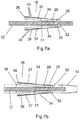
- FIG. 7 a is a side cross sectional view of the clamping assembly and the wedge member mounted to the shaft;
- FIG. 7 b is a side cross sectional view of the clamping assembly and the wedge member mounted to the shaft within the sleeve, with the clamp members extending outwardly through openings in the sleeve;
- FIG. 8 a is a perspective view a first of the clamping assemblies of the rock bolt of FIG. 1 ;
- FIG. 8 b is a perspective view of second of the clamping assembles of the rock bolt of FIG. 1 ;
- FIG. 8 c is a side view of the first of the clamping assemblies.
- FIG. 9 is a perspective view of an outer end of the rock bolt of FIG. 1 .
- a rock bolt 10 comprising generally a shaft 12 , a sleeve 14 and a plurality of clamping assemblies 16 .
- the shaft 12 comprises an elongate member having a thread on an outer surface thereof.
- the shaft 12 is of a length to be received within a hole drilled into a rock face to be stabilised by the rock bolt 10 .
- the shaft 12 is inserted into the drilled hole such that an inner end 18 of the rock bolt 10 is located adjacent the inner end of the hole and an outer end 19 of the rock bolt 10 protrudes outwardly from the hole.
- the sleeve 14 comprises an elongate tubular member having a generally circular transverse cross section.
- the shaft 12 is receivable into the sleeve 14 such that an annular space is defined between an inner surface of the sleeve 14 and an outer surface of the shaft 12 .
- the sleeve 14 is provided with a longitudinal slot 46 extending along the length thereof to allow for some compression of the sleeve when inserted into the drilled hole.
- the shaft 12 is contained within the sleeve 14 adjacent the inner end 18 of the rock bolt 10 and extends outwardly from the sleeve 14 adjacent the outer end 19 of the rock bolt 10 .
- the inner end 18 of the sleeve 14 includes a tapered end portion 20 to aid in inserting the rock bolt 10 into the drilled hole.
- the outer end 19 of the sleeve 14 includes an annular flange 22 such that a nut 24 received onto the outer end 19 of the shaft 12 may be tightened to move against the annular flange 22 .
- the rock bolt 10 includes also a plurality of wedge members 26 .
- Each of the wedge members 26 is associated with one of the clamping assemblies 16 .
- a first of the clamping assemblies 16 is located adjacent an inner end of the rock bolt 10 and a second of the clamping assemblies 16 is located between the inner and outer ends 18 and 19 of the rock bolt 10 .
- Each of the wedge members 26 comprises a tapered tubular member 28 .
- the tapered tubular members 28 are generally circular in transverse cross section and taper inwardly from a first end 50 to a second end 51 .
- the tubular members 28 each include a longitudinal bore 30 having an internal thread to receive the external thread of the shaft 12 .
- the wedge members 26 are oriented on the shaft 12 such that the first ends 50 thereof are directed towards the inner end 18 of the rock bolt 10 and the second ends 51 are directed towards the outer end 19 of the rock bolt 10 .
- Each of the clamping assemblies 16 in the embodiment shown comprises a ring 32 , a pair of arms 34 and a pair of corresponding clamp members 36 .
- the ring 32 includes an aperture for receiving the shaft 12 such that the ring 32 is located about the shaft 12 within the sleeve 14 .
- the arms 34 comprise elongate members having first ends secured to opposite sides of the ring 32 such that the arms 34 extend longitudinally adjacent opposed sides of the shaft 12 .
- the clamping assemblies 16 are located such that the arms 34 extend from the ring 32 towards the outer end 19 of the rock bolt 10 .
- Each of the arms 34 includes one of the clamp members 36 secured to a second end thereof, remote from the ring 32 .
- the wedge members 26 are to be located on the shaft 12 in use between the ring 32 and the clamp member 36 of each of the clamping assemblies 16 .
- the arms 34 of the clamping assemblies 16 are angled slightly outwardly such that the second ends of the arms 34 are located further from the shaft 12 than the first ends thereof.
- the sleeve 14 is provided with a plurality of openings 38 corresponding to each of the clamp members 36 .
- Each of the openings 38 includes a relatively wide first end portion 52 and a relatively narrow second end portion 53 .
- the first end portion 52 of the opening 38 is located on a side adjacent the inner end 18 of the rock bolt 10 .
- the first end portion 52 has a shape corresponding to the shape of the clamp member 36 such that the clamp member 36 may extend outwardly through the first end portion 52 of the opening 38 .
- the first end portion 52 of the opening 38 is rectangular.
- the second end portion 53 of the opening 38 has a shape corresponding to the shape of the arm 34 such that the arm 34 may extend outwardly through the second end portion 53 of the opening 38 .
- the second end portion 53 of the opening 38 in the embodiment shown comprises an elongate channel portion.
- the channel portions comprising the second end portions 53 of the openings 38 on one side of the sleeve 14 are aligned with the slot 46 such that the second end portions 53 of the openings 38 on that side of the sleeve 14 are formed by portions of the slot 46 .
- the arms 34 on which the clamp members 36 are mounted are flexible and resilient such that the clamp members 36 may be moved inwardly into the openings 38 such that the clamp members 36 are retained within the extents of the sleeve 14 .
- the resilience of the arms 34 however tends to move the clamp members 36 outwardly to engage with an inner surface of the drilled hole.
- each of the clamp members 36 comprises a part cylindrical member 37 .
- the part cylindrical members 37 are arcuate in transverse cross section such that the clamp members 36 extend around a portion of the outer surface of the shaft 12 .
- An outer surface of each of the part cylindrical members 37 includes a plurality of ribs 40 .
- the ribs 40 extends circumferentially around the part cylindrical member 37 .
- the ribs 40 are triangular in shape such that when the ribs 40 engage with an inner surface of the drilled hole, the ribs 40 provide a greater resistance to sliding movement along the inner surface in a direction outwardly relative to the hole than in a direction inwardly relative to the hole.
- Each of the wedge members 26 includes a pair of longitudinal grooves 42 on opposed sides thereof.
- the grooves 42 are provided for receiving the arms 34 when the arms 34 are compressed towards the wedge member 26 .
- Each of the clamp members 36 also includes a longitudinal groove 43 extending centrally from a first end to a second end thereof. The grooves 43 in the clamp members 36 are provided to receive the arms 34 , as can be seen in FIGS. 6 a and 6 b.
- the rock bolt 10 is inserted into a drilled hole with the clamp members 36 located adjacent the openings 38 and the wedge members 26 located between the clamp members 36 and the rings 32 of the clamping assemblies 16 . While sliding the rock bolt 10 into the hole, the clamp members 36 are pressed inwardly into the openings 38 , thereby flexing the arms 34 inwardly towards the shaft 12 . Once the rock bolt 10 is in the desired position, the shaft 12 is rotated by engaging a suitable tool onto the nut 24 .
- Rotation of the nut 24 causes the wedge members 26 to move relative to the shaft 12 in a direction towards the outer end 19 and thereby move between the pairs of clamp members 36 .
- Outer surfaces of the wedge members 26 engage against inner arcuate surfaces of the clamp members 36 , thereby moving the clamp members 36 outwardly through the openings 38 to engage inner surfaces of the drilled hole.
- Further tightening of the nut 24 increases the force with which the clamp members 36 engage the inner surface of the drilled hole, thereby securing the rock bolt 10 relative to the drilled hole.
- a pin 44 is preferably provided extending through the nut 24 into the shaft 12 to fix the nut 24 relative to the shaft 12 .
- the pin 44 is designed to fail on application of a predetermined force such that the clamping force between the rock bolt 10 and the drilled hole can be controlled to a desired level.
Landscapes
- Engineering & Computer Science (AREA)
- Mining & Mineral Resources (AREA)
- Structural Engineering (AREA)
- Life Sciences & Earth Sciences (AREA)
- General Life Sciences & Earth Sciences (AREA)
- Geochemistry & Mineralogy (AREA)
- Geology (AREA)
- Earth Drilling (AREA)
- Dowels (AREA)
- Drilling And Exploitation, And Mining Machines And Methods (AREA)
Abstract
Description
Claims (15)
Applications Claiming Priority (3)
| Application Number | Priority Date | Filing Date | Title |
|---|---|---|---|
| AU2017904679 | 2017-11-20 | ||
| AU2017904679A AU2017904679A0 (en) | 2017-11-20 | Rock Bolt | |
| PCT/AU2018/051215 WO2019095006A1 (en) | 2017-11-20 | 2018-11-13 | Rock bolt |
Publications (2)
| Publication Number | Publication Date |
|---|---|
| US20200277857A1 US20200277857A1 (en) | 2020-09-03 |
| US11220906B2 true US11220906B2 (en) | 2022-01-11 |
Family
ID=66538359
Family Applications (1)
| Application Number | Title | Priority Date | Filing Date |
|---|---|---|---|
| US16/765,471 Active US11220906B2 (en) | 2017-11-20 | 2018-11-13 | Rock bolt |
Country Status (8)
| Country | Link |
|---|---|
| US (1) | US11220906B2 (en) |
| AU (1) | AU2018368811B2 (en) |
| CA (1) | CA3082934A1 (en) |
| CL (1) | CL2020001337A1 (en) |
| MX (1) | MX2020005218A (en) |
| PE (1) | PE20210056A1 (en) |
| WO (1) | WO2019095006A1 (en) |
| ZA (1) | ZA202003632B (en) |
Cited By (1)
| Publication number | Priority date | Publication date | Assignee | Title |
|---|---|---|---|---|
| WO2024197348A1 (en) * | 2023-03-28 | 2024-10-03 | Sandvik Mining And Construction Australia (Production/Supply) Pty Ltd | A rock bolt |
Families Citing this family (1)
| Publication number | Priority date | Publication date | Assignee | Title |
|---|---|---|---|---|
| ES2985362T3 (en) | 2021-10-28 | 2024-11-05 | Sandvik Mining And Construction Australia Production/Supply Pty Ltd | Rock bolt |
Citations (3)
| Publication number | Priority date | Publication date | Assignee | Title |
|---|---|---|---|---|
| GB805797A (en) * | 1955-05-13 | 1958-12-10 | Forges Et Boulonneries Hermant | Improvements in and relating to an anchoring device e.g. for mine roofs and walls |
| US4453845A (en) * | 1983-01-19 | 1984-06-12 | Donan Jr David C | Base thrust anchor shell assembly |
| US20160215805A1 (en) * | 2013-08-08 | 2016-07-28 | Howa Corporation | Anchor bolt |
Family Cites Families (4)
| Publication number | Priority date | Publication date | Assignee | Title |
|---|---|---|---|---|
| US3469407A (en) * | 1967-12-22 | 1969-09-30 | Ohio Brass Co | Mine roof support |
| US3528253A (en) * | 1969-03-13 | 1970-09-15 | Ohio Brass Co | Mine roof support |
| WO2016116848A1 (en) * | 2015-01-20 | 2016-07-28 | Fci Holdings Delaware, Inc. | Point anchored friction bolt |
| AU2017207513A1 (en) * | 2016-01-12 | 2018-07-26 | Capell, Dale MR | A point anchoring device |
-
2018
- 2018-11-13 CA CA3082934A patent/CA3082934A1/en active Pending
- 2018-11-13 AU AU2018368811A patent/AU2018368811B2/en active Active
- 2018-11-13 PE PE2020000536A patent/PE20210056A1/en unknown
- 2018-11-13 US US16/765,471 patent/US11220906B2/en active Active
- 2018-11-13 WO PCT/AU2018/051215 patent/WO2019095006A1/en not_active Ceased
- 2018-11-13 MX MX2020005218A patent/MX2020005218A/en unknown
-
2020
- 2020-05-20 CL CL2020001337A patent/CL2020001337A1/en unknown
- 2020-06-17 ZA ZA2020/03632A patent/ZA202003632B/en unknown
Patent Citations (3)
| Publication number | Priority date | Publication date | Assignee | Title |
|---|---|---|---|---|
| GB805797A (en) * | 1955-05-13 | 1958-12-10 | Forges Et Boulonneries Hermant | Improvements in and relating to an anchoring device e.g. for mine roofs and walls |
| US4453845A (en) * | 1983-01-19 | 1984-06-12 | Donan Jr David C | Base thrust anchor shell assembly |
| US20160215805A1 (en) * | 2013-08-08 | 2016-07-28 | Howa Corporation | Anchor bolt |
Cited By (1)
| Publication number | Priority date | Publication date | Assignee | Title |
|---|---|---|---|---|
| WO2024197348A1 (en) * | 2023-03-28 | 2024-10-03 | Sandvik Mining And Construction Australia (Production/Supply) Pty Ltd | A rock bolt |
Also Published As
| Publication number | Publication date |
|---|---|
| MX2020005218A (en) | 2020-09-25 |
| CA3082934A1 (en) | 2019-05-23 |
| US20200277857A1 (en) | 2020-09-03 |
| PE20210056A1 (en) | 2021-01-11 |
| WO2019095006A1 (en) | 2019-05-23 |
| AU2018368811B2 (en) | 2023-11-30 |
| CL2020001337A1 (en) | 2020-08-21 |
| ZA202003632B (en) | 2021-05-26 |
| AU2018368811A1 (en) | 2020-06-25 |
Similar Documents
| Publication | Publication Date | Title |
|---|---|---|
| KR101570599B1 (en) | Electrical cable restrain device using a double wedge chuck | |
| KR100568606B1 (en) | Pipe coupling | |
| US5630817A (en) | Rod attachment device for rachidian orthopaedy | |
| KR102493549B1 (en) | Fastening element and assembly with such a fastening element and a receiving element | |
| US11220906B2 (en) | Rock bolt | |
| US9618051B2 (en) | Method and apparatus for mounting a machine element onto a shaft | |
| CA2669306A1 (en) | Fasteners and spacer rings therefor | |
| US20160215803A1 (en) | Fastening device having a tubular sleeve member for mounting on a tube or immobilizing two telescopically connected tubes | |
| US9568037B2 (en) | Machine element mounting assembly | |
| US5832158A (en) | Optical fiber inner tube connector | |
| CA2980619C (en) | Helical screw pile assemblies | |
| US7699357B2 (en) | Coupling for tubes | |
| US4372563A (en) | Packing support for mounting a well casing packing | |
| US20040115030A1 (en) | Detachable connection arrangement | |
| AU2024278469B2 (en) | Rock bolt | |
| SE539329C2 (en) | Clamp device for a fuel dispenser | |
| US20200258433A1 (en) | Assembly and method for rotatably securing an object to a fixture | |
| KR102911515B1 (en) | Extension anchor | |
| GB2137713A (en) | Rock anchor bolt assembly | |
| KR20190002995U (en) | Device for connecting rope | |
| US8602403B1 (en) | Cam actuated clamping device | |
| GB2137712A (en) | Rock bolt assembly | |
| EP1447023A1 (en) | Fitting arrangement for the attachment of an elongate member to a planar surface | |
| KR20150080691A (en) | Nut for Preventing Loosening | |
| CA2425825C (en) | Coupling assembly having a split-ring collar locking mechanism |
Legal Events
| Date | Code | Title | Description |
|---|---|---|---|
| FEPP | Fee payment procedure |
Free format text: ENTITY STATUS SET TO UNDISCOUNTED (ORIGINAL EVENT CODE: BIG.); ENTITY STATUS OF PATENT OWNER: SMALL ENTITY |
|
| FEPP | Fee payment procedure |
Free format text: ENTITY STATUS SET TO SMALL (ORIGINAL EVENT CODE: SMAL); ENTITY STATUS OF PATENT OWNER: SMALL ENTITY |
|
| STPP | Information on status: patent application and granting procedure in general |
Free format text: NON FINAL ACTION MAILED |
|
| STPP | Information on status: patent application and granting procedure in general |
Free format text: FINAL REJECTION MAILED |
|
| STPP | Information on status: patent application and granting procedure in general |
Free format text: DOCKETED NEW CASE - READY FOR EXAMINATION |
|
| STPP | Information on status: patent application and granting procedure in general |
Free format text: NON FINAL ACTION MAILED |
|
| STPP | Information on status: patent application and granting procedure in general |
Free format text: RESPONSE TO NON-FINAL OFFICE ACTION ENTERED AND FORWARDED TO EXAMINER |
|
| STPP | Information on status: patent application and granting procedure in general |
Free format text: NOTICE OF ALLOWANCE MAILED -- APPLICATION RECEIVED IN OFFICE OF PUBLICATIONS |
|
| STPP | Information on status: patent application and granting procedure in general |
Free format text: PUBLICATIONS -- ISSUE FEE PAYMENT VERIFIED |
|
| STCF | Information on status: patent grant |
Free format text: PATENTED CASE |
|
| AS | Assignment |
Owner name: AUMMS PTY LTD, AUSTRALIA Free format text: ASSIGNMENT OF ASSIGNORS INTEREST;ASSIGNOR:CATOI, PETER BRYCE;REEL/FRAME:068776/0424 Effective date: 20211104 |
|
| MAFP | Maintenance fee payment |
Free format text: PAYMENT OF MAINTENANCE FEE, 4TH YR, SMALL ENTITY (ORIGINAL EVENT CODE: M2551); ENTITY STATUS OF PATENT OWNER: SMALL ENTITY Year of fee payment: 4 |