US11220825B2 - Single course exterior cladding panel - Google Patents
Single course exterior cladding panel Download PDFInfo
- Publication number
- US11220825B2 US11220825B2 US16/365,324 US201916365324A US11220825B2 US 11220825 B2 US11220825 B2 US 11220825B2 US 201916365324 A US201916365324 A US 201916365324A US 11220825 B2 US11220825 B2 US 11220825B2
- Authority
- US
- United States
- Prior art keywords
- exterior cladding
- cladding panel
- series
- gaps
- exterior
- Prior art date
- Legal status (The legal status is an assumption and is not a legal conclusion. Google has not performed a legal analysis and makes no representation as to the accuracy of the status listed.)
- Active, expires
Links
Images


Classifications
-
- E—FIXED CONSTRUCTIONS
- E04—BUILDING
- E04F—FINISHING WORK ON BUILDINGS, e.g. STAIRS, FLOORS
- E04F13/00—Coverings or linings, e.g. for walls or ceilings
- E04F13/07—Coverings or linings, e.g. for walls or ceilings composed of covering or lining elements; Sub-structures therefor; Fastening means therefor
- E04F13/08—Coverings or linings, e.g. for walls or ceilings composed of covering or lining elements; Sub-structures therefor; Fastening means therefor composed of a plurality of similar covering or lining elements
- E04F13/0864—Coverings or linings, e.g. for walls or ceilings composed of covering or lining elements; Sub-structures therefor; Fastening means therefor composed of a plurality of similar covering or lining elements composed of superposed elements which overlap each other and of which the flat outer surface includes an acute angle with the surface to cover
-
- E—FIXED CONSTRUCTIONS
- E04—BUILDING
- E04D—ROOF COVERINGS; SKY-LIGHTS; GUTTERS; ROOF-WORKING TOOLS
- E04D1/00—Roof covering by making use of tiles, slates, shingles, or other small roofing elements
- E04D1/12—Roofing elements shaped as plain tiles or shingles, i.e. with flat outer surface
- E04D1/20—Roofing elements shaped as plain tiles or shingles, i.e. with flat outer surface of plastics; of asphalt; of fibrous materials
-
- E—FIXED CONSTRUCTIONS
- E04—BUILDING
- E04D—ROOF COVERINGS; SKY-LIGHTS; GUTTERS; ROOF-WORKING TOOLS
- E04D1/00—Roof covering by making use of tiles, slates, shingles, or other small roofing elements
- E04D1/26—Strip-shaped roofing elements simulating a repetitive pattern, e.g. appearing as a row of shingles
- E04D1/265—Strip-shaped roofing elements simulating a repetitive pattern, e.g. appearing as a row of shingles the roofing elements being rigid, e.g. made of metal, wood or concrete
-
- E—FIXED CONSTRUCTIONS
- E04—BUILDING
- E04D—ROOF COVERINGS; SKY-LIGHTS; GUTTERS; ROOF-WORKING TOOLS
- E04D1/00—Roof covering by making use of tiles, slates, shingles, or other small roofing elements
- E04D1/34—Fastenings for attaching roof-covering elements to the supporting elements
-
- E—FIXED CONSTRUCTIONS
- E04—BUILDING
- E04F—FINISHING WORK ON BUILDINGS, e.g. STAIRS, FLOORS
- E04F13/00—Coverings or linings, e.g. for walls or ceilings
- E04F13/07—Coverings or linings, e.g. for walls or ceilings composed of covering or lining elements; Sub-structures therefor; Fastening means therefor
- E04F13/08—Coverings or linings, e.g. for walls or ceilings composed of covering or lining elements; Sub-structures therefor; Fastening means therefor composed of a plurality of similar covering or lining elements
- E04F13/0889—Coverings or linings, e.g. for walls or ceilings composed of covering or lining elements; Sub-structures therefor; Fastening means therefor composed of a plurality of similar covering or lining elements characterised by the joints between neighbouring elements, e.g. with joint fillings or with tongue and groove connections
-
- E—FIXED CONSTRUCTIONS
- E04—BUILDING
- E04D—ROOF COVERINGS; SKY-LIGHTS; GUTTERS; ROOF-WORKING TOOLS
- E04D1/00—Roof covering by making use of tiles, slates, shingles, or other small roofing elements
- E04D1/34—Fastenings for attaching roof-covering elements to the supporting elements
- E04D2001/3444—Fastenings for attaching roof-covering elements to the supporting elements characterised by the roof covering or structure with integral or premounted fastening means
- E04D2001/3447—Fastenings for attaching roof-covering elements to the supporting elements characterised by the roof covering or structure with integral or premounted fastening means the fastening means being integral or premounted to the roof covering
-
- E—FIXED CONSTRUCTIONS
- E04—BUILDING
- E04D—ROOF COVERINGS; SKY-LIGHTS; GUTTERS; ROOF-WORKING TOOLS
- E04D1/00—Roof covering by making use of tiles, slates, shingles, or other small roofing elements
- E04D1/34—Fastenings for attaching roof-covering elements to the supporting elements
- E04D2001/3452—Fastenings for attaching roof-covering elements to the supporting elements characterised by the location of the fastening means
- E04D2001/3458—Fastenings for attaching roof-covering elements to the supporting elements characterised by the location of the fastening means on the upper or lower transverse edges of the roof covering elements
-
- E—FIXED CONSTRUCTIONS
- E04—BUILDING
- E04F—FINISHING WORK ON BUILDINGS, e.g. STAIRS, FLOORS
- E04F13/00—Coverings or linings, e.g. for walls or ceilings
- E04F13/07—Coverings or linings, e.g. for walls or ceilings composed of covering or lining elements; Sub-structures therefor; Fastening means therefor
- E04F13/08—Coverings or linings, e.g. for walls or ceilings composed of covering or lining elements; Sub-structures therefor; Fastening means therefor composed of a plurality of similar covering or lining elements
- E04F13/18—Coverings or linings, e.g. for walls or ceilings composed of covering or lining elements; Sub-structures therefor; Fastening means therefor composed of a plurality of similar covering or lining elements of organic plastics with or without reinforcements or filling materials or with an outer layer of organic plastics with or without reinforcements or filling materials; plastic tiles
Definitions
- the present disclosure relates generally to exterior cladding products and methods for installing and fabricating them.
- the present disclosure relates more particularly to exterior cladding panels, such as siding panels.
- Polymer-based siding such as polypropylene or vinyl siding
- Polypropylene or vinyl siding is among the most common exterior cladding systems used for residential construction in the United States.
- Polymer siding is typically manufactured into relatively large panels that include a series of adjacent surface courses that imitate the appearance of a wood clapboard surface.
- the panels are often installed with the siding courses in a horizontal orientation, and a given panel is usually engaged with the panels above and below it by way of interlocking clips or hooks included at the top and bottom of each panel.
- the result is an exterior cladding system that can be installed more easily, quickly, and more economically that many other alternatives.
- a relatively large, multi-course polymer siding panel may be oversized for some applications. For instance, installing a double or triple course siding panel in the gable ends of a house may result in excessive waste, or scrap, that is trimmed from the panel due to the angle of the roof. In these applications and others, a single-course siding panel may be used to reduce the amount of waste. Further, a single-course siding panel may provide more flexibility in varying shapes or colors within an overall siding system.
- an exterior cladding panel comprising:
- a locking leg extending from a rear face of the exterior cladding panel and positioned along a middle portion of the exterior cladding panel between the first end and the second end;
- each gap in the series of gaps extends lengthwise from the second end of the exterior cladding panel to the middle portion of the exterior cladding panel, and wherein each gap in the series of gaps comprises a first width that differs from a second width of at least one adjacent gap in the series of gaps.
- Another aspect of the disclosure is an exterior cladding system comprising:
- first exterior cladding panel is the exterior cladding panel as described herein;
- first exterior cladding panel is the exterior cladding panel as described herein, and wherein the locking leg of the second exterior cladding panel is sized to engage the series of locking clips of the first exterior cladding panel.
- Another aspect of the disclosure is an exterior cladding system comprising:
- first exterior cladding panel is the exterior cladding panel as described herein;
- the second exterior cladding panel comprises:
- locking leg of the second exterior cladding panel is sized to engage the second series of locking clips of the first exterior cladding panel.
- Another aspect of the disclosure is a wall of a structure comprising an exterior sheathing and the exterior cladding system described herein attached thereto, where the first exterior cladding panel is fastened to the exterior sheathing via a fastening strip disposed along an edge of the first end of the first exterior cladding panel, and where the locking leg of the second exterior cladding panel is engaged with the series of locking clips of the first exterior cladding panel.
- Another aspect of the disclosure is a wall of a structure comprising an exterior sheathing and the exterior cladding system described herein attached thereto, wherein the first exterior cladding panel is fastened to the exterior sheathing via a fastening strip disposed along an edge of the first end of the first exterior cladding panel, and wherein the locking leg of the second exterior cladding panel is engaged with the second series of locking clips of the first exterior cladding panel.
- Another aspect of the disclosure is a method for installing an exterior cladding system as described herein, the method comprising:
- Another aspect of the disclosure is a method for installing an exterior cladding system as described herein, the method comprising:
- forming the second series of locking clips comprises separating from the front face of the first exterior cladding panel, for a plurality of the protrusions extending from the front face of the exterior cladding panel, the portion of each protrusion facing the second end of the first exterior cladding panel;
- Another aspect of the disclosure is a method for forming an exterior cladding panel as described herein, the method comprising:
- injection molding the exterior cladding panel to include:
- FIG. 1 is a schematic front view of an exterior cladding panel according to one embodiment of the disclosure.
- FIG. 2 is a schematic front view of an exterior cladding panel according to another embodiment of the disclosure.
- FIG. 3 is a schematic front view of an exterior cladding panel according to another embodiment of the disclosure.
- FIG. 4 is a schematic rear view of an exterior cladding panel according to another embodiment of the disclosure.
- FIG. 5 is a schematic perspective view of a rear face of an exterior cladding panel according to another embodiment of the disclosure.
- FIG. 6 is another schematic perspective view of a rear face of an exterior cladding panel according to another embodiment of the disclosure.
- FIG. 7 is a schematic perspective view of a front face of an exterior cladding panel according to another embodiment of the disclosure.
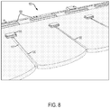
- FIG. 8 is another schematic perspective view of a front face of an exterior cladding panel according to another embodiment of the disclosure.
- FIG. 9 is a schematic right side view of an exterior cladding panel according to another embodiment of the disclosure.
- FIG. 10 is a schematic left side view of an exterior cladding panel according to another embodiment of the disclosure.
- FIG. 11 is a schematic top view of an exterior cladding panel according to another embodiment of the disclosure.
- FIG. 12 is a schematic bottom view of an exterior cladding panel according to another embodiment of the disclosure.
- FIG. 13 is a schematic perspective view of a partially installed exterior cladding system according to another embodiment of the disclosure.
- FIG. 14 is a block diagram of a method for installing an exterior cladding system according to another embodiment of the disclosure.
- FIG. 15 is a block diagram of a method for installing an exterior cladding system according to another embodiment of the disclosure.
- FIG. 16 is a block diagram of a method for forming an exterior cladding system according to another embodiment of the disclosure.
- the present inventors have noted disadvantages of some conventional exterior cladding systems, such as polymer-based siding panels.
- polymer siding is often manufactured in relatively large panels including a plurality of siding courses of similar height.
- the present inventors have noted that a single-course siding panel, due to its relatively smaller size, will repeat more frequently when it is utilized in a given siding system. In some cases, this repetition may result in undesirable visible patterns that can disrupt the simulated wood surface that the siding system is intended to provide.
- a single-course siding panel may be formed as series of simulated shingles separated by a series of gaps.
- each single-course siding panel that is installed will be separated from adjacent panels to its left or right by an installation gap.
- These installation gaps may be subject to change in width due to the thermal expansion of the siding panels post-installation. Such changes in width may be easily noticeable if the surrounding gaps have an otherwise uniform appearance.
- an exterior cladding panel may be formed, such as a polymer siding panel, for instance, that randomizes the gap widths between shingles such that a pattern is not as readily discerned. Further, the irregular gap widths within each panel may serve to mask the changes in gap widths that may occur in between exterior cladding panels due to heating and cooling of the panels. Accordingly, one aspect of the disclosure is an exterior cladding panel, such as a polymer siding panel, including a series of simulated shingles with a series of gaps separating adjacent shingles. Each gap in the series of gaps may include a first width that differs from a second width of at least one adjacent gap in the series of gaps.
- the exterior cladding panel as described herein may introduce a random or irregular-looking pattern to the gaps between simulated shingles, which may provide for a more visually-appealing appearance to some.
- the example exterior cladding panels discussed herein may more accurately recreate a genuine wood shingle appearance, which may include natural variation.
- FIGS. 1-3 show three examples of a schematic front view of an exterior cladding panel 100 according to certain embodiments of the disclosure.
- the exterior cladding panel 100 includes a first end 101 , arranged in FIGS. 1-3 to be the top end of the exterior cladding panel 100 .
- the exterior cladding panel 100 includes a series of locking clips 103 extending from a front face 104 of the exterior cladding panel 100 and positioned along the first end 101 of the exterior cladding panel 100 .
- the exterior cladding panel 100 also includes a series of simulated shingles 105 positioned in a single course between the first end 101 and the second end 102 .
- the series of shingles 105 may take a number of shapes.
- the series of simulated shingles 105 include a rounded appearance, while the series of simulated shingles 105 a in FIG. 2 have a more pointed, cove-like arrangement.
- the series of simulated shingles 105 b in FIG. 3 include a hexagonal shape at the second end 102 of the exterior cladding panel 100 .
- the shape of the shingles may constitute the only difference between the exterior cladding panels 100 , as all other features are the same, or substantially the same. Accordingly, although many of the embodiments shown in the remaining Figures and discussed herein may generally depict the rounded shingles as shown in FIG. 1 , it will be understood that the alternative shapes shown in FIGS. 2-3 , or any other shapes, may also be utilized.
- the exterior cladding panel 100 may include a fastening strip 122 disposed along an edge 121 of the first end 101 , which can be seen most clearly in the examples shown in FIGS. 1-6 .
- the fastening strip 122 may be used to fasten the exterior cladding panel 100 to the exterior sheathing of a wall of a structure, as further discussed below.
- the exterior cladding panel 100 further includes a locking leg 107 extending from a rear face 108 of the exterior cladding panel 100 .
- the locking leg 107 can be seen in FIG. 4 , which shows a schematic rear view of the exterior cladding panel 100 .
- the locking leg 107 is positioned along a middle portion 109 of the exterior cladding panel 100 , between the first end 101 and the second end 102 , and may be used to engage the exterior cladding panel 100 with a locking clip of an adjacent panel.
- Other locations for the locking leg 107 are also possible.
- the series of simulated shingles 105 may include a series of gaps 106 separating adjacent shingles in the series of simulated shingles 105 .
- Each gap in the series of gaps 106 may extend lengthwise from the second end 102 of the exterior cladding panel 100 to the middle portion 109 of the exterior cladding panel 100 .
- each gap in the series of gaps 106 may include a first width 110 a that differs from a second width 110 b of at least one adjacent gap in the series of gaps 106 .
- the series of locking clips 103 may correspond to the series of gaps 106 such that each locking clip in the series of locking clips 103 is aligned with a respective gap in the series of gaps 106 .
- Other arrangements for the series of locking clips 103 with respect to the series of gaps 106 are also possible.
- varying the gap widths between the shingles in the series of simulated shingles 105 may be desirable in order to create an irregular pattern that is relatively less noticeable to an onlooker.
- the irregular pattern of gap widths can serve to obscure changes in width that may occur at the gap between installed panels, due to thermal expansion. Such changes in the gap width in between installed panels might otherwise be conspicuous if every other gap width is the same, or if a more regular pattern is used.
- the first width 110 a of a given gap may differ from the second width 110 b of a first adjacent gap, and may also differ from a third width 110 c of a second adjacent gap.
- FIG. 3 shows each of the gaps in the series of gaps 106 individually labeled with one of three widths, 110 a , 110 b , or 110 c .
- the second gap in the series from the left has a width 110 a , which differs from the first adjacent gap to the left (i.e., the first gap in the series), which has a width 110 b , and also differs from the second adjacent gap to the right (i.e., the third gap in the series), which has a width of 110 c.
- the width of a given gap in the series of gaps 106 may differ from both adjacent gaps, however both adjacent gaps may have the same width.
- FIG. 3 shows a width 110 c .
- Both the adjacent second and adjacent fourth gaps in the series have a width 110 a that differs from the width 110 c , however they are the same as each other, Still further, considering the fourth gap in the series of gaps 106 as shown in FIG.
- the first width 110 a may differ from a second width 110 b of a first adjacent gap (i.e., the third gap in the series, to the left), but be the same as a third width 110 a of a second adjacent gap (i.e., the fifth gap in the series, to the right).
- a given gap width may be repeated within the series of gaps 106 .
- the series of gaps 106 may include at least three gaps having mutually different widths, as shown by the widths 110 a , 110 b , and 110 c the example of FIG. 3 .
- This in addition to the sequencing of the differing widths, may introduce a level of apparent randomness that makes the detection of patterns in the gaps less likely. Further conventions may also be followed relating to the arrangement of the gaps widths as well. For instance, no more than two consecutive gaps in the series of gaps 106 may have the same width. Other examples are also possible.
- the series of locking clips 103 may be a first series of locking clips 103
- the exterior cladding panel 100 may further include a second series of locking clips 113 extending from the front face 104 of the exterior cladding panel 100 .
- the second series of locking clips 113 may be positioned in the middle portion 109 of the exterior cladding panel 100 , between the first series of locking clips 103 and the series of gaps 106 , as shown in FIGS. 1-3 .
- the second series of locking clips 113 may correspond to the series of gaps 106 such that each locking clip in the second series of locking clips 113 is aligned with a respective gap in the series of gaps 106 .
- FIG. 5 a schematic perspective view of the rear face 108 of an example exterior cladding panel 100 is shown.
- the locking leg 107 can be seen in more detail, which may extend approximately parallel to the rear face 108 of the exterior cladding panel 100 . Further, the locking leg 107 may include a first edge 111 , shown as an upper edge in FIG. 5 , and a second edge 112 , shown as a lower edge in FIG. 5 .
- the locking leg 107 may be attached to the rear face 108 of the exterior cladding panel 100 along the second edge 112 , which is shown in more detail in FIG. 6 .
- FIG. 6 illustrates another schematic perspective view of the rear face 108 of the exterior cladding panel 100 , and shows an example where the locking leg 107 is attached to the rear face 108 of the exterior cladding panel 100 by a plurality of interspaced ribs 114 extending from the second edge 112 of the locking leg 107 .
- the plurality of interspaced ribs 114 may be desirable over other alternatives, such as a continuous connection.
- attaching the locking leg 107 to the rear face 108 may result in a sink mark, or depression, on the front face 104 of the exterior cladding panel 100 , opposite the connection. This may cause a visual defect, as even a minor sink mark may be noticeable if it runs across the entire horizontal length of the exterior cladding panel 100 , which includes otherwise vertically oriented shingles and gaps.
- the ribs 113 may be interspaced far enough from each other such that the injection molding process does not produce a noticeable sink mark on the front face 104 of the exterior cladding panel 100 .
- the plurality of interspaced ribs 113 must be numerous enough and/or have a sufficient enough cross section to adequately secure the exterior cladding panel 100 to the locking clip(s) an adjacent exterior cladding panel, we well as withstand any additional design loading, such as wind loads.
- the locking leg 107 may be attached to each shingle in the series of simulated shingles 105 by at least four interspaced ribs from the plurality of interspaced ribs 113 . For instance, as shown in FIG. 6 , the locking leg 107 is attached to the first shingle (and each other shingle in the series of simulated shingles 105 ) by five interspaced ribs from the plurality of interspaced ribs 113 .
- each locking clip in the second series of locking clips 113 may be formed from a protrusion 115 extending from the front face 104 of the exterior cladding panel 100 . Further, a portion 116 of each protrusion 115 facing the second end 102 of the exterior cladding panel 100 may be separable from the front face 104 of the exterior cladding panel 100 to form each locking clip in the second series of locking clips 113 .
- FIG. 7 a schematic perspective view of the front face 104 of an example exterior cladding panel 100 is shown.
- each locking clip in the second series of locking clips 113 may be formed from a protrusion 115 extending from the front face 104 of the exterior cladding panel 100 .
- a portion 116 of each protrusion 115 facing the second end 102 of the exterior cladding panel 100 may be separable from the front face 104 of the exterior cladding panel 100 to form each locking clip in the second series of locking clips 113 .
- FIG. 7 a schematic perspective view of the front face 104
- each protrusion 115 depicts an initial stage following the formation of the exterior cladding panel 100 where, for each protrusion 115 , the portion 116 facing the second end 102 of the exterior cladding panel 100 is not yet separated from the front face 104 of the exterior cladding panel 100 .
- the back side of each protrusion 115 can be seen in FIG. 5 , where no portion of the protrusion is yet separated from the front face 104 .
- FIG. 8 illustrates another schematic perspective view of the front face 104 of the exterior cladding panel 100 , where the portion 116 of each protrusion 115 facing the second end 102 of the exterior cladding panel 100 has been separated from the front face 104 .
- the portion 116 facing the second end 102 generally represents the bottom of each protrusion 115 in the example shown.
- respective side portions of each protrusion 115 may be separated from the front face 104 as well, resulting in a second series of locking clips 113 with a shape that is relatively similar to that of the first series of locking clips 113 .
- each protrusion 115 may be accomplished by cutting them away from each protrusion 115 , with a utility knife, for example.
- the exterior cladding panel 100 may be formed such that the portion 116 of each protrusion 115 to be cut away includes a relatively thin layer of plastic material, or flashing.
- each protrusion 115 in the second series of locking clips 113 can remain connected to the front face 104 of the exterior cladding panel 100 on all sides if the second series of locking clips 113 are not going to be used for a particular application. In these applications, a throughway for moisture to pass through the exterior cladding panel 100 is not created unnecessarily.
- FIG. 8 also provides a closer view of a few gaps in the series of gaps 106 .
- each gap in the series of gaps 106 may include a depth 120 measured normal to the front face 104 of the exterior cladding panel 100 . Further, the depth 120 of each gap in the series of gaps 106 may increase from the middle portion 109 of the exterior cladding panel 100 toward the second end 102 of the exterior cladding panel 100 .
- the exterior cladding panel 100 may include a recessed portion 117 that is positioned within each gap, which may provide additional structural integrity for the exterior cladding panel 100 . Accordingly, the depth of each gap may be measured from the front face 104 to the recessed portion 117 of the exterior cladding panel 100 . The depth may be relatively shallow at the top end of each gap, near the second series of locking clips 113 . The depth 120 may then increase along the length of each gap, as shown in FIG. 8 .
- This variation in the depth along each gap may provide variation in the shadow line created by each gap, which may be desirable in some implementations.
- the gradient or slope of the recessed portion 117 within each gap may be the same, and thus the depth of each gap with vary in the same manner.
- the slope of the recessed portion 117 may differ between different gaps, which, in combination with other examples discussed herein, may result in gaps having both a differing width and a differing depth within the series of gaps 106 .
- FIGS. 9 and 10 a schematic right side view and a schematic left side view of an example exterior cladding panel 100 are shown, respectively.
- Some of the features discussed above can be seen, including the first series of locking clips 103 and the second series of locking clips 113 .
- the separable portion 116 has not yet been separated from the front face of the exterior cladding panel 100 , as discussed above with respect to FIGS. 7-8 , Further, the locking leg 107 is shown, extending approximately parallel to the rear face 108 of the exterior cladding panel 100 .
- FIGS. 11 and 12 depict a schematic top view and a schematic bottom view, respectively, of an example exterior cladding panel 100 . Due to the relatively thin profile of the exterior cladding panel 100 , relatively few features of the exterior cladding panel 100 are visible in the top and bottom views shown in FIGS. 11 and 12 , although the series of simulated shingles 105 and the series of gaps 106 can be seen.
- the exterior cladding system 300 need not be installed or partially installed for all components of the system to be present.
- the exterior cladding system 300 may include a first exterior cladding panel 100 a and a second exterior cladding panel 100 b , both of which may be substantially similar or the same as the exterior cladding panel 100 shown in FIGS. 1-12 and discussed in examples herein.
- the locking leg 107 of the second exterior cladding panel 100 b may be sized to engage the series of locking clips 103 of the first exterior cladding panel 100 a.
- the second end 102 of the exterior cladding panel 100 b when installed, will overhang the entire top portion 102 and some of the middle portion 109 of the exterior cladding panel 100 a .
- This overhang will cover, for example, the unused second series of locking clips 113 , and position the bottommost edge of the second exterior cladding panel 100 b at the top of the series of gap 106 in the first exterior cladding panel 100 a , as can be seen in the partially assembled view in FIG. 13 .
- the exterior cladding system 300 may include a first panel 100 b , where the first panel 100 b is substantially similar to or the same as the exterior cladding panel 100 shown in FIGS. 1-12 and discussed above.
- the exterior cladding panel 100 b may include the second series of locking clips 113 .
- the system 300 may include a second exterior cladding panel 800 , such as the exterior cladding panel 800 shown in FIG. 13 , which includes double course of simulated shingles.
- Exterior cladding panel 800 may include a first end 801 and a second end 802 .
- the exterior cladding panel 800 may include a locking leg extending along a bottom edge of the second end 802 of the second exterior cladding panel 800 .
- the locking leg of the second exterior cladding panel 800 may be sized to engage the second series of locking clips 113 of the first exterior cladding panel 100 b.
- this example arrangement of the exterior cladding system 300 illustrates a situation where the second series of locking clips 113 is used. Because the locking leg of the second exterior cladding panel 800 is situated at the bottom edge of the exterior cladding panel 800 , there is no remaining panel to overhang the first exterior cladding panel 100 b . Thus, if the locking leg of the second exterior cladding panel 800 may be sized to engage the second series of locking clips 113 , such that the bottommost edge of the second exterior cladding panel 800 is positioned at the top of the series of gap 106 in the first exterior cladding panel 100 b , as can be seen in the partially assembled view in FIG. 13 .
- FIG. 13 shows a wall 400 of a structure including an exterior sheathing 401 , and the exterior cladding system 300 as discussed in some of the examples above partially attached thereto.
- the exterior cladding panel 100 a may be fastened to the exterior sheathing 401 via a fastening strip disposed along an edge of the first end of the exterior cladding panel 100 a , such as the fastening strip 122 shown with respect to the exterior cladding panel 100 in FIG. 1 .
- the locking leg of the second exterior cladding panel 100 b which may be substantially similar to or the same as the locking leg 107 shown in FIGS. 4-6 , may be engaged with a series of locking clips of the first exterior cladding panel 100 a , which may be substantially similar to or the same as the series of locking clips 103 shown in FIG. 7 .
- the wall 400 may include the exterior sheathing 401 and the exterior cladding system 300 as discussed in some other examples above attached thereto.
- the exterior cladding panel 100 b may be fastened to the exterior sheathing 401 via a fastening strip disposed along an edge of the first end of the exterior cladding panel 100 b , such as the fastening strip 122 shown with respect to the exterior cladding panel 100 in FIG. 1 .
- the locking leg of the second exterior cladding panel 800 which may be situated at the bottom edge of the exterior cladding panel 800 , may be engaged with a second series of locking clips of the first exterior cladding panel 100 b , which may be substantially similar to or the same as the second series of locking clips 113 shown in FIG. 8 .
- FIG. 14 is a block diagram of a method 500 for installing an exterior cladding system, such as the exterior cladding system 300 according to some examples discussed herein, onto a wall of a structure according to an embodiment of the disclosure.
- an exterior cladding system such as the exterior cladding system 300 according to some examples discussed herein
- the method 500 includes fastening the first exterior cladding panel 100 a to the exterior sheathing 401 via a fastening strip disposed along an edge of the first end of the first exterior cladding panel 100 a .
- the fastening strip may be substantially similar to or the same as fastening strip 122 shown with respect to the exterior cladding panel 100 in FIG. 1
- the first exterior cladding panel 100 a may be fastened to the exterior sheathing 401 via nails driven through slots in the fastening strip 122 . Staples and other fasteners may be utilized as well.
- the method 500 includes engaging the locking leg, such as a locking leg 107 as discussed above, of the second exterior cladding panel 100 b with the series of locking clips, such as the series of locking clips 103 , of the first exterior cladding panel 100 a.
- the method 500 includes fastening the second exterior cladding panel 100 b to the exterior sheathing 401 via a fastening strip disposed along the edge of the first end of the second exterior cladding panel 100 b .
- the fastening strip may be the substantially similar to or the same as fastening strip 122 disposed along the edge 121 of the first end 102 of the exterior cladding panel 100 shown in FIG. 1 .
- FIG. 15 is a block diagram of a method 600 for installing an exterior cladding system, such as the exterior cladding system 300 according to some examples discussed herein, onto a wall of a structure according to another embodiment of the disclosure.
- an exterior cladding system such as the exterior cladding system 300 according to some examples discussed herein
- the method 600 includes fastening the first exterior cladding panel 100 b to the exterior sheathing 401 via a fastening strip disposed along an edge of the first end of the first exterior cladding panel 100 b .
- the fastening strip may the fastening strip 122 shown with respect to the exterior cladding panel 100 in FIG. 1
- the first exterior cladding panel 100 b may be fastened to the exterior sheathing 401 via nails driven through slots in the fastening strip 122 . Staples and other fasteners may be utilized as well.
- the method 600 includes forming the second series of locking clips.
- the second series of locking clips may be substantially similar to or the same as the second series of locking clips 113 discussed in the examples above.
- forming the second series of locking clips 113 may include separating from the front face of the first exterior cladding panel 100 b , for a plurality of the protrusions 115 extending from the front face of the exterior cladding panel 100 b , the portion 116 of each protrusion 115 facing the second end of the first exterior cladding panel 100 b .
- the portion 116 may be cut away using a utility knife or other similar tool.
- forming the second series of locking clips 113 may include separating other portions of each protrusion as well, such as their respective side portions, as shown in FIG. 8 .
- the method 600 includes engaging the locking leg of a second exterior cladding panel 800 , which may be situated at the bottom edge of the exterior cladding panel 800 , with the second series of locking clips 113 of the first exterior cladding panel 100 b.
- the method 600 includes fastening the second exterior cladding panel 100 b to the exterior sheathing 401 via a fastening strip disposed along the edge of the first end of the second exterior cladding panel 800 .
- the fastening strip may be the substantially similar to or the same the other fastening strips discussed in the examples above.
- FIG. 16 is a block diagram of a method 700 for forming an exterior cladding panel, such as the exterior cladding panel 100 discussed herein, according to another embodiment of the disclosure.
- the method 700 includes injection molding the exterior cladding panel 100 to include a first end 101 and a series of locking clips 103 extending from a front face 104 of the exterior cladding panel 100 and positioned along the first end 101 of the exterior cladding panel 100 , as shown in FIGS. 1-12 and discussed above. Further, the method 700 may include injection molding the exterior cladding panel 100 to include a second end 102 , and a locking leg 107 extending from a rear face 108 of the exterior cladding panel 100 and positioned along a middle portion 109 of the exterior cladding panel 100 between the first end 101 and the second end 102 .
- the method 700 may also include injection molding the exterior cladding panel 100 to include a series of simulated shingles 105 positioned in a single course between the first end 101 and the second end 102 .
- the series of simulated shingles 105 may include a series of gaps 106 separating adjacent shingles in the series of simulated shingles 105 .
- Each gap in the series of gaps 106 may be injection molded to extend lengthwise from the second end 102 of the exterior cladding panel 100 to the middle portion 109 of the exterior cladding panel 100 .
- each gap in the series of gaps may be injection molded to include a first width 110 a that differs from a second width 110 b of at least one adjacent gap in the series of gaps 106 .
- the at least one adjacent gap in the series of gaps 106 is a first adjacent gap
- injection molding the exterior cladding panel 100 to include the series of simulated shingles 105 may include injection molding the series of gaps 106 such that the first width 110 a also differs from a third width 110 c of a second adjacent gap in the series of gaps 106 , as shown in the example of FIG. 3 .
- the exterior cladding panel 100 may be injection molded to include at least three gaps having mutually different widths.
- the at least one adjacent gap in the series of gaps 106 is a first adjacent gap
- injection molding the exterior cladding panel 100 to include the series of simulated shingles 105 may include injection molding the series of gaps 106 such that the first width 110 a is the same as a third width 110 a of a second adjacent gap in the series of gaps 106 , as shown in the example of FIG. 3 and discussed above.
- the series of locking clips 103 may be injection molded to correspond to the series of gaps 106 such that each locking clip in the series of locking clips 103 is aligned with a respective gap in the series of gaps 106 .
- the series of gaps 106 may be injection molded such that each gap in the series of gaps 106 includes a depth 120 measured normal to the front face 104 of the exterior cladding panel 100 , and such that the depth 120 of each gap in the series of gaps 106 increases from the middle portion 109 of the exterior cladding panel 100 toward the second end 102 of the exterior cladding panel 100 , as shown in FIG. 8 and discussed above.
- injection molding the exterior cladding panel 100 to include the locking leg 107 may include injection molding the locking leg 107 to extend approximately parallel to the rear face 108 of the exterior cladding panel 100 , such that the locking leg 107 comprises a first edge 111 and a second edge 112 , and such that the locking leg 107 is attached to the rear face 108 of the exterior cladding panel 100 by a plurality of interspaced ribs 113 extending from the second edge 112 of the locking leg 107 .
- injection molding the exterior cladding panel 100 to include the locking leg 107 may include injection molding the attachment of the locking leg 107 to the rear face 108 of the exterior cladding panel 100 such that the locking leg 107 is attached to each shingle in the series of simulated shingles 105 by at least four interspaced ribs as discussed above and as shown in FIG. 6 .
- the series of locking clips 103 may be a first series of locking clips 103
- injection molding the exterior cladding panel 100 may further include injection molding the exterior cladding panel 100 to include a second series of locking clips 113 extending from the front face 104 of the exterior cladding panel 100 and positioned in the middle portion 109 of the exterior cladding panel 100 , between the series of the first locking clips 103 and the series of gaps 106 .
- injection molding the exterior cladding panel 100 to include the second series of locking clips 113 may include injection molding each locking clip in the second series of locking clips 113 as a protrusion 115 extending from the front face 104 of the exterior cladding panel 100 , such that a portion 116 of each protrusion 115 facing the second end 102 of the exterior cladding panel 100 is separable from the front face 104 of the exterior cladding panel 100 to form each locking clip in the second series of locking clips 113 .
- injection molding the exterior cladding panel 100 to include the second series of locking clips 113 may include injection molding the second series of locking clips 13 to correspond to the series of gaps 106 such that each locking clip in the second series of locking clips 113 is aligned with a respective gap in the series of gaps 106 .
- Exterior cladding construction can be used in the installation and formation of the exterior cladding panels as described herein.
- the embodiments and implementations described herein, in conjunction with the Figures have generally discussed an exterior cladding system and an exterior cladding panel that is oriented with horizontally arranged courses, with reference to course and adjacent exterior cladding panels positioned in series both above and below.
- the exterior cladding panels, systems, and methods described herein are not limited to a horizontal arrangement.
- the exterior cladding panels and exterior cladding systems described above may be installed vertically, or at any angle between zero and ninety degrees.
- Exterior cladding panels may be installed in an orientation that matches the underlying surface to which the exterior cladding panels are applied, for instance, as well as for a variety of visual, structural, and/or thermal effects and performance.
Landscapes
- Engineering & Computer Science (AREA)
- Architecture (AREA)
- Civil Engineering (AREA)
- Structural Engineering (AREA)
- Mechanical Engineering (AREA)
- Finishing Walls (AREA)
Abstract
Description
-
- a first end;
- a second end; and
- a locking leg extending along an edge of the second end of the second exterior cladding panel; and
-
- a first end;
- a series of locking clips extending from a front face of the exterior cladding panel and positioned along the first end of the exterior cladding panel;
- a second end;
- a locking leg extending from a rear face of the exterior cladding panel and positioned along a middle portion of the exterior cladding panel between the first end and the second end; and
- a series of simulated shingles positioned in a single course between the first end and the second end, wherein the series of simulated shingles comprises a series of gaps separating adjacent shingles in the series of simulated shingles, wherein each gap in the series of gaps extends lengthwise from the second end of the exterior cladding panel to the middle portion of the exterior cladding panel, and wherein each gap in the series of gaps comprises a first width that differs from a second width of at least one adjacent gap in the series of gaps.
Claims (22)
Priority Applications (1)
| Application Number | Priority Date | Filing Date | Title |
|---|---|---|---|
| US16/365,324 US11220825B2 (en) | 2018-03-30 | 2019-03-26 | Single course exterior cladding panel |
Applications Claiming Priority (2)
| Application Number | Priority Date | Filing Date | Title |
|---|---|---|---|
| US201862650337P | 2018-03-30 | 2018-03-30 | |
| US16/365,324 US11220825B2 (en) | 2018-03-30 | 2019-03-26 | Single course exterior cladding panel |
Publications (2)
| Publication Number | Publication Date |
|---|---|
| US20190301173A1 US20190301173A1 (en) | 2019-10-03 |
| US11220825B2 true US11220825B2 (en) | 2022-01-11 |
Family
ID=68054927
Family Applications (1)
| Application Number | Title | Priority Date | Filing Date |
|---|---|---|---|
| US16/365,324 Active 2039-06-09 US11220825B2 (en) | 2018-03-30 | 2019-03-26 | Single course exterior cladding panel |
Country Status (2)
| Country | Link |
|---|---|
| US (1) | US11220825B2 (en) |
| CA (1) | CA3038435A1 (en) |
Cited By (2)
| Publication number | Priority date | Publication date | Assignee | Title |
|---|---|---|---|---|
| US20220381040A1 (en) * | 2021-05-25 | 2022-12-01 | Certainteed Llc | Building surface panel with reinforced nail slot, and method of manufacture |
| US20240392578A1 (en) * | 2023-05-22 | 2024-11-28 | Louisiana-Pacific Corporation | Tapered engineered wood shake with shiplap edge |
Families Citing this family (3)
| Publication number | Priority date | Publication date | Assignee | Title |
|---|---|---|---|---|
| US11035128B2 (en) | 2018-03-30 | 2021-06-15 | Certainteed Llc | Exterior cladding panels and methods for installing them |
| CA3139154A1 (en) | 2020-11-13 | 2022-05-13 | Certainteed Llc | Flat siding panel and panel siding system |
| GB2636942A (en) * | 2023-05-30 | 2025-07-02 | Russell Building Products Ltd | A triple roof tile |
Citations (18)
| Publication number | Priority date | Publication date | Assignee | Title |
|---|---|---|---|---|
| US5537792A (en) * | 1995-03-23 | 1996-07-23 | Nailite International | Decorative wall covering |
| US20020095901A1 (en) * | 2001-01-16 | 2002-07-25 | Tecta Inc. | Metal roofing shingle |
| US6635218B2 (en) | 1998-05-22 | 2003-10-21 | Daniel W. King | Continuous production of plastic siding panels with separate shingle appearance |
| US6715250B2 (en) * | 1999-09-08 | 2004-04-06 | Alcoa Inc. | Plastic siding panel |
| US6725618B2 (en) * | 2000-06-12 | 2004-04-27 | Gregory P. Albracht | Siding and overhang attachment system |
| USD507837S1 (en) * | 2004-06-10 | 2005-07-26 | Tapco International Corporation | Shake siding panel |
| US6955019B2 (en) * | 2002-05-10 | 2005-10-18 | Nailite International | Decorative wall covering with upward movement panel interlock system |
| US6976342B1 (en) | 1999-11-29 | 2005-12-20 | Peter Kowalevich | Fully interlocking synthetic, simulated shake siding |
| US20060026908A1 (en) * | 2004-08-05 | 2006-02-09 | Gregori Werner K H | Simulated wood shingles with multiple alignment features |
| US20060130419A1 (en) * | 2003-02-18 | 2006-06-22 | Modco Technology (Canada) Ltd. | Roofing panel system |
| US20070107356A1 (en) * | 2005-11-01 | 2007-05-17 | Certainteed Corporation | Staggered look shake siding panel with improved locking mechanism |
| US20080083187A1 (en) * | 2006-10-06 | 2008-04-10 | The Tapco International Corporation | Split tile for attachment to a building structure |
| US7698864B2 (en) * | 2005-07-14 | 2010-04-20 | Atlantis Plastics, Inc. | Bonded siding panels |
| US7735286B2 (en) * | 2007-02-05 | 2010-06-15 | Exteria Building Products | Roof and wall covering with improved corner construction |
| US20100205886A1 (en) * | 2006-09-05 | 2010-08-19 | Jenkin Timber Limited | Fixing System for Cladding |
| US20110061323A1 (en) * | 2009-07-29 | 2011-03-17 | Exterior Building Products, LLC | Simulated Masonry Wall Panel with Improved Seam Integration |
| US20140272273A1 (en) | 2013-03-15 | 2014-09-18 | Certainteed Corporation | Variegated building product and method |
| US20150167315A1 (en) | 2013-12-18 | 2015-06-18 | Certainteed Corporation | Panel siding product |
-
2019
- 2019-03-26 US US16/365,324 patent/US11220825B2/en active Active
- 2019-03-29 CA CA3038435A patent/CA3038435A1/en active Pending
Patent Citations (20)
| Publication number | Priority date | Publication date | Assignee | Title |
|---|---|---|---|---|
| US5537792A (en) * | 1995-03-23 | 1996-07-23 | Nailite International | Decorative wall covering |
| US7008213B2 (en) * | 1998-05-22 | 2006-03-07 | Tapco International Corporation | Continuous production of plastic siding panels with separate shingle appearance |
| US6635218B2 (en) | 1998-05-22 | 2003-10-21 | Daniel W. King | Continuous production of plastic siding panels with separate shingle appearance |
| US6715250B2 (en) * | 1999-09-08 | 2004-04-06 | Alcoa Inc. | Plastic siding panel |
| US6976342B1 (en) | 1999-11-29 | 2005-12-20 | Peter Kowalevich | Fully interlocking synthetic, simulated shake siding |
| US6725618B2 (en) * | 2000-06-12 | 2004-04-27 | Gregory P. Albracht | Siding and overhang attachment system |
| US20020095901A1 (en) * | 2001-01-16 | 2002-07-25 | Tecta Inc. | Metal roofing shingle |
| US6955019B2 (en) * | 2002-05-10 | 2005-10-18 | Nailite International | Decorative wall covering with upward movement panel interlock system |
| US20060130419A1 (en) * | 2003-02-18 | 2006-06-22 | Modco Technology (Canada) Ltd. | Roofing panel system |
| USD507837S1 (en) * | 2004-06-10 | 2005-07-26 | Tapco International Corporation | Shake siding panel |
| US20060026908A1 (en) * | 2004-08-05 | 2006-02-09 | Gregori Werner K H | Simulated wood shingles with multiple alignment features |
| US7698864B2 (en) * | 2005-07-14 | 2010-04-20 | Atlantis Plastics, Inc. | Bonded siding panels |
| US20070107356A1 (en) * | 2005-11-01 | 2007-05-17 | Certainteed Corporation | Staggered look shake siding panel with improved locking mechanism |
| US20100205886A1 (en) * | 2006-09-05 | 2010-08-19 | Jenkin Timber Limited | Fixing System for Cladding |
| US8381475B2 (en) * | 2006-09-05 | 2013-02-26 | Jenkin Timber Limited | Fixing system for cladding |
| US20080083187A1 (en) * | 2006-10-06 | 2008-04-10 | The Tapco International Corporation | Split tile for attachment to a building structure |
| US7735286B2 (en) * | 2007-02-05 | 2010-06-15 | Exteria Building Products | Roof and wall covering with improved corner construction |
| US20110061323A1 (en) * | 2009-07-29 | 2011-03-17 | Exterior Building Products, LLC | Simulated Masonry Wall Panel with Improved Seam Integration |
| US20140272273A1 (en) | 2013-03-15 | 2014-09-18 | Certainteed Corporation | Variegated building product and method |
| US20150167315A1 (en) | 2013-12-18 | 2015-06-18 | Certainteed Corporation | Panel siding product |
Non-Patent Citations (5)
| Title |
|---|
| CertainTeed Corporation, "Accents" brochure, 2014. |
| CertainTeed Corporation, "Cedar Impressions(R)," 2010. |
| CertainTeed Corporation, "Installation Instructions, Cedar Impressions(R) Half-Round Shingles," May 2006. |
| CertainTeed Corporation, "Specification Sheet," Cedar Impressions(R), Nov. 2016. |
| CertainTeed Corporation, "The Authentic Beauty of New CertainTeed® Cedar Impressions® Single 7-inch Perfection Shingle Siding Is Much More Than Skin Deep," Apr. 19, 2016. |
Cited By (3)
| Publication number | Priority date | Publication date | Assignee | Title |
|---|---|---|---|---|
| US20220381040A1 (en) * | 2021-05-25 | 2022-12-01 | Certainteed Llc | Building surface panel with reinforced nail slot, and method of manufacture |
| US12031334B2 (en) * | 2021-05-25 | 2024-07-09 | Certainteed Llc | Building surface panel with reinforced nail slot, and method of manufacture |
| US20240392578A1 (en) * | 2023-05-22 | 2024-11-28 | Louisiana-Pacific Corporation | Tapered engineered wood shake with shiplap edge |
Also Published As
| Publication number | Publication date |
|---|---|
| US20190301173A1 (en) | 2019-10-03 |
| CA3038435A1 (en) | 2019-09-30 |
Similar Documents
| Publication | Publication Date | Title |
|---|---|---|
| US11220825B2 (en) | Single course exterior cladding panel | |
| US5537792A (en) | Decorative wall covering | |
| US9890537B2 (en) | Siding or roofing panel system | |
| CA2302598C (en) | Injection molded exterior siding panel with positioning relief and method of installation | |
| US20060026908A1 (en) | Simulated wood shingles with multiple alignment features | |
| US6224701B1 (en) | Molded plastic siding panel | |
| US7654050B2 (en) | Corner trim piece for siding | |
| US6955019B2 (en) | Decorative wall covering with upward movement panel interlock system | |
| US11560723B2 (en) | Interchangeable board and batten | |
| US11732483B2 (en) | Exterior cladding panels and methods for installing them | |
| US7587871B2 (en) | Simulated hand laid brick and mortar wall covering | |
| US20060130419A1 (en) | Roofing panel system | |
| PL232033B1 (en) | Roof and wall covering of the improved corner design | |
| US20040237428A1 (en) | Manually separable ridge vent | |
| US10731357B2 (en) | Ventilated thin brick panel system | |
| US7901757B2 (en) | Molded plastic panel | |
| US20080083187A1 (en) | Split tile for attachment to a building structure | |
| US11466464B2 (en) | Clip attachment for panel system | |
| EP0306477B1 (en) | Interlocking panels | |
| JP2000199312A (en) | Ventilation ridge tile batten |
Legal Events
| Date | Code | Title | Description |
|---|---|---|---|
| FEPP | Fee payment procedure |
Free format text: ENTITY STATUS SET TO UNDISCOUNTED (ORIGINAL EVENT CODE: BIG.); ENTITY STATUS OF PATENT OWNER: LARGE ENTITY |
|
| STPP | Information on status: patent application and granting procedure in general |
Free format text: DOCKETED NEW CASE - READY FOR EXAMINATION |
|
| STPP | Information on status: patent application and granting procedure in general |
Free format text: RESPONSE TO NON-FINAL OFFICE ACTION ENTERED AND FORWARDED TO EXAMINER |
|
| STPP | Information on status: patent application and granting procedure in general |
Free format text: NON FINAL ACTION MAILED |
|
| STPP | Information on status: patent application and granting procedure in general |
Free format text: RESPONSE TO NON-FINAL OFFICE ACTION ENTERED AND FORWARDED TO EXAMINER |
|
| STPP | Information on status: patent application and granting procedure in general |
Free format text: NOTICE OF ALLOWANCE MAILED -- APPLICATION RECEIVED IN OFFICE OF PUBLICATIONS |
|
| AS | Assignment |
Owner name: CERTAINTEED CORPORATION, PENNSYLVANIA Free format text: NUNC PRO TUNC ASSIGNMENT;ASSIGNORS:STEFFES, STEPHEN W.;KIRN, BRIAN W.;SIGNING DATES FROM 20211206 TO 20211207;REEL/FRAME:058326/0313 Owner name: CERTAINTEED LLC, PENNSYLVANIA Free format text: CONVERSION;ASSIGNOR:CERTAINTEED CORPORATION;REEL/FRAME:058358/0316 Effective date: 20191022 |
|
| STPP | Information on status: patent application and granting procedure in general |
Free format text: PUBLICATIONS -- ISSUE FEE PAYMENT VERIFIED |
|
| STCF | Information on status: patent grant |
Free format text: PATENTED CASE |
|
| AS | Assignment |
Owner name: CERTAINTEED LLC, PENNSYLVANIA Free format text: CONVERSION, MERGER, CONVERSION;ASSIGNOR:CERTAINTEED LLC;REEL/FRAME:060613/0636 Effective date: 20191023 |
|
| MAFP | Maintenance fee payment |
Free format text: PAYMENT OF MAINTENANCE FEE, 4TH YEAR, LARGE ENTITY (ORIGINAL EVENT CODE: M1551); ENTITY STATUS OF PATENT OWNER: LARGE ENTITY Year of fee payment: 4 |