US11220417B2 - Hybrid clamp force control for lift truck attachment - Google Patents
Hybrid clamp force control for lift truck attachment Download PDFInfo
- Publication number
- US11220417B2 US11220417B2 US16/420,000 US201916420000A US11220417B2 US 11220417 B2 US11220417 B2 US 11220417B2 US 201916420000 A US201916420000 A US 201916420000A US 11220417 B2 US11220417 B2 US 11220417B2
- Authority
- US
- United States
- Prior art keywords
- hydraulic
- control circuit
- fluid
- hydraulic actuator
- cylinder
- Prior art date
- Legal status (The legal status is an assumption and is not a legal conclusion. Google has not performed a legal analysis and makes no representation as to the accuracy of the status listed.)
- Active
Links
Images


Classifications
-
- B—PERFORMING OPERATIONS; TRANSPORTING
- B66—HOISTING; LIFTING; HAULING
- B66F—HOISTING, LIFTING, HAULING OR PUSHING, NOT OTHERWISE PROVIDED FOR, e.g. DEVICES WHICH APPLY A LIFTING OR PUSHING FORCE DIRECTLY TO THE SURFACE OF A LOAD
- B66F9/00—Devices for lifting or lowering bulky or heavy goods for loading or unloading purposes
- B66F9/06—Devices for lifting or lowering bulky or heavy goods for loading or unloading purposes movable, with their loads, on wheels or the like, e.g. fork-lift trucks
- B66F9/075—Constructional features or details
- B66F9/20—Means for actuating or controlling masts, platforms, or forks
- B66F9/22—Hydraulic devices or systems
-
- B—PERFORMING OPERATIONS; TRANSPORTING
- B25—HAND TOOLS; PORTABLE POWER-DRIVEN TOOLS; MANIPULATORS
- B25B—TOOLS OR BENCH DEVICES NOT OTHERWISE PROVIDED FOR, FOR FASTENING, CONNECTING, DISENGAGING, OR HOLDING
- B25B5/00—Clamps
- B25B5/06—Arrangements for positively actuating jaws
- B25B5/061—Arrangements for positively actuating jaws with fluid drive
- B25B5/062—Arrangements for positively actuating jaws with fluid drive with clamping means pivoting around an axis parallel to the pressing direction
-
- B—PERFORMING OPERATIONS; TRANSPORTING
- B25—HAND TOOLS; PORTABLE POWER-DRIVEN TOOLS; MANIPULATORS
- B25J—MANIPULATORS; CHAMBERS PROVIDED WITH MANIPULATION DEVICES
- B25J13/00—Controls for manipulators
- B25J13/08—Controls for manipulators by means of sensing devices, e.g. viewing or touching devices
- B25J13/081—Touching devices, e.g. pressure-sensitive
- B25J13/082—Grasping-force detectors
-
- B—PERFORMING OPERATIONS; TRANSPORTING
- B66—HOISTING; LIFTING; HAULING
- B66F—HOISTING, LIFTING, HAULING OR PUSHING, NOT OTHERWISE PROVIDED FOR, e.g. DEVICES WHICH APPLY A LIFTING OR PUSHING FORCE DIRECTLY TO THE SURFACE OF A LOAD
- B66F9/00—Devices for lifting or lowering bulky or heavy goods for loading or unloading purposes
- B66F9/06—Devices for lifting or lowering bulky or heavy goods for loading or unloading purposes movable, with their loads, on wheels or the like, e.g. fork-lift trucks
- B66F9/075—Constructional features or details
- B66F9/12—Platforms; Forks; Other load supporting or gripping members
- B66F9/18—Load gripping or retaining means
- B66F9/183—Coplanar side clamps
-
- B—PERFORMING OPERATIONS; TRANSPORTING
- B23—MACHINE TOOLS; METAL-WORKING NOT OTHERWISE PROVIDED FOR
- B23Q—DETAILS, COMPONENTS, OR ACCESSORIES FOR MACHINE TOOLS, e.g. ARRANGEMENTS FOR COPYING OR CONTROLLING; MACHINE TOOLS IN GENERAL CHARACTERISED BY THE CONSTRUCTION OF PARTICULAR DETAILS OR COMPONENTS; COMBINATIONS OR ASSOCIATIONS OF METAL-WORKING MACHINES, NOT DIRECTED TO A PARTICULAR RESULT
- B23Q1/00—Members which are comprised in the general build-up of a form of machine, particularly relatively large fixed members
- B23Q1/25—Movable or adjustable work or tool supports
- B23Q1/26—Movable or adjustable work or tool supports characterised by constructional features relating to the co-operation of relatively movable members; Means for preventing relative movement of such members
- B23Q1/28—Means for securing sliding members in any desired position
-
- B—PERFORMING OPERATIONS; TRANSPORTING
- B25—HAND TOOLS; PORTABLE POWER-DRIVEN TOOLS; MANIPULATORS
- B25B—TOOLS OR BENCH DEVICES NOT OTHERWISE PROVIDED FOR, FOR FASTENING, CONNECTING, DISENGAGING, OR HOLDING
- B25B5/00—Clamps
- B25B5/16—Details, e.g. jaws, jaw attachments
-
- B—PERFORMING OPERATIONS; TRANSPORTING
- B66—HOISTING; LIFTING; HAULING
- B66F—HOISTING, LIFTING, HAULING OR PUSHING, NOT OTHERWISE PROVIDED FOR, e.g. DEVICES WHICH APPLY A LIFTING OR PUSHING FORCE DIRECTLY TO THE SURFACE OF A LOAD
- B66F9/00—Devices for lifting or lowering bulky or heavy goods for loading or unloading purposes
- B66F9/06—Devices for lifting or lowering bulky or heavy goods for loading or unloading purposes movable, with their loads, on wheels or the like, e.g. fork-lift trucks
- B66F9/075—Constructional features or details
- B66F9/12—Platforms; Forks; Other load supporting or gripping members
- B66F9/18—Load gripping or retaining means
- B66F9/184—Roll clamps
Definitions
- the subject matter of this application generally relates to improved systems and methods for operating a lift truck attachment used to grasp and move loads.
- lift trucks are used to pick up and move loads from one location to another. Because lift trucks must typically transport many different types of loads, lift trucks usually include a mast that supports a vertically extensible carriage, which can be selectively interconnected to any one of a variety of different hydraulically operated lift truck attachments, each intended to securely engage and move a specific type of load.
- a particular lift truck attachment may include a pair of horizontally spaced forks intended to slide into respective slots of a pallet that supports a load to be moved.
- Another lift truck attachment may include a pair of opposed, vertically-oriented clamps intended to firmly grasp the lateral sides of a load so that the lift truck can raise the load and move it.
- Hydraulic control systems for clamp attachments therefore typically include some type of load-weight sensing mechanism along with a control system that regulates gripping force by gradually increasing gripping fluid pressure automatically from a relatively low initial pressure to a pressure just sufficient to allow the load to be raised, without slipping.
- Hydraulic control systems for clamp attachments will also typically coordinate the movement of the clamps towards the load, so that one clamp does not prematurely strike and damage the load, cause the load to skid towards the other clamp, etc.
- control systems typically utilize flow dividers, such as spool and gear flow dividers to split hydraulic fluid evenly to each of the clamps.
- Spool-type flow dividers split flow through pressure-compensated fixed orifices, which ensures near-equal flow through the orifices, even when inlet and/or outlet pressures fluctuate.
- spool flow dividers must balance accuracy with the ability to tolerate oil contamination without failure.
- Spool flows dividers are designed to accurately divide flow only within a narrow range of flow rates; because spool dividers use fixed orifices, equal division of flow may not occur when used below the rated flow for a specific divider, and if flow exceeds the rating of the valve, the high pressure drop across the valve causes poor performance and fluid heating.
- Gear flow dividers though able to perform over a wider range of operating flow rates than spool dividers, are generally very expensive and the hydraulic circuit must be properly designed to prevent intensification if one clamp is restricted from moving.
- FIG. 1 shows an exemplary hydraulic control circuit that uses fluid provided from a lift truck to operate respective hydraulic cylinders, which may each drive a respective clamp on a lift truck attachment.
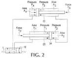
- FIG. 2 shows the pressures and forces applied by hydraulic cylinders controlled by the circuit of FIG. 1 .
- FIG. 3 shows the exemplary hydraulic control circuit of FIG. 1 connected to a pair of hydraulic cylinders used to operate a pivot arm clamp.
- FIG. 4 shows a first exemplary synchronizing plunger that may be used in the hydraulic control circuit of FIG. 1 .
- FIG. 5A shows the synchronizing plunger of FIG. 3 in a mid-stroke position and pressurized from the rod side.
- FIG. 5B shows the synchronizing plunger of FIG. 3 in an end-of-stroke position and pressurized from the rod side.
- FIG. 5C shows the synchronizing plunger of FIG. 3 in a mid-stroke position and pressurized from the head side.
- FIG. 6 shows a second exemplary synchronizing plunger that may be used in the hydraulic control circuit of FIG. 1 .
- FIG. 7A shows the synchronizing plunger of FIG. 5 in a mid-stroke position and pressurized from the rod side.
- FIG. 7B shows the synchronizing plunger of FIG. 5 in an end-of-stroke position and pressurized from the rod side.
- FIG. 7C shows the synchronizing plunger of FIG. 5 in a mid-stroke position and pressurized from the head side.
- FIG. 7D shows the synchronizing plunger of FIG. 5 in an end-of-stroke position and pressurized from the head side.
- FIG. 8 shows an alternate control circuit 84 used to control respective hydraulically operated motors of a lift truck attachment.
- FIG. 9 shows an alternate control circuit 90 capable of coordinating the movement of hydraulic actuators while such actuators are either linked or not linked.
- hydraulic actuators on industrial equipment such as a lift truck or a lift truck attachment
- first configuration where the actuators are hydraulically linked
- second configuration where the actuators are not hydraulically linked
- hydraulic actuator refers to any device that has first and second fluid line connections, where a difference in fluid pressure across the connections is used to impart motion to the actuator.
- hydraulic actuators include, but are not limited to, hydraulic cylinders and hydraulically operated motors.
- the term “input port” refers to a pair of connections that, in operation of the control circuit, are capable of receiving pressurized fluid from an external source such as a lift truck and thereby pressurizing at least one output port of the control circuit, as later defined, while simultaneously returning unpressurized fluid back to the external source, e.g. lift truck.
- the terms “hydraulically linked,” “hydraulically linking,” and similar terms, when referring to two or more hydraulic actuators means that the fluid pressure at the discharge side of a first actuator is fluidly communicated to the input side of a second actuator, i.e. the hydraulically linked actuators are connected in series.
- not hydraulically linked means that the fluid pressure at the discharge side of either actuator is not connected to the input side of the other actuator.
- coordinated when used with respect to two or more hydraulic actuators, hydraulic cylinders, clamps, etc. means that the movement of such elements must occur together, while the term “not coordinated” means that the movement of one hydraulic actuator, hydraulic cylinder, clamp, etc. may occur independently of the other such elements.
- a paper roll clamp or a carton clamp will use hydraulic actuators not only to cause clamp arms to apply a force to a load so as to securely lift it, but also will position the clamp arms by either moving together to initially contact the load or moving apart to release the load.
- efficiency is improved if clamp arms are positioned at a high speed and low force, but low speed and high force is desired to avoid damaging the load when clamping it.
- some material handling equipment allows a grasped load to be rotated about an axis, thus requiring that clamps rotate to first align with a load, then rotate after a load is grasped.
- the novel systems and methods disclosed by the present application beneficially allow material handling vehicles, attachments etc. to hydraulically link the actuators during one mode of operation and disengage that hydraulic linkage during another mode of operation.
- a clamp attachment as described in the preceding paragraph, when coordinating the movement of two clamps toward or away from a load, simultaneously operating hydraulically cylinders or other actuators that move the clamps can be performed at a high-speed of operation, but that high-speed operation risks damaging the load after contact. This risk can be reduced by operating the hydraulic cylinders in series, but this would make the clamps less efficient at grasping the load by reducing the effective cylinder area used to generate clamp force.
- one embodiment of the disclosed system and methods hydraulically links cylinders during clamp positioning, i.e. when the clamps are moved outwardly such as to release a load, and/or when the clamps are moved inwardly toward the load so as to clamp it, until a time proximate when the clamps grasp the load, at which point the hydraulic cylinders are no longer linked such that the effective cylinder area is increased and clamp force control can be adjusted more efficiently.
- Other alternative embodiments of the disclosed systems and methods may hydraulically link the cylinders that move the clamps during an opening movement, and bypass the hydraulic linkage during a closing movement, for example.
- FIG. 1 shows an exemplary system 10 that includes a hydraulic control circuit 12 that operates hydraulic actuators 20 and 22 using pressurized fluid provided from, e.g. a lift truck or other industrial equipment having a pump or motor 14 and reservoir 16 .
- the hydraulic circuit 12 includes an input port having connections 19 a and 19 b thus permitting fluid connection to a lift truck or other industrial equipment so that fluid may be provided under pressure to one of the input connections 19 a , 19 b while depressurized fluid is returned to the lift truck via the other one of the input connections 19 a , 19 b .
- each of the connections 19 a and 19 b will alternately receive pressurized fluid and expel unpressurized fluid depending on which direction fluid is flowing through the circuit, e.g. whether the cylinders 20 , 22 are retracting or extending.
- the hydraulic circuit 12 preferably includes a first output port having connections 21 a , 21 b and a second output port having connections 23 a , 23 b .
- Each output port is selectively connectable to a respective hydraulic actuator, such as one of the cylinders 20 , 22 so that the actuators may be driven in a desired direction or other mode by selecting which connection of a respective output port to pressurize, while allowing fluid thereby expelled from the actuator to return to the circuit 12 from the other connection of the output port.
- connection 21 a is connected to the rod side of cylinder 20 and connection 21 b is connected to the head side of cylinder 20 as shown in FIG.
- connection 21 a if output connection 21 a is pressurized, fluid will flow into the rod-side of cylinder 20 which will then retract, causing fluid to be expelled from the head side of the cylinder 20 back into the circuit 12 through connection 21 b .
- output connection 21 b if output connection 21 b is pressurized, fluid will flow into the head side of cylinder 20 , which will expand and cause fluid to flow from the cylinder 20 back into the circuit 21 through connection 21 a.
- the hydraulic circuit 12 also preferably includes a selector, such as the sequence valve 28 of FIG. 1 , which determines whether or not the first output port 21 a , 21 b and the second output port 23 a , 23 b are operated in series, as explained in detail later in this specification.
- a selector such as the sequence valve 28 of FIG. 1 , which determines whether or not the first output port 21 a , 21 b and the second output port 23 a , 23 b are operated in series, as explained in detail later in this specification.
- the selector is a device or arrangement of devices configured in the hydraulic circuit 12 capable of alternatingly selecting whether or not the control circuit 12 interconnects the output ports such that fluid returned from one hydraulic actuator into the control circuit 12 is used to pressurize a connection of the port of another hydraulic actuator.
- the selector may alternatingly select whether connected hydraulic actuators are connected in series to an input port of the control circuit 12 , or whether connected hydraulic actuators are connected in parallel to an input port of the control circuit 12 . In other embodiments, the selector may select whether connected hydraulic actuators are connected in series to an input port of the control circuit 12 , or whether one hydraulic actuator is pressurized by the input port of the control circuit and exhausts fluid towards the input port while another hydraulic actuator is not pressurized by the input port and does not exhaust fluid towards the input port. Regardless of such variations, by selectively determining whether or not hydraulic actuators are linked in series, the control circuit 12 may be used in a variety of different hydraulically operated devices such as lift truck attachments to operate more efficiently.
- FIG. 1 shows a circuit 12 used to provide pressurized fluid to a pair of hydraulic cylinders 20 and 22 typical of a carton clamp or roll clamp attachment where retraction of the rods of the cylinders 20 and 22 brings the clamps together and extension of the rods of the cylinders 20 and 22 moves the clamps apart.
- Opening and closing movement of the cylinders 20 and 22 is manually selectable by direction control valve 18 , which when moved to the left from the neutral position shown in FIG. 1 will close the clamps towards the load by providing pressurized fluid to port 19 a of the control circuit 12 and returning unpressurized fluid to the tank 16 through port 19 b of the control circuit 12 , and when moved to the right from the neutral position shown in FIG.
- the pump or motor 14 , the reservoir or tank 16 , and the directional control valve 18 are each located on a lift truck that supplies pressurized fluid to a lift truck attachment via fluid lines extending over the mast of the lift truck to the attachment, which in turn would typically include the hydraulic cylinders 20 and 22 along with their associated clamps and the control circuit 12 used to operate the attachment.
- pressurized fluid will flow through pilot operated check valve 24 , which is used to maintain the load-gripping force (pressure) in the primary cylinder 20 , through output port connection 21 a and into the rod side of the primary cylinder 20 which will accordingly contract to move it's associated clamp inwardly, e.g. toward a load. Fluid will then be expelled from the head side of the primary cylinder 20 through output port connection 21 b of the control circuit 12 .
- fluid sequence valve 28 (whose operation as the previously-described selector will be explained later) prevents the fluid from returning to the tank 16 through port 19 b , the fluid expelled from the primary cylinder 20 will flow through pilot-operated check valve 26 , through output port connection 23 a of the control circuit 12 , and into the rod-side of secondary cylinder 22 , which will also contract to move its associated clamp inwardly, e.g. toward a load. Fluid is then expelled from the head side of secondary cylinder 22 and into output port connection 23 b to return to the tank 16 via port 19 b of the control circuit 12 .
- sequence valve 28 is maintained in the closed position as shown in FIG. 1 , cylinders 20 and 22 are connected in series, and movement of the clamps is coordinated while the clamps are moving inwardly toward a load prior to contacting the load, without using a flow divider, providing an improvement in clamp speed.
- sequence valve 28 operates to alternate a mode of operation of the primary and secondary cylinders 20 , 22 , during a closing movement, between a first mode of operation where the primary and secondary cylinders 20 , 22 are hydraulically linked over a first range of motion of the primary cylinder, and a second mode of operation where the primary and secondary cylinders 20 , 22 are not hydraulically linked over a second range of motion of the primary cylinder.
- sequence valve 28 is operated by a rise in pressure as a load is clamped
- other means may be employed for actuating the sequence valve, or otherwise switching the cylinders 20 and 22 from a first, hydraulically linked mode to a second, non-hydraulically linked mode, such as using a valve actuated when a clamp arm or cylinder expands or retracts beyond a specific location, or using a sensor-operated solenoid valve, etc.
- the primary and secondary cylinders may switch from being hydraulically linked as clamps reach a location proximate to a load, but not yet contacting it.
- the hydraulic control circuit 12 operates to alternate a mode of operation of the primary and secondary cylinders 20 , 22 , between a clamp-opening movement where the cylinders 20 and 22 are hydraulically linked, and a clamp closing movement where the cylinders 20 and 22 are not hydraulically linked over at least a portion of the closing movement.
- alternate embodiments may include hydraulic control circuits that have cylinders 20 and 22 linked during the entirely of the opening movements and not linked during the entirety of the closing movement.
- FIG. 2 generally illustrates how pressures and forces are transmitted through the primary and secondary cylinders 20 and 22 , and their associated clamps due to the operation of the hydraulic control circuit 12 as previously described.
- the rod-side area A 1 of the primary cylinder 20 is designed to yield the required load-gripping force at an expected input oil pressure.
- the required cylinder force is 4,180 lbs at an input pressure of 2000 psi
- the required rod-side area A 1 is 2.09 in 2 .
- This area can be achieved by using a rod diameter of 1.10 inches (28 mm) and a bore of 1.97 inches (50 mm).
- the rod-side area A 3 of the secondary cylinder 22 is preferably designed to have equal, or near-equal, area to the head-side area A 2 of the primary cylinder. This matched area allows for equal movement of each cylinder, i.e. one inch of movement of the rod of the primary cylinder 20 will result in one inch of movement of the rod of the primary cylinder 22 .
- the rod side Area A 1 of the primary cylinder is 2.09 in 2 and head area A 2 is 3.04 in 2 .
- the secondary cylinder 22 thus preferably has an equal rod said area A 3 of 3.04 in 2 .
- Such a cylinder might be constructed with a rod diameter of 1.26 inches (32 mm) and a bore diameter of 2.34 inches (59.4 mm).
- FIG. 3 shows an alternate embodiment where the control circuit 12 of FIG. 1 may be used to control hydraulic actuators or cylinders 27 , 29 typically found in a pivot arm clamp where the extension of the cylinders 27 , 29 provides a gripping force on a load and the retraction of cylinders 27 , 29 releases a load.
- the control circuit 12 of FIG. 1 may be used to control hydraulic actuators or cylinders 27 , 29 typically found in a pivot arm clamp where the extension of the cylinders 27 , 29 provides a gripping force on a load and the retraction of cylinders 27 , 29 releases a load.
- the cylinders 27 , 29 are connected to the control circuit so that, during clamp closing, pressurized fluid is provided to the head side of primary cylinder 27 , and is expelled from the rod-side of cylinder 27 , and when hydraulically linked, fluid expelled from the rod-side of cylinder 27 is provided to the head side of cylinder 29 , with the rod side of cylinder 29 connected to connection 23 b , and hence 19 b .
- the head side area of cylinder 29 is preferably equal to the rod side area of cylinder 27 to ensure that, when hydraulically linked, equal movement of the cylinders 27 , 29 occurs.
- the secondary cylinder 22 in some embodiments may remain stationary while the primary cylinder 20 applies additional clamping force. Due to this asynchronous behavior of the primary and secondary cylinders, continued use of the hydraulic circuit 10 may cause one of the cylinders 20 , 22 to reach their end-of-stroke before the other cylinder does, which can inhibit the ability of the system to either adequately clamp the load or retract the clamps to their fully retracted position.
- the hydraulic circuit 10 may preferably include an optional resynchronizing valve 25 that allows fluid to bypass the hydraulic linkage when one cylinder has reached its end-of stroke before the other cylinder.
- the resynchronizing valve 25 allows oil to flow directly from the pressurized line 30 to the rod-side of the secondary cylinder 22 whenever the pressure difference between the rod-side of the primary cylinder 20 and the rod-side of the secondary cylinder 22 exceeds a threshold amount set by the spring setting of the resynchronizing valve 25 .
- the spring setting of the resynchronizing valve 25 should be sufficiently high to both ensure that the sequence valve 28 opens before the resynchronizing valve 25 opens, and to otherwise prevent the valve 25 from opening when the cylinders 20 , 22 are hydraulically linked while being positioned toward a load prior to clamping it.
- the pressure setting of the spring of valve 25 should be set to a value higher than the highest anticipated pressure drop across the primary cylinder 20 during positioning, which in turn is related to the maximum intended positioning speed of the valve circuit 10 .
- the spring setting of the resynchronizing valve 25 may preferably be set to about 150 psi lower than the system pressure setting.
- the resynchronizing valve 25 configured to resynchronize cylinders 20 and 22 by moving the rods of both cylinders to the fully retracted position, may instead be configured to resynchronize cylinders 20 and 22 by moving the rods of both cylinders to the fully extended position, by e.g. connecting the input of the resynchronizing valve 25 to line 32 instead of line 30 , and connecting the output of the resynchronizing valve 25 to the head side of primary cylinder 20 instead of the rod side of secondary cylinder 22 .
- one or both of the primary and secondary cylinders 20 , 22 may be configured to selectively operate as a valve that allows resynchronization by allowing oil to flow from the rod-side to the head side of the cylinder, or vice versa, when the cylinder has reached an end-of-stroke position.
- either or both the primary or secondary cylinders 20 or 22 may comprise a synchronizing cylinder 40 having a cylinder shell 42 that encloses at least a portion of a sliding cylinder rod 44 , which is fixed in a threaded bore 48 of a sliding piston 46 .
- the piston 46 preferably includes a wear band 50 and a piston seal 52 to provide for sealed, sliding movement of the piston within the cylinder shell 42 .
- the cylinder rod 44 may define a conduit for pressurized oil to flow back and forth between the rod-side area of the cylinder 40 (i.e. area A 1 or A 3 of FIG. 2 ) to the interior of the piston 46 .
- the cylinder rod 44 may include a conduit 53 comprising a passage with a first portion that extends axially inwards from the end of the rod 44 embedded in the piston 46 to a second portion that includes a plurality of radial passages to the periphery of the cylinder rod 44 .
- the piston-side of the conduit 53 may be selectively sealed by a check ball 58 mounted on a spring 56 that pushes the check ball 58 toward the first, axial portion of the conduit 53 .
- the end of the spring 56 opposite the check ball 58 is in turn secured around a flange of a sliding plunger 54 .
- the flange of the plunger 54 fits within a seat of a retainer 59 such that oil within the interior of the piston 46 is sealed from entering the head side area of the cylinder 40 (i.e. Area A 2 or A 4 of FIG. 2 ), or flowing in the opposite direction, when the flange of the plunger 54 rests in the seat of the retainer 59 .
- the plunger 54 contacts cylinder head 57 which compresses the spring 56 between the flange of the plunger 54 and the unseated check ball 58 , such that the plunger 54 comes off of the seat of the retainer 59 and oil is allowed to flow from rod-side area of the cylinder 40 , to the interior of the piston 46 , and out to the head side area of the cylinder 40 , and ultimately to the other cylinder 20 or 22 (or the tank 16 ) via porting 55 , to allow resynchronization. As shown in FIG.
- FIG. 6 shows an alternate synchronizing cylinder 60 capable of resynchronizing at either the fully retracted or fully extended end-of-stroke position of the rod of the cylinder 60 .
- cylinder 60 may comprise a cylinder shell 62 within which a piston 66 is slidably and sealably secured via seal 74 and one or more wear bands 72 .
- Rigidly mounted within a first bore 65 of the piston 66 by e.g. a heat shrink connection, is the end of a cylinder rod 64 that slides with the piston 66 .
- the piston 66 also defines a second bore 67 that houses a spool 68 that generally matches the shape of the second bore 67 , such that a gap is defined between the outer surface of the spool 68 and the inner surface of the second bore 67 .
- Both the second bore 67 and the spool 68 have a central region with a larger diameter/width than opposed peripheral regions of the second bore 67 and the spool 68 , respectively, where the central region of the spool 68 has a shorter length than that of the second bore 67 , and where the second bore 67 and the spool 68 are jointly shaped such that the central region of the spool 68 may slide back and forth within the central region of the second bore 67 between a first extreme where one peripheral region of the spool 68 extends out of the associated peripheral region of the second bore 67 and a second extreme where the opposed peripheral region of the spool 68 extends out of its associated peripheral region of the second bore 67 .
- the second bore 67 may be formed on one end using a retainer plug 70 secured within the piston 66 with a heat shrink connection, so as to surround one peripheral region of the spool 68 .
- this operation reverses when the cylinder 60 is pressurized from the head side; during a mid-stroke position, the spool 68 slides so as to allow oil to flow from the head side of the cylinder 60 and into the area between the spool 68 and the second bore 67 , but blocks oil from entering the rod-side area of the cylinder 60 .
- cylinder retainer 80 pushes spool 67 inward such that pressurized oil can enter the rod-side peripheral region of the second bore 67 and escape to the other cylinder 50 or 52 , or the tank 16 via porting 82 .
- FIGS. 1 and 3 use a control circuit 12 intended to operate hydraulic actuators alternately in a first mode where the hydraulic actuators are connected in series so as to move in a coordinated manner, and a second mode where the movement of the hydraulic actuators is not coordinated, e.g. one hydraulic actuator is locked in place while the other moves.
- FIG. 8 shows an alternate control circuit 84 for a rotator dual drive motor where the control circuit 84 includes a selector 88 a , 88 b capable of alternately driving two hydraulic motors 86 a , 86 b in series or in parallel where the movement of the motors is coordinated in both instances.
- control circuit 84 may include an input port 19 a , 19 b selectively connectable to a pump 14 and reservoir 16 on, for example, a lift truck having both a clamp selector valve 18 intended to alternately clamp and release a load as previously described, as well as a rotator selector valve 83 used to selectively rotate the clamps about an axis in a desired direction by moving the valve to the left or right of a centered position, or hold the angular orientation of the clamps fixed by moving the valve 83 to the centered position.
- the control circuit 84 preferably has a first output port with connections 21 a , 21 b and a second output port with connections 23 a , 23 b each selectively connectable to a respective one of hydraulic motors 86 a , 86 b .
- motor 86 a may be driven in one direction by pressurizing connection 21 a and allowing fluid to exhaust from the motor back into the control circuit 84 through connection 21 b , and may be driven in the opposite direction by pressurizing connection 21 b and allowing fluid to exhaust from the motor back into the control circuit 84 through connection 21 a .
- Motor 86 b may be similarly driven via connections 23 a and 32 b.
- the control circuit 84 preferably has a selector, shown in this example as comprising first and second solenoid valves 88 a , 88 b , and used to determine whether pressurized fluid received through the input port 19 a , 19 b drives the motors 86 a , 86 b in series (useful, for example, to rotate clamps at a high speed when no load is grasped) or in parallel (useful, for example, to rotate clamps at a low speed but high torque when a load is grasped).
- a selector shown in this example as comprising first and second solenoid valves 88 a , 88 b , and used to determine whether pressurized fluid received through the input port 19 a , 19 b drives the motors 86 a , 86 b in series (useful, for example, to rotate clamps at a high speed when no load is grasped) or in parallel (useful, for example, to rotate clamps at a low speed but high torque when a load
- pressurized fluid present at either of the input port connections will drive the motors 86 a , 86 b in parallel by routing fluid pressurized from the pump 14 to connections 21 a and 23 a when input connection 19 a is pressurized and routing fluid pressurized from the pump 14 to connections 21 b and 23 b when input connection 19 b is pressurized.
- each of the non-pressurized output connections to the motors 86 a and 86 b are independently connected to the reservoir 16 , allowing the motors to exhaust fluid directly towards the reservoir 16 .
- connection 23 b of the control circuit's output port to the motor 86 b is connected to connection 21 a of the control circuit's output port to the motor 86 a , so as to rotate the motors 86 a , 86 b in series.
- connection 19 a is pressurized by the pump 14
- pressurized fluid flows out of connection 23 a and into motor 86 b , which expels fluid back into connection 23 b and through connection 21 a to motor 86 a .
- Fluid from motor 86 a flows back into the control circuit 84 through connection 21 b , and from the control circuit 84 out to the tank 16 through input connection 19 b .
- connection 19 b Pressurizing connection 19 b while both solenoids are energized, conversely, maintains the serial connection of the motors 86 a , 86 b but rotates them in the other direction relative to the rotation that occurs when connection 19 a is pressurized.
- FIG. 8 shows two solenoids 88 a , 88 b as the selector that alternates the control circuit 84 between a parallel configuration and a serial configuration, other embodiments may use different selectors, e.g. pilot controlled valves that change configuration based on a detected clamping pressure.
- FIG. 9 shows yet another embodiment of a control circuit that coordinates the movement of hydraulic actuators in a selectively alternating one of a series configuration and a parallel configuration.
- a hydraulic control circuit is used to coordinate the movement of hydraulic cylinders 92 , 94 that for example, respectively move clamps towards and away from a load using pressurized fluid provided to connections 19 a , 19 b of an input port of the hydraulic control circuit.
- the control circuit 90 includes all the elements of control circuit 12 shown in FIGS. 1 and 3 , but also includes a flow divider 96 and a pressure-actuated valve 98 interposed between connection 19 a of the input port to the control circuit 90 .
- control circuit 90 When pressurized fluid is provided to connection 19 b of the input port of the control circuit 90 , the control circuit 90 operates in the same manner as control circuit 12 of FIG. 1 ; cylinders 92 and 94 are connected in series so as to extend the rods of the cylinders in a coordinated manner, where fluid flows from the control circuit 90 into the head side of cylinder 94 , back from the rod side of cylinder 94 into the control circuit 90 , into the head side of cylinder 92 from the control circuit 90 , and out from the rod side of cylinder 92 back into the control circuit which in turn discharges fluid into the tank 16 .
- connection 19 a of the input port of the control circuit 90 that pressurized fluid is distributed by flow divider 96 in a manner determined by the position of pressure-actuated valve 98 .
- the flow divider 96 splits fluid provided from connection 19 a into a first path or line toward connection 21 a connected to the rod-side of cylinder 92 and a second path or line toward the pressure-actuated valve 98 .
- the pressure-actuated valve 98 is spring-biased to a position that re-combines the flows split by the flow divider 96 so that the entire flow pressurizes port 21 a , which again causes the control circuit to behave exactly as does control circuit 12 of FIG. 1 , i.e.
- cylinders 92 and 94 are connected in series so as to position clamps in a closing movement towards a load in a coordinated manner.
- pressure at port 19 a increases to a level that moves pressure-actuated valve 98 so as to divert fluid from the second path, as just described, through a one-way check valve 99 , and to the rod-side of cylinder 94 so that pressure provided through input port connection 19 a of the control circuit 90 operates cylinders 92 and 94 in parallel as a load is being clamped.
- the flow divider 96 preferably splits the flow from input connection 19 a unevenly, in an amount proportional to the rod-side area of the cylinders driven by the respectively split fluid flow.
- the flow divider 96 preferably directs 41% of the flow into cylinder 92 (i.e. 2.09 in 2 /5.13 in 2 ) and 59% of the flow into cylinder 94 (i.e. 3.04 in 2 /5.13 in 2 ) when clamping on a load. This ensures that the flow into the cylinders 92 and 94 each causes the same linear retraction of the rod in each respective cylinder.
- control circuit 90 in comparison to the control circuit 12 , when used to operate clamps on a load, is that the control circuit 90 may reduce or possibly eliminate the need for the re-synchronizing valve 25 or the use of valves in hydraulic cylinders such as those shown in FIGS. 4 and 6 . Because the cylinders 92 and 94 move in concert both during positioning of the clamps and while the load is being clamped, each of cylinders 90 and 92 are much less likely to reach an end-of-stroke before the other cylinder does.
Landscapes
- Engineering & Computer Science (AREA)
- Structural Engineering (AREA)
- Transportation (AREA)
- Mechanical Engineering (AREA)
- Life Sciences & Earth Sciences (AREA)
- Geology (AREA)
- Civil Engineering (AREA)
- Chemical & Material Sciences (AREA)
- Combustion & Propulsion (AREA)
- Human Computer Interaction (AREA)
- Robotics (AREA)
- Forklifts And Lifting Vehicles (AREA)
- Fluid-Pressure Circuits (AREA)
Abstract
Description
F P =F S =P 3 A 3 =P 2 A 2
and therefore
F P =P 1 A 1 −P 2 A 2 =P 1 A 1 −F P.
Rearranging gives
F P=½P 1 A 1.
P 3 A 3 =F S =F P =P 1 A 1
Thus, when the
Claims (20)
Priority Applications (11)
| Application Number | Priority Date | Filing Date | Title |
|---|---|---|---|
| US16/420,000 US11220417B2 (en) | 2019-05-22 | 2019-05-22 | Hybrid clamp force control for lift truck attachment |
| AU2020278780A AU2020278780B2 (en) | 2019-05-22 | 2020-05-22 | Hybrid clamp force control for lift truck attachment |
| CN202080036964.5A CN113840793B (en) | 2019-05-22 | 2020-05-22 | Hybrid clamping force control for forklift accessories |
| PCT/US2020/034298 WO2020237179A1 (en) | 2019-05-22 | 2020-05-22 | Hybrid clamp force control for lift truck attachment |
| JP2021569429A JP7408897B2 (en) | 2019-05-22 | 2020-05-22 | Hybrid clamping force control for lift truck attachments |
| BR112021023139A BR112021023139A2 (en) | 2019-05-22 | 2020-05-22 | Hybrid clamp force control for forklift attachment |
| CA3140383A CA3140383A1 (en) | 2019-05-22 | 2020-05-22 | Hybrid clamp force control for lift truck attachment |
| EP20809373.2A EP3972928A4 (en) | 2019-05-22 | 2020-05-22 | HYBRID CLAMP FORCE CONTROL FOR FORKLIFT ATTACHMENT |
| US17/349,739 US11655130B2 (en) | 2019-05-22 | 2021-06-16 | Synchronized hybrid clamp force controller for lift truck attachment |
| US18/298,653 US12145828B2 (en) | 2019-05-22 | 2023-04-11 | Synchronized hybrid clamp force controller for lift truck attachment |
| US18/950,850 US12577091B2 (en) | 2019-05-22 | 2024-11-18 | Synchronized hybrid clamp force controller for lift truck attachment |
Applications Claiming Priority (1)
| Application Number | Priority Date | Filing Date | Title |
|---|---|---|---|
| US16/420,000 US11220417B2 (en) | 2019-05-22 | 2019-05-22 | Hybrid clamp force control for lift truck attachment |
Related Child Applications (2)
| Application Number | Title | Priority Date | Filing Date |
|---|---|---|---|
| US17/349,739 Continuation US11655130B2 (en) | 2019-05-22 | 2021-06-16 | Synchronized hybrid clamp force controller for lift truck attachment |
| US17/349,739 Continuation-In-Part US11655130B2 (en) | 2019-05-22 | 2021-06-16 | Synchronized hybrid clamp force controller for lift truck attachment |
Publications (2)
| Publication Number | Publication Date |
|---|---|
| US20200369502A1 US20200369502A1 (en) | 2020-11-26 |
| US11220417B2 true US11220417B2 (en) | 2022-01-11 |
Family
ID=73457360
Family Applications (1)
| Application Number | Title | Priority Date | Filing Date |
|---|---|---|---|
| US16/420,000 Active US11220417B2 (en) | 2019-05-22 | 2019-05-22 | Hybrid clamp force control for lift truck attachment |
Country Status (8)
| Country | Link |
|---|---|
| US (1) | US11220417B2 (en) |
| EP (1) | EP3972928A4 (en) |
| JP (1) | JP7408897B2 (en) |
| CN (1) | CN113840793B (en) |
| AU (1) | AU2020278780B2 (en) |
| BR (1) | BR112021023139A2 (en) |
| CA (1) | CA3140383A1 (en) |
| WO (1) | WO2020237179A1 (en) |
Cited By (1)
| Publication number | Priority date | Publication date | Assignee | Title |
|---|---|---|---|---|
| US11655130B2 (en) | 2019-05-22 | 2023-05-23 | Cascade Corporation | Synchronized hybrid clamp force controller for lift truck attachment |
Families Citing this family (3)
| Publication number | Priority date | Publication date | Assignee | Title |
|---|---|---|---|---|
| BR112022025800A2 (en) * | 2020-06-18 | 2023-01-10 | Cascade Corp | SYNCHRONIZED HYBRID GRIP FORCE CONTROLLER FOR FORKLIFT ATTACHMENT |
| DK180946B1 (en) | 2020-12-08 | 2022-08-08 | Logitrans As | Clamping tool and lifting system with clamping tool |
| CN120990956A (en) * | 2025-10-23 | 2025-11-21 | 山东德瑞矿山机械有限公司 | A push-type unloading control system and its control method for underground ore trucks |
Citations (6)
| Publication number | Priority date | Publication date | Assignee | Title |
|---|---|---|---|---|
| US2487402A (en) | 1944-09-02 | 1949-11-08 | Watson Cyril Daniel | Hydraulic power device having synchronizing means |
| US3805530A (en) | 1971-07-29 | 1974-04-23 | Pacific Press & Shear Corp | Compensated series hydraulic system |
| US4427207A (en) | 1981-11-13 | 1984-01-24 | Allis-Chalmers Corporation | Hydraulic system providing equalized load on implement support wheels |
| US4866937A (en) | 1987-04-09 | 1989-09-19 | Automotive Products, Plc | Double-acting master-slave cylinder system with volume compensating conduit |
| US5299685A (en) | 1993-05-11 | 1994-04-05 | Chin C H | Tension and freely adjustable protective case for remote control unit |
| US10344458B2 (en) * | 2015-06-09 | 2019-07-09 | Hitachi Construction Machinery Co., Ltd. | Hydraulic Drive System for work machine |
Family Cites Families (10)
| Publication number | Priority date | Publication date | Assignee | Title |
|---|---|---|---|---|
| US4467894A (en) * | 1982-01-15 | 1984-08-28 | Anderson, Clayton & Co. | Fluid power system |
| JPH0348156Y2 (en) * | 1986-02-19 | 1991-10-15 | ||
| JPH0342500A (en) * | 1989-07-10 | 1991-02-22 | Toyota Autom Loom Works Ltd | Rotor driving device for rotary clamp device |
| JP2000351591A (en) * | 1999-06-09 | 2000-12-19 | Toyota Autom Loom Works Ltd | Self-elevating device for forklift |
| US6502393B1 (en) * | 2000-09-08 | 2003-01-07 | Husco International, Inc. | Hydraulic system with cross function regeneration |
| JP4531720B2 (en) * | 2006-04-28 | 2010-08-25 | 北都建機サービス株式会社 | Sandwiching device |
| US9964428B2 (en) * | 2008-10-09 | 2018-05-08 | Cascade Corporation | Equalized hydraulic clamp force control |
| US8973358B2 (en) * | 2011-10-21 | 2015-03-10 | Caterpillar Inc. | Closed-loop hydraulic system having force modulation |
| JP6317656B2 (en) | 2014-10-02 | 2018-04-25 | 日立建機株式会社 | Hydraulic drive system for work machines |
| US10344784B2 (en) * | 2015-05-11 | 2019-07-09 | Caterpillar Inc. | Hydraulic system having regeneration and hybrid start |
-
2019
- 2019-05-22 US US16/420,000 patent/US11220417B2/en active Active
-
2020
- 2020-05-22 CN CN202080036964.5A patent/CN113840793B/en active Active
- 2020-05-22 CA CA3140383A patent/CA3140383A1/en active Pending
- 2020-05-22 JP JP2021569429A patent/JP7408897B2/en active Active
- 2020-05-22 BR BR112021023139A patent/BR112021023139A2/en active Search and Examination
- 2020-05-22 AU AU2020278780A patent/AU2020278780B2/en active Active
- 2020-05-22 EP EP20809373.2A patent/EP3972928A4/en active Pending
- 2020-05-22 WO PCT/US2020/034298 patent/WO2020237179A1/en not_active Ceased
Patent Citations (6)
| Publication number | Priority date | Publication date | Assignee | Title |
|---|---|---|---|---|
| US2487402A (en) | 1944-09-02 | 1949-11-08 | Watson Cyril Daniel | Hydraulic power device having synchronizing means |
| US3805530A (en) | 1971-07-29 | 1974-04-23 | Pacific Press & Shear Corp | Compensated series hydraulic system |
| US4427207A (en) | 1981-11-13 | 1984-01-24 | Allis-Chalmers Corporation | Hydraulic system providing equalized load on implement support wheels |
| US4866937A (en) | 1987-04-09 | 1989-09-19 | Automotive Products, Plc | Double-acting master-slave cylinder system with volume compensating conduit |
| US5299685A (en) | 1993-05-11 | 1994-04-05 | Chin C H | Tension and freely adjustable protective case for remote control unit |
| US10344458B2 (en) * | 2015-06-09 | 2019-07-09 | Hitachi Construction Machinery Co., Ltd. | Hydraulic Drive System for work machine |
Cited By (3)
| Publication number | Priority date | Publication date | Assignee | Title |
|---|---|---|---|---|
| US11655130B2 (en) | 2019-05-22 | 2023-05-23 | Cascade Corporation | Synchronized hybrid clamp force controller for lift truck attachment |
| US12145828B2 (en) | 2019-05-22 | 2024-11-19 | Cascade Corporation | Synchronized hybrid clamp force controller for lift truck attachment |
| US12577091B2 (en) | 2019-05-22 | 2026-03-17 | Cascade Corporation | Synchronized hybrid clamp force controller for lift truck attachment |
Also Published As
| Publication number | Publication date |
|---|---|
| BR112021023139A2 (en) | 2022-01-04 |
| AU2020278780A1 (en) | 2021-12-16 |
| CA3140383A1 (en) | 2020-11-26 |
| WO2020237179A1 (en) | 2020-11-26 |
| EP3972928A1 (en) | 2022-03-30 |
| AU2020278780B2 (en) | 2024-05-16 |
| JP2022538734A (en) | 2022-09-06 |
| JP7408897B2 (en) | 2024-01-09 |
| CN113840793B (en) | 2023-11-17 |
| EP3972928A4 (en) | 2022-07-20 |
| CN113840793A (en) | 2021-12-24 |
| US20200369502A1 (en) | 2020-11-26 |
Similar Documents
| Publication | Publication Date | Title |
|---|---|---|
| US12577091B2 (en) | Synchronized hybrid clamp force controller for lift truck attachment | |
| AU2020278780B2 (en) | Hybrid clamp force control for lift truck attachment | |
| JP5552483B2 (en) | Controller with hydraulic valve circuit with damage control override | |
| CN109562520B (en) | Hydraulic clamping system with load sideshift with variable load weight response | |
| US20100083651A1 (en) | Circuit for controlling a double-action hydraulic drive cylinder | |
| US9541100B2 (en) | Hydraulic control valve, dual-cylinder extension system and aerial work engineering machine | |
| US8944103B2 (en) | Meterless hydraulic system having displacement control valve | |
| CN108025440B (en) | Clamp with load-holding hydraulic cylinder having multiple telescopically extendable stages | |
| EP3309407A1 (en) | Hydraulic systems for construction machinery | |
| US20130047592A1 (en) | Meterless hydraulic system having restricted primary makeup | |
| WO2016143167A1 (en) | Fluid pressure control apparatus | |
| AU2025205564A1 (en) | Synchronized hybrid clamp force controller for lift truck attachment | |
| JP7142436B2 (en) | HYDRAULIC UNIT AND METHOD OF OPERATION OF HYDRAULIC UNIT | |
| US10830258B2 (en) | Device for the direct recovery of hydraulic energy by means of a single-acting hydraulic cylinder | |
| CN103388598B (en) | Boom telescopic mechanism, hydraulic control system and control method thereof, and crane | |
| WO2026005596A1 (en) | Pallet truck provided with extendable forks with extending equalizer, system and method therefor | |
| US10690151B2 (en) | Device for recovering hydraulic energy by connecting two differential cylinders | |
| JP2018017377A (en) | Fluid pressure control device |
Legal Events
| Date | Code | Title | Description |
|---|---|---|---|
| FEPP | Fee payment procedure |
Free format text: ENTITY STATUS SET TO UNDISCOUNTED (ORIGINAL EVENT CODE: BIG.); ENTITY STATUS OF PATENT OWNER: LARGE ENTITY |
|
| AS | Assignment |
Owner name: CASCADE CORPORATION, OREGON Free format text: ASSIGNMENT OF ASSIGNORS INTEREST;ASSIGNOR:WALTHERS, CHRISTOPHER M.;REEL/FRAME:049346/0495 Effective date: 20190520 |
|
| STPP | Information on status: patent application and granting procedure in general |
Free format text: FINAL REJECTION MAILED |
|
| STPP | Information on status: patent application and granting procedure in general |
Free format text: ADVISORY ACTION MAILED |
|
| STCV | Information on status: appeal procedure |
Free format text: NOTICE OF APPEAL FILED |
|
| STCV | Information on status: appeal procedure |
Free format text: NOTICE OF APPEAL FILED |
|
| STPP | Information on status: patent application and granting procedure in general |
Free format text: RESPONSE TO NON-FINAL OFFICE ACTION ENTERED AND FORWARDED TO EXAMINER |
|
| STPP | Information on status: patent application and granting procedure in general |
Free format text: NOTICE OF ALLOWANCE MAILED -- APPLICATION RECEIVED IN OFFICE OF PUBLICATIONS |
|
| STPP | Information on status: patent application and granting procedure in general |
Free format text: PUBLICATIONS -- ISSUE FEE PAYMENT RECEIVED |
|
| STPP | Information on status: patent application and granting procedure in general |
Free format text: PUBLICATIONS -- ISSUE FEE PAYMENT VERIFIED |
|
| STCF | Information on status: patent grant |
Free format text: PATENTED CASE |
|
| MAFP | Maintenance fee payment |
Free format text: PAYMENT OF MAINTENANCE FEE, 4TH YEAR, LARGE ENTITY (ORIGINAL EVENT CODE: M1551); ENTITY STATUS OF PATENT OWNER: LARGE ENTITY Year of fee payment: 4 |