US11219984B2 - Clamp with workpiece alignment feature - Google Patents
Clamp with workpiece alignment feature Download PDFInfo
- Publication number
- US11219984B2 US11219984B2 US16/289,124 US201916289124A US11219984B2 US 11219984 B2 US11219984 B2 US 11219984B2 US 201916289124 A US201916289124 A US 201916289124A US 11219984 B2 US11219984 B2 US 11219984B2
- Authority
- US
- United States
- Prior art keywords
- workpiece
- clamp
- base
- mount
- guide
- Prior art date
- Legal status (The legal status is an assumption and is not a legal conclusion. Google has not performed a legal analysis and makes no representation as to the accuracy of the status listed.)
- Expired - Fee Related, expires
Links
Images


Classifications
-
- B—PERFORMING OPERATIONS; TRANSPORTING
- B25—HAND TOOLS; PORTABLE POWER-DRIVEN TOOLS; MANIPULATORS
- B25B—TOOLS OR BENCH DEVICES NOT OTHERWISE PROVIDED FOR, FOR FASTENING, CONNECTING, DISENGAGING OR HOLDING
- B25B5/00—Clamps
- B25B5/06—Arrangements for positively actuating jaws
- B25B5/12—Arrangements for positively actuating jaws using toggle links
-
- B—PERFORMING OPERATIONS; TRANSPORTING
- B25—HAND TOOLS; PORTABLE POWER-DRIVEN TOOLS; MANIPULATORS
- B25B—TOOLS OR BENCH DEVICES NOT OTHERWISE PROVIDED FOR, FOR FASTENING, CONNECTING, DISENGAGING OR HOLDING
- B25B5/00—Clamps
- B25B5/006—Supporting devices for clamps
-
- B—PERFORMING OPERATIONS; TRANSPORTING
- B25—HAND TOOLS; PORTABLE POWER-DRIVEN TOOLS; MANIPULATORS
- B25B—TOOLS OR BENCH DEVICES NOT OTHERWISE PROVIDED FOR, FOR FASTENING, CONNECTING, DISENGAGING OR HOLDING
- B25B5/00—Clamps
- B25B5/04—Clamps with pivoted jaws
-
- B—PERFORMING OPERATIONS; TRANSPORTING
- B25—HAND TOOLS; PORTABLE POWER-DRIVEN TOOLS; MANIPULATORS
- B25B—TOOLS OR BENCH DEVICES NOT OTHERWISE PROVIDED FOR, FOR FASTENING, CONNECTING, DISENGAGING OR HOLDING
- B25B5/00—Clamps
- B25B5/14—Clamps for work of special profile
- B25B5/145—Clamps for work of special profile for plates
-
- B—PERFORMING OPERATIONS; TRANSPORTING
- B25—HAND TOOLS; PORTABLE POWER-DRIVEN TOOLS; MANIPULATORS
- B25B—TOOLS OR BENCH DEVICES NOT OTHERWISE PROVIDED FOR, FOR FASTENING, CONNECTING, DISENGAGING OR HOLDING
- B25B5/00—Clamps
- B25B5/16—Details, e.g. jaws, jaw attachments
-
- B—PERFORMING OPERATIONS; TRANSPORTING
- B25—HAND TOOLS; PORTABLE POWER-DRIVEN TOOLS; MANIPULATORS
- B25H—WORKSHOP EQUIPMENT, e.g. FOR MARKING-OUT WORK; STORAGE MEANS FOR WORKSHOPS
- B25H1/00—Work benches; Portable stands or supports for positioning portable tools or work to be operated on thereby
- B25H1/08—Work benches; Portable stands or supports for positioning portable tools or work to be operated on thereby with provision for attachment of work holders
-
- B—PERFORMING OPERATIONS; TRANSPORTING
- B25—HAND TOOLS; PORTABLE POWER-DRIVEN TOOLS; MANIPULATORS
- B25H—WORKSHOP EQUIPMENT, e.g. FOR MARKING-OUT WORK; STORAGE MEANS FOR WORKSHOPS
- B25H1/00—Work benches; Portable stands or supports for positioning portable tools or work to be operated on thereby
- B25H1/10—Work benches; Portable stands or supports for positioning portable tools or work to be operated on thereby with provision for adjusting holders for tool or work
Definitions
- This invention generally relates to tools and particularly clamps and more particularly methods and apparatus for mounting clamps to work benches.
- a workpiece support such as the top of a workbench
- a user such as a woodworker
- activities on the workpieces For example, a user may try to attach two workpieces that are butted against one another together such as by way of connectors.
- Clamps such as bench clamps have often been used to clamp workpieces to the workbench.
- current configurations of the clamps do not provide for quick alignment of the workpieces relative to one another and to the clamp.
- it is often required to use multiple clamps to secure multiple workpieces as it can often be difficult to properly position the clamp such that it can be used to clamp multiple workpieces while maintaining accurate alignment of the workpieces.
- the present invention relates to improvements over the current state of the art as it relates to clamps and particularly clamps for clamping workpieces to a workpiece support such as the top of a workbench.
- Embodiments of the invention provide new and improved clamps, new and improved mounts for clamps and new and improved methods of clamping.
- a clamp mount and workpiece alignment apparatus for mounting a clamp to a support surface of a workpiece support and for positioning at least one workpiece relative to the clamp while the workpiece is supported on the support surface.
- the apparatus includes a base, a base mount, a workpiece alignment guide, a clamp mount and an adjustable interface between the base and workpiece alignment guide.
- the base mount connects to the base for mounting the base to the support surface.
- the workpiece alignment guide has a first guide region and a second guide region.
- the second guide region is orthogonal to the first guide region.
- the clamp mount mounts the clamp.
- the adjustment interface is between the base and the workpiece alignment guide for adjusting positioning of the workpiece alignment guide relative to the base between at least first and second positions.
- the first guide region is spaced a first distance from the clamp mount in the first fixed position and a second distance, different than the first distance, from the clamp mount in the second position.
- the adjustment interface includes a pin provided by either the base or the workpiece alignment guide and a plurality of spaced apart recesses provided by the other one of the base or the workpiece alignment guide.
- the pin is removably receivable within the plurality of spaced apart recesses to adjust the positioning of the workpiece alignment guide between the first and second positions.
- the workpiece alignment guide includes a midsection and first and second mounting legs extending outward from a first side of the midsection.
- the first and second mounting legs are axially offset from one another along a first axis that is parallel to the first guide region.
- the midsection and first and second mounting legs define a base gap therebetween. A portion of the base is positioned within the base gap and between the first and second mounting legs when the workpiece alignment guide is in the first and second fixed positions.
- the adjustment interface includes first and second pins and first and second plurality of spaced apart recesses.
- the first pin is provided by either the base or the first mounting leg.
- the first plurality of spaced apart recesses is provided by the other one of the base or the first mounting leg.
- the first pin is removably receivable within the first plurality of spaced apart recesses.
- the second pin is provided by either the base or the second mounting leg.
- the second plurality of spaced apart recesses is provided by the other one of the base or the second mounting leg.
- the second pin is removably receivable within the second plurality of spaced apart recesses.
- the workpiece alignment guide includes an alignment leg extending outward from a second side of the midsection.
- the second side is opposite the first side such that the alignment leg is on the opposite side of the midsection as the first and second mounting legs.
- the midsection is positioned between the alignment leg and the first and second mounting legs.
- the alignment leg defines the second guide region.
- the midsection defines the first guide region.
- first mounting leg and the alignment leg are generally coaxial and located at a first end of the midsection and the second mounting leg is located at a second end of the midsection opposite the first end.
- the clamp mount is a first threaded shaft portion extending outward from a top of the base.
- the base mount is a second threaded shaft portion extending outward from a bottom of the base and a knob threadedly mounted to the second threaded shaft.
- first and second threaded shaft portions are provided by a single one-piece mounting shaft extending through the base. These portions could be provided by one continuous section of threading.
- the mounting shaft includes a cylindrical boss located axially between the first and second threaded shaft portions, the cylindrical boss having a boss diameter that is larger than a first diameter of the first threaded shaft portion and larger than a second diameter of the second threaded shaft portion.
- an outer peripheral cylindrical surface of the cylindrical boss includes a plurality of axially extending grooves for engaging the workpiece support when mounted thereto.
- a clamp assembly in another embodiment, includes a clamp mount and workpiece alignment apparatus as outlined above and a clamp.
- the clamp is mounted to the clamp mount.
- the clamp includes a handle and a clamp head actuatable by the handle along a clamp head clamping path that is generally perpendicular to the workpiece support when mounted to the workpiece support that remains at a same orientation relative to the clamp mount when the workpiece alignment guide is in the first and second positions.
- the clamp handle and clamp head are on opposite sides of the clamp mount when the clamp is mounted to the clamp mount.
- a method of clamping workpieces using the clamp assembly as outlined above includes positioning, with the workpiece guide in the first position, a first side of a first workpiece against the first guide region and a second side that is perpendicular to the first side against the second guide region.
- the first workpiece having a third side facing opposite the first side and defining a first piece width between the first and third sides.
- the method includes positioning a first side of a second workpiece against the third side of the first workpiece defining a first intersection therebetween.
- the method includes actuating the clamp head to clamp both the first and second workpieces by overlapping the first and second work pieces at the first intersection.
- the method includes positioning, with the workpiece guide in the second position, a first side of a third workpiece against the first guide region and a second side of the third workpiece that is perpendicular to the first side against the second guide region.
- the third workpiece having a third side facing opposite the first side and defining a third workpiece width between the first and third sides of the third workpiece.
- the third workpiece width being different than the first workpiece width.
- the method includes positioning a first side of a fourth workpiece against the third side of the third workpiece defining a second intersection therebetween.
- the method includes actuating the clamp head to clamp both the third and fourth workpieces by overlapping the third and fourth work pieces at the second intersection.
- the difference between the first and second distances is equal to a difference between the first and second workpiece widths.
- FIG. 1 is a top perspective illustration of a clamp mounted to a workpiece support according to an embodiment of the invention
- FIG. 2 is a bottom perspective illustration of the clamp mounted to the workpiece support of FIG. 1 ;
- FIG. 3 is an exploded illustration of a clamp and the clamp mount and workpiece alignment apparatus used to mount the clamp to the workpiece support in FIG. 1 ;
- FIG. 4 is top view illustration of the clamp mount and workpiece alignment apparatus of FIG. 3 ;
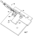
- FIGS. 5-7 are alternative configurations of the clamp and workpiece alignment apparatus of FIG. 1 for clamping different sized workpieces
- FIGS. 8 and 9 illustrate the clamp and workpiece alignment apparatus of FIG. 4 in different configurations.
- FIG. 1 illustrates a clamp 100 in the form of a bench clamp mounted to a workpiece support 102 (e.g. a top of a workbench) according to embodiments of the present invention.
- the workpiece support 102 includes a support surface 104 , e.g. a top surface, upon which workpieces, such as boards 103 , 105 , can be clamped for performing activities on the workpieces 103 , 105 .
- the clamp 100 may clamp the workpieces 103 , 105 adjacent to one another (as illustrated) such that the two workpieces may be affixed to one another such as by way of screws, gluing, dowling, etc.
- the workpiece support 102 has an underside 106 (see FIG. 2 ) opposite the support surface 104 .
- a plurality of apertures 108 extend through the workpiece support to assist in mounting various tools, such as clamp 100 to the workpiece support 102 .
- a clamp mount and workpiece alignment apparatus 120 (referred to herein to as “mount 120 ”) is used to mount the clamp 100 to the workpiece support 102 and particularly adjacent to workpiece support surface 106 . More particularly, in this embodiment, the mount 120 cooperates with the support surface 104 , underside 106 and one of the aperture 108 to mount clamp 100 to the workpiece support 102 .
- the mount 120 assists in positioning one or more workpieces relative to the clamp 100 while the workpiece is supported on a support surface 104 of a workpiece support 102 .
- the mount 120 can be reconfigured to adjust alignment features such that different sized workpieces can be properly positioned relative to the clamp 100 and one another such that the clamp 100 can act on to provide clamping forces to both workpieces simultaneously.
- the illustrated clamp 100 generally includes a handle 122 , a lever arm 124 , a clamp arm 126 , a clamp head 128 , and a clamp base 130 .
- the handle 122 is generally fixed relative to the clamp base 130 .
- the clamp arm 126 is pivotably connected to the clamp base 130 for pivotal movement about axis 132 .
- Lever arm 124 operably acts between the handle 122 and the clamp arm 126 to force clamp arm 126 to pivot about the axis 132 and to bias clamp head 128 toward support surface 104 to clamp workpieces against support surface 104 .
- clamps While one form of a clamp is illustrated, other clamps are contemplated such as clamps that simply have a clamp head 128 that can be actuated by rotation of a threaded rod relative to a threaded base. Further, other structures for actuating the clamp head 128 are contemplated.
- Clamp base 130 includes mounting structure for cooperating with the mount 120 to connect the clamp base 130 to mount 120 .
- the mounting structure is in the form of a threaded hole 136 .
- Mount 120 includes a base 140 , a base mount 142 , a clamp mount 144 , and a workpiece alignment guide 146 .
- the base 140 rests on top of the support surface 106 in use.
- the base mount 142 connects to the base 140 and mounts the base to the support surface 106 .
- the base mount 142 includes an enlarged boss 148 and a first portion of threaded rod 150 .
- the base mount 142 also includes a knob 152 that threadedly engages the first portion of threaded rod 150 .
- the knob 152 includes a threaded nut 154 embedded in a knob body 156 .
- the knob body 156 is able to be gripped for user manipulation.
- the clamp mount 144 is in the form of a second portion of threaded rod 158 that is threadedly received in threaded hole 136 of clamp base 130 .
- first and second portions of threaded rod 150 , 158 have different diameters with the first portion 150 having a smaller diameter than the second portion 158 .
- boss 148 will have a larger diameter than the first and second portions 150 , 158 .
- the first and second portions 150 , 158 and boss 148 are formed from a one-piece component.
- the base mount and particularly first portion of threaded rod 150 could be separate and independent from clamp mount 144 , e.g. second portion of threaded rod 158 .
- boss 148 need not be provided.
- portions 150 and 158 could be one continuous section of threading.
- portions 150 , 158 could have a same diameter.
- the outer peripheral surface of the boss 148 has surface features for improved engagement with the workpieces support.
- the outer peripheral surface, e.g. cylindrical surface, of the boss 148 includes a plurality of axially extending angularly spaced apart grooves. Other surface features could be provided.
- Base mount 142 is only one embodiment of a mount for attaching the mount 120 to the workpiece support 102 .
- Other such devices are contemplated.
- a mount that expands in diameter could be used.
- two wedge shaped pieces that have tapered surfaces that when driven axially toward one another causing the pieces to move radially outward relative to one another to radially engage the inner surfaces of apertures 108 could be used.
- the user will typically attach the clamp mount 144 to the clamp base 130 with the base 140 positioned between boss 148 and clamp base 130 .
- the second portion of threaded rod 158 will extend through aperture 160 in base 140 .
- the workpiece alignment guide 146 properly aligns the workpieces 103 , 105 relative to the clamp 100 such that when the user actuates the clamp arm 126 and clamp head 128 toward the work piece support, the clamp head 128 overlaps and axially clamps both workpieces 103 , 105 . More particularly, the workpiece alignment guide 146 orients the first workpiece 103 and particularly side 162 underneath clamp head 128 such that only a portion of first workpiece 103 is located underneath clamp head 128 . As such, when the second workpiece 105 is butted against side 162 a portion of the second workpiece 105 is also located underneath clamp head 128 .
- the interface 167 between the first and second workpieces 103 , 105 is located below the clamp head 128 .
- the workpiece alignment guide 146 is adjustably positionable relative to the clamp 100 and/or base 140 by way of an adjustment interface 166 between the base 140 and the workpiece alignment guide 146 .
- the adjustment interface 166 is provided by a pair of inward extending pins in the form of projections 168 , 170 that selectively cooperate with (e.g. are selectively removably receivable in) a pair of arrays of recesses 172 A- 172 D and 174 A- 174 D, respectively.
- the arrays of recesses provide individual positions for adjustably positioning the workpiece alignment guide 146 .
- the adjustment interface 166 could provide for infinite adjustability between extreme positions.
- slots and pins could be provided where a knob on the pin could be used to fix the position of the workpiece alignment guide 146 relative to the clamp 100 /base 140 /clamp mount 144 .
- the workpiece alignment guide 146 provides first and second guide regions 176 , 178 for operably positioning the workpieces 103 , 105 relative to the clamp 100 and particularly clamp head 128 .
- the first and second guide regions 176 , 178 are planar walls that are orthogonal to one another that define first and second reference planes that are orthogonal to one another.
- the reference planes are also orthogonal to support surface 104 when the mount 120 is attached to the workpiece support 102 .
- Adjusting which recesses 172 A- 172 D and 174 A- 174 D the projections 168 , 170 are positioned within adjusts the positioning of the first guide region 176 relative to clamp 100 and particularly clamp head 128 .
- the spacing S 1 (see FIG. 4 ) between the first guide region 176 and the clamp mount 144 varies.
- the accounts for first workpieces 103 having different widths W 1 (see FIG. 1 ).
- the recesses 172 A- 172 D and 174 A- 174 D of a given array are spaced apart by one-half inch (1 ⁇ 2′′) to allow for one-half inch (1 ⁇ 2′′) adjustment of the spacing between the clamp mount 144 and the first guide region 176 .
- the spacing is described as being between the clamp mount 144 and the first guide region 176 , the spacing could also be between a given portion of base 140 and the first guide region 176 .
- the spacing could be identified relative to a front side of the base, a rear side of the base, one of the recesses 172 , 174 of the base etc.
- the clamp mount 144 is simply used as an example. Further, this spacing (i.e. distance between the first guide region 176 and point of reference) could be zero in some embodiments.
- the first and second guide regions 176 , 178 of the illustrated embodiment define first and second reference planes for locating the first and second workpieces 103 , 105 .
- recesses 172 A and 174 A are used for a first workpieces 103 with a width W 1 of approximately one and a half inches (1.5′′) and each successive set of recesses (see FIGS. 5-7 ) is used for first work pieces 103 with increasing width W 1 in one-half inch increments such that recesses 172 D and 174 D are used for a first workpiece with width W 1 of three inches (3′′).
- a user can switch between different workpiece sizes (see e.g. workpieces 103 , 103 ′, 103 ′′, 103 ′′′, 105 , 105 ′, 105 ′′ and 105 ′′′) by adjusting the positioning of the workpiece alignment guide 146 .
- the workpiece alignment guide 146 is generally h-shaped.
- the workpiece alignment guide 146 includes a midsection 180 and first and second mounting legs 182 , 184 .
- the legs 182 , 184 extend outward from a first side 186 the midsection 180 .
- the midsection 180 extends longitudinally between opposed ends.
- the first and second mounting legs 182 , 184 are axially offset from one another along a first axis 188 that is generally parallel to first guide region 176 and the reference plane defined thereby.
- first and second legs 182 , 184 extend from the midsection 180 in parallel to one another.
- the first and second legs 182 , 184 and midsection 180 define a base gap 190 therebetween.
- a portion of base 140 is received within base gap 190 .
- more or less of the base 140 may be positioned within base gap 190 , see e.g. FIGS. 5-7 for reference.
- projections 168 , 170 extend laterally inward from inner sides of the corresponding first and second leg 182 , 184 into base gap 190 .
- the first and second legs 182 , 184 could provide the arrays of recesses while the base provides the corresponding projections 168 , 170 that cooperate with the arrays of recesses.
- a third leg 192 in the form of an alignment leg extends from the midsection 180 on a side 194 that is opposite side 186 .
- the third leg 192 provides the second guide region 178 that aligns an end of the first workpiece 103 with a side of the second workpiece 105 .
- the third leg 192 is generally coaxial with the first leg 182 . However, this is not necessary in all embodiments.
- the base could have a bell shaped slot and the clamp could have a corresponding member that is sized to be received through the enlarged portion of the bell shape but not through the smaller portion of the bell shape. This would allow for easy mounting and unmounting of the clamp relative to the base.
Landscapes
- Engineering & Computer Science (AREA)
- Mechanical Engineering (AREA)
- Jigs For Machine Tools (AREA)
Abstract
Description
Claims (15)
Priority Applications (2)
| Application Number | Priority Date | Filing Date | Title |
|---|---|---|---|
| US16/289,124 US11219984B2 (en) | 2019-02-28 | 2019-02-28 | Clamp with workpiece alignment feature |
| DE102020105140.9A DE102020105140A1 (en) | 2019-02-28 | 2020-02-27 | CLAMP WITH WORKPIECE ALIGNMENT FUNCTION |
Applications Claiming Priority (1)
| Application Number | Priority Date | Filing Date | Title |
|---|---|---|---|
| US16/289,124 US11219984B2 (en) | 2019-02-28 | 2019-02-28 | Clamp with workpiece alignment feature |
Publications (2)
| Publication Number | Publication Date |
|---|---|
| US20200276687A1 US20200276687A1 (en) | 2020-09-03 |
| US11219984B2 true US11219984B2 (en) | 2022-01-11 |
Family
ID=72046172
Family Applications (1)
| Application Number | Title | Priority Date | Filing Date |
|---|---|---|---|
| US16/289,124 Expired - Fee Related US11219984B2 (en) | 2019-02-28 | 2019-02-28 | Clamp with workpiece alignment feature |
Country Status (2)
| Country | Link |
|---|---|
| US (1) | US11219984B2 (en) |
| DE (1) | DE102020105140A1 (en) |
Families Citing this family (2)
| Publication number | Priority date | Publication date | Assignee | Title |
|---|---|---|---|---|
| US11219984B2 (en) * | 2019-02-28 | 2022-01-11 | Nomis Llc | Clamp with workpiece alignment feature |
| US20220288749A1 (en) * | 2022-02-06 | 2022-09-15 | Yun Kuan Enterprise Co.,Ltd. | Expandable fixture |
Citations (31)
| Publication number | Priority date | Publication date | Assignee | Title |
|---|---|---|---|---|
| US1026475A (en) | 1911-11-02 | 1912-05-14 | Walter Tarbuck | Clamp. |
| US1820667A (en) | 1930-01-20 | 1931-08-25 | Leyes Louis | Work holding clamp |
| US1954708A (en) | 1933-01-18 | 1934-04-10 | Henry W Mass | Work holding clamp and drill jig |
| US2463966A (en) | 1946-07-09 | 1949-03-08 | Frederick J Hauschild | Clamp mechanism for straightening sheet metal bodies |
| US2577029A (en) | 1948-04-12 | 1951-12-04 | Clyde C Moorehead | Toggle clamp with an adjustable pivot |
| US2627787A (en) | 1951-03-14 | 1953-02-10 | Berthold R Zitner | Machine-tool table work clamp |
| US2658540A (en) | 1950-12-18 | 1953-11-10 | Genevieve Sobaski | Quick-acting hold-down clamp |
| US2705441A (en) | 1951-03-14 | 1955-04-05 | Armstrong Bros Tool Co | Hold-down clamp |
| US2983289A (en) | 1959-01-26 | 1961-05-09 | Pagebar Inc | Table saw for cutting truss members |
| US3124347A (en) | 1964-03-10 | haddad | ||
| US3941364A (en) * | 1974-06-05 | 1976-03-02 | Eldorado Tool And Manufacturing Corporation | Adjustable shaft rest assembly |
| US3984092A (en) | 1975-06-04 | 1976-10-05 | Fitzpatrick John L | Article gripping adapter for clamps |
| US4432538A (en) | 1981-11-30 | 1984-02-21 | Hector Sequin | Machine tool clamp |
| US4470586A (en) | 1982-07-09 | 1984-09-11 | Spencer Philip P | Machine clamp rockable in T slot |
| US4475728A (en) | 1982-07-01 | 1984-10-09 | Haddad Arthur K | Toggle actuated bench clamp |
| US4957402A (en) | 1989-05-05 | 1990-09-18 | Klein Georg D | T-nut with furrows |
| US4989654A (en) | 1990-02-23 | 1991-02-05 | Shopsmith, Inc. | Woodworking workable assembly having an extruded T-slot |
| US5165673A (en) | 1991-11-05 | 1992-11-24 | Newton Jr Brewster L | Fly tying lathe |
| US5443554A (en) | 1993-11-24 | 1995-08-22 | Robert; Denis | Positioning device for woodwork |
| US5584254A (en) | 1994-05-16 | 1996-12-17 | Williams; Willis R. | Collapsible work bench apparatus |
| US5617909A (en) | 1992-09-14 | 1997-04-08 | Duginske; Mark A. | Woodworking machinery jig and fixture system |
| US6394712B1 (en) | 2001-03-15 | 2002-05-28 | Simp'l Products, Inc | Fixture for clamping work pieces for drilling and making pocket hole joints |
| US6715747B2 (en) | 2000-04-12 | 2004-04-06 | Eikichi Nishimura | Jig for positioning and fixing workpiece |
| US6932335B1 (en) * | 2004-04-29 | 2005-08-23 | Delaware Capital Formation, Inc. | Locking clamp |
| US20070267799A1 (en) | 2006-05-18 | 2007-11-22 | Henry Dykstra | T-slot clamp |
| US7980538B1 (en) | 2007-09-10 | 2011-07-19 | Sears Brands, L.L.C. | Clamping jig |
| US8104754B1 (en) | 2008-05-30 | 2012-01-31 | Allen Ip Inc. | Adjustable workpiece positioning and clamping system |
| US9211635B2 (en) | 2013-08-01 | 2015-12-15 | Robert N. Poole | Self-adjusting bar clamp |
| US20160046001A1 (en) * | 2014-08-14 | 2016-02-18 | Kreg Enterprises, Inc. | Expandable locking mechanism and method of use |
| US20200276687A1 (en) * | 2019-02-28 | 2020-09-03 | Nomis Llc | Clamp with workpiece alignment feature |
| US20200338694A1 (en) | 2019-04-26 | 2020-10-29 | Westek Electronics, Inc. | Fosc fixturing strap |
-
2019
- 2019-02-28 US US16/289,124 patent/US11219984B2/en not_active Expired - Fee Related
-
2020
- 2020-02-27 DE DE102020105140.9A patent/DE102020105140A1/en active Pending
Patent Citations (33)
| Publication number | Priority date | Publication date | Assignee | Title |
|---|---|---|---|---|
| US3124347A (en) | 1964-03-10 | haddad | ||
| US1026475A (en) | 1911-11-02 | 1912-05-14 | Walter Tarbuck | Clamp. |
| US1820667A (en) | 1930-01-20 | 1931-08-25 | Leyes Louis | Work holding clamp |
| US1954708A (en) | 1933-01-18 | 1934-04-10 | Henry W Mass | Work holding clamp and drill jig |
| US2463966A (en) | 1946-07-09 | 1949-03-08 | Frederick J Hauschild | Clamp mechanism for straightening sheet metal bodies |
| US2577029A (en) | 1948-04-12 | 1951-12-04 | Clyde C Moorehead | Toggle clamp with an adjustable pivot |
| US2658540A (en) | 1950-12-18 | 1953-11-10 | Genevieve Sobaski | Quick-acting hold-down clamp |
| US2627787A (en) | 1951-03-14 | 1953-02-10 | Berthold R Zitner | Machine-tool table work clamp |
| US2705441A (en) | 1951-03-14 | 1955-04-05 | Armstrong Bros Tool Co | Hold-down clamp |
| US2983289A (en) | 1959-01-26 | 1961-05-09 | Pagebar Inc | Table saw for cutting truss members |
| US3941364A (en) * | 1974-06-05 | 1976-03-02 | Eldorado Tool And Manufacturing Corporation | Adjustable shaft rest assembly |
| US3984092A (en) | 1975-06-04 | 1976-10-05 | Fitzpatrick John L | Article gripping adapter for clamps |
| US4432538A (en) | 1981-11-30 | 1984-02-21 | Hector Sequin | Machine tool clamp |
| US4475728A (en) | 1982-07-01 | 1984-10-09 | Haddad Arthur K | Toggle actuated bench clamp |
| US4470586A (en) | 1982-07-09 | 1984-09-11 | Spencer Philip P | Machine clamp rockable in T slot |
| US4957402A (en) | 1989-05-05 | 1990-09-18 | Klein Georg D | T-nut with furrows |
| US4989654A (en) | 1990-02-23 | 1991-02-05 | Shopsmith, Inc. | Woodworking workable assembly having an extruded T-slot |
| US5165673A (en) | 1991-11-05 | 1992-11-24 | Newton Jr Brewster L | Fly tying lathe |
| US5617909A (en) | 1992-09-14 | 1997-04-08 | Duginske; Mark A. | Woodworking machinery jig and fixture system |
| US5443554A (en) | 1993-11-24 | 1995-08-22 | Robert; Denis | Positioning device for woodwork |
| US5584254A (en) | 1994-05-16 | 1996-12-17 | Williams; Willis R. | Collapsible work bench apparatus |
| US6715747B2 (en) | 2000-04-12 | 2004-04-06 | Eikichi Nishimura | Jig for positioning and fixing workpiece |
| US6394712B1 (en) | 2001-03-15 | 2002-05-28 | Simp'l Products, Inc | Fixture for clamping work pieces for drilling and making pocket hole joints |
| US6932335B1 (en) * | 2004-04-29 | 2005-08-23 | Delaware Capital Formation, Inc. | Locking clamp |
| US20070267799A1 (en) | 2006-05-18 | 2007-11-22 | Henry Dykstra | T-slot clamp |
| US7980538B1 (en) | 2007-09-10 | 2011-07-19 | Sears Brands, L.L.C. | Clamping jig |
| US8104754B1 (en) | 2008-05-30 | 2012-01-31 | Allen Ip Inc. | Adjustable workpiece positioning and clamping system |
| US8469343B2 (en) | 2008-05-30 | 2013-06-25 | Allen Ip, Incorporated | Adjustable track clamp |
| US9120205B2 (en) | 2008-05-30 | 2015-09-01 | Kreg Enterprises, Inc. | Adjustable track clamp |
| US9211635B2 (en) | 2013-08-01 | 2015-12-15 | Robert N. Poole | Self-adjusting bar clamp |
| US20160046001A1 (en) * | 2014-08-14 | 2016-02-18 | Kreg Enterprises, Inc. | Expandable locking mechanism and method of use |
| US20200276687A1 (en) * | 2019-02-28 | 2020-09-03 | Nomis Llc | Clamp with workpiece alignment feature |
| US20200338694A1 (en) | 2019-04-26 | 2020-10-29 | Westek Electronics, Inc. | Fosc fixturing strap |
Non-Patent Citations (5)
| Title |
|---|
| Images of non-patent literature designs known prior to filing date of Feb. 28, 2019; 3 pages. |
| Kreg Tool Company; Bench Clamp Base; pages printed from the internet; date last visited May 28, 2019; https://www.kregtool.com/store/c29/bench-clamps/p433/bench-clamp-base/. |
| Kreg Tool Company; Bench Clamp; pages printed from the internet; date last visited May 28, 2019; https://www.ptreeusa.com/clamp_bench.htm. |
| Kreg Tool Company; Bench Dogs; pages printed from the internet; date last visited May 28, 2019; https://www.ptreeusa.com/clamp_bench_dogs.html. |
| U.S. Appl. No. 29/681,897, Hall, filed Feb. 28, 2019. |
Also Published As
| Publication number | Publication date |
|---|---|
| DE102020105140A1 (en) | 2020-09-03 |
| DE102020105140A8 (en) | 2021-04-01 |
| US20200276687A1 (en) | 2020-09-03 |
Similar Documents
| Publication | Publication Date | Title |
|---|---|---|
| US12496641B2 (en) | Pocket hole jig | |
| JP4823229B2 (en) | Multi-function workpiece clamping device | |
| US7934711B2 (en) | Angle bracket | |
| US9370828B2 (en) | Adjustable doweling jig | |
| US6647847B2 (en) | Fence | |
| US10574040B2 (en) | Cable stripper having an adjustable bushing | |
| US9242348B2 (en) | Interlocking clamp | |
| US8651777B2 (en) | Adjustable doweling jig | |
| US20090272463A1 (en) | Mortising Jig With Extensions | |
| US11219984B2 (en) | Clamp with workpiece alignment feature | |
| US20090020937A1 (en) | Vise understop | |
| WO2013191895A1 (en) | Adjustable doweling jig | |
| US11491601B2 (en) | Multi-joining system | |
| US8020843B2 (en) | Clamping fixture | |
| US11407099B2 (en) | Work surface | |
| US20230055340A1 (en) | Multi-joining system | |
| US20130098502A1 (en) | Edge-band chamfering device | |
| US11090734B1 (en) | Dowel jig | |
| US9821450B2 (en) | Work surface | |
| US6585018B2 (en) | Linear guide for shaping tools | |
| US8678364B2 (en) | Precision leveling vice | |
| US20250262675A1 (en) | Self-Centering Ruler Arrangement for Tool | |
| US12397412B1 (en) | Portable routing system and method of use | |
| US12350781B1 (en) | Portable routing system and method of use | |
| US20230052596A1 (en) | Triple Vice Machining Fixture |
Legal Events
| Date | Code | Title | Description |
|---|---|---|---|
| AS | Assignment |
Owner name: NOMIS LLC, ILLINOIS Free format text: ASSIGNMENT OF ASSIGNORS INTEREST;ASSIGNOR:HALL, TAYLOR JAMES;REEL/FRAME:048471/0032 Effective date: 20190228 |
|
| FEPP | Fee payment procedure |
Free format text: ENTITY STATUS SET TO UNDISCOUNTED (ORIGINAL EVENT CODE: BIG.); ENTITY STATUS OF PATENT OWNER: SMALL ENTITY |
|
| FEPP | Fee payment procedure |
Free format text: ENTITY STATUS SET TO SMALL (ORIGINAL EVENT CODE: SMAL); ENTITY STATUS OF PATENT OWNER: SMALL ENTITY |
|
| STPP | Information on status: patent application and granting procedure in general |
Free format text: NON FINAL ACTION MAILED |
|
| STPP | Information on status: patent application and granting procedure in general |
Free format text: RESPONSE TO NON-FINAL OFFICE ACTION ENTERED AND FORWARDED TO EXAMINER |
|
| STPP | Information on status: patent application and granting procedure in general |
Free format text: NOTICE OF ALLOWANCE MAILED -- APPLICATION RECEIVED IN OFFICE OF PUBLICATIONS |
|
| STPP | Information on status: patent application and granting procedure in general |
Free format text: NOTICE OF ALLOWANCE MAILED -- APPLICATION RECEIVED IN OFFICE OF PUBLICATIONS |
|
| STPP | Information on status: patent application and granting procedure in general |
Free format text: PUBLICATIONS -- ISSUE FEE PAYMENT VERIFIED |
|
| STCF | Information on status: patent grant |
Free format text: PATENTED CASE |
|
| AS | Assignment |
Owner name: BAM IP HOLDING LLC, ILLINOIS Free format text: ASSIGNMENT OF ASSIGNORS INTEREST;ASSIGNOR:NOMIS LLC;REEL/FRAME:069251/0449 Effective date: 20241107 Owner name: BAM IP HOLDING LLC, ILLINOIS Free format text: ASSIGNMENT OF ASSIGNOR'S INTEREST;ASSIGNOR:NOMIS LLC;REEL/FRAME:069251/0449 Effective date: 20241107 |
|
| FEPP | Fee payment procedure |
Free format text: MAINTENANCE FEE REMINDER MAILED (ORIGINAL EVENT CODE: REM.); ENTITY STATUS OF PATENT OWNER: SMALL ENTITY |