US11219944B2 - Casting method for forming screw hole on inclined plane of casting, and casting integrated with insert having screw thread - Google Patents
Casting method for forming screw hole on inclined plane of casting, and casting integrated with insert having screw thread Download PDFInfo
- Publication number
- US11219944B2 US11219944B2 US16/841,071 US202016841071A US11219944B2 US 11219944 B2 US11219944 B2 US 11219944B2 US 202016841071 A US202016841071 A US 202016841071A US 11219944 B2 US11219944 B2 US 11219944B2
- Authority
- US
- United States
- Prior art keywords
- casting
- plug
- mold
- body part
- screw thread
- Prior art date
- Legal status (The legal status is an assumption and is not a legal conclusion. Google has not performed a legal analysis and makes no representation as to the accuracy of the status listed.)
- Active
Links
Images


Classifications
-
- B—PERFORMING OPERATIONS; TRANSPORTING
- B22—CASTING; POWDER METALLURGY
- B22D—CASTING OF METALS; CASTING OF OTHER SUBSTANCES BY THE SAME PROCESSES OR DEVICES
- B22D19/00—Casting in, on, or around objects which form part of the product
- B22D19/009—Casting in, on, or around objects which form part of the product for casting objects the members of which can be separated afterwards
-
- B—PERFORMING OPERATIONS; TRANSPORTING
- B22—CASTING; POWDER METALLURGY
- B22D—CASTING OF METALS; CASTING OF OTHER SUBSTANCES BY THE SAME PROCESSES OR DEVICES
- B22D17/00—Pressure die casting or injection die casting, i.e. casting in which the metal is forced into a mould under high pressure
- B22D17/002—Pressure die casting or injection die casting, i.e. casting in which the metal is forced into a mould under high pressure using movable moulds
-
- B—PERFORMING OPERATIONS; TRANSPORTING
- B22—CASTING; POWDER METALLURGY
- B22C—FOUNDRY MOULDING
- B22C9/00—Moulds or cores; Moulding processes
- B22C9/10—Cores; Manufacture or installation of cores
-
- B—PERFORMING OPERATIONS; TRANSPORTING
- B22—CASTING; POWDER METALLURGY
- B22D—CASTING OF METALS; CASTING OF OTHER SUBSTANCES BY THE SAME PROCESSES OR DEVICES
- B22D17/00—Pressure die casting or injection die casting, i.e. casting in which the metal is forced into a mould under high pressure
- B22D17/20—Accessories: Details
- B22D17/2015—Means for forcing the molten metal into the die
- B22D17/2061—Means for forcing the molten metal into the die using screws
-
- B—PERFORMING OPERATIONS; TRANSPORTING
- B22—CASTING; POWDER METALLURGY
- B22D—CASTING OF METALS; CASTING OF OTHER SUBSTANCES BY THE SAME PROCESSES OR DEVICES
- B22D19/00—Casting in, on, or around objects which form part of the product
-
- B—PERFORMING OPERATIONS; TRANSPORTING
- B22—CASTING; POWDER METALLURGY
- B22D—CASTING OF METALS; CASTING OF OTHER SUBSTANCES BY THE SAME PROCESSES OR DEVICES
- B22D19/00—Casting in, on, or around objects which form part of the product
- B22D19/0072—Casting in, on, or around objects which form part of the product for making objects with integrated channels
Definitions
- Exemplary embodiments of the present disclosure relate to a casting method for forming a fastening part on a casting, more particularly, to the casting method for forming a fastening hole on an inclined plane of the casting and a casting integrated with a screw thread insert.
- a characteristic of being lightweight which may be achieved by changing steel components to aluminum or by weight loss of existing aluminum components, is important, but durability is critically necessary.
- a method for inserting separate female screw thread hardware into an existing aluminum component has been developed.
- a tapping nut 1 for compulsorily pressing a female screw nut as shown in FIG. 1 or a screw thread shape 2 as shown in FIG. 2 are processed and formed on an aluminum component, and then coil-shaped female screw hardware 3 is inserted into the processed aluminum component.
- the related art as described above has problems in that a process for screw tap processing or separate hardware mount should be added after the product is casted, and thus interface bonding performance between hardware and an aluminum mother material is degraded to lower a fastening force. Further, the related art has the problem of weight increase due to the separate hardware.
- Exemplary embodiments of the present disclosure overcome the above disadvantages and other disadvantages not described above, and an object of the present disclosure is to provide a casting method capable of mounting a plug for inserting a screw thread insert into a casting even on the casting having an inclined plane formed thereon, and the casting integrated with a screw thread insert.
- a casting method for forming a fastening part on an inclined plane of a casting includes mounting a plug unit including a casting plug and a screw thread insert combined with the casting plug on a movable mold or a fixed mold; performing casting by moving and combining the movable mold with the fixed mold and injecting a molten metal into a cavity formed between the movable mold and the fixed mold; performing mold opening after the casting; and separating the casting plug from the screw thread insert, wherein when the plug unit is mounted on the mold, the screw thread insert is deployed in the cavity, and a mold plane on which the casting plug is mounted forms an inclined plane having an acute angle against a horizontal plane that is parallel to a movement direction of the movable mold.
- screw thread insert is integrally combined with the casting.
- the casting plug includes a truncated cone shaped plug body part; and a plug screw part projecting from a bottom plane of the plug body part and having male screw threads formed thereon, wherein the screw thread insert has female screw threads formed thereon corresponding to the male screw threads of the plug screw part, and the screw thread insert is combined with the plug screw part.
- an angle of a side plane of the plug body part based on a height direction of the plug body part is greater than or equal to 30°.
- the angle of the side plane of the plug body part based on the height direction of the plug body part is in a range of 30° to 35°.
- the angle of the side plane of the plug body part based on the height direction of the plug body part is greater than or equal to 90° ⁇ (the acute angle of the inclined plane)°.
- the angle of the side plane of the plug body part based on the height direction of the plug body part is in a range of 90° ⁇ (an acute angle of the inclined plane)° to 90° ⁇ (an acute angle of the inclined plane)°+5°.
- a casting in which a fastening part is vertically formed on an inclined plane of the casting based on a movement direction of a mold, and a screw thread insert is integrally combined with the fastening part is provided.
- the present disclosure it is possible to perform the casting by forming a screw thread combination hole even on the inclined plane of the casting through application of the developed plug unit. Accordingly, a separate pressing process is not required, the interface bonding between the screw thread insert and the casting is superior, and the weight increase can be minimized as compared with the existing casting.
- boss part size can be reduced, and thus casting defects can be reduced or eliminated.
- FIGS. 1 and 2 illustrate an example in which a fastening part is formed on a casting in the related art.
- FIG. 3 illustrates a plug unit according to the present disclosure.
- FIGS. 4A and 4B illustrate an example of a casting in which a fastening part is formed on an inclined plane.
- FIG. 5 illustrates a state where a plug unit is mounted on a fastening part of FIGS. 4A and 4B .
- FIG. 6A illustrates a state before a plug unit is removed after casting
- FIG. 6B illustrates a state in which a casting plug of a plug unit is removed after casting.
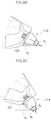
- FIG. 7A illustrates a plug application example in the related art
- FIG. 7B illustrates an example in which a plug is applied to an inclined plane in the related art.
- FIG. 8 is a diagram explaining a plug unit according to the present disclosure.
- FIGS. 9A, 9B, and 9C illustrate the relationship between a plug unit and an inclined plane of a casting according to the present disclosure.
- vehicle or “vehicular” or other similar term as used herein is inclusive of motor vehicles in general such as passenger automobiles including sports utility vehicles (SUV), buses, trucks, various commercial vehicles, watercraft including a variety of boats and ships, aircraft, and the like, and includes hybrid vehicles, electric vehicles, plug-in hybrid electric vehicles, hydrogen-powered vehicles and other alternative fuel vehicles (e.g. fuels derived from resources other than petroleum).
- a hybrid vehicle is a vehicle that has two or more sources of power, for example both gasoline-powered and electric-powered vehicles.
- control logic of the present disclosure may be embodied as non-transitory computer readable media on a computer readable medium containing executable program instructions executed by a processor, controller or the like.
- Examples of computer readable media include, but are not limited to, ROM, RAM, compact disc (CD)-ROMs, magnetic tapes, floppy disks, flash drives, smart cards and optical data storage devices.
- the computer readable medium can also be distributed in network coupled computer systems so that the computer readable media is stored and executed in a distributed fashion, e.g., by a telematics server or a Controller Area Network (CAN).
- a telematics server or a Controller Area Network (CAN).
- CAN Controller Area Network
- FIG. 3 illustrates a plug unit according to the present disclosure.
- FIGS. 4A and 4B illustrate an example of a casting in which a fastening part is formed on an inclined plane
- FIG. 5 illustrates a state where a plug unit is mounted on a fastening part of FIGS. 4A and 4B
- FIG. 6A illustrates a state before a plug unit is removed after casting
- FIG. 6B illustrates a state in which a casting plug of a plug unit is removed after casting.
- the present disclosure is provided so as to cast a casting (casted product) in which a fastening part is formed on an inclined plane of the casting.
- a casting casted product
- the casting is performed using a plug unit 100 , and thus it is possible to manufacture the casting in which a screw thread insert is integrally casted with the fastening part.
- the plug unit 100 is prepared in a manner that a casting plug 110 and a screw thread insert 120 are manufactured and then are combined with each other.
- the casting plug 110 includes a truncated cone shaped plug body part 111 , a plug screw part 112 projecting from a bottom plane of the plug body part 111 and having male screw threads formed thereon, and a planar multi-angle shaped plug head part 113 projecting from an upper plane of the plug body part 111 .
- the screw thread insert 120 is a member on which female screw threads are formed corresponding to the male screw threads of the plug screw part 112 .
- the fastening part is formed on the inclined plane of the casting P to be casted with reference to FIGS. 4 A and 4 B.
- the fastening part may be a fastening hole h, and as can be seen from FIG. 4B and FIG. 5 illustrating portion A of FIG. 4B in an enlarged manner, the fastening hole h is formed on the inclined plane.
- the inclined plane means a slanting plane having an acute angle against a horizontal plane that is parallel to a movement direction for combination of a movable mold and a fixed mold with each other.
- the movable mold and the fixed mold are deployed on left and right sides, and the casting p is casted in the shape of a cavity formed through the combination of the movable and fixed molds.
- a mold plane corresponding to the fastening hole h is also formed as an inclined plane, and in this case, the portion of the casting plug 110 of the plug unit 100 is inserted into the mold to form the mold plane corresponding to the fastening hole h.
- screw thread insert 120 is inserted into the cavity and is integrally combined with the casting P to be casted.
- the plug unit 100 mounted on the inclined plane of the mold forms an acute angle against the horizontal plane, the plug unit can be stably mounted to make the integrated casting possible.
- the plug unit 100 that is combined with the casting P is separated from the mold, and if the casting plug 110 of the plug unit 100 is separated from the screw thread insert 120 , the screw thread insert 120 is integrally formed in the fastening hole of the casting P as shown in FIG. 6B .
- the screw thread insert is inserted and integrally casted at high pressure, and thus post-process problems are originally solved. Further, only minimal hardware is used to form the screw threads on the casting, and thus the weight increase is minimized. Further, in the casting process, an aluminum mother material is closely combined with the hardware, and thus the interface bonding performance becomes prominent.
- the plug should be mounted only in the direction that is parallel to the direction in which the molds m 1 and m 2 are opened and closed, and thus the mold design is restricted.
- the casting becomes possible through inserting of the plug unit.
- the plug body part 111 of the casting plug 110 has a truncated cone shape, and by setting an angle ⁇ of one side plane based on the height direction of the truncated cone shaped plug body part 111 , it is possible to perform the casting in a state where the plug unit 100 is mounted on the mold, and even in the case of the mold opening, it is possible to open the mold without hindering the plug unit 100 .
- FIGS. 9A, 9B, and 9C illustrate angles of side planes of a plug body part 111 according to angles of ⁇ 1 , ⁇ 2 , and ⁇ 3 .
- an angle of the inclined plane ⁇ 1 against the horizontal plane that is parallel to the movement direction of the mold as shown in FIG. 9A is greater than or equal to 60° and is less than or equal to 90°, it is preferable that an angle ⁇ 1 of one side plane based on the height direction of the plug body part 111 is set to be greater than or equal to 30°, and more preferably, the angle ⁇ 1 may be in the range of 30° to 35°.
- the angle ⁇ 1 may be greater than or equal to 90° ⁇ ( ⁇ 1 )°, and in order to facilitate the assembly of the plug unit 100 in size and shape, it may be preferable that the angle ⁇ 1 is in the above-described range.
- the mold opening may be hindered, and if the angle ⁇ 1 exceeds 35°, the mold opening is not hindered, but the volume of the plug body part 111 may be unnecessarily large.
- the angle ⁇ 2 of the side plane of the plug body part 111 is set to be greater than or equal to 90° ⁇ ( ⁇ 2 )°.
- the angle ⁇ 2 may be in the range of 90° ⁇ ( ⁇ 2 )° to 90° ⁇ ( ⁇ 2 )°+5°.
- the mold opening may be hindered, and if the angle ⁇ 2 exceeds 90° ⁇ ( ⁇ 2 )°+5°, the mold opening is not hindered, but the volume of the plug body part 111 may be unnecessarily large.
- the angle ⁇ 3 of the side plane of the plug body part 111 is set to be greater than or equal to 90° ⁇ ( ⁇ 3 )°.
- the angle ⁇ 3 may be in the range of 90° ⁇ ( ⁇ 3 )° to 90° ⁇ ( ⁇ 3 )°+5°.
- the mold opening may be hindered, and if the angle ⁇ 3 exceeds 90° ⁇ ( ⁇ 3 )°+5°, the mold opening is not hindered, but the volume of the plug body part 111 may be unnecessarily large.
- the truncated cone shape of the plug body part 111 may be asymmetric.
- both bodies of the plug body part 111 being divided into two based on the plane which crosses the horizontal plane being in parallel to the movement direction of the mold and on which a vertical line that is at right angles to the cross line is a segment in the length direction of the plug screw part 112 , may be asymmetric to each other.
- the both bodies may be discriminated as an upper body and a lower body.
- the both bodies of the plug body part 111 being divided into two by the above basis may be asymmetric, and may have different volumes, and thus it is not necessary that the angle ⁇ 4 of the side plane of the body having the smaller volume is greater than or equal to 90° ⁇ ( ⁇ 3 )°.
- the angle ⁇ 4 of the side plane of the upper body having the smaller volume may be in the range of ( ⁇ 3 )° to ( ⁇ 3 +5)°.
- the upper body may have the smaller volume
- the lower body may have the smaller volume
- the truncated cone shape of the plug unit may have an asymmetric structure, and in this case, one of the divided bodies may be formed to have a smaller volume than that of the other of the divided bodies.
- the durability of the plug unit 100 mounted on the mold can be secured within the angle range of the side plane of the plug body part 111 , and the force acting on the plug unit 100 during the casting can be minimized. Further, the mold opening is not hindered.
- the height of the plug body part 111 is set to be equal to the length of the plug screw part 112 or the screw thread insert 120 .
Landscapes
- Engineering & Computer Science (AREA)
- Mechanical Engineering (AREA)
- Molds, Cores, And Manufacturing Methods Thereof (AREA)
- Moulds For Moulding Plastics Or The Like (AREA)
Abstract
Description
Claims (7)
Applications Claiming Priority (2)
| Application Number | Priority Date | Filing Date | Title |
|---|---|---|---|
| KR1020200005167A KR102856511B1 (en) | 2020-01-15 | 2020-01-15 | Casting method for forming a screw hole on an inclined plane of a casting and the casting integrated an insert having screw thread |
| KR10-2020-0005167 | 2020-01-15 |
Publications (2)
| Publication Number | Publication Date |
|---|---|
| US20210213516A1 US20210213516A1 (en) | 2021-07-15 |
| US11219944B2 true US11219944B2 (en) | 2022-01-11 |
Family
ID=76760942
Family Applications (1)
| Application Number | Title | Priority Date | Filing Date |
|---|---|---|---|
| US16/841,071 Active US11219944B2 (en) | 2020-01-15 | 2020-04-06 | Casting method for forming screw hole on inclined plane of casting, and casting integrated with insert having screw thread |
Country Status (3)
| Country | Link |
|---|---|
| US (1) | US11219944B2 (en) |
| KR (1) | KR102856511B1 (en) |
| CN (1) | CN113118418B (en) |
Families Citing this family (1)
| Publication number | Priority date | Publication date | Assignee | Title |
|---|---|---|---|---|
| CN113619032A (en) * | 2021-08-09 | 2021-11-09 | 苏州宥安骏精密科技有限公司 | Take screw thread with mould of integrated into one piece product |
Citations (1)
| Publication number | Priority date | Publication date | Assignee | Title |
|---|---|---|---|---|
| KR20190094752A (en) | 2018-02-05 | 2019-08-14 | 엠에이치기술개발 주식회사 | Hollow product manufacturing method and plug for hollow tube plug for the same |
Family Cites Families (7)
| Publication number | Priority date | Publication date | Assignee | Title |
|---|---|---|---|---|
| DE4236084A1 (en) * | 1992-10-26 | 1994-04-28 | Halberg Maschbau Gmbh & Co | Cast part prodn. with shape detail - formed by use of prefabricated insert for forming e.g. threaded bore with end sealing face in pump housing |
| JP2001030048A (en) * | 1999-07-22 | 2001-02-06 | Tokai Kogyo Co Ltd | Metal molding, its molding method and molding die |
| JP4033147B2 (en) * | 2004-02-24 | 2008-01-16 | 株式会社豊田自動織機 | Casting method and casting for castings |
| KR101099504B1 (en) * | 2009-10-14 | 2011-12-27 | 동남정밀 주식회사 | Die casting mold |
| KR20110047297A (en) * | 2009-10-30 | 2011-05-09 | 덕지산업주식회사 | How to form boss part of casting |
| DE102010020682A1 (en) * | 2010-05-15 | 2011-11-17 | Dr. Ing. H.C. F. Porsche Aktiengesellschaft | Metal casting and metal casting |
| CN107206479B (en) * | 2014-03-31 | 2020-06-12 | 伯尔霍夫连接技术有限公司 | Casting moulds, inserts for casting moulds, castings and methods of casting the same |
-
2020
- 2020-01-15 KR KR1020200005167A patent/KR102856511B1/en active Active
- 2020-04-06 US US16/841,071 patent/US11219944B2/en active Active
- 2020-04-16 CN CN202010299360.1A patent/CN113118418B/en active Active
Patent Citations (1)
| Publication number | Priority date | Publication date | Assignee | Title |
|---|---|---|---|---|
| KR20190094752A (en) | 2018-02-05 | 2019-08-14 | 엠에이치기술개발 주식회사 | Hollow product manufacturing method and plug for hollow tube plug for the same |
Also Published As
| Publication number | Publication date |
|---|---|
| US20210213516A1 (en) | 2021-07-15 |
| KR102856511B1 (en) | 2025-09-10 |
| CN113118418B (en) | 2023-08-25 |
| CN113118418A (en) | 2021-07-16 |
| KR20210091905A (en) | 2021-07-23 |
Similar Documents
| Publication | Publication Date | Title |
|---|---|---|
| US20120137749A1 (en) | Press system | |
| US9645051B2 (en) | Automatic examination device of parts for vehicle and method | |
| US11219944B2 (en) | Casting method for forming screw hole on inclined plane of casting, and casting integrated with insert having screw thread | |
| US9321094B2 (en) | Press apparatus for vehicle | |
| US6443831B2 (en) | Transfer register | |
| EP2945471B1 (en) | Integrated power converting apparatus for vehicle | |
| US10252598B2 (en) | Air-conditioning system for a vehicle | |
| US11529857B2 (en) | Cover for door frame of vehicle | |
| US9988088B2 (en) | Structure for connecting strut bar for vehicle | |
| US11241946B2 (en) | Weather strip for vehicle | |
| US20230076155A1 (en) | Vehicle body structure | |
| US11673614B2 (en) | Connecting assembly, method for manufacturing a connecting assembly, vehicle body structure, and method for assembling a vehicle body structure | |
| US10479192B2 (en) | Vehicle radiator having two different colors | |
| US20250276571A1 (en) | Cooling panel for battery case | |
| US20190184455A1 (en) | Vacuum centrifugal casting apparatus | |
| US11065679B2 (en) | Vacuum system for die casting mold | |
| US9469205B2 (en) | Female connector of high voltage junction box and method for assembling the same | |
| CN113085769B (en) | Millimeter wave radar installation fixing structure for automobile automatic driving test | |
| US20240317035A1 (en) | Sealing structure of active weather strip of vehicle and manufacturing method thereof | |
| US20200324828A1 (en) | Vehicle body with reinforced floor | |
| CN218362005U (en) | Automobile-used aluminum alloy housing die casting die | |
| US10625595B2 (en) | Air guide structure of vehicle | |
| CN223664282U (en) | Sliding door matching rapid detection tool | |
| US11820420B2 (en) | Steering shaft temporary support structure of vehicle | |
| CN217570812U (en) | Upper die structure for automobile cover plate |
Legal Events
| Date | Code | Title | Description |
|---|---|---|---|
| AS | Assignment |
Owner name: HYUNDAI MOTOR COMPANY, KOREA, REPUBLIC OF Free format text: ASSIGNMENT OF ASSIGNORS INTEREST;ASSIGNORS:LEE, CHEOL-UNG;LEE, YOON-KI;KIM, JIN-YONG;AND OTHERS;SIGNING DATES FROM 20200312 TO 20200316;REEL/FRAME:052322/0285 Owner name: KIA MOTORS CORPORATION, KOREA, REPUBLIC OF Free format text: ASSIGNMENT OF ASSIGNORS INTEREST;ASSIGNORS:LEE, CHEOL-UNG;LEE, YOON-KI;KIM, JIN-YONG;AND OTHERS;SIGNING DATES FROM 20200312 TO 20200316;REEL/FRAME:052322/0285 Owner name: JINHAP BOLLHOFF LTD., KOREA, REPUBLIC OF Free format text: ASSIGNMENT OF ASSIGNORS INTEREST;ASSIGNORS:LEE, CHEOL-UNG;LEE, YOON-KI;KIM, JIN-YONG;AND OTHERS;SIGNING DATES FROM 20200312 TO 20200316;REEL/FRAME:052322/0285 |
|
| FEPP | Fee payment procedure |
Free format text: ENTITY STATUS SET TO UNDISCOUNTED (ORIGINAL EVENT CODE: BIG.); ENTITY STATUS OF PATENT OWNER: LARGE ENTITY |
|
| STPP | Information on status: patent application and granting procedure in general |
Free format text: RESPONSE TO NON-FINAL OFFICE ACTION ENTERED AND FORWARDED TO EXAMINER |
|
| STPP | Information on status: patent application and granting procedure in general |
Free format text: EX PARTE QUAYLE ACTION MAILED |
|
| STPP | Information on status: patent application and granting procedure in general |
Free format text: RESPONSE TO EX PARTE QUAYLE ACTION ENTERED AND FORWARDED TO EXAMINER |
|
| STPP | Information on status: patent application and granting procedure in general |
Free format text: NOTICE OF ALLOWANCE MAILED -- APPLICATION RECEIVED IN OFFICE OF PUBLICATIONS |
|
| STPP | Information on status: patent application and granting procedure in general |
Free format text: PUBLICATIONS -- ISSUE FEE PAYMENT VERIFIED |
|
| STCF | Information on status: patent grant |
Free format text: PATENTED CASE |
|
| MAFP | Maintenance fee payment |
Free format text: PAYMENT OF MAINTENANCE FEE, 4TH YEAR, LARGE ENTITY (ORIGINAL EVENT CODE: M1551); ENTITY STATUS OF PATENT OWNER: LARGE ENTITY Year of fee payment: 4 |