US11219868B2 - Device for cleaning and method for cleaning water treatment membrane, and water treatment system - Google Patents
Device for cleaning and method for cleaning water treatment membrane, and water treatment system Download PDFInfo
- Publication number
- US11219868B2 US11219868B2 US16/616,890 US201716616890A US11219868B2 US 11219868 B2 US11219868 B2 US 11219868B2 US 201716616890 A US201716616890 A US 201716616890A US 11219868 B2 US11219868 B2 US 11219868B2
- Authority
- US
- United States
- Prior art keywords
- ozone
- water
- ozone gas
- gas
- phase portion
- Prior art date
- Legal status (The legal status is an assumption and is not a legal conclusion. Google has not performed a legal analysis and makes no representation as to the accuracy of the status listed.)
- Active, expires
Links
Images


Classifications
-
- B—PERFORMING OPERATIONS; TRANSPORTING
- B01—PHYSICAL OR CHEMICAL PROCESSES OR APPARATUS IN GENERAL
- B01D—SEPARATION
- B01D61/00—Processes of separation using semi-permeable membranes, e.g. dialysis, osmosis or ultrafiltration; Apparatus, accessories or auxiliary operations specially adapted therefor
- B01D61/14—Ultrafiltration; Microfiltration
- B01D61/22—Controlling or regulating
-
- B—PERFORMING OPERATIONS; TRANSPORTING
- B01—PHYSICAL OR CHEMICAL PROCESSES OR APPARATUS IN GENERAL
- B01D—SEPARATION
- B01D65/00—Accessories or auxiliary operations, in general, for separation processes or apparatus using semi-permeable membranes
- B01D65/02—Membrane cleaning or sterilisation ; Membrane regeneration
-
- B—PERFORMING OPERATIONS; TRANSPORTING
- B01—PHYSICAL OR CHEMICAL PROCESSES OR APPARATUS IN GENERAL
- B01D—SEPARATION
- B01D69/00—Semi-permeable membranes for separation processes or apparatus characterised by their form, structure or properties; Manufacturing processes specially adapted therefor
- B01D69/08—Hollow fibre membranes
-
- B—PERFORMING OPERATIONS; TRANSPORTING
- B01—PHYSICAL OR CHEMICAL PROCESSES OR APPARATUS IN GENERAL
- B01D—SEPARATION
- B01D71/00—Semi-permeable membranes for separation processes or apparatus characterised by the material; Manufacturing processes specially adapted therefor
- B01D71/06—Organic material
- B01D71/30—Polyalkenyl halides
- B01D71/32—Polyalkenyl halides containing fluorine atoms
- B01D71/34—Polyvinylidene fluoride
-
- B—PERFORMING OPERATIONS; TRANSPORTING
- B01—PHYSICAL OR CHEMICAL PROCESSES OR APPARATUS IN GENERAL
- B01D—SEPARATION
- B01D71/00—Semi-permeable membranes for separation processes or apparatus characterised by the material; Manufacturing processes specially adapted therefor
- B01D71/06—Organic material
- B01D71/30—Polyalkenyl halides
- B01D71/32—Polyalkenyl halides containing fluorine atoms
- B01D71/36—Polytetrafluoroethylene
-
- C—CHEMISTRY; METALLURGY
- C02—TREATMENT OF WATER, WASTE WATER, SEWAGE, OR SLUDGE
- C02F—TREATMENT OF WATER, WASTE WATER, SEWAGE, OR SLUDGE
- C02F1/00—Treatment of water, waste water, or sewage
- C02F1/44—Treatment of water, waste water, or sewage by dialysis, osmosis or reverse osmosis
-
- C—CHEMISTRY; METALLURGY
- C02—TREATMENT OF WATER, WASTE WATER, SEWAGE, OR SLUDGE
- C02F—TREATMENT OF WATER, WASTE WATER, SEWAGE, OR SLUDGE
- C02F1/00—Treatment of water, waste water, or sewage
- C02F1/72—Treatment of water, waste water, or sewage by oxidation
- C02F1/78—Treatment of water, waste water, or sewage by oxidation with ozone
-
- B—PERFORMING OPERATIONS; TRANSPORTING
- B01—PHYSICAL OR CHEMICAL PROCESSES OR APPARATUS IN GENERAL
- B01D—SEPARATION
- B01D2321/00—Details relating to membrane cleaning, regeneration, sterilization or to the prevention of fouling
- B01D2321/04—Backflushing
-
- B—PERFORMING OPERATIONS; TRANSPORTING
- B01—PHYSICAL OR CHEMICAL PROCESSES OR APPARATUS IN GENERAL
- B01D—SEPARATION
- B01D2321/00—Details relating to membrane cleaning, regeneration, sterilization or to the prevention of fouling
- B01D2321/16—Use of chemical agents
- B01D2321/168—Use of other chemical agents
-
- B—PERFORMING OPERATIONS; TRANSPORTING
- B01—PHYSICAL OR CHEMICAL PROCESSES OR APPARATUS IN GENERAL
- B01D—SEPARATION
- B01D2321/00—Details relating to membrane cleaning, regeneration, sterilization or to the prevention of fouling
- B01D2321/18—Use of gases
-
- B—PERFORMING OPERATIONS; TRANSPORTING
- B01—PHYSICAL OR CHEMICAL PROCESSES OR APPARATUS IN GENERAL
- B01D—SEPARATION
- B01D2321/00—Details relating to membrane cleaning, regeneration, sterilization or to the prevention of fouling
- B01D2321/18—Use of gases
- B01D2321/185—Aeration
-
- C—CHEMISTRY; METALLURGY
- C02—TREATMENT OF WATER, WASTE WATER, SEWAGE, OR SLUDGE
- C02F—TREATMENT OF WATER, WASTE WATER, SEWAGE, OR SLUDGE
- C02F2101/00—Nature of the contaminant
- C02F2101/30—Organic compounds
-
- C—CHEMISTRY; METALLURGY
- C02—TREATMENT OF WATER, WASTE WATER, SEWAGE, OR SLUDGE
- C02F—TREATMENT OF WATER, WASTE WATER, SEWAGE, OR SLUDGE
- C02F2201/00—Apparatus for treatment of water, waste water or sewage
- C02F2201/78—Details relating to ozone treatment devices
- C02F2201/782—Ozone generators
-
- C—CHEMISTRY; METALLURGY
- C02—TREATMENT OF WATER, WASTE WATER, SEWAGE, OR SLUDGE
- C02F—TREATMENT OF WATER, WASTE WATER, SEWAGE, OR SLUDGE
- C02F2303/00—Specific treatment goals
- C02F2303/16—Regeneration of sorbents, filters
-
- C—CHEMISTRY; METALLURGY
- C02—TREATMENT OF WATER, WASTE WATER, SEWAGE, OR SLUDGE
- C02F—TREATMENT OF WATER, WASTE WATER, SEWAGE, OR SLUDGE
- C02F2303/00—Specific treatment goals
- C02F2303/20—Prevention of biofouling
Definitions
- the present invention relates to a cleaning device and a cleaning method for a water treatment membrane through which organic substances contained in waste water or the like are subjected to membrane separation, and a water treatment system.
- One example of methods for removing organic substances from service water, sewage, waste water such as industrial waste water, or the like containing organic substances is membrane separation using a water treatment membrane.
- a water treatment membrane In such a water treatment system, raw water such as waste water is filtered by a water treatment membrane so that the raw water is separated into organic substances and filtered water.
- removal of organic substances can be stably performed.
- organic substances are adhered to the inside and the surface of the water treatment membrane, so that pores formed in the water treatment membrane may be clogged. When the pores of the water treatment membrane are clogged, the transmembrane pressure increases or the amount of filtered water is reduced, so that the treatment capacity decreases.
- reverse cleaning is generally performed in which cleaning liquid is caused to flow from the filtering secondary side (filtered water side) to the filtering primary side (raw water side) of the water treatment membrane, thereby cleaning the inside and the membrane surface of the water treatment membrane.
- cleaning liquids are used for the reverse cleaning, for example, water or an oxidizing agent aqueous solution such as sodium hypochlorite aqueous solution is used.
- ozone water having high oxidizing power may be used.
- cleaning gas such as ozone gas generated by a gas generator is mixed with a fluid such as water by an ejector (Venturi-type gas-liquid mixing device), to generate a cleaning fluid, and the cleaning fluid is introduced into a water cleaning tank provided with a water treatment membrane (hollow fiber filter), not via a pump (see, for example, Patent Document 2).
- Patent Document 1 For the method described in Patent Document 1, it is necessary to separately provide a compressor for air bubbling, and the like, resulting in a complicated structure and increase in cost.
- the present invention has been made to solve the above problems, and an object of the present invention is to provide a cleaning device and a cleaning method for a water treatment membrane, and a water treatment system, that achieve high usage efficiency of ozone gas with a simple configuration without size increase.
- One aspect of the present invention is directed to a water treatment membrane cleaning device for a water treatment membrane for filtering and treating raw water that is a treatment target, the cleaning device being configured to cause ozone water to flow from a filtering secondary side to a filtering primary side so as to clean the water treatment membrane, the cleaning device including: an ozone gas supply portion for generating and supplying ozone gas; an ozone dissolution tank including a gas phase portion in which the ozone gas is to be accumulated and a liquid phase portion formed by water in which the ozone gas is to be dissolved, the ozone dissolution tank being configured to generate ozone water by dissolving the ozone gas supplied from the ozone gas supply portion, into the water forming the liquid phase portion; first ozone gas supply means for supplying the ozone gas from the ozone gas supply portion to the gas phase portion; second ozone gas supply means for supplying the ozone gas from the ozone gas supply portion to the liquid phase portion; ozone water supply means for supplying the
- Another aspect of the present invention is directed to a water treatment membrane cleaning method for a water treatment membrane for filtering and treating raw water that is a treatment target, the cleaning method causing ozone water to flow from a filtering secondary side to a filtering primary side so as to clean the water treatment membrane, the cleaning method including: an ozone water generation step of, while accumulating undissolved ozone gas in a gas phase portion of an ozone dissolution tank for generating ozone water, supplying ozone gas to a liquid phase portion of the ozone dissolution tank, and dissolving the ozone gas into water forming the liquid phase portion, to generate ozone water, and supplying the undissolved ozone gas to the filtering primary side, to clean a surface of the water treatment membrane; and an ozone water supply step of supplying ozone gas to the gas phase portion, and supplying the ozone water generated in the ozone water generation step to the filtering secondary side by a pressure of the ozone gas in the gas phase portion, so as to clean
- the present invention can provide a cleaning device and a cleaning method for a water treatment membrane, and a water treatment system, that achieve high usage efficiency of ozone gas with a simple configuration without size increase.
- FIG. 1 is a diagram schematically showing the entire configuration of a water treatment system according to embodiment 1 of the present invention.
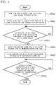
- FIG. 2 is a flowchart showing a cleaning method for a water treatment membrane according to embodiment 1 of the present invention.
- FIG. 3 is a flowchart showing an ozone water generation step according to embodiment 1 of the present invention.
- FIG. 4 is a diagram schematically showing the entire configuration of the water treatment system in the ozone water generation step according to embodiment 1 of the present invention.
- FIG. 5 is a flowchart showing an ozone water supply step according to embodiment 1 of the present invention.
- FIG. 6 is a diagram schematically showing the entire configuration of the water treatment system in the ozone water supply step according to embodiment 1 of the present invention.
- FIG. 1 is a diagram schematically showing the entire configuration of a water treatment system according to embodiment 1.
- FIG. 1 shows the state of the water treatment system in a processing step in which raw water is treated.
- a water treatment system 100 includes: a membrane separation tank 81 having therein a separation membrane 82 , i.e., water treatment membrane, for separating organic substances from raw water which is service water, sewage, industrial waste water, or the like containing organic substances, to perform water treatment, the membrane separation tank 81 being configured such that the outer side of the separation membrane 82 is a filtering primary side 811 and the inner side of the separation membrane 82 is a filtering secondary side 812 ; a cleaning device 10 for cleaning the separation membrane 82 , i.e., a cleaning device for a water treatment membrane; and a treated water tank 91 for temporarily storing raw water treated in the membrane separation tank 81 , as treated water.
- a separation membrane 82 i.e., water treatment membrane
- the cleaning device 10 for the water treatment membrane includes an ozone gas supply portion 11 , and an ozone dissolution tank 12 for generating ozone water.
- the ozone gas supply portion 11 is composed of a source gas supply portion (not shown) and an ozone gas generation portion (not shown) for generating ozone gas using, as a source material, oxygen supplied from the source gas supply portion.
- the source gas generation portion is, for example, an oxygen generation device using a liquid oxygen cylinder, vacuum pressure swing adsorption (VPSA), or the like.
- VPSA vacuum pressure swing adsorption
- the source gas generation portion is not particularly limited as long as the source gas generation portion is a device or the like that can supply oxygen.
- the ozone gas generation portion may be a discharge-type ozone generation device, for example.
- One end of an ozone gas supply pipe 101 is connected to the ozone gas supply portion 11 .
- the other end of the ozone gas supply pipe 101 is connected to an ozone gas flow path switch valve 13 , i.e., ozone gas flow path switch means.
- the ozone gas flow path switch valve 13 is connected to a gas phase portion ozone gas supply pipe 102 , i.e., first ozone gas supply means, and a liquid phase portion ozone gas supply pipe 103 , i.e., second ozone gas supply means.
- the ozone gas flow path switch valve 13 performs open/close operation through control by a control device (not shown), to switch the supply destination of ozone gas supplied from the ozone gas supply pipe 101 , between the gas phase portion ozone gas supply pipe 102 and the liquid phase portion ozone gas supply pipe 103 .
- the ozone dissolution tank 12 has a gas phase portion 121 and a liquid phase portion 122 formed therein.
- the liquid phase portion 122 is an area occupied by liquid, and in embodiment 1, water is used as the liquid forming the liquid phase portion 122 .
- a diffuser device 19 is provided which is connected to the liquid phase portion ozone gas supply pipe 103 and blows ozone gas supplied from the ozone gas supply portion 11 , into the water forming the liquid phase portion 122 .
- the gas phase portion 121 is formed above the liquid phase portion 122 , and serves as a space in which ozone gas is accumulated as described later.
- the top part of the ozone dissolution tank 12 is provided with an ozone gas inflow port 123 to which the gas phase portion ozone gas supply pipe 102 is connected, and an ozone gas outflow port 124 to which a membrane separation tank ozone gas supply pipe 104 , i.e., third ozone gas supply means is connected.
- the bottom part of the ozone dissolution tank 12 is provided with an ozone water outflow port 125 to which an ozone water supply pipe 105 , i.e., ozone water supply means is connected.
- the ozone gas inflow port 123 and the ozone gas outflow port 124 are provided at the top part of the ozone dissolution tank 12 , but the ozone gas inflow port 123 and the ozone gas outflow port 124 may be provided at such positions that allow the gas phase portion 121 to communicate with the gas phase portion ozone gas supply pipe 102 and the membrane separation tank ozone gas supply pipe 104 .
- the ozone water outflow port 125 is provided at the bottom part of the ozone dissolution tank 12 , the ozone water outflow port 125 may be provided at such a position that allows the ozone water supply pipe 105 and the liquid phase portion 122 to communicate with each other.
- the ozone gas supply pipe 101 is provided with an ozone gas supply pressure adjustment valve 15 which performs open/close operation through control by the control device (not shown), to control flow of ozone gas between the ozone gas supply portion 11 and the ozone gas flow path switch valve 13 and adjust the pressure of the ozone gas to be supplied to the secondary side (ozone gas flow path switch valve 13 side) as seen from the ozone gas supply portion 11 .
- the membrane separation tank ozone gas supply pipe 104 is connected to the filtering primary side 811 of the membrane separation tank 81 .
- the membrane separation tank ozone gas supply pipe 104 is provided with an ozone dissolution tank pressure adjustment valve 16 which performs open/close operation through control by the control device (not shown), to control flow of ozone gas flowing through the membrane separation tank ozone gas supply pipe 104 and adjust the pressure of the gas phase portion 121 in the ozone dissolution tank 12 .
- the ozone water supply pipe 105 is connected to the filtering secondary side 812 of the membrane separation tank 81 via a three-way valve 14 and a filtering secondary side flow path pipe 106 .
- the ozone water supply pipe 105 is provided with an ozone water supply pressure adjustment valve 17 which performs open/close operation through control by the control device (not shown), to control flow of ozone water flowing through the ozone water supply pipe 105 and adjust the supply pressure of the ozone water from the liquid phase portion 122 .
- the separation membrane 82 is an organic hollow fiber membrane made from an ozone-resistant material such as polyvinylidene fluoride (PVDF) or polytetrafluoroethylene (PTFE), for example.
- PVDF polyvinylidene fluoride
- PTFE polytetrafluoroethylene
- the filtering primary side 811 of the membrane separation tank 81 is the entrance side for the raw water to be treated, and the filtering secondary side 812 thereof is the exit side for the raw water filtered by the separation membrane 82 .
- the filtering primary side 811 is connected to the membrane separation tank ozone gas supply pipe 104 via a filtering primary side connection portion 813 .
- the filtering secondary side 812 is connected to the filtering secondary side flow path pipe 106 via a filtering secondary side connection portion 814 .
- the treated water tank 91 is connected to the filtering secondary side 812 via the filtering secondary side flow path pipe 106 , the three-way valve 14 , and a treated water transfer pipe 107 .
- the three-way valve 14 performs open/close operation through control by the control device (not shown), to control flow of fluid among the ozone water supply pipe 105 , the filtering secondary side flow path pipe 106 , and the treated water transfer pipe 107 .
- an outlined part in the drawing indicates an opened state or a state in which the part is openable in accordance with the pressure
- a filled part in the drawing indicates a closed state. That is, in FIG. 1 , the ozone gas flow path switch valve 13 is in a closed state in all directions, the three-way valve 14 is in an opened state between the filtering secondary side flow path pipe 106 and the treated water transfer pipe 107 and forms a flow path therebetween, and is in a closed state for the ozone water supply pipe 105 side.
- the ozone gas supply pressure adjustment valve 15 , the ozone dissolution tank pressure adjustment valve 16 , and the ozone water supply pressure adjustment valve 17 are in a closed state.
- the raw water is introduced into the membrane separation tank 81 , and inside the membrane separation tank 81 , flow F 1 of the raw water flowing from the filtering primary side 811 into the filtering secondary side 812 occurs.
- the raw water flowing into the filtering secondary side 812 is filtered by the separation membrane 82 so that organic substances are removed therefrom, and then the filtered water is sent from the filtering secondary side 812 through the filtering secondary side flow path pipe 106 , the three-way valve 14 , and the treated water transfer pipe 107 to the treated water tank 91 .
- the treated water sent to the treated water tank 91 is temporarily stored therein, and then discharged to the outside of the system.
- FIG. 2 is a flowchart showing a cleaning method for the water treatment membrane according to embodiment 1.
- the cleaning method for the water treatment membrane in the present invention includes two steps, i.e., an ozone water generation step (step ST 01 ), and an ozone water supply step (step ST 02 ) subsequent to the ozone water generation step. Each step will be described below.
- FIG. 3 is a flowchart showing the ozone water generation step according to embodiment 1
- FIG. 4 is a diagram schematically showing the entire configuration of the water treatment system in the ozone water generation step according to embodiment 1.
- the ozone gas flow path switch valve 13 is opened between the ozone gas supply pipe 101 and the liquid phase portion ozone gas supply pipe 103 , to form a flow path between the ozone gas supply portion 11 and the diffuser device 19 (step ST 011 ).
- the ozone gas flow path switch valve 13 is closed for the gas phase portion ozone gas supply pipe 102 side, to interrupt flow between the ozone gas supply portion 11 and the gas phase portion 121 .
- the ozone water supply pressure adjustment valve 17 is closed.
- the opened/closed state of the ozone dissolution tank pressure adjustment valve 16 is controlled by the pressure of the gas phase portion 121 as described later.
- the ozone gas supply portion 11 is activated to send ozone gas to the diffuser device 19 , and the ozone gas is supplied to the liquid phase portion 122 through the diffuser device 19 (step ST 012 ).
- the set pressure value of the ozone gas supply pressure adjustment valve 15 is equal to or greater than the value of the hydraulic head pressure applied to the diffuser device 19 .
- the set pressure value of the ozone dissolution tank pressure adjustment valve 16 is smaller than a pressure value obtained by subtracting the value of the hydraulic head pressure applied to the diffuser device 19 , from the set pressure value of the ozone gas supply pressure adjustment valve 15 . Setting the pressure value for the ozone dissolution tank pressure adjustment valve 16 as described above allows the ozone gas to be continuously supplied into the liquid phase portion 122 from the diffuser device 19 .
- the ozone gas supplied to the liquid phase portion 122 is partially dissolved in the water in the liquid phase portion 122 , and the rest of the ozone gas is accumulated in the gas phase portion 121 as undissolved ozone gas.
- the undissolved ozone gas accumulated in the gas phase portion 121 increases the pressure of the ozone gas in the gas phase portion 121 .
- the saturation solubility of gas to water increases as the pressure of the gas increases. Therefore, the saturation solubility of ozone to water forming the liquid phase portion 122 increases with accumulation of the undissolved ozone gas in the gas phase portion 121 .
- step ST 013 When the pressure value of the gas phase portion 121 has become equal to or greater than the set pressure value of the ozone dissolution tank pressure adjustment valve 16 (step ST 013 ), a part of the undissolved ozone gas flows out from the ozone gas outflow port 124 and is supplied to the filtering primary side 811 of the membrane separation tank 81 via the membrane separation tank ozone gas supply pipe 104 (step ST 014 ).
- the undissolved ozone gas supplied to the filtering primary side 811 becomes bubbles in the filtering primary side 811 , and flows in the filtering primary side 811 as indicated by flow F 2 of the undissolved ozone gas shown in FIG. 4 .
- the bubbles of the undissolved ozone gas flowing in the filtering primary side 811 peels and removes organic substances adhered to the membrane surface of the separation membrane 82 by a physical action due to shearing force and a chemical action of the ozone gas as an oxidizing gas, thereby cleaning the membrane surface of the separation membrane 82 (step ST 015 ).
- the undissolved ozone gas supplied to the filtering primary side 811 acts as an aeration gas for cleaning the membrane surface.
- the undissolved ozone gas is consumed in the membrane separation tank, and contamination of the separation membrane 82 is reduced.
- the ozone water generation step is finished, to proceed to the next step, i.e., the ozone water supply step (step ST 016 ).
- the set concentration value is a predetermined value close to the saturation solubility. The higher the dissolved ozone concentration is, the higher the cleaning effect for the separation membrane 82 is. Therefore, it is preferable that the set concentration value is as close to the saturation solubility as possible.
- the saturation solubility varies depending on the temperature, pH, and the pressure of the solvent.
- the set concentration value may be a constant value equal to or greater than 30 mg/L, for example.
- an air diffusion period required for the dissolved ozone concentration to reach the set concentration value may be calculated in advance, and in the actual ozone water generation step, the air diffusion period may be set instead of the set concentration value.
- FIG. 5 is a flowchart showing the ozone water supply step according to embodiment 1
- FIG. 6 is a diagram schematically showing the entire configuration of the water treatment system in the ozone water supply step according to embodiment 1.
- the ozone gas flow path switch valve 13 is opened between the ozone gas supply pipe 101 and the gas phase portion ozone gas supply pipe 102 , to form a flow path between the ozone gas supply portion 11 and the gas phase portion 121 , and is closed for the liquid phase portion ozone gas supply pipe 103 side, thereby switching the supply destination of the ozone gas from the liquid phase portion 122 to the gas phase portion 121 (step ST 021 ).
- the ozone dissolution tank pressure adjustment valve 16 is closed.
- the opened/closed state of the ozone water supply pressure adjustment valve 17 is controlled by the supply pressure of the ozone water as described later.
- the three-way valve 14 is opened between the ozone water supply pipe 105 and the filtering secondary side flow path pipe 106 , to form a flow path between the liquid phase portion 122 and the filtering secondary side, and is closed for the treated water transfer pipe 107 side, thereby switching the flow path of the three-way valve 14 .
- ozone gas is supplied to the gas phase portion 121 through the ozone gas inflow port 123 , and the ozone water in the liquid phase portion 122 is transferred using the pressure of the ozone gas in the gas phase portion 121 as a drive force, so as to be supplied to the filtering secondary side 812 of the membrane separation tank 81 (step ST 022 ).
- the pressure in the gas phase portion 121 increases with supply of the ozone gas to the gas phase portion 121 , whereby a sufficient pressure for transferring the ozone water to the filtering secondary side 812 can be obtained.
- the ozone water in the liquid phase portion 122 flows out through the ozone water outflow port 125 , passes through the ozone water supply pipe 105 , the three-way valve 14 , and the filtering secondary side flow path pipe 106 , and flows into the filtering secondary side 812 .
- the ozone water is supplied to the filtering secondary side 812 , impurities such as organic suspended substances clogged inside the membrane are dissolved in the filtering secondary side 812 , whereby the inside of the separation membrane 82 is cleaned.
- the ozone water after used for the cleaning flows from the filtering secondary side to the filtering primary side 811 as indicated by flow F 3 of the ozone water shown in FIG. 6 (step ST 023 ).
- the drive force for causing the ozone water to flow from the filtering secondary side 812 to the filtering primary side 811 is based on a pressure from the gas phase portion 121 , as in the transfer of the ozone water. From the standpoint of the cleaning effect for the separation membrane 82 or preventing ozone from being isolated again in the ozone water during the transfer, it is preferable that the ozone water is supplied to the filtering secondary side 812 with a supply pressure as high as possible. However, if a pressure applied to the separation membrane 82 due to flow of the ozone water is excessively high, there is a possibility that the pressure exceeds the withstand pressure of the separation membrane 82 and thus the separation membrane 82 is damaged.
- the ozone water supply pressure adjustment valve 17 is controlled so as to reduce such an excessive supply pressure, and thus the pressure of the ozone water supplied to the filtering secondary side 812 is adjusted, whereby the pressure applied to the separation membrane 82 due to flow of the ozone water is prevented from becoming excessively high.
- the set pressure value of the ozone water supply pressure adjustment valve 17 is not less than the set pressure value of the ozone dissolution tank pressure adjustment valve 16 and not greater than 300 kPa.
- the time required for cleaning the separation membrane 82 which depends on the size or the contamination degree of the separation membrane 82 , is conceivably about 30 minutes.
- supply of the ozone gas from the ozone gas supply portion 11 to the gas phase portion 121 is continued and supply of the ozone water to the filtering secondary side 812 is continued, and thereafter, the supply of the ozone gas from the ozone gas supply portion 11 is stopped and thus the ozone water supply step is finished.
- the usage efficiency of ozone gas can be enhanced with a simple configuration without size increase.
- the gas phase portion ozone gas supply pipe and the liquid phase portion ozone gas supply pipe are provided so that ozone gas can be supplied to each of the gas phase portion and the liquid phase portion of the ozone dissolution tank for generating ozone water.
- the supply destination of the ozone gas is switched so as to supply the ozone gas to the gas phase portion, and with the pressure of the ozone gas applied from the gas phase portion side, the ozone water is supplied to the membrane separation tank.
- the pressure applied to the ozone water is kept, and the ozone water can be transferred to the membrane separation tank while a high saturation solubility is maintained.
- the ozone is prevented from being isolated again, and the usage efficiency of the ozone gas is enhanced.
- the cleaning for the separation membrane is performed with use of only ozone water, and a circulation path for increasing the dissolved ozone concentration is not needed. Therefore, the configuration is simplified and increase in cost can be prevented.
- the ozone gas supplied to the gas phase portion and the undissolved ozone gas are used for increasing the pressure of the gas phase portion, and ozone in the ozone water used for the cleaning is consumed before the ozone water flows out to the filtering primary side. Therefore, a device for treating waste ozone gas, such as a reducing device using a catalyst, activated carbon, or the like, is not needed. Thus, size increase in the apparatus can be prevented, and increase in cost can be prevented.
- the membrane surface of the separation membrane is cleaned from the filtering primary side, using bubbles of undissolved ozone gas in the ozone water generation step.
- the usage efficiency of ozone can be further enhanced.
- the supply pressure in the ozone water supply step can be reduced and the cleaning period can be shortened, whereby the amount of ozone gas required for the cleaning can be decreased.
- the undissolved ozone gas is consumed by being caused to react with sludge on the membrane surface or the filtering primary side. Therefore, it is not necessary to treat the undissolved ozone gas as waste ozone gas.
- one ozone gas supply portion is provided and the supply destination of the ozone gas is switched by the ozone gas flow path switch valve, between the liquid phase portion and the gas phase portion of the ozone dissolution tank.
- ozone gas supply portions may be respectively provided for the gas phase portion and the liquid phase portion.
- the ozone gas supply portion for the gas phase portion is connected to the gas phase portion ozone gas supply pipe and supplies ozone gas to only the gas phase portion
- the ozone gas supply portion for the liquid phase portion is connected to the liquid phase portion ozone gas supply pipe and supplies ozone gas to only the liquid phase portion. Therefore, the ozone gas flow path switch valve can be omitted.
Landscapes
- Chemical & Material Sciences (AREA)
- Chemical Kinetics & Catalysis (AREA)
- Engineering & Computer Science (AREA)
- Water Supply & Treatment (AREA)
- Life Sciences & Earth Sciences (AREA)
- Hydrology & Water Resources (AREA)
- Environmental & Geological Engineering (AREA)
- Organic Chemistry (AREA)
- Separation Using Semi-Permeable Membranes (AREA)
- Treatment Of Water By Oxidation Or Reduction (AREA)
Abstract
Description
-
- Patent Document 1: Japanese Laid-Open Patent Publication No. 2001-79365 (paragraph [0006] of the specification,
FIG. 1 ) - Patent Document 2: Japanese Laid-Open Patent Publication No. 2012-96209 (paragraphs [0022] to [0027] of the specification,
FIG. 1 toFIG. 5 ) - Patent Document 3: Japanese Laid-Open Patent Publication No. 06-64904 (paragraphs [0014] and [0015] of the specification,
FIG. 1 )
- Patent Document 1: Japanese Laid-Open Patent Publication No. 2001-79365 (paragraph [0006] of the specification,
-
- 10 cleaning device
- 11 ozone gas supply portion
- 12 ozone dissolution tank
- 13 ozone gas flow path switch valve
- 15 ozone gas supply pressure adjustment valve
- 16 ozone dissolution tank pressure adjustment valve
- 17 ozone water supply pressure adjustment valve
- 81 membrane separation tank
- 82 separation membrane
- 100 water treatment system
- 101 ozone gas supply pipe
- 102 gas phase portion ozone gas supply pipe
- 103 liquid phase portion ozone gas supply pipe
- 104 membrane separation tank ozone gas supply pipe
- 105 ozone water supply pipe
- 121 gas phase portion
- 122 liquid phase portion
- 811 filtering primary side
- 812 filtering secondary side
Claims (6)
Applications Claiming Priority (1)
| Application Number | Priority Date | Filing Date | Title |
|---|---|---|---|
| PCT/JP2017/021135 WO2018225186A1 (en) | 2017-06-07 | 2017-06-07 | Device for cleaning and method for cleaning water treatment membrane, and water treatment system |
Publications (2)
| Publication Number | Publication Date |
|---|---|
| US20210170340A1 US20210170340A1 (en) | 2021-06-10 |
| US11219868B2 true US11219868B2 (en) | 2022-01-11 |
Family
ID=61074715
Family Applications (1)
| Application Number | Title | Priority Date | Filing Date |
|---|---|---|---|
| US16/616,890 Active 2037-07-29 US11219868B2 (en) | 2017-06-07 | 2017-06-07 | Device for cleaning and method for cleaning water treatment membrane, and water treatment system |
Country Status (5)
| Country | Link |
|---|---|
| US (1) | US11219868B2 (en) |
| JP (1) | JP6271109B1 (en) |
| KR (1) | KR102263669B1 (en) |
| CN (1) | CN110709153B (en) |
| WO (1) | WO2018225186A1 (en) |
Families Citing this family (6)
| Publication number | Priority date | Publication date | Assignee | Title |
|---|---|---|---|---|
| WO2020255201A1 (en) * | 2019-06-17 | 2020-12-24 | 三菱電機株式会社 | Filtration membrane cleaning apparatus, filtration membrane cleaning method and water treatment system |
| JP7567335B2 (en) * | 2019-09-30 | 2024-10-16 | 東レ株式会社 | Fermentation liquid filtration method |
| WO2021191997A1 (en) * | 2020-03-24 | 2021-09-30 | 三菱電機株式会社 | Membrane cleaning device, membrane bioreactor system, and membrane cleaning method |
| CN115702116B (en) * | 2020-06-08 | 2024-09-13 | 三菱电机株式会社 | Ozone water production device, water treatment device and ozone water production method |
| US12509382B2 (en) | 2021-08-25 | 2025-12-30 | Saudi Arabian Oil Company | Controlling biofouling in water purification |
| ES3039521R1 (en) * | 2022-12-28 | 2026-02-19 | Univ Catolica Del Norte | SYSTEM AND PROCEDURE FOR CHEMICAL CONVERSION OF REVERSE OSMOSIS MEMBRANES |
Citations (8)
| Publication number | Priority date | Publication date | Assignee | Title |
|---|---|---|---|---|
| JPH0664904U (en) | 1993-02-22 | 1994-09-13 | 有限会社ポ−リア・ミズ | Seal |
| US5607593A (en) * | 1993-11-30 | 1997-03-04 | Otv Omnium De Trajtements Et De Valorisation S.A. | Installation for making water potable with submerged filtering membranes |
| JP2001070761A (en) | 1999-09-02 | 2001-03-21 | Kubota Corp | Backwashing method and apparatus for immersion type membrane separation device |
| JP2001079365A (en) | 1999-09-09 | 2001-03-27 | Asahi Kasei Corp | Cleaning method |
| JP2002292257A (en) | 2001-03-30 | 2002-10-08 | Kuraray Co Ltd | Cleaning method for hollow fiber membrane module |
| JP2004344833A (en) | 2003-05-26 | 2004-12-09 | Oriental Kiden Kk | Ozone water treatment plant |
| JP2010199124A (en) | 2009-02-23 | 2010-09-09 | Nomura Micro Sci Co Ltd | Apparatus for supplying ozone water |
| JP2012096209A (en) | 2010-11-05 | 2012-05-24 | Sharp Corp | Cleaning water tank, water cleaning unit and method for cleaning water cleaning unit |
Family Cites Families (6)
| Publication number | Priority date | Publication date | Assignee | Title |
|---|---|---|---|---|
| JPH0664904A (en) * | 1992-08-20 | 1994-03-08 | Fuji Electric Co Ltd | Ozone water production equipment |
| JP3700932B2 (en) * | 2001-07-26 | 2005-09-28 | 株式会社荏原製作所 | Method and apparatus for cleaning filter using ozone |
| JPWO2009128328A1 (en) * | 2008-04-14 | 2011-08-04 | 栗田工業株式会社 | Operation method of reverse osmosis membrane module |
| CN101935138A (en) * | 2010-09-07 | 2011-01-05 | 东北电力大学 | Submerged membrane bioreactor with automatic online washing function |
| SG11201608368QA (en) * | 2014-04-10 | 2016-11-29 | Mitsubishi Electric Corp | Water treatment method and water treatment apparatus each using membrane |
| CN105060458A (en) * | 2015-07-21 | 2015-11-18 | 黑龙江大学 | Water-purification device by utilizing catalytic oxidation of ozone-PVDF hybrid membrane |
-
2017
- 2017-06-07 JP JP2017556273A patent/JP6271109B1/en active Active
- 2017-06-07 CN CN201780091540.7A patent/CN110709153B/en active Active
- 2017-06-07 WO PCT/JP2017/021135 patent/WO2018225186A1/en not_active Ceased
- 2017-06-07 KR KR1020197034718A patent/KR102263669B1/en active Active
- 2017-06-07 US US16/616,890 patent/US11219868B2/en active Active
Patent Citations (8)
| Publication number | Priority date | Publication date | Assignee | Title |
|---|---|---|---|---|
| JPH0664904U (en) | 1993-02-22 | 1994-09-13 | 有限会社ポ−リア・ミズ | Seal |
| US5607593A (en) * | 1993-11-30 | 1997-03-04 | Otv Omnium De Trajtements Et De Valorisation S.A. | Installation for making water potable with submerged filtering membranes |
| JP2001070761A (en) | 1999-09-02 | 2001-03-21 | Kubota Corp | Backwashing method and apparatus for immersion type membrane separation device |
| JP2001079365A (en) | 1999-09-09 | 2001-03-27 | Asahi Kasei Corp | Cleaning method |
| JP2002292257A (en) | 2001-03-30 | 2002-10-08 | Kuraray Co Ltd | Cleaning method for hollow fiber membrane module |
| JP2004344833A (en) | 2003-05-26 | 2004-12-09 | Oriental Kiden Kk | Ozone water treatment plant |
| JP2010199124A (en) | 2009-02-23 | 2010-09-09 | Nomura Micro Sci Co Ltd | Apparatus for supplying ozone water |
| JP2012096209A (en) | 2010-11-05 | 2012-05-24 | Sharp Corp | Cleaning water tank, water cleaning unit and method for cleaning water cleaning unit |
Non-Patent Citations (4)
| Title |
|---|
| Chinese Office Action dated Aug. 3, 2021 in corresponding Chinese Patent Application No. 201780091540.7. 17 pages with English translation. |
| International Search Report (with English Translation) and Written Opinion issued in corresponding International Patent Application No. PCT/JP2017/021135, 11 pages (dated Jul. 18, 2017). |
| Office Action dated Nov. 23, 2020, issued in corresponding Korean Patent Application No. 10-2019-7034718, 13 pages including 7 pages of English translation. |
| Office Action dated Sep. 2, 2020, issued in corresponding Indian Patent Application No. 201927045963, 5 pages. |
Also Published As
| Publication number | Publication date |
|---|---|
| JPWO2018225186A1 (en) | 2019-06-27 |
| CN110709153B (en) | 2022-03-01 |
| CN110709153A (en) | 2020-01-17 |
| JP6271109B1 (en) | 2018-01-31 |
| KR102263669B1 (en) | 2021-06-10 |
| KR20190136105A (en) | 2019-12-09 |
| WO2018225186A1 (en) | 2018-12-13 |
| US20210170340A1 (en) | 2021-06-10 |
Similar Documents
| Publication | Publication Date | Title |
|---|---|---|
| US11219868B2 (en) | Device for cleaning and method for cleaning water treatment membrane, and water treatment system | |
| JP2007289940A (en) | Cleaning method for hollow fiber membrane module | |
| WO2019039155A1 (en) | Water treatment membrane cleaning apparatus and cleaning method membrane | |
| WO2013176145A1 (en) | Cleaning method for separation membrane module | |
| CN113966249B (en) | Filter membrane cleaning device, filter membrane cleaning method and water treatment system | |
| JP2004033889A (en) | Air diffusion method and air diffusion system | |
| JP3777376B2 (en) | Water purifier and control method thereof | |
| WO2015190948A1 (en) | Liquid purification method and system for the implementation thereof | |
| CN118613321B (en) | Filter membrane cleaning device, water treatment device and filter membrane cleaning method | |
| JP4984460B2 (en) | Separation membrane cleaning method and organic sewage treatment apparatus | |
| JP2014172014A (en) | Membrane separation device and membrane separation method | |
| JP2003010661A (en) | Carbonated water production device and method of operating carbonated water production device | |
| WO2012157668A1 (en) | Filtration apparatus and method for washing filtration apparatus | |
| EP3725393B1 (en) | Filtering membrane cleaning method | |
| JP7705754B2 (en) | Wastewater treatment device and method for cleaning the same | |
| JP2005081237A (en) | Sludge reduction method | |
| JP7067678B1 (en) | Filtration membrane cleaning equipment, water treatment equipment and filtration membrane cleaning method | |
| JP4244001B2 (en) | Membrane cleaning method for membrane activated sludge treatment equipment | |
| JP2016137469A (en) | Method and device for cleaning air diffusion pipe, and activated sludge treatment method and activated sludge treatment system | |
| JP2013075291A (en) | Membrane filtration system and operation control method of the same | |
| JP2017064580A (en) | Water treatment system | |
| JP2000288373A (en) | Ozone water supply device for easy intermittent supply | |
| JP2005211825A (en) | Biological waste liquid treatment apparatus | |
| JP2007260482A (en) | Reverse osmosis unit | |
| JP2017064577A (en) | Carbon dioxide removal membrane apparatus and water treatment system |
Legal Events
| Date | Code | Title | Description |
|---|---|---|---|
| AS | Assignment |
Owner name: MITSUBISHI ELECTRIC CORPORATION, JAPAN Free format text: ASSIGNMENT OF ASSIGNORS INTEREST;ASSIGNORS:KOGA, HIROMICHI;TOKIMORI, KOICHI;GOTO, SHINSUKE;REEL/FRAME:051109/0220 Effective date: 20191001 |
|
| FEPP | Fee payment procedure |
Free format text: ENTITY STATUS SET TO UNDISCOUNTED (ORIGINAL EVENT CODE: BIG.); ENTITY STATUS OF PATENT OWNER: LARGE ENTITY |
|
| STPP | Information on status: patent application and granting procedure in general |
Free format text: RESPONSE TO NON-FINAL OFFICE ACTION ENTERED AND FORWARDED TO EXAMINER |
|
| STPP | Information on status: patent application and granting procedure in general |
Free format text: FINAL REJECTION MAILED |
|
| STPP | Information on status: patent application and granting procedure in general |
Free format text: RESPONSE AFTER FINAL ACTION FORWARDED TO EXAMINER |
|
| STPP | Information on status: patent application and granting procedure in general |
Free format text: NOTICE OF ALLOWANCE MAILED -- APPLICATION RECEIVED IN OFFICE OF PUBLICATIONS |
|
| STPP | Information on status: patent application and granting procedure in general |
Free format text: NOTICE OF ALLOWANCE MAILED -- APPLICATION RECEIVED IN OFFICE OF PUBLICATIONS |
|
| STPP | Information on status: patent application and granting procedure in general |
Free format text: PUBLICATIONS -- ISSUE FEE PAYMENT VERIFIED |
|
| STCF | Information on status: patent grant |
Free format text: PATENTED CASE |
|
| MAFP | Maintenance fee payment |
Free format text: PAYMENT OF MAINTENANCE FEE, 4TH YEAR, LARGE ENTITY (ORIGINAL EVENT CODE: M1551); ENTITY STATUS OF PATENT OWNER: LARGE ENTITY Year of fee payment: 4 |