US11219568B2 - Standing assistance apparatus - Google Patents
Standing assistance apparatus Download PDFInfo
- Publication number
- US11219568B2 US11219568B2 US16/166,158 US201816166158A US11219568B2 US 11219568 B2 US11219568 B2 US 11219568B2 US 201816166158 A US201816166158 A US 201816166158A US 11219568 B2 US11219568 B2 US 11219568B2
- Authority
- US
- United States
- Prior art keywords
- case
- guide
- support part
- support
- shaft
- Prior art date
- Legal status (The legal status is an assumption and is not a legal conclusion. Google has not performed a legal analysis and makes no representation as to the accuracy of the status listed.)
- Active, expires
Links
Images


Classifications
-
- A—HUMAN NECESSITIES
- A61—MEDICAL OR VETERINARY SCIENCE; HYGIENE
- A61G—TRANSPORT, PERSONAL CONVEYANCES, OR ACCOMMODATION SPECIALLY ADAPTED FOR PATIENTS OR DISABLED PERSONS; OPERATING TABLES OR CHAIRS; CHAIRS FOR DENTISTRY; FUNERAL DEVICES
- A61G7/00—Beds specially adapted for nursing; Devices for lifting patients or disabled persons
- A61G7/10—Devices for lifting patients or disabled persons, e.g. special adaptations of hoists thereto
- A61G7/1013—Lifting of patients by
- A61G7/1017—Pivoting arms, e.g. crane type mechanisms
-
- A—HUMAN NECESSITIES
- A61—MEDICAL OR VETERINARY SCIENCE; HYGIENE
- A61G—TRANSPORT, PERSONAL CONVEYANCES, OR ACCOMMODATION SPECIALLY ADAPTED FOR PATIENTS OR DISABLED PERSONS; OPERATING TABLES OR CHAIRS; CHAIRS FOR DENTISTRY; FUNERAL DEVICES
- A61G7/00—Beds specially adapted for nursing; Devices for lifting patients or disabled persons
- A61G7/10—Devices for lifting patients or disabled persons, e.g. special adaptations of hoists thereto
- A61G7/1013—Lifting of patients by
- A61G7/1015—Cables, chains or cords
-
- A—HUMAN NECESSITIES
- A61—MEDICAL OR VETERINARY SCIENCE; HYGIENE
- A61G—TRANSPORT, PERSONAL CONVEYANCES, OR ACCOMMODATION SPECIALLY ADAPTED FOR PATIENTS OR DISABLED PERSONS; OPERATING TABLES OR CHAIRS; CHAIRS FOR DENTISTRY; FUNERAL DEVICES
- A61G7/00—Beds specially adapted for nursing; Devices for lifting patients or disabled persons
- A61G7/10—Devices for lifting patients or disabled persons, e.g. special adaptations of hoists thereto
- A61G7/1013—Lifting of patients by
- A61G7/1019—Vertical extending columns or mechanisms
-
- A—HUMAN NECESSITIES
- A61—MEDICAL OR VETERINARY SCIENCE; HYGIENE
- A61G—TRANSPORT, PERSONAL CONVEYANCES, OR ACCOMMODATION SPECIALLY ADAPTED FOR PATIENTS OR DISABLED PERSONS; OPERATING TABLES OR CHAIRS; CHAIRS FOR DENTISTRY; FUNERAL DEVICES
- A61G7/00—Beds specially adapted for nursing; Devices for lifting patients or disabled persons
- A61G7/10—Devices for lifting patients or disabled persons, e.g. special adaptations of hoists thereto
- A61G7/104—Devices carried or supported by
- A61G7/1046—Mobile bases, e.g. having wheels
-
- A—HUMAN NECESSITIES
- A61—MEDICAL OR VETERINARY SCIENCE; HYGIENE
- A61G—TRANSPORT, PERSONAL CONVEYANCES, OR ACCOMMODATION SPECIALLY ADAPTED FOR PATIENTS OR DISABLED PERSONS; OPERATING TABLES OR CHAIRS; CHAIRS FOR DENTISTRY; FUNERAL DEVICES
- A61G7/00—Beds specially adapted for nursing; Devices for lifting patients or disabled persons
- A61G7/10—Devices for lifting patients or disabled persons, e.g. special adaptations of hoists thereto
- A61G7/1049—Attachment, suspending or supporting means for patients
- A61G7/1059—Seats
-
- A—HUMAN NECESSITIES
- A61—MEDICAL OR VETERINARY SCIENCE; HYGIENE
- A61G—TRANSPORT, PERSONAL CONVEYANCES, OR ACCOMMODATION SPECIALLY ADAPTED FOR PATIENTS OR DISABLED PERSONS; OPERATING TABLES OR CHAIRS; CHAIRS FOR DENTISTRY; FUNERAL DEVICES
- A61G7/00—Beds specially adapted for nursing; Devices for lifting patients or disabled persons
- A61G7/10—Devices for lifting patients or disabled persons, e.g. special adaptations of hoists thereto
- A61G7/1073—Parts, details or accessories
- A61G7/1082—Rests specially adapted for
- A61G7/1096—Knee, upper or lower leg
Definitions
- the upper body muscular strength-based standing method provides patients with the ability to stand themselves to allow them to stand, and thus there is a problem with strain placed on their arms or knees.
- the method using an electric power source needs medical equipment certification for practical use in hospitals as well as battery charging and a power line, causing inconvenience.
- the use of a control board and a motor increases the production costs.
- the conventional standing assistance devices there is a standing assistance device using driving rails (or supports) running on two sides of a user, or a standing assistance device using a harness installed at a user's hip and an actuator above the user's head.
- the present disclosure is designed to solve the above-described problem, and an object of the present disclosure is to provide a standing assistance apparatus for assisting a patient or a weak and old person to stand with a small force.
- Another object of the present disclosure is to provide a standing assistance apparatus for assisting a patient or a weak and old person to stand without using an electric power source or an actuator.
- a standing assistance apparatus of the present disclosure includes a support part configured to support a load, a saddle part configured to accommodate a patient to allow the patient to position from sitting condition to standing condition, and a guide part coupled between the support part and the saddle part and having an adjustable length to guide the patient to stand, wherein the guide part is disposed in diagonal direction with respect to the support part to guide the patient to stand in the diagonal direction.
- the frame may further include an elastic part which is installed within the first member, wherein the elastic part elastically deforms between the first and second members when the second member moves relative to the first member, to provide an elastic force to the knee support part, a ratchet gear which is installed at an end of the second member and is disposed along the direction in which the second member extends, and a stopper part which is installed in the first member to latch the ratchet gear to limit the movement of the knee support part toward the support part.
- an elastic part which is installed within the first member, wherein the elastic part elastically deforms between the first and second members when the second member moves relative to the first member, to provide an elastic force to the knee support part
- a ratchet gear which is installed at an end of the second member and is disposed along the direction in which the second member extends
- a stopper part which is installed in the first member to latch the ratchet gear to limit the movement of the knee support part toward the support part.
- the standing assistance apparatus of the present disclosure may further include a driving part which is installed within the support part to generate driving power for allowing the patient to stand, and a power transmission part which is connected between the driving part and the guide part to transmit the generated driving power to the guide part to adjust the length of the guide part.
- a fixed block may be installed at an inner periphery of the support part and have a guide hole formed in one direction
- the driving part may further include a guide rod installed in parallel with the gas cylinder within the support part, and the guide rod may be supplied with the driving power and guided by the guide hole together with the gas cylinder.
- the power transmission part may include a first pulley which is connected to the driving part to move using the driving power received from the driving part, second and third pulleys which are installed at adjacent ends of the support part and the guide part respectively, and a wire having two ends, each fixed to an inner side of the support part and other end of the guide part, the wire being installed in the first to third pulleys to transmit the driving power generated by the driving part to the guide part through the first to third pulleys.
- the guide part may include a case having a shaft receiving part inside and extending in the diagonal direction, and a shaft which is inserted into the shaft receiving part moveably relative to the case.
- the guide part may further include a boss which is installed at an outer periphery of the shaft to guide the movement of the shaft, and latch an end of the shaft to limit the movement of the shaft.
- Two cases and two shafts may be provided, a first case may be coupled to the support part, a first shaft may be inserted into the first case moveably relative to the first case, a second case may be disposed in parallel with the first case at an outer periphery of the first case, a second shaft may be inserted into the second case moveably relative to the second case with one end being coupled to the saddle part, the first case may have a cutout part which is cut along the diagonal direction at an outer periphery, and the second case may be guided by the cutout part and make a relative motion in the diagonal direction with respect to the first case.
- FIG. 1 is a perspective view showing an example of a standing assistance apparatus of the present disclosure.
- FIG. 2A is a conceptual diagram showing the structure and operation of a guide part, a driving part and a power transmission part when a patient sits down.
- FIG. 2B is a conceptual diagram showing the structure and operation of a guide part, a driving part and a power transmission part when a patient stands up.
- FIG. 3A is a perspective view showing an example of a saddle part before a patient is accommodated.
- FIG. 3B is a perspective view showing an example of a saddle part when a patient is accommodated or may be accommodated.
- FIG. 4 is an enlarged view of section A of FIG. 2A .
- FIG. 5A is a conceptual diagram showing an example of a base frame when a second member protrudes forward from a first member and a knee support part is close to a patient.
- FIG. 6A is a conceptual diagram showing forces acting on a human body in a vertical direction standing assistance method.
- FIG. 6B is a conceptual diagram showing forces acting on a human body in a diagonal direction standing assistance method.
- FIG. 7A is a conceptual diagram showing forces and torques in vertical and diagonal directions at an arbitrary standing position.
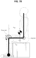
- FIG. 7B is a conceptual diagram showing torques at initial position.
- FIG. 9A is a conceptual diagram showing the tendency of assisting torque based on the location of point of action.
- FIG. 9B is a graph showing the result of subtracting a knee assisting torque by diagonal direction support and a knee torque by weight.
- a standing assistance apparatus 100 of the present disclosure includes a support part 10 , a saddle part 20 and a guide part 30 .
- the support part 10 is designed to support loads.
- FIG. 1 shows an example of the support part 10 placed in the up/down direction to support loads of a patient and other components connected to the support part 10 .
- the support part 10 needs to have a receiving space 13 in which a driving part 50 and a power transmission part 60 as described below may be installed, and to this end, the support part 10 is preferably hollow.
- the support part 10 may be formed in the shape of a long circular pipe, but is not limited thereto.
- the connecting frame 21 is coupled to the guide part 30 in a direction in which the connecting frame 21 intersects with the guide part 30 , and the rotation rod 23 is rotatably connected to the connecting frame 21 .
- the patient holding part 25 holds the patient in sitting condition, in guided condition from sitting condition to standing condition and in standing condition
- FIG. 3A shows an example in which the patient holding part 25 is installed in the rotation rod 23 at the lower end of the guide part 30 to hold the patient's back and waist.
- the linking part 27 links the ends of the rotation rod 23 so that the patient holding part 25 may hold the patient.
- the guide part 30 is coupled between the support part 10 and the saddle part 20 . Additionally, the length of the guide part 30 is adjustable so that the guide part 30 guides the standing of the patient from the sitting condition of the patient to the standing condition. As the guide part 30 is disposed in diagonal direction with respect to the support part 10 , the patient may be guided in diagonal direction by the guide part 30 when the patient sits on the saddle part 20 .
- the guide part 30 may include case 31 a , 31 b , shaft 33 a , 33 b and boss 35 .
- the case 31 a , 31 b has a shaft receiving part 31 c inside, and extends in the diagonal direction.
- the case 31 a , 31 b may be formed in the shape of a pipe into which the shaft 33 a , 33 b is inserted moveably relative to the case 31 a , 31 b , but is not limited thereto.
- the shaft 33 a , 33 b is inserted into the shaft receiving part 31 c moveably relative to the case 31 a , 31 b.
- the boss 35 is installed at the outer periphery of the shaft 33 a , 33 b to guide the movement of the shaft 33 a , 33 b , and locks the end of the shaft 33 a , 33 b to limit the movement of the shaft 33 a , 33 b . Additionally, the boss 35 locks the end of the shaft 33 a , 33 b to prevent the separation of the shaft 33 a , 33 b when the relative distance between the shaft 33 a , 33 b and the case 31 a , 31 b is large. For example, the boss 35 may be installed on one inner side of the case 31 a , 31 b.
- the shaft 33 a , 33 b when the patient is in sitting condition, the shaft 33 a , 33 b may be disposed at the maximum protruding location from the case 31 a , 31 b , and when the patient is in standing condition, the shaft 33 a , 33 b may be received in the case 31 a , 31 b to the maximum. In this way, the length of the guide part 30 may be adjusted.
- the guide part 30 may include two cases 31 a , 31 b and two shafts 33 a , 33 b , and its description is provided below.
- first case 31 a the case that is directly coupled to the support part 10
- second shaft 33 b the shaft that is directly connected to the saddle part
- second case 31 b the case that receives the second shaft 33 b will be referred to as a second case 31 b.
- the first case 31 a has a cutout part 31 a - 1 where a part of the first case 31 a is cut, and the second case 31 b makes a relative motion by guidance of the cutout part 31 a - 1 of the first case 31 a . Accordingly, the relative distance between the first and second cases 31 a , 31 b may be adjusted.
- the boss 35 may be each installed in between the first case 31 a and the first shaft 33 a and between the second case 31 b and the second shaft 33 b.
- a connecting plate 37 a , 37 b may be installed at two ends of the first shaft 33 a and the second case 31 b to connect them each other.
- the connecting plates 37 a , 37 b allow the first shaft 33 a and the second case 31 b to move relative to the first case 31 a together, and when the first shaft 33 a is inserted into the first case 31 a , the second case 31 b is allowed to move together by guidance along the cutout part 31 a - 1 of the first case 31 a .
- the first connecting plate 37 a has a hole to allow the second shaft 33 b to move
- the second connecting plate 37 b has a hole to allow the first shaft 33 a to move.
- the first and second connecting plates 37 a , 37 b has a hole to allow the second shaft 33 b and the first shaft 33 a to move respectively, and when the patient stands up, the first and second shafts 33 a , 33 b may be inserted into the first and second cases 31 a , 31 b respectively.
- the length of the guide part 30 may be adjusted, and the guide part 30 guides the standing from sitting condition of the patient to standing condition.
- the guide part 30 is connected to the power transmission part 60 that transmits power generated by the driving part 50 to transmit the power for length adjustment, and the driving part 50 and the power transmission part 60 will be described below.
- the standing assistance apparatus 100 of the present disclosure may further include a base frame 70 installed below the support part 10 to support the support part 10 .
- a knee support part 78 may be installed in the base frame 70 to support the patient's knees.
- the base frame 70 may include first and second members 75 a , 75 b.
- the first member 75 a is coupled to the bottom of the support part 10 and extends in a direction in which the first member 75 a intersects with the support part 10 , and includes a received guide part 75 a - 1 therein along the direction in which the first member 75 a extends.
- FIGS. 1, 5A and 5B show an example in which a coupling frame 71 is installed below the support part 10 , and the first member 75 a is each connected to two ends of the coupling frame 71 .
- the second member 75 b is inserted into and guided by the received guide part and moves relative to the first member 75 a .
- the knee support part 78 may be installed in the second member 75 b.
- FIG. 5A shows an example in which a connecting link 76 a is installed in the second member 75 b and the knee support part 78 is installed in the connecting link 76 a by a fixing part 76 b . Accordingly, the knee support part 78 may move together with the second member 75 b , and thus the location may be adjusted in consideration of the position or physical dimension of the patient.
- the base frame 70 may further include an elastic part 75 c , a ratchet gear 75 d and a stopper part 75 e.
- the elastic part 75 c is installed in the first member 75 a and elastically deforms between the first and second members 75 a , 75 b when the second member 75 b moves relative to the first member 75 a , so that an elastic force is provided to the knee support part 78 .
- the elastic part 75 c may be installed in the received guide part 75 a - 1 .
- the elastic part 75 c may be a spring.
- the ratchet gear 75 d may be installed at the end of the second member 75 b and placed along the direction in which the second member 75 b extends.
- FIGS. 5A and 5B show an example of the ratchet gear 75 d , and the teeth of the ratchet gear 75 d may include a slope part formed diagonally and a jaw part formed in perpendicular direction to the ground.
- the stopper part 75 e is installed in the first member 75 a to latch the ratchet gear 75 d to limit the movement of the knee support part 78 toward the support part 10 .
- the stopper part 75 e allows the movement to the left by the slope part of the ratchet gear 75 d , and limits the movement to the right by latching by the jaw part of the ratchet gear 75 d .
- the second member 75 b may move to the left with respect to the first member 75 a by the stopper part 75 e and the ratchet gear 75 d , and the movement to the right is limited.
- a plurality of castors 79 may be installed at the lower end of the base frame 70 , and the plurality of castors 79 allows the support part 10 and its connected elements to move.
- the standing assistance apparatus 100 of the present disclosure may further include the driving part 50 and the power transmission part 60 .
- the driving part 50 is installed in the support part 10 to generate driving power for allowing the patient to stand.
- the driving part 50 may include a gas cylinder 52 and a gas spring 56 .
- the gas cylinder 52 is installed in one direction within the support part 10 to generate the driving power.
- the gas cylinder 52 may generate a force of about 20 kgf.
- the gas spring 56 is installed in parallel with the gas cylinder 52 within the support part 10 to assist the generation of driving power.
- the gas spring 56 assists the driving power of the gas cylinder 52 to allow the gas cylinder 52 to generate a force of about 25 kgf.
- the driving part 50 may further include a guide rod 58 .
- the guide rod 58 is installed in parallel with the gas cylinder 52 within the support part 10 , and is supplied with the driving power and is guided by a guide hole of a fixed block together with the gas cylinder 52 .
- the fixed block is installed at the inner periphery of the support part 10 , and has the guide hole formed in one direction.
- the gas cylinder 52 and the gas spring 56 generate driving power in the up/down direction within the support part 10 , and the driving power is provided to the guide part 30 through the power transmission part 60 .
- the power transmission part 60 is connected between the driving part 50 and the guide part 30 , and transmits the driving power generated by the driving part 50 to the guide part 30 so that the length of the guide part 30 may be adjusted.
- the power transmission part 60 may include first to third pulleys 62 , 64 , 66 and a wire 68 .
- the first pulley 62 is configured to move using the driving power supplied from the driving part 50 .
- the first pulley 62 may be rotatably installed at the upper end of the driving part 50
- FIGS. 2A and 2B show an example in which a pulley housing 62 a is coupled to the upper end of the guide rod 58 , and the first pulley 62 is rotatably installed in the pulley housing 62 a .
- the first pulley 62 may move in the up/down direction within the support part 10 by the wire 68 as described below.
- FIG. 2A shows an example in which the first pulley 62 moves between the third pulley 66 and the fixed block 69 by the wire 68 .
- the first pulley 62 may be a moving pulley.
- the second and third pulleys 64 , 66 may be installed at adjacent ends of the support part 10 and the guide part 30 respectively.
- FIG. 2A shows an example of the second pulley 64 rotatably installed at the upper part of the support part 10 , but although not clearly shown, a second pulley housing may be fixed and installed at the upper part of the support part 10 , and the second pulley 64 may be rotatably coupled to the second pulley housing through a rotation axis.
- the third pulley 66 is rotatably installed in a pulley connection part 31 a - 1 at the end of the first case 31 a of the guide part 30 .
- the installation method of the second and third pulleys 64 , 66 is not limited thereto, and the second and third pulleys 64 , 66 may be installed in various ways to transmit the driving power generated by the driving part 50 to the guide part 30 .
- Each of the second and third pulleys 64 , 66 may be a fixed pulley.
- the wire 68 is installed in the first to third pulleys 62 , 64 , 66 . Additionally, one end of the wire 68 is fixed to the inner side of the support part 10 , and the other end is fixed to the other end of the guide part 30 .
- FIG. 2A shows an example in which one end of the wire 68 is fixed to the inner side of the support part 10 and is wound on the bottom of the first pulley 62 and parts of each of the third and second pulleys 66 , 64 , and the other end is fixed to the end of the second shaft 33 b of the guide part 30 .
- the patient may stand up with a force of 1 ⁇ 2 of the force required when the first to third pulleys 62 , 64 , 66 are not installed and only the wire 68 is connected. Additionally, it is possible to offer double strokes for the gas cylinder 52 and the gas spring 56 , thereby reducing the problem with bulking in terms of weight and size.
- an angle adjustment part 90 may be installed at the upper part of the support part 10 , and the angle adjustment part 90 may be disposed between the support part 10 and the first case 31 a .
- the angle adjustment part 90 has a plurality of holes that is spaced apart from each other in circumferential direction with respect to a point, and a protrusion is formed at the outer periphery of the first case 31 a such that the protrusion may be inserted into the holes of the angle adjustment part 90 .
- the guide part 30 may pivot around the support part 10 , the guide part 30 may be fixed to the support part 10 when the protrusion of the first case 31 a is inserted into one of the holes of the angle adjustment part 90 , thereby adjusting the angle between the support part 10 and the guide part 30 .
- the guide part 30 is disposed nearly in parallel with the support part 10 , forming a structure that is easy to receive the standing assistance apparatus 100 of the present disclosure.
- an example is shown in which the protrusion of the first guide frame 31 is inserted into the other hole within the angle adjustment part 90 , forming an angle of about 45° between the guide part 30 and the support part 10 .
- the angle between the support part 10 and the guide part 30 may be adjusted by the angle adjustment part 90 , thereby minimizing the volume of the standing assistance apparatus 100 when receiving the standing assistance apparatus 100 , and guiding the standing while adjusting the standing angle to suit the patient's physical dimensions when using the standing assistance apparatus 100 .
- the standing assistance apparatus 100 of the present disclosure may further include a handle part 80 .
- the handle part 80 may be installed in the support part 10 , and may have a rod shape to easily guide the standing of the patient.
- FIG. 1 shows an example of the handle part 80 formed in the shape of a rod that is bent multiple times. It is desirable to adjust the height at which the handle part 80 is installed in the support part 10 and the distance from the handle part 80 to the patient, taking into account the patient's physical condition.
- a manipulation part 83 may be installed in the handle part 80 to manipulate the stopper part 75 e of the base frame 70 .
- the manipulation part 83 moves the stopper part 75 e to disengage from the ratchet gear 75 d.
- FIG. 6A is a conceptual diagram showing forces acting on a human body in a vertical direction standing assistance method
- FIG. 6B is a conceptual diagram showing forces acting on a human body in a diagonal direction standing assistance method.
- the present disclosure is directed toward a diagonal direction support assisting method, and obtained the conclusion that as a result of kinematics simulation and direct experiments, the diagonal direction support assisting method may assist the user with a smaller force than the vertical standing assistance method. Additionally, the support for raising up is reduced and the sitting restoration force required is small, so the old person may restore by his/her weight.
- the support is about 55 kgf and the sitting restoration force required is about 55 kgf, but when the diagonal direction support assisting method is used, the sitting restoration force is reduced to 27 kgf which is nearly half.
- FIG. 7A is a conceptual diagram showing forces and torques in vertical and diagonal directions at an arbitrary standing position
- FIG. 7B is a conceptual diagram showing torques at initial position.
- Fv denotes the vertical direction spring force for standing
- F D denotes the diagonal direction spring force for standing
- ⁇ i denotes the torque at the initial position
- ⁇ denotes the torque at an arbitrary standing position
- r m denotes the distance between the knee joint and the center of gravity at an arbitrary standing position
- r f denotes the distance between the knee joint and the point of action at an arbitrary standing position.
- FIG. 8 is a graph of vertical direction standing and diagonal direction standing.
- the left graph of FIG. 8 about vertical direction standing shows the knee joint torque changes occurring by Fv with the knee joint angle changes, in which the torque by the spring force is greater than the torque by the weight (torque at the full range of angles), and it is difficult to restore the standing assistance apparatus to the initial position.
- the right graph of FIG. 8 about diagonal direction standing shows the knee joint torque changes occurring by Fd with the knee joint angle changes, in which the standing assistance torque is greater than the torque by the weight (angle after the point of intersection), and a force is necessary at the initial position, but it is easy to restore to the initial position.
- the blue line indicates the torque needed for the patient/old person to stand.
- the amounts of torque compensation with the knee joint angle changes of F.B.D human body model are compared at two viewpoints of vertical/diagonal direction support.
- the vertical direction support Fv the support having the same tendency with the angle changes of the knees is produced.
- the vertical direction support is 1.4 Fv
- significant assistance is possible when the torque generated by the support is greater than the torque generated by the weight.
- manual standing assistance devices because an electric motor is not used, there are difficulties in having to restore the standing assistance device to the initial position directly by hands.
- the torque by the support is greater than the torque by the weight. It is possible to produce the support of higher efficiency with a force for standing that is smaller about 2-3 times. However, before the point of intersection, it is necessary to generate a small force by the muscular strength of the patient. However, in the case of typical paraplegic patients or old people, the lower body muscular strength is insufficient, but the muscular strength in arms is not lost. Additionally, in an attempt to stand, only if an assistant pulls slightly, it will work as a trigger definitely to allow them to stand.
- FIG. 9A is a conceptual diagram showing the tendency of assisting torque based on the location of point of action
- FIG. 9B is a graph showing the result of subtracting a knee assisting torque by diagonal direction support and a knee torque by weight.
- the positive direction indicates the assisted torque
- the negative direction indicates the torque the user is required to apply directly.
- the torque that may assist decreases.
- the torque that may assist increases.
- the assisting torque for the knees increases.
- a gain torque generated by a difference in the location of the point of action will be applied to the hip joint. This indicates the need for methodology that selects a suitable location of point of action for the level of muscular strength of the patient.
- the standing assistance apparatus of the present disclosure assists the patient or old person with a small force because the guide part is disposed in diagonal direction and the shaft is inserted into the case and makes a relative motion.
- the standing assistance apparatus of the present disclosure may assist patients or weak and old people to stand without using an electric power source by generating driving power by the gas spring and the gas cylinder and transmitting the generated driving power to the guide part through the pulley and the wire.
- the standing assistance apparatus 100 described hereinabove is not limited to the configuration and method of the embodiments described in the foregoing, and some or all the embodiments may be selectively combined to make various modifications to the embodiments.
Abstract
Description
Claims (12)
Applications Claiming Priority (2)
| Application Number | Priority Date | Filing Date | Title |
|---|---|---|---|
| KR10-2017-0146659 | 2017-11-06 | ||
| KR1020170146659A KR102088420B1 (en) | 2017-11-06 | 2017-11-06 | Standing assistance apparatus |
Publications (2)
| Publication Number | Publication Date |
|---|---|
| US20190133859A1 US20190133859A1 (en) | 2019-05-09 |
| US11219568B2 true US11219568B2 (en) | 2022-01-11 |
Family
ID=66326499
Family Applications (1)
| Application Number | Title | Priority Date | Filing Date |
|---|---|---|---|
| US16/166,158 Active 2040-08-15 US11219568B2 (en) | 2017-11-06 | 2018-10-22 | Standing assistance apparatus |
Country Status (2)
| Country | Link |
|---|---|
| US (1) | US11219568B2 (en) |
| KR (1) | KR102088420B1 (en) |
Families Citing this family (1)
| Publication number | Priority date | Publication date | Assignee | Title |
|---|---|---|---|---|
| CN112168560B (en) * | 2020-11-04 | 2022-10-21 | 漯河医学高等专科学校 | Auxiliary rising equipment for clinical nursing and working method thereof |
Citations (15)
| Publication number | Priority date | Publication date | Assignee | Title |
|---|---|---|---|---|
| JPH069591B2 (en) | 1991-03-14 | 1994-02-09 | 労働福祉事業団 | Standing auxiliary device |
| JPH09570A (en) | 1994-10-14 | 1997-01-07 | Funaki Gishi:Kk | Posture conversion device and posture conversion method |
| JPH09299414A (en) | 1996-05-20 | 1997-11-25 | San Le-Mu:Kk | Human body hoisting apparatus for nursing and nursing method using the same |
| JPH11188063A (en) | 1997-12-26 | 1999-07-13 | Takahiro Hayakawa | Movable lift for nursing |
| US6539569B2 (en) | 2000-03-02 | 2003-04-01 | O'connell Timothy B. | Motorized patient transfer system for beds |
| JP2003305096A (en) | 2002-04-15 | 2003-10-28 | Taichi:Kk | Standing-up assisting device provided with walking assisting function |
| EP1595519A1 (en) | 2004-05-12 | 2005-11-16 | Exodus Holding B.V. | Lift device |
| US20050268397A1 (en) * | 2004-06-03 | 2005-12-08 | Avinoam Nativ | Apparatus for assisting a person to stand and walk |
| US20090188038A1 (en) * | 2008-01-28 | 2009-07-30 | Terry Raney | Storable dual action hydraulic lifting device |
| US20120280464A1 (en) | 2008-10-27 | 2012-11-08 | Nelson Richard L | Adjustable load-bearing wheels and kits for patient lifters |
| KR101320043B1 (en) | 2011-11-16 | 2013-10-18 | 한국과학기술원 | Walking Aided Apparatus of lifting type |
| EP2853249A1 (en) | 2013-09-27 | 2015-04-01 | Remco Bos | Walker assembly and method of use to assist a seated person to rise to a standing position |
| US20160120722A1 (en) * | 2012-12-03 | 2016-05-05 | Peter A. Mueller | Lift |
| US20160166451A1 (en) * | 2014-10-20 | 2016-06-16 | Daniel Tekulve | Portable rehab station with standing assist |
| US20170156959A1 (en) * | 2015-12-04 | 2017-06-08 | Robert Domenick | Rotational/Translational Transfer Lift |
Family Cites Families (1)
| Publication number | Priority date | Publication date | Assignee | Title |
|---|---|---|---|---|
| WO2011036999A1 (en) * | 2009-09-24 | 2011-03-31 | Semiconductor Energy Laboratory Co., Ltd. | Oxide semiconductor film and semiconductor device |
-
2017
- 2017-11-06 KR KR1020170146659A patent/KR102088420B1/en active IP Right Grant
-
2018
- 2018-10-22 US US16/166,158 patent/US11219568B2/en active Active
Patent Citations (16)
| Publication number | Priority date | Publication date | Assignee | Title |
|---|---|---|---|---|
| JPH069591B2 (en) | 1991-03-14 | 1994-02-09 | 労働福祉事業団 | Standing auxiliary device |
| JPH09570A (en) | 1994-10-14 | 1997-01-07 | Funaki Gishi:Kk | Posture conversion device and posture conversion method |
| JPH09299414A (en) | 1996-05-20 | 1997-11-25 | San Le-Mu:Kk | Human body hoisting apparatus for nursing and nursing method using the same |
| JPH11188063A (en) | 1997-12-26 | 1999-07-13 | Takahiro Hayakawa | Movable lift for nursing |
| US6539569B2 (en) | 2000-03-02 | 2003-04-01 | O'connell Timothy B. | Motorized patient transfer system for beds |
| JP2003305096A (en) | 2002-04-15 | 2003-10-28 | Taichi:Kk | Standing-up assisting device provided with walking assisting function |
| EP1595519A1 (en) | 2004-05-12 | 2005-11-16 | Exodus Holding B.V. | Lift device |
| US20050268397A1 (en) * | 2004-06-03 | 2005-12-08 | Avinoam Nativ | Apparatus for assisting a person to stand and walk |
| US20090188038A1 (en) * | 2008-01-28 | 2009-07-30 | Terry Raney | Storable dual action hydraulic lifting device |
| US20120280464A1 (en) | 2008-10-27 | 2012-11-08 | Nelson Richard L | Adjustable load-bearing wheels and kits for patient lifters |
| WO2010085332A2 (en) | 2009-01-22 | 2010-07-29 | Terry Raney | Storable dual action hydraulic lifting device |
| KR101320043B1 (en) | 2011-11-16 | 2013-10-18 | 한국과학기술원 | Walking Aided Apparatus of lifting type |
| US20160120722A1 (en) * | 2012-12-03 | 2016-05-05 | Peter A. Mueller | Lift |
| EP2853249A1 (en) | 2013-09-27 | 2015-04-01 | Remco Bos | Walker assembly and method of use to assist a seated person to rise to a standing position |
| US20160166451A1 (en) * | 2014-10-20 | 2016-06-16 | Daniel Tekulve | Portable rehab station with standing assist |
| US20170156959A1 (en) * | 2015-12-04 | 2017-06-08 | Robert Domenick | Rotational/Translational Transfer Lift |
Non-Patent Citations (3)
| Title |
|---|
| Korean Notice of Allowance for KR Application No. 10-2017-0146659 dated Feb. 25, 2020. |
| Raising support product "Roll On" of Liko Company (http://www.liko.com/ie/Ireland/Videos/Video-Archive/RollOn1/RollOn-Transfer-between-bed-and-wheelchair/), Oct. 25, 2016. |
| Seung-Won Kim et al., "Design and Experiment of a Passive Sit-to-Stand and Walking (STSW) Assistance Device for the elderly", IEEE Engineering in Medicine and Biology Society, 2018, pp. 1781-1784. |
Also Published As
| Publication number | Publication date |
|---|---|
| KR102088420B1 (en) | 2020-04-23 |
| US20190133859A1 (en) | 2019-05-09 |
| KR20190051239A (en) | 2019-05-15 |
Similar Documents
| Publication | Publication Date | Title |
|---|---|---|
| US11432988B2 (en) | Actuation system for hip orthosis | |
| TWI700081B (en) | Stand up aid | |
| US20110251533A1 (en) | Wearable robotic system for rehabilitation training of the upper limbs | |
| US9393172B2 (en) | Spinal traction machine and methods | |
| WO2020222938A1 (en) | Gravity compensation mechanisms and methods | |
| CN109011404B (en) | Shoulder joint rehabilitation training medical equipment | |
| CN212940468U (en) | Rigid-flexible coupling wearable walking-aid exoskeleton system | |
| JP2012115569A (en) | Upper limb rehabilitation device | |
| US11219568B2 (en) | Standing assistance apparatus | |
| Bian et al. | Mechanical design of EFW Exo II: A hybrid exoskeleton for elbow-forearm-wrist rehabilitation | |
| ITUA20163483A1 (en) | ROBOTIC DEVICE FOR THE VERTICALIZATION AND MOBILITY OF SERIOUS DISABLED MOTORS | |
| JP6655092B2 (en) | Method and apparatus for waking a lying person | |
| KR20190015122A (en) | Weight training device for disabled people with spinal cord injury | |
| CN211050095U (en) | Flexible lower limb rehabilitation training mechanism | |
| CN109011403B (en) | Medical shoulder joint rehabilitation training device | |
| CN110613584A (en) | Flexible lower limb rehabilitation training mechanism | |
| US11771606B2 (en) | Ambulatory assist device | |
| US20190274862A1 (en) | System and Method for Reducing Forces Acting on a Spinal Column | |
| TWM566066U (en) | Assistive devices for getting up | |
| CN112296984B (en) | Inhaul cable driving mechanism and portable power assisting device thereof | |
| KR102022569B1 (en) | Weight training device for disabled people with spinal cord injury | |
| KR102602688B1 (en) | Device for hand rehabilitation | |
| CN109044730B (en) | Vertical and horizontal dual-purpose shoulder joint rehabilitation training medical robot for patient | |
| KR100723297B1 (en) | A whole body exercise device | |
| CN215021726U (en) | A unconscious patient limbs rehabilitation device for intensive care unit nursing |
Legal Events
| Date | Code | Title | Description |
|---|---|---|---|
| FEPP | Fee payment procedure |
Free format text: ENTITY STATUS SET TO UNDISCOUNTED (ORIGINAL EVENT CODE: BIG.); ENTITY STATUS OF PATENT OWNER: SMALL ENTITY |
|
| AS | Assignment |
Owner name: KOREA INSTITUTE OF SCIENCE AND TECHNOLOGY, KOREA, REPUBLIC OF Free format text: ASSIGNMENT OF ASSIGNORS INTEREST;ASSIGNORS:YUH, JUNKU;KANG, SUNG CHUL;LEE, WOOSUB;AND OTHERS;REEL/FRAME:047285/0438 Effective date: 20181015 Owner name: KOREA INSTITUTE OF SCIENCE AND TECHNOLOGY, KOREA, Free format text: ASSIGNMENT OF ASSIGNORS INTEREST;ASSIGNORS:YUH, JUNKU;KANG, SUNG CHUL;LEE, WOOSUB;AND OTHERS;REEL/FRAME:047285/0438 Effective date: 20181015 |
|
| FEPP | Fee payment procedure |
Free format text: ENTITY STATUS SET TO SMALL (ORIGINAL EVENT CODE: SMAL); ENTITY STATUS OF PATENT OWNER: SMALL ENTITY |
|
| STPP | Information on status: patent application and granting procedure in general |
Free format text: DOCKETED NEW CASE - READY FOR EXAMINATION |
|
| STPP | Information on status: patent application and granting procedure in general |
Free format text: NON FINAL ACTION MAILED |
|
| STPP | Information on status: patent application and granting procedure in general |
Free format text: RESPONSE TO NON-FINAL OFFICE ACTION ENTERED AND FORWARDED TO EXAMINER |
|
| STPP | Information on status: patent application and granting procedure in general |
Free format text: NOTICE OF ALLOWANCE MAILED -- APPLICATION RECEIVED IN OFFICE OF PUBLICATIONS |
|
| STPP | Information on status: patent application and granting procedure in general |
Free format text: PUBLICATIONS -- ISSUE FEE PAYMENT VERIFIED |
|
| STCF | Information on status: patent grant |
Free format text: PATENTED CASE |