US11219496B2 - Surgical tool, medical treatment instrument, and surgical system - Google Patents
Surgical tool, medical treatment instrument, and surgical system Download PDFInfo
- Publication number
- US11219496B2 US11219496B2 US16/262,949 US201916262949A US11219496B2 US 11219496 B2 US11219496 B2 US 11219496B2 US 201916262949 A US201916262949 A US 201916262949A US 11219496 B2 US11219496 B2 US 11219496B2
- Authority
- US
- United States
- Prior art keywords
- pulley
- elongate element
- guide pulley
- shaft
- proximal end
- Prior art date
- Legal status (The legal status is an assumption and is not a legal conclusion. Google has not performed a legal analysis and makes no representation as to the accuracy of the status listed.)
- Active, expires
Links
Images


Classifications
-
- A—HUMAN NECESSITIES
- A61—MEDICAL OR VETERINARY SCIENCE; HYGIENE
- A61B—DIAGNOSIS; SURGERY; IDENTIFICATION
- A61B34/00—Computer-aided surgery; Manipulators or robots specially adapted for use in surgery
- A61B34/70—Manipulators specially adapted for use in surgery
- A61B34/71—Manipulators operated by drive cable mechanisms
-
- A—HUMAN NECESSITIES
- A61—MEDICAL OR VETERINARY SCIENCE; HYGIENE
- A61B—DIAGNOSIS; SURGERY; IDENTIFICATION
- A61B34/00—Computer-aided surgery; Manipulators or robots specially adapted for use in surgery
- A61B34/30—Surgical robots
-
- A—HUMAN NECESSITIES
- A61—MEDICAL OR VETERINARY SCIENCE; HYGIENE
- A61B—DIAGNOSIS; SURGERY; IDENTIFICATION
- A61B17/00—Surgical instruments, devices or methods
- A61B17/28—Surgical forceps
- A61B17/29—Forceps for use in minimally invasive surgery
-
- A—HUMAN NECESSITIES
- A61—MEDICAL OR VETERINARY SCIENCE; HYGIENE
- A61B—DIAGNOSIS; SURGERY; IDENTIFICATION
- A61B34/00—Computer-aided surgery; Manipulators or robots specially adapted for use in surgery
- A61B34/30—Surgical robots
- A61B34/35—Surgical robots for telesurgery
-
- A—HUMAN NECESSITIES
- A61—MEDICAL OR VETERINARY SCIENCE; HYGIENE
- A61B—DIAGNOSIS; SURGERY; IDENTIFICATION
- A61B34/00—Computer-aided surgery; Manipulators or robots specially adapted for use in surgery
- A61B34/30—Surgical robots
- A61B34/37—Leader-follower robots
-
- A—HUMAN NECESSITIES
- A61—MEDICAL OR VETERINARY SCIENCE; HYGIENE
- A61B—DIAGNOSIS; SURGERY; IDENTIFICATION
- A61B17/00—Surgical instruments, devices or methods
- A61B17/00234—Surgical instruments, devices or methods for minimally invasive surgery
- A61B2017/00292—Surgical instruments, devices or methods for minimally invasive surgery mounted on or guided by flexible, e.g. catheter-like, means
- A61B2017/003—Steerable
- A61B2017/00305—Constructional details of the flexible means
- A61B2017/00314—Separate linked members
-
- A—HUMAN NECESSITIES
- A61—MEDICAL OR VETERINARY SCIENCE; HYGIENE
- A61B—DIAGNOSIS; SURGERY; IDENTIFICATION
- A61B17/00—Surgical instruments, devices or methods
- A61B17/00234—Surgical instruments, devices or methods for minimally invasive surgery
- A61B2017/00292—Surgical instruments, devices or methods for minimally invasive surgery mounted on or guided by flexible, e.g. catheter-like, means
- A61B2017/003—Steerable
- A61B2017/00318—Steering mechanisms
- A61B2017/00323—Cables or rods
-
- A—HUMAN NECESSITIES
- A61—MEDICAL OR VETERINARY SCIENCE; HYGIENE
- A61B—DIAGNOSIS; SURGERY; IDENTIFICATION
- A61B17/00—Surgical instruments, devices or methods
- A61B17/28—Surgical forceps
- A61B17/29—Forceps for use in minimally invasive surgery
- A61B2017/2901—Details of shaft
- A61B2017/2905—Details of shaft flexible
-
- A—HUMAN NECESSITIES
- A61—MEDICAL OR VETERINARY SCIENCE; HYGIENE
- A61B—DIAGNOSIS; SURGERY; IDENTIFICATION
- A61B17/00—Surgical instruments, devices or methods
- A61B17/28—Surgical forceps
- A61B17/29—Forceps for use in minimally invasive surgery
- A61B2017/2901—Details of shaft
- A61B2017/2906—Multiple forceps
-
- A—HUMAN NECESSITIES
- A61—MEDICAL OR VETERINARY SCIENCE; HYGIENE
- A61B—DIAGNOSIS; SURGERY; IDENTIFICATION
- A61B17/00—Surgical instruments, devices or methods
- A61B17/34—Trocars; Puncturing needles
- A61B17/3417—Details of tips or shafts, e.g. grooves, expandable, bendable; Multiple coaxial sliding cannulas, e.g. for dilating
- A61B17/3421—Cannulas
- A61B2017/3445—Cannulas used as instrument channel for multiple instruments
- A61B2017/3447—Linked multiple cannulas
-
- A—HUMAN NECESSITIES
- A61—MEDICAL OR VETERINARY SCIENCE; HYGIENE
- A61B—DIAGNOSIS; SURGERY; IDENTIFICATION
- A61B34/00—Computer-aided surgery; Manipulators or robots specially adapted for use in surgery
- A61B34/30—Surgical robots
- A61B2034/302—Surgical robots specifically adapted for manipulations within body cavities, e.g. within abdominal or thoracic cavities
-
- A—HUMAN NECESSITIES
- A61—MEDICAL OR VETERINARY SCIENCE; HYGIENE
- A61B—DIAGNOSIS; SURGERY; IDENTIFICATION
- A61B34/00—Computer-aided surgery; Manipulators or robots specially adapted for use in surgery
- A61B34/30—Surgical robots
- A61B2034/305—Details of wrist mechanisms at distal ends of robotic arms
-
- A—HUMAN NECESSITIES
- A61—MEDICAL OR VETERINARY SCIENCE; HYGIENE
- A61B—DIAGNOSIS; SURGERY; IDENTIFICATION
- A61B34/00—Computer-aided surgery; Manipulators or robots specially adapted for use in surgery
- A61B34/70—Manipulators specially adapted for use in surgery
- A61B34/71—Manipulators operated by drive cable mechanisms
- A61B2034/715—Cable tensioning mechanisms for removing slack
Definitions
- the disclosure relates to tension adjusting mechanisms for elongate elements that drive end effectors used for surgical tools and other purposes, and interfaces and driving mechanisms including the tension adjusting mechanisms.
- robotic surgical systems have been used in fields such as endoscopic surgery.
- a medical treatment instrument used for a robotic surgical system for example, elongate elements such as wires are engaged with end effectors with jaws and the like.
- a driving mechanism including gears is driven, the elongate elements are pulled in or fed out, driving the end effectors.
- Such elongate elements may get loose or slack, for example, for the reason that tension is exerted on them for a long time.
- medical treatment instruments have been developed in which the tensions of elongate elements can be adjusted using springs or the like.
- Patent Document 1 published Japanese Translation of PCT International Patent Application No. 2012-504016
- Patent Document 2 Japanese Patent Application Publication No. 2013-103074 disclose medical treatment instruments in which the tensions of the elongate elements are adjusted by springs or the like via which parts of the elongate elements are attached to the housing.
- Patent Document 3 Japanese Patent Application Publication No. 2016-016242 discloses a medical treatment instrument in which the tensions of elongate elements are adjusted in such a way that two pulleys, on which the elongate elements are wound, are coupled to each other via springs or the like.
- An object of an embodiment of the disclosure is to provide a tension adjusting mechanism that is small but capable of adjusting the tension of an elongate element for driving an end effector, and an interface and driving mechanism including the tension adjusting mechanisms.
- a surgical tool may include: an end effector; a elongate element that drives the end effector; a hollow shaft that includes a proximal end portion and a distal end portion which is coupled to the end effector; a driving member which the elongate element led via the shaft is wound on; a guide pulley that is disposed between the proximal end portion of the shaft and the driving member and guides the elongate element; and a tension pulley that is disposed between the proximal end portion of the shaft and the guide pulley and biases the elongate element.
- a medical treatment instrument may include: surgical tools each including an end effector and a flexible shaft; driving devices to which the surgical tools are attached respectively; and an outer tube that holds the shafts of the surgical tools.
- Each of the surgical tools includes: the end effector; a elongate element that drives the end effector; the shaft that is hollow and includes a proximal end portion and a distal end portion which is coupled to the end effector; a driving member which the elongate element led via the shaft is wound on; a guide pulley that is disposed between the proximal end portion of the shaft and the driving member and guides the elongate element; and a tension pulley that is disposed between the proximal end portion of the shaft and the guide pulley and biases the elongate element.
- a surgical system may include: surgical tools each including an end effector and a flexible shaft; driving devices to which the surgical tools are attached respectively; an outer tube that holds the shafts of the surgical tools; and a supporting device including holding portions that hold the respective driving devices and a grasping portion that grasps the outer tube.
- Each of the surgical tools includes: the end effector; a elongate element that drives the end effector; the shaft that is hollow and includes a proximal end portion and a distal end portion which is coupled to the end effector; a driving member which the elongate element led via the shaft is wound on; a guide pulley that is disposed between the proximal end portion of the shaft and the driving member and guides the elongate element; and a tension pulley that is disposed between the proximal end portion of the shaft and the guide pulley and biases the elongate element.
- FIG. 1 is a diagram illustrating a view of the structure of a surgical system according to one or more embodiments
- FIG. 2 is a diagram illustrating a perspective view of the structure of a medical treatment instrument according to one or more embodiments
- FIG. 3 is a diagram illustrating a perspective view of guide tubes inserted in a bundling tube
- FIG. 4 is a diagram illustrating a cross-sectional perspective view taken along line IV-IV in FIG. 3 ;
- FIG. 5 is a diagram illustrating a perspective view of the structure of a guide tube according to one or more embodiments
- FIG. 6 is a diagram illustrating a cross-sectional view taken along line VI-VI in FIG. 5 ;
- FIG. 7 is a diagram illustrating a diagram illustrating an outline structure of a surgical tool according to one or more embodiments.
- FIG. 8 is a diagram illustrating a view of the structure of a surgical-tool driving mechanism, such as is illustrated in FIG. 7 , with an interface separated;
- FIG. 9 is a diagram illustrating a view of the structure of a surgical-tool driving mechanism, such as is illustrated in FIG. 7 , with the interface attached;
- FIG. 10A is a diagram illustrating a view of the structure of a distal end portion of a surgical tool, such as is illustrated in FIG. 7 ;
- FIG. 10B is a diagram illustrating a view of the structure of a distal end portion of a surgical tool, such as is illustrated in FIG. 7 ;
- FIG. 10C is a diagram illustrating a view of the structure of a distal end portion of a surgical tool, such as is illustrated in FIG. 7 ;
- FIG. 11 is a diagram illustrating a view of the structure of a wrist portion, such as is illustrated in FIG. 10A ;
- FIG. 12 is a diagram illustrating a perspective view of the structure of the interface in the surgical-tool driving mechanism according to one or more embodiments
- FIG. 13 is a diagram illustrating a plan view of a structure of an interface, such as is illustrated in FIG. 12 ;
- FIG. 14 is a diagram illustrating a side view of the structure of an interface, such as is illustrated in FIG. 12 .
- FIG. 1 is a diagram illustrating the structure of a surgical system according to one or more embodiments.
- the surgical system 201 includes a medical treatment instrument 101 , controller 4 , and operation unit 5 .
- a surgeon W operates the medical treatment instrument 101 remotely to perform, for example, an endoscopic surgery.
- the medical treatment instrument 101 includes, for example, one or more surgical tools 1 , one or more endoscopes 8 , one or more guide tubes 11 into which distal ends of the surgical tools 1 and the endoscopes 8 are inserted, and a bundling tube 12 into which the one or more guide tubes 11 are inserted.
- the surgical tools 1 and the endoscopes 8 are supported by, for example, support tables 6 attached to a treatment table 7 .
- the surgical tools 1 , endoscopes 8 , guide tubes 11 , and operation unit 5 are electrically connected to the controller 4 .
- the operation unit 5 When the operation unit 5 is operated by the surgeon W, the operation unit 5 gives operation instructions to the surgical tools 1 , the endoscopes 8 and the guide tubes 11 via the controller 4 . This allows the surgeon W to remotely operate the surgical tools 1 , the endoscopes 8 , and the guide tubes 11 .
- FIG. 2 is a perspective view of the structure of the medical treatment instrument according to one or more embodiments.
- FIG. 2 illustrates the medical treatment instrument 101 part of which is inside the body of the patient but is seen through the body.
- the body surface of the patient is indicated by the dashed double-dotted lines, and an incised portion X formed in the body surface of the patient is indicated by the continuous line.
- the surgical tool 1 has a flexible shaft 2 in an elongated shape and a distal end portion 20 deposed at the distal end of the flexible shaft 2 .
- the distal end portion 20 and part of the flexible shaft 2 pass through the guide tube 11 and are exposed from the guide tube 11 .
- the endoscope 8 has a flexible shaft 2 in an elongated shape and a camera 81 disposed at the distal end of the flexible shaft 2 .
- the camera 81 and part of the flexible shaft 2 pass through the guide tube 11 and is exposed from the guide tube 11 .
- the guide tube 11 is made of, for example, soft plastic, such as polypropylene and vinyl chloride.
- the guide tube 11 has a not-illustrated wire member and a guide-tube-bending adjustment mechanism 103 that operates the wire member.
- the guide-tube-bending adjustment mechanism 103 is, for example, a mechanism that adjusts manually the pulling length of the wire member, also fixes the wire member by screwing so that the wire member does not move, and electrically adjusts the pulling length of the wire member by using a not-illustrated motor and gears with which the wire member is engaged.
- the guide-tube-bending adjustment mechanism 103 in this way, adjusts the pulling length of the wire member to bend a bending portion 31 of the guide tube 11 .
- the bundling tube 12 is made of, for example, soft plastic, such as polypropylene or vinyl chloride.
- the bundling tube 12 is flexible and has a tubular shape the inner diameter of which is larger than the outer diameter of the guide tube 11 .
- the bundling tube 12 is inserted through an incised portion X formed in the body surface of the patient into the body cavity.
- the bundling tube 12 may be inserted through a natural hole, such as the oral cavity, into the body of the patient, instead of through the incised portion X.
- the medical treatment instrument 101 may be used not only for laparoscopic surgeries but also for natural orifice transluminal endoscopic surgeries.
- the bundling tube 12 is grasped at the outer wall, for example, at the proximal end thereof, in other words, on the side which is not inserted into the body surface, by a grasping mechanism 102 , so that the position and orientation of the bundling tube 12 is fixed.
- the bundling tube 12 is inserted into the body cavity, for example, through an incised portion X formed in the body surface of the patient, it is more difficult to fix the position and orientation of the bundling tube 12 than in the case where the bundling tube 12 is inserted through a natural hole, such as the oral cavity.
- the grasping mechanism 102 for grasping the bundling tube 12 as above is especially useful in the case of grasping a medical treatment instrument used for a laparoscopic surgery.
- FIG. 3 is a perspective view of the guide tubes passing through the inside of the bundling tube.
- FIG. 4 is a cross-sectional perspective view taken along line IV-IV in FIG. 3 .
- the bundling tube 12 has one or more guides 21 that guide insertion of the guide tubes 11 .
- the guides 21 for example, are dovetail grooves formed on the inner wall of the bundling tube 12 and extending in the axial direction of the bundling tube 12 .
- each guide 21 has an approximately trapezoidal cross-sectional shape the width of which increases gradually from the inner circumferential surface toward the outer circumferential surface of the bundling tube 12 .
- the bundling tube 12 is flexible and can be bent at an appropriate angle to be inserted into the body cavity.
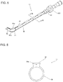
- FIG. 5 is a perspective view of the structure of a guide tube according to one or more embodiments.
- the guide tube 11 includes a flexible sleeve 30 , bending portion 31 , guide-tube distal end portion 32 , and guide-tube proximal end portion 33 .
- the guide tube 11 also has engaging portions 34 formed intermittently on the outer peripheral surface of the sleeve 30 and extending in the axial direction of the guide tube 11 .
- FIG. 6 is a cross-sectional view taken along line VI-VI in FIG. 5 .
- the engaging portion 34 is projected from the outer peripheral surface of the guide tube 11 and, for example, has an approximately trapezoidal cross-sectional shape the width of which gradually increases as the engaging portion 34 extends outwardly in the radial direction of the guide tube 11 .
- the engaging portions 34 are formed intermittently in the axial direction of the guide tube 11 as described above, the guide tube 11 can be easily inserted or removed from the bundling tube 12 even when the bundling tube 12 is bent. Note that the engaging portion 34 can be formed continuously in the axial direction of the sleeve 30 .
- the guide tube 11 has wire members 51 a and 51 b as illustrated in FIG. 5 as operating elements for operating the guide tube 11 .
- the wire member 51 a passes through the insides of the engaging portions 34 , and the first end side of the wire member 51 a is fixed to the guide-tube distal end portion 32 .
- the wire member 51 b passes through the inside of the sleeve 30 , and the first end side of the wire member 51 b is fixed to the guide-tube distal end portion 32 . Then, the guide-tube-bending adjustment mechanism 103 pulls in or feeds out the second end side of the wire member 51 a or the second end side of the wire member 51 b to bend the bending portion 31 .
- the bundling tube 12 does not need to have the guides 21 as described above, and the guide tube 11 does not need to have the engaging portions 34 as described above.
- the guide tube 11 may have, for example, rods, flat plates, or the combination of rods and flat plates that are connected to be bendable, instead of the wire members 51 a and 51 b.
- the wire member 51 a may be combined with rods and flat plates.
- the part passing through the engaging portions 34 may be a wire member 51 a and the exposed part connecting the engaging portion 34 and the guide-tube distal end portion 32 may be rods connected to be bendable.
- FIG. 7 is a diagram illustrating an outline structure of the surgical tool according to one or more embodiments.
- the surgical tool 1 has the distal end portion 20 , the flexible shaft 2 , and a surgical-tool driving mechanism 27 .
- the distal end portion 20 has an end effector 22 , such as grasping forceps, and a multi-articulated portion 24 .
- the end effector 22 has a first jaw 22 a , second jaw 22 b , and wrist portion 23 .
- the multi-articulated portion 24 has a first multi-articulated portion 24 a and a second multi-articulated portion 24 b.
- end effector 22 is not limited to the grasping forceps but may be a scalpel or a hook.
- first multi-articulated portion 24 a To each of the first jaw 22 a , second jaw 22 b , wrist portion 23 , first multi-articulated portion 24 a , and second multi-articulated portion 24 b is fixed an elongate element, such as a wire or a cable, described later.
- the flexible shaft 2 has a proximal end portion 2 a at the opposite end from the distal end portion 20 side end.
- the proximal end portion 2 a is coupled to the surgical-tool driving mechanism 27 so that the flexible shaft 2 itself is rotatable.
- the wrist portion 23 has a shape extending in a specific direction. Specifically, the wrist portion 23 has the first jaw 22 a and second jaw 22 b coupled to the first end in the longitudinal direction of the wrist portion 23 itself and the multi-articulated portion 24 coupled at its second end.
- the wrist portion 23 is rotatable on the distal end axis Z 1 extending in the longitudinal direction of the wrist portion 23 itself.
- FIG. 8 is a diagram illustrating the structure of a surgical-tool driving mechanism, such as is illustrated in FIG. 7 , with the interface separated.
- FIG. 9 is a diagram illustrating the structure of a surgical-tool driving mechanism, such as is illustrated in FIG. 7 , with the interface attached.
- the surgical-tool driving mechanism 27 has a driving device 271 at the distal end portion 20 , the interface 272 attached to the driving device 271 , a supporting device 276 supporting the driving device 271 , and a base 277 slidably supporting the supporting device 276 .
- FIG. 8 illustrates the interface separated state, in other words, the state where the interface 272 is removed from the driving device 271
- FIG. 9 illustrates the interface attached state, in other words, the state where the interface 272 is attached to the driving device 271 .
- the driving device 271 has first driving sources 274 and transmission members 275 that transmit forces generated by driving of the first driving sources 274 .
- the interface 272 includes inside, transmission-counterpart members and driving pulleys (serving as driving members) described later.
- the first driving sources 274 are motors, and the transmission members 275 and the transmission-counterpart members are gears.
- the transmission members 275 are engaged with the transmission-counterpart members.
- a first driving source 274 is driven, a transmission member 275 and the transmission-counterpart member engaged with the transmission member 275 rotate.
- the transmission members 275 and the transmission-counterpart members may be, for example, racks and pinions.
- one of the transmission member 275 and the transmission-counterpart member may be a circular gear, and the other may be a flat plate with grooves engaged with the circular gear.
- both of the transmission member 275 and the transmission-counterpart member may be members different from gears.
- first jaw 22 a , second jaw 22 b , wrist portion 23 , first multi-articulated portion 24 a , and second multi-articulated portion 24 b operate separately.
- a second driving source 273 On the supporting device 276 is mounted a second driving source 273 .
- the rotational force of the second driving source 273 is transmitted to the driving device 271 via a belt 278 , rotating the driving device 271 and the interface 272 illustrated in FIG. 9 on the proximal end axis Z 2 extending in the longitudinal direction of the proximal end portion 2 a illustrated in FIG. 7 .
- a not-illustrated third driving source is mounted on the base 277 .
- the supporting device 276 supporting the driving device 271 moves along the proximal end axis Z 2 .
- the surgical tool 1 is configured to be operable, for example, with 7 degrees of freedom as indicated by the arrows in FIG. 7 .
- the surgical tool 1 may be configured to be operable with 3 to 6 degrees of freedom, for example, by combining the movements of the first jaw 22 a and the second jaw 22 b instead of having two separate movements, eliminating one of the first multi-articulated portion 24 a and the second multi-articulated portion 24 b , or limiting at least one of the slide movement of the supporting device 276 and the rotational movement of the driving device 271 on the driving mechanism 27 .
- FIGS. 10A to 10C are diagrams illustrating the structure of a distal end portion of a surgical tool, such as is illustrated in FIG. 7 .
- FIG. 10A illustrates the detailed structure of the multi-articulated portion at the distal end portion
- FIG. 10B illustrates the state where a multi-articulated portion operating wire, such as is illustrated in FIG. 10A is fixed at the first articulated portion
- FIG. 10C illustrates the state where a multi-articulated portion operating wire, such as is illustrated in FIG. 10A is fixed at the second first multi-articulated portion.
- the first multi-articulated portion 24 a and the second multi-articulated portion 24 b at the distal end portion 20 have piece members 29 a and piece members 29 b , respectively, aligned continuously in a line via pins 28 along the distal end axis Z 1 .
- Each of the piece members 29 a and 29 b has a columnar shape extending in the extending direction of the distal end axis Z 1 . Both ends of the columnar part of each of the piece members 29 a and 29 b are tapered.
- a multi-articulated portion operating wire 41 a extending along the distal end axis Z 1 passes through the piece members 29 a and the piece members 29 b .
- a multi-articulated portion operating wire 41 b extending along the distal end axis Z 1 passes through the piece members 29 b.
- both ends of the multi-articulated portion operating wire 41 a are fixed to distal end side fixing points 45 a 1 and 45 a 2 of the first articulated portion 24 a .
- both ends of the multi-articulated portion operating wire 41 b are fixed to distal end side fixing points 45 b 1 and 45 b 2 of the second multi-articulated portion 24 b.
- the surgical-tool driving mechanism 27 illustrated in FIG. 7 pulls in one end of the multi-articulated portion operating wire 41 a , the first multi-articulated portion 24 a bends.
- the surgical-tool driving mechanism 27 illustrated in FIG. 7 pulls in one end of the multi-articulated portion operating wire 41 b , the first multi-articulated portion 24 b bends.
- the structure described above in which the first multi-articulated portion 24 a and the second multi-articulated portion 24 b can bend independently of each other enables the multi-articulated portion 24 to be bent into complicated shapes such as an S-shaped curve.
- FIG. 11 is a diagram illustrating the structure of a wrist portion, such as is illustrated in FIG. 10A .
- a torque transmission tube 48 passes through the inside of the multi-articulated portion 24 . More specifically, the torque transmission tube 48 passes through the insides of the multi-articulated portion 24 and the flexible shaft 2 illustrated in FIG. 7 , and the first end of the torque transmission tube 48 is fixed to the wrist portion 23 , and the second end thereof is rotatably coupled to the surgical-tool driving mechanism 27 .
- the wrist portion 23 may be rotated using a wire instead of the torque transmission tube 48 .
- the mechanism for rotating the wrist portion 23 has, for example, a structure disclosed in Patent Document 4 (International Patent Application Publication WO2017/006374).
- the wrist portion 23 has, in its inside, a not-illustrated groove formed in the circumferential direction of a circle the center of which the distal end axis Z 1 passes at.
- a first wire and a second wire are used instead of the torque transmission tube 48 .
- the first wire passes through part of the above groove, and the second wire passes through part of the above groove that the first wire does not pass through.
- the wrist portion 23 and the first jaw 22 a and second jaw 22 b coupled to the wrist portion 23 rotate on the distal end axis Z 1 .
- two jaw operating wires 46 and 47 pass through the inside of the wrist portion 23 .
- the jaw operating wire 46 couples the surgical-tool driving mechanism 27 illustrated in FIG. 7 and the first jaw 22 a to each other.
- the jaw operating wire 47 couples the surgical-tool driving mechanism 27 illustrated in FIG. 7 and the second jaw 22 b to each other.
- first end 46 a and the second end 46 b of the jaw operating wire 46 are fixed to the first jaw 22 a .
- the surgical-tool driving mechanism 27 pulls in the first end 46 a or the second end 46 b
- the first jaw 22 a pivots about a coupling axis 49 disposed in the wrist portion 23 .
- the first end 47 a and the second end 47 b of the jaw operating wire 47 are fixed to the second jaw 22 b .
- the surgical-tool driving mechanism 27 pulls in or feeds out the first end 47 a or the second end 47 b along the proximal end axis Z 2 , the second jaw 22 b pivots about the coupling axis 49 .
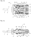
- FIG. 12 is a perspective view of the structure of the interface in the surgical-tool driving mechanism according to one or more embodiments.
- FIG. 13 is a plan view of the structure of an interface, such as is illustrated in FIG. 12 .
- FIG. 14 is a side view of the structure of an interface, such as is illustrated in FIG. 12 .
- FIGS. 12 to 14 illustrates the inside structure of the interface 272 .
- the interface 272 in the surgical-tool driving mechanism 27 has a wrist-portion driving gear 111 , first jaw driving gear 112 , second jaw driving gear 113 , first-multi-articulated-portion driving gear 114 , second-multi-articulated-portion driving gear 115 , base 116 , and frame 117 .
- the wrist-portion driving gear 111 , first jaw driving gear 112 , second jaw driving gear 113 , first-multi-articulated-portion driving gear 114 , and second-multi-articulated-portion driving gear 115 are the transmission-counterpart members and engaged with the respective transmission members 275 illustrated in FIG. 8 .
- the wrist-portion driving gear 111 , first jaw driving gear 112 , second jaw driving gear 113 , first-multi-articulated-portion driving gear 114 , and second-multi-articulated-portion driving gear 115 drive the wrist portion 23 , first jaw 22 a , second jaw 22 b , first multi-articulated portion 24 a , and second multi-articulated portion 24 b , respectively.
- the wrist-portion driving gear 111 , first jaw driving gear 112 , second jaw driving gear 113 , and base 116 are disposed inside the frame 117 .
- the first-multi-articulated-portion driving gear 114 and the second-multi-articulated-portion driving gear 115 are disposed outside the frame 117 .
- first gears When the wrist-portion driving gear 111 , first jaw driving gear 112 , and second jaw driving gear 113 are defined as “the first gears”, and the first-multi-articulated-portion driving gear 114 and second-multi-articulated-portion driving gear 115 are defined as “the second gears”, the rotation axis of the first gears and the rotation axis of the second gears intersect with each other. More specifically, the rotation axis of the first gears extends along the proximal end axis Z 2 , and the rotation axis of the second gears extends in a direction orthogonal to the proximal end axis Z 2 .
- This structure allows more arrangement variations, for example, than in the case where the gears are disposed such that their rotation axes are in parallel.
- the wrist-portion driving gear 111 , first jaw driving gear 112 , and second jaw driving gear 113 have approximately the same shape.
- all of the wrist-portion driving gear 111 , first jaw driving gear 112 , and second jaw driving gear 113 rotate on the proximal end axis Z 2 .
- the first-multi-articulated-portion driving gear 114 and the second-multi-articulated-portion driving gear 115 have approximately the same shape.
- the first-multi-articulated-portion driving gear 114 and the second-multi-articulated-portion driving gear 115 rotate on an orthogonal axis Z 3 which is orthogonal to the proximal end axis Z 2 .
- the three gears that rotate on the proximal end axis Z 2 in other words, the wrist-portion driving gear 111 , first jaw driving gear 112 , and second jaw driving gear 113 —are disposed within the length of the first-multi-articulated-portion driving gear 114 and the second-multi-articulated-portion driving gear 115 in the direction along the proximal end axis Z 2 .
- This structure allows the interface 272 to have the gears arranged within an area R, good for space saving, illustrated in FIG. 13 .
- the above described one or more embodiments makes the arrangement area for the transmission-counterpart members small, contributing space-saving.
- the base 116 has a frame shape enclosing four bevel gears 121 , 122 , 123 , and 124 described later.
- the base 116 is fixed to the wrist-portion driving gear 111 and transmits the torque of the wrist-portion driving gear 111 to the wrist portion 23 illustrated in FIG. 7 .
- the base 116 fixed to the wrist-portion driving gear 111 rotates on the proximal end axis Z 2 .
- the torque transmission tube 48 passes through the inside of the flexible shaft 2 , coupling the base 116 and the wrist portion 23 .
- the torque transmission tube 48 rotates inside the flexible shaft 2 along with the rotation of the base 116 , rotating on the distal end axis Z 1 , the wrist portion 23 illustrated in FIG. 11 , to which the torque transmission tube 48 is fixed.
- the first jaw 22 a and second jaw 22 b illustrated in FIG. 7 coupled to the wrist portion 23 rotate on the distal end axis Z 1 .
- the interface 272 also has a first conversion mechanism 151 , a second conversion mechanism 152 , a first torque transmission unit 125 , a first jaw driving pulley 126 , a second jaw driving pulley 127 , first guide pulleys 128 a and 129 a , and second guide pulleys 128 b and 129 b .
- the second guide pulleys 128 b and 129 b are not illustrated because they are hidden by the base 116 .
- the second guide pulley 129 b is disposed at a position opposite of the base 116 from the first guide pulley 129 a .
- the second guide pulley 128 b is disposed at a position opposite of the base 116 from the first guide pulley 128 a.
- first guide pulleys 128 a and 129 a and the second guide pulleys 128 b and 129 b are also simply called “guide pulleys”.
- the rotation axes of the first jaw driving pulley 126 and the second jaw driving pulley 127 are in parallel to each other and extend in directions orthogonal to the proximal end axis Z 2 .
- the first jaw driving pulley 126 and the second jaw driving pulley 127 rotate on the same rotation axis.
- the first jaw driving pulley 126 and the second jaw driving pulley 127 have different rotation planes.
- the first conversion mechanism 151 converts the torque of the rotation of the first jaw driving gear 112 into the torque to rotate the first jaw driving pulley 126 .
- the second conversion mechanism 152 converts the torque of the rotation of the second jaw driving gear 113 into the torque to rotate the second jaw driving pulley 127 .
- the first conversion mechanism 151 has the two bevel gears 121 and 122 .
- the second conversion mechanism 152 has the two bevel gears 123 and 124 .
- the bevel gears 121 , 122 , 123 , and 124 each has a conical surface, on which grooves are formed.
- the bevel gear 121 and the bevel gear 123 rotate on the proximal end axis Z 2 .
- the bevel gear 122 and the bevel gear 124 rotate on axes extending in directions orthogonal to the proximal end axis Z 2 .
- the first torque transmission unit 125 passes through the inside of the wrist-portion driving gear 111 and is fixed to the bevel gear 121 and the first jaw driving gear 112 .
- the bevel gear 121 is engaged with the bevel gear 122 .
- the first jaw driving pulley 126 is fixed to the bevel gear 122 .
- the first torque transmission unit 125 and the bevel gear 121 rotate on the proximal end axis Z 2 . Then, the rotation of the bevel gear 121 rotates the bevel gear 122 engaged with the bevel gear 121 and the first jaw driving pulley 126 fixed to the bevel gear 122 , on an axis orthogonal to the proximal end axis Z 2 .
- the interface 272 further has a second torque transmission unit 175 .
- the second torque transmission unit 175 passes through the insides of the first torque transmission unit 125 , wrist-portion driving gear 111 , and first jaw driving gear 112 and is fixed to the bevel gear 123 and the second jaw driving gear 113 .
- the bevel gear 123 is engaged with the bevel gear 124 .
- the second jaw driving pulley 127 is fixed to the bevel gear 124 .
- the second jaw driving gear 113 rotates according to an operation instruction from the controller 4 illustrated in FIG. 1
- the second torque transmission unit 175 and the bevel gear 123 rotate on the proximal end axis Z 2 .
- the rotation of the bevel gear 123 rotates the bevel gear 124 engaged with the bevel gear 123 and the second jaw driving pulley 127 fixed to the bevel gear 124 , on an axis orthogonal to the proximal end axis Z 2 .
- the use of the first conversion mechanism 151 eliminates the need for coupling the first jaw driving gear 112 and the first jaw driving pulley 126 , increasing the number of arrangement variations. Also as described above, the use of the second conversion mechanism 152 eliminates the need for coupling the second jaw driving gear 113 and the second jaw driving pulley 127 , increasing the number of arrangement variations.
- the driving device 271 in the surgical-tool driving mechanism 27 further has a first tension pulley 130 a and a second tension pulley 130 b .
- the second tension pulley 130 b is not illustrated because it is hidden by the base 116 .
- the second tension pulley 130 b is disposed at a position opposite of the base 116 from the first tension pulley 130 a .
- the first tension pulley 130 a and the second tension pulley 130 b are also simply called the “tension pulleys”.
- the jaw operating wire 46 for driving the first jaw 22 a is wound on the first jaw driving pulley 126 .
- the first end 46 a side of the jaw operating wire 46 is guided by the first guide pulley 128 a and passes through the inside of the flexible shaft 2 . Then, the first end 46 a of the jaw operating wire 46 is fixed to the first jaw 22 a illustrated in FIG. 11 .
- the second end 46 b side of the jaw operating wire 46 is guided by the second guide pulley 128 b and the second tension pulley 130 b and passes through the inside of the flexible shaft 2 . Then, the second end 46 b of the jaw operating wire 46 is fixed to the first jaw 22 a illustrated in FIG. 11 .
- the jaw operating wire 46 extends approximately in parallel with the proximal end axis Z 2 .
- the jaw operating wire 46 turns at its contact portions with the guide pulleys 128 a and 128 b .
- the angles of the bent portions (or turning portions) of the jaw operating wire 46 on the guide pulley 128 a and 128 b sides are larger than 90 degrees. If the angles are too large, it would make the surgical-tool driving mechanism 27 larger in the extending direction of the proximal end axis Z 2 . Thus, it is preferable that the angles be smaller than 120 degrees.
- the jaw operating wire 46 can be driven more smoothly than, for example, in the case where the jaw operating wire 46 is guided to turn by 90 degrees.
- the bent angles of the jaw operating wire 46 on the guide pulley 128 a and 128 b sides are smaller than or equal to 120 degrees, the wiring path of the jaw operating wire 46 is short, contributing to downsizing the surgical-tool driving mechanism 27 .
- the surgical-tool driving mechanism 27 further has a first tension pulley 131 a and a second tension pulley 131 b .
- the second tension pulley 131 b is not illustrated because it is hidden by the base 116 .
- the second tension pulley 131 b is disposed at a position opposite of the base 116 from the first tension pulley 131 a .
- the first tension pulley 131 a and the second tension pulley 131 b are also simply called the “tension pulleys”.
- the jaw operating wire 47 for driving the second jaw 22 b is wound on the second jaw driving pulley 127 .
- the first end 47 a side of the jaw operating wire 47 is guided by the first guide pulley 129 a and the first tension pulley 131 a and passes through the inside of the flexible shaft 2 . Then, the first end 47 a of the jaw operating wire 47 is fixed to the second jaw 22 b illustrated in FIG. 11 .
- the second end 47 b side of the jaw operating wire 47 is guided by the second guide pulley 129 b and the second tension pulley 131 b and passes through the inside of the flexible shaft 2 . Then, the second end 47 b of the jaw operating wire 47 is fixed to the second jaw 22 b illustrated in FIG. 11 .
- the jaw operating wire 47 extends approximately in parallel with the proximal end axis Z 2 .
- the jaw operating wire 47 turns at its contact portions with the guide pulleys 129 a and 129 b .
- the angles of the bent portions of the jaw operating wire 47 on the guide pulley 129 a and 129 b sides are larger than 90 degrees. If the angles are too large, it would make the surgical-tool driving mechanism 27 larger in the extending direction of the proximal end axis Z 2 . Thus, it is preferable that the angles be smaller than 120 degrees.
- the jaw operating wire 47 can be driven more smoothly than, for example, in the case where the jaw operating wire 47 is guided to turn by 90 degrees.
- the bent angles of the jaw operating wire 47 on the guide pulley 129 a and 129 b sides are smaller than or equal to 120 degrees, the wiring path of the jaw operating wire 47 is short, contributing to downsizing the surgical-tool driving mechanism 27 .
- the bevel gears 121 , 122 , 123 , and 124 , the first jaw driving pulley 126 , the second jaw driving pulley 127 , the guide pulleys 128 a , 128 b , 129 a , and 129 b , the tension pulleys 130 a , 130 b , 131 a , and 131 b , the first conversion mechanism 151 , and the second conversion mechanism 152 are attached to the base 116 .
- first torque transmission unit 125 and the second torque transmission unit 175 illustrated in FIG. 13 rotate on the proximal end axis Z 2 , independently of the wrist-portion driving gear 111 for rotating the base 116 .
- first jaw 22 a and the second jaw 22 b can be driven independently of the rotation of the wrist portion 23 .
- the surgical-tool driving mechanism 27 further has a first-multi-articulated-portion driving pulley 132 , a second-multi-articulated-portion driving pulley 133 , first guide pulleys 134 a and 135 a , second guide pulleys 134 b and 135 b , first tension pulleys 136 a and 137 a , and second tension pulleys 136 b and 137 b .
- the second guide pulleys 134 b and 135 b are not illustrated because they are hidden by the frame 117 .
- the second guide pulley 135 b is disposed at a position opposite of the frame 117 from the first guide pulley 135 a .
- the second guide pulley 134 b is disposed at a position opposite of the frame 117 from the first guide pulley 134 a.
- first guide pulleys 134 a and 135 a and the second guide pulleys 134 b and 135 b are also simply called the “guide pulleys”.
- first tension pulleys 136 a and 137 a and the second tension pulleys 136 b and 137 b are also simply called the “tension pulleys”.
- the second tension pulleys 136 b and 137 b are not illustrated because they are hidden by the frame 117 .
- the second tension pulley 136 b is disposed at a position opposite of the frame 117 from the first tension pulley 136 a .
- the second tension pulley 137 b is disposed at a position opposite of the frame 117 from the first tension pulley 137 a.
- the rotation axes of the first-multi-articulated-portion driving pulley 132 and the second-multi-articulated-portion driving pulley 133 are in parallel to each other and extend in directions orthogonal to the proximal end axis Z 2 .
- the first-multi-articulated-portion driving pulley 132 and the second-multi-articulated-portion driving pulley 133 have different rotation planes.
- the first-multi-articulated-portion driving pulley 132 and the second-multi-articulated-portion driving pulley 133 are disposed outside the frame 117 .
- This structure in which at least one of the driving pulleys in the surgical-tool driving mechanism 27 is disposed outside of the frame 117 as above is preferable because it is easy to wind an elongate element to the driving pulley.
- the first-multi-articulated-portion driving pulley 132 rotates in conjunction with the first-multi-articulated-portion driving gear 114 .
- On the first-multi-articulated-portion driving pulley 132 is wound the multi-articulated portion operating wire 41 a.
- the first end side of the multi-articulated portion operating wire 41 a is guided by the first guide pulley 134 a and the first tension pulley 136 a and passes through the inside of the flexible shaft 2 . Then, the first end of the multi-articulated portion operating wire 41 a is fixed to the distal end side fixing point 45 a 1 of the first multi-articulated portion 24 a illustrated in FIG. 10B .
- the second end side of the multi-articulated portion operating wire 41 a is guided by the second guide pulley 134 b and the second tension pulley 136 b and passes through the inside of the flexible shaft 2 . Then, the second end of the multi-articulated portion operating wire 41 a is fixed to the distal end side fixing point 45 a 2 of the first multi-articulated portion 24 a illustrated in FIG. 10B . Note that as illustrated in FIG. 10B , the distal end side fixing point 45 a 1 and the distal end side fixing point 45 a 2 are disposed with some distance in between.
- the multi-articulated portion operating wire 41 a extends approximately in parallel with the proximal end axis Z 2 .
- the first-multi-articulated-portion driving pulley 132 rotates on the axis orthogonal to the proximal end axis Z 2 .
- the rotation of the first-multi-articulated-portion driving pulley 132 moves the multi-articulated portion operating wire 41 a , bending the first multi-articulated portion 24 a illustrated in FIG. 10A .
- the multi-articulated portion operating wire 41 a turns at its contact portions with the guide pulleys 134 a and 134 b .
- the angles of the bent portions of the multi-articulated portion operating wire 41 a on the guide pulley 134 a and 134 b sides are larger than 90 degrees. If the angles are too large, it would make the surgical-tool driving mechanism 27 larger in the extending direction of the proximal end axis Z 2 . Thus, it is preferable that the angles be smaller than 120 degrees.
- the multi-articulated portion operating wire 41 a can be driven more smoothly than, for example, in the case where the multi-articulated portion operating wire 41 a is guided to turn by 90 degrees.
- the bent angles of the multi-articulated portion operating wire 41 a on the guide pulley 134 a and 134 b sides are smaller than or equal to 120 degrees, the wiring path of the multi-articulated portion operating wire 41 a is short, contributing to downsizing the surgical-tool driving mechanism 27 .
- the second-multi-articulated-portion driving pulley 133 rotates in conjunction with the second-multi-articulated-portion driving gear 115 .
- On the second-multi-articulated-portion driving pulley 133 is wound the multi-articulated portion operating wire 41 b.
- the first end side of the multi-articulated portion operating wire 41 b is guided by the first guide pulley 135 a and the first tension pulley 137 a and passes through the inside of the flexible shaft 2 . Then, the first end of the multi-articulated portion operating wire 41 b is fixed to the distal end side fixing point 45 b 1 of the second multi-articulated portion 24 b illustrated in FIG. 10C .
- the second end side of the multi-articulated portion operating wire 41 b is guided by the second guide pulley 135 b and the second tension pulley 137 b and passes through the inside of the flexible shaft 2 . Then, the second end of the multi-articulated portion operating wire 41 b is fixed to the distal end side fixing point 45 b 2 of the second multi-articulated portion 24 b illustrated in FIG. 10C . Note that as illustrated in FIG. 10C , the distal end side fixing point 45 b 1 and the distal end side fixing point 45 b 2 are disposed with some distance in between.
- the multi-articulated portion operating wire 41 b extends approximately in parallel with the proximal end axis Z 2 .
- the second-multi-articulated-portion driving pulley 133 rotates on the axis orthogonal to the proximal end axis Z 2 .
- the rotation of the second-multi-articulated-portion driving pulley 133 moves the multi-articulated portion operating wire 41 b , bending the second multi-articulated portion 24 b illustrated in FIG. 10A .
- the multi-articulated portion operating wire 41 b turns at its contact portions with the guide pulleys 135 a and 135 b .
- the angles of the bent portions of the multi-articulated portion operating wire 41 b on the guide pulley 135 a and 135 b sides are larger than 90 degrees. If the angles are too large, it would make the surgical-tool driving mechanism 27 larger in the extending direction of the proximal end axis Z 2 . Thus, it is preferable that the angles be smaller than 120 degrees.
- the multi-articulated portion operating wire 41 b can be driven more smoothly than, for example, in the case where the multi-articulated portion operating wire 41 b is guided to turn by 90 degrees.
- the bent angles of the multi-articulated portion operating wire 41 b on the guide pulley 135 a and 135 b sides are smaller than or equal to 120 degrees, the wiring path of the multi-articulated portion operating wire 41 b is short, contributing to downsizing the surgical-tool driving mechanism 27 .
- the jaw operating wires 46 and 47 may get loose or slack, for example, for the reason that tension is exerted on them for a long time.
- the jaw operating wires 46 and 47 may get loose or slack to a large extent.
- the multi-articulated portion operating wires 41 a and 41 b may also get loose or slack in the same way as the jaw operating wires 46 and 47 .
- the multi-articulated portion operating wires 41 a and 41 b may get loose or slack to a large extent.
- a problem is that in the case where the jaw operating wire 46 gets loose or slack, the jaw operating wire 46 may come off the guide pulley 128 a or 128 b , or it may take some time for the jaw operating wire 46 to transmit torque, making unable to operate the first jaw 22 a as desired.
- the guide pulleys 128 a , 128 b , 129 a , 129 b , 134 a , 134 b , 135 a , and 135 b and the tension pulleys 130 a , 130 b , 131 a , 131 b , 136 a , 136 b , 137 a , and 137 b are provided with tension adjusting mechanisms which adjust the wire tensions, as described below.
- the tension pulleys 130 a and 130 b are disposed closer to the flexible shaft 2 than the guide pulleys 128 a and 128 b .
- Each of the tension pulleys 130 a and 130 b is movable in the circumferential direction of a circle centered on the corresponding guide pulley 128 a or 128 b and is urged.
- the tension pulleys 130 a and 130 b are disposed in the paths of the jaw operating wire 46 from the guide pulleys 128 a and 128 b to the proximal end portion 2 a .
- the tension pulleys 130 a and 130 b bias straight line portions of the jaw operating wire 46 in directions oblique to the straight line portions.
- This structure improves the smoothness and endurance of driving the jaw operating wire 46 , compared to, for example, the case of urging the jaw operating wire 46 by bending it at 90 degrees. In addition, there is no need for allocating a large space for the tension pulleys 130 a and 130 b , thus contributing to downsizing the driving mechanism 27 of the surgical tool.
- the tension pulleys 131 a and 131 b are disposed closer to the flexible shaft 2 than the guide pulleys 129 a and 129 b .
- Each of the tension pulleys 131 a and 131 b is movable in the circumferential direction of a circle centered on the corresponding guide pulley 129 a or 129 b and is urged.
- the tension pulleys 131 a and 131 b are disposed in the paths of the jaw operating wire 47 from the guide pulleys 129 a and 129 b to the proximal end portion 2 a .
- the tension pulleys 131 a and 131 b bias or urge straight line portions of the jaw operating wire 47 in directions oblique to the straight line portions.
- This structure improves the smoothness and endurance of driving the jaw operating wire 47 , compared to, for example, the case of urging the jaw operating wire 47 by bending it at 90 degrees. In addition, there is no need for allocating large spaces for the tension pulleys 131 a and 131 b , thus contributing to downsizing the driving mechanism 27 of the surgical tool.
- the tension pulleys 130 a and 130 b receive urging forces from not-illustrated elastic members, such as springs, and bias the jaw operating wire 46 in the directions that are circumferential directions of circles centered on the guide pulleys 128 a and 128 b and directions away from the proximal end axis Z 2 .
- the tension pulleys 131 a and 131 b receive urging forces from not-illustrated elastic members, such as springs, and bias the jaw operating wire 47 in the directions that are circumferential directions of circles centered on the guide pulleys 129 a and 129 b and directions away from the proximal end axis Z 2 .
- the tension pulleys 130 a and 130 b move in the directions that are circumferential directions of circles centered on the guide pulleys 128 a and 128 b and directions away from the proximal end axis Z 2 . This prevents the tension exerted on the jaw operating wire 46 from becoming too small.
- the tension exerted on the jaw operating wire 46 is stable as described above, preventing the jaw operating wire 46 from getting loose or slack without disturbing the movement of the jaw operating wire 46 .
- the tension pulleys 131 a and 131 b move in circumferential directions of circles centered on the guide pulleys 129 a and 129 b according to the magnitude of the tension exerted on the jaw operating wire 47 .
- the tension pulleys 130 a and 130 b may be deposed closer to the first jaw driving pulley 126 than the guide pulleys 128 a and 128 b .
- the structure in which the tension pulleys 130 a and 130 b are disposed in the spaces between the guide pulleys 128 a and 128 b and the proximal end portion 2 a is preferable because space can be used effectively.
- the tension pulleys 131 a and 131 b are disposed closer to the second jaw driving pulley 127 than the guide pulleys 129 a and 129 b .
- the structure in which the tension pulleys 131 a and 131 b are disposed between the guide pulley 129 a and 129 b and the proximal end portion 2 a is preferable.
- tension pulleys 130 a , 130 b , 131 a , and 131 b may be movable in the circumferential directions of circles centered on parts different from the guide pulleys 128 a , 128 b , 129 a , and 129 b.
- the tension pulleys 136 a and 136 b are disposed closer to the flexible shaft 2 than the guide pulleys 134 a and 134 b .
- Each of the tension pulleys 136 a and 136 b is movable in the circumferential direction of a circle centered on the corresponding guide pulley 134 a or 134 b and is urged.
- the tension pulleys 136 a and 136 b are disposed in the paths of the multi-articulated portion operating wire 41 a from the guide pulleys 134 a and 134 b to the proximal end portion 2 a .
- the tension pulleys 136 a and 136 b bias straight line portions of the multi-articulated portion operating wire 41 a in directions oblique to the straight line portions.
- This structure improves the smoothness and endurance of driving the multi-articulated portion operating wire 41 a , compared to, for example, the case of urging the multi-articulated portion operating wire 41 a by bending it at 90 degrees.
- the tension pulleys 137 a and 137 b are disposed closer to the flexible shaft 2 than the guide pulleys 135 a and 135 b .
- Each of the tension pulleys 137 a and 137 b is movable in the circumferential direction of a circle centered on the corresponding guide pulley 135 a or 135 b and is urged.
- the tension pulleys 137 a and 137 b are disposed in the paths of the multi-articulated portion operating wire 41 b from the guide pulleys 135 a and 135 b to the proximal end portion 2 a .
- the tension pulleys 137 a and 137 b bias straight line portions of the multi-articulated portion operating wire 41 b in directions oblique to the straight line portions.
- This structure improves the smoothness and endurance of driving the multi-articulated portion operating wire 41 b , compared to, for example, the case of urging the multi-articulated portion operating wire 41 b by turning it at 90 degrees.
- there is no need for allocating large spaces for the tension pulleys 137 a and 137 b thus contributing to downsizing the driving mechanism 27 of the surgical tool.
- the tension pulleys 136 a and 136 b receive urging forces from not-illustrated elastic members, such as springs, and are urged in the directions that are circumferential directions of circles centered on the guide pulleys 134 a and 134 b and directions away from the proximal end axis Z 2 .
- the tension pulleys 137 a and 137 b receive urging forces from not-illustrated elastic members, such as springs, and are urged in the directions that are circumferential directions of circles centered on the guide pulleys 135 a and 135 b and directions away from the proximal end axis Z 2 .
- the tension pulleys 136 a and 136 b move in the directions that are circumferential directions of circles centered on the guide pulleys 134 a and 134 b and directions away from the proximal end axis Z 2 . This prevents the tension exerted on the jaw operating wire 46 from becoming too small.
- the tension exerted on the multi-articulated portion operating wire 41 a is stable as described above, preventing the multi-articulated portion operating wire 41 a from getting loose or slack without disturbing the movement of the multi-articulated portion operating wire 41 a.
- the tension pulleys 137 a and 137 b move in circumferential directions of circles centered on the guide pulleys 135 a and 135 b according to the magnitude of the tension exerted on the multi-articulated portion operating wire 41 b.
- the tension pulleys 136 a and 136 b may be deposed closer to the first-multi-articulated-portion driving pulley 132 than the guide pulleys 134 a and 134 b .
- the structure in which the tension pulleys 136 a and 136 b are disposed in the spaces between the guide pulleys 134 a and 134 b and the proximal end portion 2 a is preferable because space can be used effectively.
- the tension pulleys 137 a and 137 b are disposed closer to the second-multi-articulated-portion driving pulley 133 than the guide pulleys 135 a and 135 b .
- the structure in which the tension pulleys 137 a and 137 b are disposed between the guide pulley 135 a and 135 b and the proximal end portion 2 a is preferable.
- tension pulleys 136 a , 136 b , 137 a , and 137 b may be movable in the circumferential directions of circles centered on parts different from the guide pulleys 134 a , 134 b , 135 a , and 135 b.
- one or more embodiments can achieve a tension adjusting mechanism that is small but capable of adjusting the tension of an elongate element for driving an end effector, and an interface and driving mechanism including the tension adjusting mechanisms.
- the driving mechanism and the tension adjusting mechanism can be applied not only to medical treatment instruments 101 including a guide tube 11 and a bundling tube 12 but also to wide varieties of mechanisms for driving medical treatment instruments.
Landscapes
- Health & Medical Sciences (AREA)
- Engineering & Computer Science (AREA)
- Life Sciences & Earth Sciences (AREA)
- Surgery (AREA)
- Robotics (AREA)
- Medical Informatics (AREA)
- Biomedical Technology (AREA)
- Heart & Thoracic Surgery (AREA)
- Nuclear Medicine, Radiotherapy & Molecular Imaging (AREA)
- Molecular Biology (AREA)
- Animal Behavior & Ethology (AREA)
- General Health & Medical Sciences (AREA)
- Public Health (AREA)
- Veterinary Medicine (AREA)
- Ophthalmology & Optometry (AREA)
- Surgical Instruments (AREA)
Abstract
Description
Claims (14)
Applications Claiming Priority (3)
| Application Number | Priority Date | Filing Date | Title |
|---|---|---|---|
| JP2017-059891 | 2017-03-24 | ||
| JP2017059891 | 2017-03-24 | ||
| PCT/JP2018/011612 WO2018174226A1 (en) | 2017-03-24 | 2018-03-23 | Tension adjustment mechanism, interface, and drive mechanism |
Related Parent Applications (1)
| Application Number | Title | Priority Date | Filing Date |
|---|---|---|---|
| PCT/JP2018/011612 Continuation WO2018174226A1 (en) | 2017-03-24 | 2018-03-23 | Tension adjustment mechanism, interface, and drive mechanism |
Publications (2)
| Publication Number | Publication Date |
|---|---|
| US20190201149A1 US20190201149A1 (en) | 2019-07-04 |
| US11219496B2 true US11219496B2 (en) | 2022-01-11 |
Family
ID=63585799
Family Applications (1)
| Application Number | Title | Priority Date | Filing Date |
|---|---|---|---|
| US16/262,949 Active 2038-09-07 US11219496B2 (en) | 2017-03-24 | 2019-01-31 | Surgical tool, medical treatment instrument, and surgical system |
Country Status (3)
| Country | Link |
|---|---|
| US (1) | US11219496B2 (en) |
| JP (1) | JP6653044B2 (en) |
| WO (1) | WO2018174226A1 (en) |
Families Citing this family (10)
| Publication number | Priority date | Publication date | Assignee | Title |
|---|---|---|---|---|
| CN109199591A (en) * | 2018-10-19 | 2019-01-15 | 上海交通大学 | Ear nose basis cranii micro-wound operation robot and its operating method |
| JP6870010B2 (en) | 2019-01-21 | 2021-05-12 | 株式会社メディカロイド | Surgical system and support device |
| JP6954937B2 (en) | 2019-01-25 | 2021-10-27 | 株式会社メディカロイド | Surgical instruments |
| WO2022001187A1 (en) * | 2020-06-30 | 2022-01-06 | 北京术锐技术有限公司 | Continuous body instrument and surgical robot |
| CN120983156A (en) * | 2020-12-19 | 2025-11-21 | 深圳市精锋医疗科技股份有限公司 | Surgical instruments, operating equipment, and surgical robots |
| US12329486B2 (en) * | 2021-01-20 | 2025-06-17 | Cilag Gmbh International | Drive cable accumulation systems for robotic surgical tools |
| WO2023100178A1 (en) * | 2021-12-01 | 2023-06-08 | Tamar Robotics Ltd | Robotic endoscope configuration for tissue removal |
| CN114404044B (en) * | 2022-02-16 | 2024-04-05 | 上海交通大学 | A continuum-configuration minimally invasive surgical robot and its working method |
| CN115778493B (en) * | 2022-12-21 | 2023-10-20 | 鼎科医疗技术(苏州)有限公司 | Foreign body forceps for blood vessel |
| CN116098762B (en) * | 2023-02-06 | 2024-02-20 | 哈尔滨工业大学 | An inner ear injection-sampling actuator for otological surgical robots |
Citations (12)
| Publication number | Priority date | Publication date | Assignee | Title |
|---|---|---|---|---|
| JP2006061364A (en) | 2004-08-26 | 2006-03-09 | Hitachi Ltd | Surgical instruments |
| WO2008136160A1 (en) | 2007-04-20 | 2008-11-13 | Olympus Medical Systems Corp. | Operating tool and endoscopic operating system including the same |
| US20100015570A1 (en) | 2008-07-18 | 2010-01-21 | Degudent Gmbh | Procedure for dimensionally accurate sintering of a shaped piece |
| JP2010253162A (en) | 2009-04-28 | 2010-11-11 | Terumo Corp | Medical robot system |
| JP2012504016A (en) | 2008-09-30 | 2012-02-16 | インテュイティブ サージカル オペレーションズ, インコーポレイテッド | Passive preload and capstan drive for surgical instruments |
| JP2013103074A (en) | 2011-11-16 | 2013-05-30 | Olympus Corp | Medical treatment tool and manipulator including the same |
| US20140257333A1 (en) * | 2013-03-07 | 2014-09-11 | Intuitive Surgical Operations, Inc. | Hybrid manual and robotic interventional instruments and methods of use |
| JP2015024007A (en) | 2013-07-26 | 2015-02-05 | オリンパス株式会社 | Manipulator and manipulator system |
| JP2016000432A (en) | 2014-06-11 | 2016-01-07 | キヤノン電子株式会社 | Parallel link robot |
| JP2016016242A (en) | 2014-07-10 | 2016-02-01 | オリンパス株式会社 | Medical device and method for adjusting medical device |
| WO2016161449A1 (en) | 2015-04-03 | 2016-10-06 | The Regents Of The University Of Michigan | Tension management apparatus for cable-driven transmission |
| WO2017006374A1 (en) | 2015-07-09 | 2017-01-12 | 川崎重工業株式会社 | Slewing device and surgical instrument |
Family Cites Families (2)
| Publication number | Priority date | Publication date | Assignee | Title |
|---|---|---|---|---|
| US9308049B2 (en) * | 2006-01-13 | 2016-04-12 | Olympus Corporation | Medical treatment endoscope |
| JP5921943B2 (en) * | 2012-04-12 | 2016-05-24 | カール シュトルツ ゲゼルシャフト ミット ベシュレンクテル ハフツング ウント コンパニー コマンディートゲゼルシャフト | Medical manipulator |
-
2018
- 2018-03-23 WO PCT/JP2018/011612 patent/WO2018174226A1/en not_active Ceased
- 2018-03-23 JP JP2019507010A patent/JP6653044B2/en active Active
-
2019
- 2019-01-31 US US16/262,949 patent/US11219496B2/en active Active
Patent Citations (20)
| Publication number | Priority date | Publication date | Assignee | Title |
|---|---|---|---|---|
| JP2006061364A (en) | 2004-08-26 | 2006-03-09 | Hitachi Ltd | Surgical instruments |
| WO2008136160A1 (en) | 2007-04-20 | 2008-11-13 | Olympus Medical Systems Corp. | Operating tool and endoscopic operating system including the same |
| US20100022837A1 (en) | 2007-04-20 | 2010-01-28 | Tsutomu Ishiguro | Surgical instrument and endoscope surgical system having surgical instrument |
| US20100015570A1 (en) | 2008-07-18 | 2010-01-21 | Degudent Gmbh | Procedure for dimensionally accurate sintering of a shaped piece |
| JP2010022837A (en) | 2008-07-18 | 2010-02-04 | Degudent Gmbh | Method for sintering molded article in dimensionally accurate fashion |
| JP2012504016A (en) | 2008-09-30 | 2012-02-16 | インテュイティブ サージカル オペレーションズ, インコーポレイテッド | Passive preload and capstan drive for surgical instruments |
| US9259274B2 (en) | 2008-09-30 | 2016-02-16 | Intuitive Surgical Operations, Inc. | Passive preload and capstan drive for surgical instruments |
| JP2010253162A (en) | 2009-04-28 | 2010-11-11 | Terumo Corp | Medical robot system |
| JP2013103074A (en) | 2011-11-16 | 2013-05-30 | Olympus Corp | Medical treatment tool and manipulator including the same |
| US9775677B2 (en) | 2011-11-16 | 2017-10-03 | Olympus Corporation | Medical treatment tool and manipulator including the same |
| US20140257333A1 (en) * | 2013-03-07 | 2014-09-11 | Intuitive Surgical Operations, Inc. | Hybrid manual and robotic interventional instruments and methods of use |
| US20160135663A1 (en) | 2013-07-26 | 2016-05-19 | Olympus Corporation | Manipulator and manipulator system |
| JP2015024007A (en) | 2013-07-26 | 2015-02-05 | オリンパス株式会社 | Manipulator and manipulator system |
| JP2016000432A (en) | 2014-06-11 | 2016-01-07 | キヤノン電子株式会社 | Parallel link robot |
| US20170105805A1 (en) | 2014-07-10 | 2017-04-20 | Olympus Corporation | Medical instrument and adjustment method of medical instrument |
| JP2016016242A (en) | 2014-07-10 | 2016-02-01 | オリンパス株式会社 | Medical device and method for adjusting medical device |
| WO2016161449A1 (en) | 2015-04-03 | 2016-10-06 | The Regents Of The University Of Michigan | Tension management apparatus for cable-driven transmission |
| US20180080533A1 (en) | 2015-04-03 | 2018-03-22 | The Regents Of The University Of Michigan | Tension management apparatus for cable-driven transmission |
| WO2017006374A1 (en) | 2015-07-09 | 2017-01-12 | 川崎重工業株式会社 | Slewing device and surgical instrument |
| US20180215051A1 (en) | 2015-07-09 | 2018-08-02 | Kawasaki Jukogyo Kabushiki Kaisha | Turning device and medical instrument |
Also Published As
| Publication number | Publication date |
|---|---|
| WO2018174226A1 (en) | 2018-09-27 |
| JP6653044B2 (en) | 2020-02-26 |
| JPWO2018174226A1 (en) | 2019-06-27 |
| US20190201149A1 (en) | 2019-07-04 |
Similar Documents
| Publication | Publication Date | Title |
|---|---|---|
| US11219496B2 (en) | Surgical tool, medical treatment instrument, and surgical system | |
| US20190159852A1 (en) | Surgical tool, medical treatment instrument, and surgical system | |
| JP6945683B2 (en) | Robot Surgical Surgery Assembly | |
| US11141236B2 (en) | Instrument holder | |
| US8092371B2 (en) | Medical treatment endoscope | |
| JP4799490B2 (en) | Articulated surgical instrument for performing minimally invasive surgery with improved sophistication and sensitivity | |
| US8617054B2 (en) | Medical treatment endoscope | |
| WO2018041218A1 (en) | Flexible surgical instrument system | |
| US12349937B2 (en) | Continuum instrument and surgical robot | |
| US11324560B2 (en) | Surgical instrument | |
| JP2008220972A (en) | Treatment instrument | |
| EP4173588B1 (en) | Continuum instrument and surgical robot | |
| CN106308938A (en) | Flexible operation tool system capable of passing through natural orifice | |
| US20080132755A1 (en) | Medical device | |
| JP2008220971A (en) | Treatment instrument | |
| JP7096393B2 (en) | Surgical system and support device | |
| US20190159854A1 (en) | Surgical system | |
| JP4145309B2 (en) | Treatment tool | |
| JP2022191607A (en) | Medical device and surgery system | |
| WO2023032145A1 (en) | Treatment apparatus, treatment tool manipulation device, treatment system, and treatment tool manipulation method |
Legal Events
| Date | Code | Title | Description |
|---|---|---|---|
| FEPP | Fee payment procedure |
Free format text: ENTITY STATUS SET TO UNDISCOUNTED (ORIGINAL EVENT CODE: BIG.); ENTITY STATUS OF PATENT OWNER: LARGE ENTITY |
|
| AS | Assignment |
Owner name: MEDICAROID CORPORATION, JAPAN Free format text: ASSIGNMENT OF ASSIGNORS INTEREST;ASSIGNORS:ITO, TETSUSHI;KAN, KAZUTOSHI;SIGNING DATES FROM 20190129 TO 20190201;REEL/FRAME:048350/0917 |
|
| STPP | Information on status: patent application and granting procedure in general |
Free format text: DOCKETED NEW CASE - READY FOR EXAMINATION |
|
| STPP | Information on status: patent application and granting procedure in general |
Free format text: RESPONSE TO NON-FINAL OFFICE ACTION ENTERED AND FORWARDED TO EXAMINER |
|
| STPP | Information on status: patent application and granting procedure in general |
Free format text: NON FINAL ACTION MAILED |
|
| STPP | Information on status: patent application and granting procedure in general |
Free format text: RESPONSE TO NON-FINAL OFFICE ACTION ENTERED AND FORWARDED TO EXAMINER |
|
| STPP | Information on status: patent application and granting procedure in general |
Free format text: NOTICE OF ALLOWANCE MAILED -- APPLICATION RECEIVED IN OFFICE OF PUBLICATIONS |
|
| STPP | Information on status: patent application and granting procedure in general |
Free format text: PUBLICATIONS -- ISSUE FEE PAYMENT VERIFIED |
|
| STCF | Information on status: patent grant |
Free format text: PATENTED CASE |
|
| CC | Certificate of correction | ||
| MAFP | Maintenance fee payment |
Free format text: PAYMENT OF MAINTENANCE FEE, 4TH YEAR, LARGE ENTITY (ORIGINAL EVENT CODE: M1551); ENTITY STATUS OF PATENT OWNER: LARGE ENTITY Year of fee payment: 4 |