US11219424B2 - Systems and methods for characterizing a central axis of a bone from a 3D anatomical image - Google Patents
Systems and methods for characterizing a central axis of a bone from a 3D anatomical image Download PDFInfo
- Publication number
- US11219424B2 US11219424B2 US16/724,722 US201916724722A US11219424B2 US 11219424 B2 US11219424 B2 US 11219424B2 US 201916724722 A US201916724722 A US 201916724722A US 11219424 B2 US11219424 B2 US 11219424B2
- Authority
- US
- United States
- Prior art keywords
- bone
- interest
- mask
- processor
- binary
- Prior art date
- Legal status (The legal status is an assumption and is not a legal conclusion. Google has not performed a legal analysis and makes no representation as to the accuracy of the status listed.)
- Active, expires
Links
Images


Classifications
-
- A—HUMAN NECESSITIES
- A61—MEDICAL OR VETERINARY SCIENCE; HYGIENE
- A61B—DIAGNOSIS; SURGERY; IDENTIFICATION
- A61B6/00—Apparatus or devices for radiation diagnosis; Apparatus or devices for radiation diagnosis combined with radiation therapy equipment
- A61B6/50—Apparatus or devices for radiation diagnosis; Apparatus or devices for radiation diagnosis combined with radiation therapy equipment specially adapted for specific body parts; specially adapted for specific clinical applications
- A61B6/505—Apparatus or devices for radiation diagnosis; Apparatus or devices for radiation diagnosis combined with radiation therapy equipment specially adapted for specific body parts; specially adapted for specific clinical applications for diagnosis of bone
-
- A—HUMAN NECESSITIES
- A61—MEDICAL OR VETERINARY SCIENCE; HYGIENE
- A61B—DIAGNOSIS; SURGERY; IDENTIFICATION
- A61B6/00—Apparatus or devices for radiation diagnosis; Apparatus or devices for radiation diagnosis combined with radiation therapy equipment
- A61B6/02—Arrangements for diagnosis sequentially in different planes; Stereoscopic radiation diagnosis
- A61B6/03—Computed tomography [CT]
- A61B6/032—Transmission computed tomography [CT]
-
- A—HUMAN NECESSITIES
- A61—MEDICAL OR VETERINARY SCIENCE; HYGIENE
- A61B—DIAGNOSIS; SURGERY; IDENTIFICATION
- A61B6/00—Apparatus or devices for radiation diagnosis; Apparatus or devices for radiation diagnosis combined with radiation therapy equipment
- A61B6/52—Devices using data or image processing specially adapted for radiation diagnosis
- A61B6/5211—Devices using data or image processing specially adapted for radiation diagnosis involving processing of medical diagnostic data
- A61B6/5217—Devices using data or image processing specially adapted for radiation diagnosis involving processing of medical diagnostic data extracting a diagnostic or physiological parameter from medical diagnostic data
-
- G—PHYSICS
- G06—COMPUTING OR CALCULATING; COUNTING
- G06T—IMAGE DATA PROCESSING OR GENERATION, IN GENERAL
- G06T7/00—Image analysis
- G06T7/0002—Inspection of images, e.g. flaw detection
- G06T7/0012—Biomedical image inspection
-
- G—PHYSICS
- G06—COMPUTING OR CALCULATING; COUNTING
- G06T—IMAGE DATA PROCESSING OR GENERATION, IN GENERAL
- G06T7/00—Image analysis
- G06T7/60—Analysis of geometric attributes
- G06T7/62—Analysis of geometric attributes of area, perimeter, diameter or volume
-
- G—PHYSICS
- G16—INFORMATION AND COMMUNICATION TECHNOLOGY [ICT] SPECIALLY ADAPTED FOR SPECIFIC APPLICATION FIELDS
- G16H—HEALTHCARE INFORMATICS, i.e. INFORMATION AND COMMUNICATION TECHNOLOGY [ICT] SPECIALLY ADAPTED FOR THE HANDLING OR PROCESSING OF MEDICAL OR HEALTHCARE DATA
- G16H50/00—ICT specially adapted for medical diagnosis, medical simulation or medical data mining; ICT specially adapted for detecting, monitoring or modelling epidemics or pandemics
- G16H50/30—ICT specially adapted for medical diagnosis, medical simulation or medical data mining; ICT specially adapted for detecting, monitoring or modelling epidemics or pandemics for calculating health indices; for individual health risk assessment
-
- G—PHYSICS
- G06—COMPUTING OR CALCULATING; COUNTING
- G06T—IMAGE DATA PROCESSING OR GENERATION, IN GENERAL
- G06T2207/00—Indexing scheme for image analysis or image enhancement
- G06T2207/10—Image acquisition modality
- G06T2207/10072—Tomographic images
- G06T2207/10081—Computed x-ray tomography [CT]
-
- G—PHYSICS
- G06—COMPUTING OR CALCULATING; COUNTING
- G06T—IMAGE DATA PROCESSING OR GENERATION, IN GENERAL
- G06T2207/00—Indexing scheme for image analysis or image enhancement
- G06T2207/20—Special algorithmic details
- G06T2207/20036—Morphological image processing
-
- G—PHYSICS
- G06—COMPUTING OR CALCULATING; COUNTING
- G06T—IMAGE DATA PROCESSING OR GENERATION, IN GENERAL
- G06T2207/00—Indexing scheme for image analysis or image enhancement
- G06T2207/20—Special algorithmic details
- G06T2207/20036—Morphological image processing
- G06T2207/20044—Skeletonization; Medial axis transform
-
- G—PHYSICS
- G06—COMPUTING OR CALCULATING; COUNTING
- G06T—IMAGE DATA PROCESSING OR GENERATION, IN GENERAL
- G06T2207/00—Indexing scheme for image analysis or image enhancement
- G06T2207/30—Subject of image; Context of image processing
- G06T2207/30004—Biomedical image processing
- G06T2207/30008—Bone
-
- G—PHYSICS
- G06—COMPUTING OR CALCULATING; COUNTING
- G06T—IMAGE DATA PROCESSING OR GENERATION, IN GENERAL
- G06T2207/00—Indexing scheme for image analysis or image enhancement
- G06T2207/30—Subject of image; Context of image processing
- G06T2207/30004—Biomedical image processing
- G06T2207/30024—Cell structures in vitro; Tissue sections in vitro
-
- G—PHYSICS
- G06—COMPUTING OR CALCULATING; COUNTING
- G06T—IMAGE DATA PROCESSING OR GENERATION, IN GENERAL
- G06T2207/00—Indexing scheme for image analysis or image enhancement
- G06T2207/30—Subject of image; Context of image processing
- G06T2207/30172—Centreline of tubular or elongated structure
Definitions
- This invention relates generally to methods and systems of image analysis. More particularly, in certain embodiments, the invention relates to detection and localization of a bone central axis from an image of a subject (e.g., mammal), e.g., captured with a computed tomography (CT) scanner.
- a subject e.g., mammal
- CT computed tomography
- Micro computed tomography (hereafter, “microCT”) imaging, is an x-ray-based technology that can image tissues, organs, and non-organic structures with an extremely high resolution. MicroCT has evolved quickly, requiring low dose scanning and fast imaging protocols to facilitate multi-modal applications and enable longitudinal experimental models. Similarly, nano-computed tomography (nanoCT) systems designed for high-resolution imaging of ex vivo samples are also now used. Multi-modal imaging involves the fusion of images obtained in different ways, for example, by combining fluorescence molecular tomography (FMT), PET, MRI, CT, and/or SPECT imaging data.
- FMT fluorescence molecular tomography
- volume rendering tools e.g., volumetric compositing, depth shading, gradient shading, maximum intensity projection, summed voxel projection, signal projection
- manipulation functions e.g., to define areas of structures of interest, delete unwanted objects, edit images and object maps
- measurement functions e.g., calculation of number of surface voxels, number of exposed faces, planar area of a region, estimated surface area of a region.
- Three dimensional (3D) imaging software including microCT image analysis, enables extraction of structural, biological, and anatomical attributes from images, such as thickness, porosity, anisotropy, and other measures, of organs of interest, such as bones. Due to the anatomical contrast and high spatial resolution provided by microCT systems, they are widely used for studying skeletal bone formation, structure, and diseases. Automation of such analyses improves throughput, accuracy, and efficacy. In classical bone analysis approaches, researchers were required to visually and manually quantify the structural attributes of bones using printed images produced by the microCT platform.
- Principal axes represent the major and minor directional axes of a bone, as shown in FIG. 1 , and are defined as the eigenvectors of the moment of inertia tensor of the bone volume. As shown in FIG. 1 , principal axes do not capture detailed information regarding the shape, form, localized tangential directions, and curvature of the bone—all of which impact the precision of automated stereological studies of osteological structure and disease assessment.
- the principal axes primarily indicate the general direction of a bone as a solid object without fully capturing its shape and curvature.
- the principal axes are not useful in characterizing partially circular bones, e.g., the pelvic girdle. As such, they are not useful for automating 2-D slice-by-slice measurements and analysis.
- Central axes of long bones e.g., bones of the extremities that have a length greater than the width, e.g., femur
- Central axes of long bones can effectively encapsulate the spatial features, direction, orientation, and shape of long bones.
- Calculation of central axes is essential for performing automated and accurate 2-D slice-by-slice planar studies such as stereological studies on bones, for example, the femur and the tibia.
- the 2-D planes perpendicular to the central axes constitute the slices that are used in 2-D bone analysis or stereology measurements.
- Automated detection of bone central axis and the 2-D stereology slices allows for fully automated computer-based stereological measurements of bones.
- the bones of animal subjects scanned by CT, nanoCT, or microCT scanners can be detected, segmented, and visualized automatically.
- Three dimensional central axes determined using these methods provide important information about the bones.
- the detection and localization of central axes improves the speed and accuracy of stereology studies performed visually and manually and circumvents the limitations of principal axes and provides, inter alia, directional, shape, and curvature information regarding the bone.
- the detection and localization of central axes reveals a variety of features relating to the shape, direction, and curvature of the bone that are not available through the existing method of using the principal axes. This is particularly useful for analysis of curved or non-straight long bones, and for 2-D slice-by-slice analysis, e.g., 2-D planar slice-by-slice stereology studies of the tibia or pelvic girdle.
- the central axis of a bone represents the medial path that describes the main center-line, shape, and orientation of a bone.
- An automated procedure for identifying a central bone axis is not a simple problem, since the procedure would need to accurately identify the central bone axis for a wide range of sizes and shapes of the bones being imaged (e.g., it would need to account for different kinds of bones as well as variability between the same bone across multiple subjects) without user interaction or training, and it would need to be a computationally efficient procedure.
- a bone central axis from a 3D anatomical image.
- An area of the subject e.g., mammal
- a bone of interest is scanned (e.g., with a microCT system), and a 3D anatomical image of the area of the subject is obtained.
- a binary mask of the bone of interest is filled using morphological processing.
- the binary mask of the bone is filled by morphological processing to more accurately reflect the internal composition of the bone (e.g., to accurately model the distinct trabecular and cortical components of the bone).
- skeletonization e.g., morphological skeletonization
- a second step skeletonization (e.g., morphological skeletonization) is performed on the filled bone by iterative 3-D thinning.
- the skeleton is pruned (e.g., thinned) and reduced to a single (e.g., a main and/or central) branch.
- the skeleton is pruned down to the single branch and smoothed, yielding a single-branched curve that follows the medial path of the bone, effectively identifying and isolating the central axis of the bone.
- 3-D three-dimensional
- Some embodiments described herein relate to systems and methods for filling 2-D morphological holes which extend across three faces. In some embodiments, these morphological holes on the boundary are due to hollow internal compartments of partially out-of-view bones.
- Some example embodiments described herein relate to calculating and extracting central axes of skeletal bones (e.g., long bones) to capture both the general and localized tangential directions of the bones.
- the calculation of central axes also identifies, among other things, the shape, form, and curvature of the bones. That is, the central axis represents a medial path that describes, among other things, the main center-line, shape, and orientation of a long bone.
- the invention is directed to a method for automatically identifying a three-dimensional (3-D) central axis of a bone of interest in a 3-D image, the method comprising: receiving, by a processor of a computing device, the 3-D image of one or more bones, comprising the bone of interest (i.e., at least a portion of the bone of interest), of a mammal; isolating, by the processor, the bone of interest from the one or more bones in the 3-D image (e.g., yielding an isolated image of an exterior surface of a cortical tissue of the bone of interest); generating, by the processor (e.g., after the isolating of the bone of interest), a binary bone mask of the bone of interest; generating, by the processor, a filled bone mask for the bone of interest using the binary bone mask; generating, by the processor, a skeleton of the bone of interest (e.g., by performing iterative 3-D thinning of the filled bone mask); and generating, by the processor
- the bone of interest is a long bone of the mammal (e.g., a femur, tibia, fibula, humerus, radius, ulna, metacarpal, metatarsal, phalange, and clavicle).
- the bone of interest is a non-long bone (e.g., a short bone, flat bone, sesamoid bone, or irregular bone) of the mammal (e.g., pelvic girdle).
- the 3-D image is obtained by a computed tomography scanner (e.g., a micro computed or nano computed tomography scanner).
- the 3-D image is captured in vivo.
- the 3-D image is captured ex vivo.
- the 3-D image is a computed tomography image of an exterior surface of cortical tissue of the one or more bones.
- generating the filled bone mask for the bone of interest comprises performing, by the processor, morphological processing of the portion of the 3-D image corresponding to the bone of interest, said processing comprising: performing 3-D binary dilation of the binary bone mask of the bone of interest (e.g., with a spherical structuring element) to form a dilated bone mask; and identifying and filling borders and/or morphological holes (e.g., gaps and/or discontinuities) of the dilated bone mask, then processing the result (e.g., performing 3-D binary erosion on the result of the border and hole filling operations) to generate the filled bone mask for the bone of interest.
- 3-D binary dilation of the binary bone mask of the bone of interest e.g., with a spherical structuring element
- identifying and filling borders and/or morphological holes e.g., gaps and/or discontinuities
- the method comprises filling borders of the bone of interest by: representing image data from the binary bone mask of the bone of interest digitally as one or more data-cubes; identifying a vertex of a data-cube, the vertex having all edges connected to the vertex associated with true (e.g., binary true) voxels; forming a 2-D image from the three faces connected to the identified vertex (e.g., by adding an all-zero face as one of the quadrants and diagonally connecting binary true voxels on the boundaries of the all-zero face quadrant); filling morphological holes in the thusly formed 2-D image to produce a filled surface; and mapping the filled surface back to the three corresponding faces of the data-cube.
- true e.g., binary true
- generating the 3-D skeleton of the bone of interest comprises performing, by the processor, morphological processing of the filled bone mask, the processing comprising performing iterative 3-D thinning of the filled bone mask.
- generating the pruned 3-D skeleton comprises performing, by the processor, morphological processing of the skeleton for the bone of interest, said processing comprising: identifying a single-branched centerline tree or a single-cycle main loop of the skeleton as a main path; pruning the skeleton by removing minor branches not included in the main path; and smoothing the pruned skeleton (e.g., by point averaging), thereby generating the pruned 3-D skeleton.
- the method comprises characterizing the bone of interest according to the 3-D central axis corresponding to the bone of interest (e.g., identifying an abnormality of the bone and/or identifying the bone as a specific bone of the mammal).
- the method comprises rendering an image using at least the 3-D central axis of the bone of interest.
- the method comprises performing, by the processor, a stereological measurement of the bone of interest using the identified 3-D central axis of the bone of interest, said performing of the stereological measurement comprising: producing a plurality of graphical 2-D cross-sections (e.g., 2-D image slices) of the bone of interest in planes perpendicular to the identified 3-D central axis at various locations along a length of the bone of interest; for each of the graphical 2-D cross-sections, determine a measurement of the bone as depicted in the graphical 2-D cross section (e.g., identifying a cortical thickness for each of the 2-D image slices); and obtaining the stereological measurement of the bone of interest using the measurements determined from the plurality of graphical 2-D cross-sections (e.g., obtaining an average cortical thickness for the bone of interest as an average of the measurements determined from the 2-D image slices).
- a stereological measurement of the bone of interest comprising: producing a plurality of graphical 2-D cross-sections (e.g.
- the method comprises determining, by the processor, one or more of (i) to (iii)—(i) the presence of a disease state, (ii) a disease state risk, and/or (iii) an extent of disease progression (e.g., staging of a disease)—using the identified 3-D central axis of the bone of interest (e.g., based on one or more stereological measurements of the bone of interest determined using the identified 3-D central axis of the bone of interest).
- an extent of disease progression e.g., staging of a disease
- the invention is directed to a method of automatically filling borders in an image of an object (e.g., a bone) of interest, the method comprising: digitally representing image data from a binary mask of an object (e.g., a bone of interest) as one or more data-cubes; identifying, by a processor of a computing device, a vertex of a data-cube of the one or more data-cubes, the vertex having all edges connected to the vertex associated with true (e.g., binary true) voxels; forming, by the processor, a 2-D image from the three faces connected to the identified vertex (e.g., by adding an all-zero face as one of the quadrants and diagonally connecting binary true voxels on the boundaries of the all-zero face quadrant); filling, by the processor, morphological holes in the thusly formed 2-D image to produce a filled surface; and mapping, by the processor, the filled surface back to the three corresponding faces of the data-cube.
- true
- the invention is directed to a system for automatically identifying a three-dimensional (3-D) central axis of a bone of interest in a 3-D image
- the system comprising: a processor; and a memory having instructions stored thereon, wherein the instructions, when executed by the processor, cause the processor to: receive the 3-D image of one or more bones, comprising the bone of interest (i.e., at least a portion of the bone of interest), of a mammal; isolate the bone of interest from the one or more bones in the 3-D image (e.g., yielding an isolated image of an exterior surface of a cortical tissue of the bone of interest); generate (e.g., after the isolating of the bone of interest), a binary bone mask of the bone of interest; generate a filled bone mask for the bone of interest using the binary bone mask; generate a skeleton of the bone of interest (e.g., by performing iterative 3-D thinning of the filled bone mask); and generate a pruned skeleton to reduce the
- the bone of interest is a long bone of the mammal (e.g., a femur, tibia, fibula, humerus, radius, ulna, metacarpal, metatarsal, phalange, and clavicle).
- the bone of interest is a non-long bone (e.g., a short bone, flat bone, sesamoid bone, or irregular bone) of the mammal (e.g., pelvic girdle).
- the 3-D image is obtained by a computed tomography scanner (e.g., a micro computed or nano computed tomography scanner).
- the 3-D image is captured in vivo. In certain embodiments, the 3-D image is captured ex vivo. In certain embodiments, the 3-D image is a computed tomography image of an exterior surface of cortical tissue of the one or more bones.
- the instructions cause the processor to generate the filled bone mask for the bone of interest by performing morphological processing of the portion of the 3-D image corresponding to the bone of interest, said processing comprising: performing 3-D binary dilation of the binary bone mask of the bone of interest (e.g., with a spherical structuring element) to form a dilated bone mask; and identifying and filling borders and/or morphological holes (e.g., gaps and/or discontinuities) of the dilated bone mask, then processing the result (e.g., performing 3-D binary erosion on the result of the border and hole filling operations) to generate the filled bone mask for the bone of interest.
- the instructions cause the processor to fill borders of the bone of interest by: representing image data from the binary bone mask of the bone of interest digitally as one or more data-cubes; identifying a vertex of a data-cube, the vertex having all edges connected to the vertex associated with true (e.g., binary true) voxels; forming a 2-D image from the three faces connected to the identified vertex (e.g., by adding an all-zero face as one of the quadrants and diagonally connecting binary true voxels on the boundaries of the all-zero face quadrant); filling morphological holes in the thusly formed 2-D image to produce a filled surface; and mapping the filled surface back to the three corresponding faces of the data-cube.
- true e.g., binary true
- the instructions cause the processor to generate the 3-D skeleton of the bone of interest by performing morphological processing of the filled bone mask, the processing comprising performing iterative 3-D thinning of the filled bone mask.
- the instructions cause the processor to generate the pruned 3-D skeleton by performing morphological processing of the skeleton for the bone of interest, said processing comprising: identifying a single-branched centerline tree or a single-cycle main loop of the skeleton as a main path; pruning the skeleton by removing minor branches not included in the main path; and smoothing the pruned skeleton (e.g., by point averaging), thereby generating the pruned 3-D skeleton.
- the instructions cause the processor to characterize the bone of interest according to a central axis corresponding to the bone of interest (e.g., identifying an abnormality of the bone and/or identifying the bone as a specific bone of the mammal). In certain embodiments, the instructions cause the processor to render an image using at least the 3-D central axis of the bone of interest.
- the instructions cause the processor to perform a stereological measurement of the bone of interest using the identified 3-D central axis of the bone of interest, said performing of the stereological measurement comprising: producing a plurality of graphical 2-D cross-sections (e.g., 2-D image slices) of the bone of interest in planes perpendicular to the identified 3-D central axis at various locations along a length of the bone of interest; for each of the graphical 2-D cross-sections, determining a measurement of the bone as depicted in the graphical 2-D cross section (e.g., identifying a cortical thickness for each of the 2-D image slices); and obtaining the stereological measurement of the bone of interest using the measurements determined from the plurality of graphical 2-D cross-sections (e.g., obtaining an average cortical thickness for the bone of interest as an average of the measurements determined from the 2-D image slices).
- a stereological measurement of the bone of interest comprising: producing a plurality of graphical 2-D cross-sections (e.g.,
- the instructions cause the processor to determine one or more of (i) to (iii)-(i) the presence of a disease state, (ii) a disease state risk, and/or (iii) an extent of disease progression (e.g., staging of a disease)—using the identified 3-D central axis of the bone of interest (e.g., based on one or more stereological measurements of the bone of interest determined using the identified 3-D central axis of the bone of interest).
- an extent of disease progression e.g., staging of a disease
- the invention is directed to a system for automatically filling borders in an image of an object (e.g., a bone) of interest, the system comprising: a processor; and a memory having instructions stored thereon, wherein the instructions, when executed by the processor, cause the processor to: digitally represent image data from a binary mask of an object (e.g., a bone of interest) as one or more data-cubes; identify a vertex of a data-cube of the one or more data-cubes, the vertex having all edges connected to the vertex associated with true (e.g., binary true) voxels; form a 2-D image from the three faces connected to the identified vertex (e.g., by adding an all-zero face as one of the quadrants and diagonally connecting binary true voxels on the boundaries of the all-zero face quadrant); fill morphological holes in the thusly formed 2-D image to produce a filled surface; and map the filled surface back to the three corresponding faces of the data-cube
- Embodiments described with respect to one aspect of the invention may be, applied to another aspect of the invention (e.g., features of embodiments described with respect to one independent claim are contemplated to be applicable to other embodiments of other independent claims).
- FIG. 1 is an image illustrating the principal axes of the tibia of a mouse imaged by a microCT scanner
- FIG. 2 is an image illustrating an automated 3D skeletonization of an elliptical prism annexed by conical sections on top and bottom;
- FIG. 3 is an image showing a 3-D representation of the bones of the hind limb of a mouse imaged by a microCT scanner segmented using splitting filters, according to an illustrative embodiment of the present disclosure
- FIG. 4 is a flow chart showing a method of automated characterization and calculation of a central bone axis, according to an illustrative embodiment of the present disclosure
- FIG. 5 is an image illustrating a central axis of a tibia of a mouse imaged by a microCT scanner, according to an illustrative embodiment of the present disclosure
- FIG. 6 is a flow chart showing a morphological bone filling method, according to an illustrative embodiment of the present disclosure
- FIGS. 7A-7E are example images created following steps of the morphological bone filling method of FIG. 6 , according to an illustrative embodiment of the present disclosure
- FIG. 8 is a flow chart showing a border filling method on a 3D binary bone image (data-cube), according to an illustrative embodiment of the present disclosure
- FIGS. 9A-9F are example images created following steps of the border filling method of FIG. 8 , according to an illustrative embodiment of the present disclosure.
- FIG. 10 is an image illustrating a skeleton of the tibia of a mouse imaged by microCT scanner; the image was computed using iterative 3-D thinning on the filled bone, according to an illustrative embodiment of the present disclosure
- FIG. 11 is a flow chart showing a method for pruning and smoothing of the morphological skeleton of a bone, according to an illustrative embodiment of the present disclosure
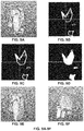
- FIG. 12A-12H are images created following steps of the pruning and smoothing method of FIG. 11 applied to 3D image of a mouse tibia, according to an illustrative embodiment of the present disclosure
- FIG. 13A-13D are example images illustrating results of 2-D slice-by-slice stereology operations performed automatically on a 3D image of a mouse tibia following central axis determination, according to an illustrative embodiment of the present disclosure.
- FIG. 14 is a block diagram of an example computing device and an example mobile computing device, for use in illustrative embodiments of the present disclosure
- FIG. 15 is a block diagram of an example computing environment, for use in illustrative embodiments of the present disclosure.
- an “image” for example, a 3-D image of mammal—includes any visual representation, such as a photo, a video frame, streaming video, as well as any electronic, digital or mathematical analogue of a photo, video frame, or streaming video.
- Any apparatus described herein includes a display for displaying an image or any other result produced by the processor.
- Any method described herein includes a step of displaying an image or any other result produced via the method.
- extracting or “extraction” of bone axes refers to the detection, segmentation, calculation, visualization, and the like, of axes (e.g., central axes) of bones.
- 3-D or “three-dimensional” with reference to an “image” means conveying information about three dimensions.
- a 3-D image may be rendered as a dataset in three dimensions and/or may be displayed as a set of two-dimensional representations, or as a three-dimensional representation.
- long bone means a bone of an extremity (e.g., of a mammal, e.g., mouse, rat, etc.) that has a length greater than the width (e.g., femur bone).
- a long bone is a bone of the legs, the arms, the hands, the feet, the fingers, the toes, or collar bones.
- a long bone is selected from the following: femora, tibiae, fibulae, humeri, radii, ulnae, metacarpals, metatarsals, phalanges, and clavicles (e.g., of collar bones).
- non-long bones include bones with partially circular shapes, e.g., the pelvic girdle.
- a “mask” is a graphical pattern that identifies a 2-D or 3-D region and is used to control the elimination or retention of portions of an image or other graphical pattern.
- the 3-D image is an in vivo image of an animal subject (e.g., a mammal such as a mouse).
- the 3-D image is an ex vivo image of a sample (e.g., bone sample) from an animal subject (e.g., a mammal such as a mouse).
- images can be acquired and/or processed by medical imaging devices such as CT scanners, microCT scanners, and the like. It should be understood that an image, such as a 3-D image, may be a single image or a set or series of multiple images.
- Central axes of bones can effectively encapsulate characteristics and data of bones, including, for example, spatial features, direction, orientation, and shape of a bone.
- the skeletal bones of animal subjects e.g., scanned by CT or microCT scanners
- the bone axes effectively represent the orientation of the bones relative to each other.
- the bone axes are also useful for determining bone directions (e.g., during computer-based analysis), as the axes carry quantitative structural information such as the spatial angle of the bone orientation.
- the 2-D planes perpendicular to the central axes are used for slice-by-slice stereology analysis of bones. By moving along the central axis and extracting 2-D planes normal to the central axis, 2-D slice-by-slice analyses such as stereology can be carried out as shown in FIG. 13 A-D, described in more detail below.
- Some example embodiments described herein relate to calculating and extracting central axes of skeletal bones to capture both the general and localized tangential directions of the bones.
- the calculation of central axes also identifies, among other things, the shape, form, and curvature of the bones. That is, the central axis represents a medial path that describes, among other things, the main center-line, shape, and orientation of a bone.
- bone central axes are not homogeneous solid objects with simple regular shapes; they can take arbitrary shapes and include hollow regions and holes with various densities and porosities.
- morphological skeletons of binary bone masks which reduce 3D regions into line sets, may not be represented by a single-branched axis, but rather, they may include multiple branches, especially at the distal ends, confounding traditional analysis.
- mere 3D skeletonization of a binary bone mask, or even a filled bone mask is found to be insufficient for extracting a central axis. As shown in FIG.
- skeletonization of solid objects results in multi-branched trees or graphs which cannot serve as a medial or central axis.
- Peripheral branches of skeletons only reflect certain regional spatial attributes of the solid object.
- 3D skeletonization reduces a solid object into a set of curved lines, only some of which carry information useful for calculation of the solid object's central axis; thus, in certain embodiments, further steps, as described herein, may be performed to extract the central axis of a solid object from its morphological skeleton in an accurate, automated, and reproducible way.
- bone central axes are extracted from morphological skeletons.
- Skeletons are generally defined for filled 2-D or 3-D binary objects.
- a skeleton may be represented and/or illustrated as a skeletal tree.
- the morphological skeleton is extracted by performing iterative thinning on the 3-D object binary mask. The process of extracting the morphological skeleton is referred to as skeletonization.
- skeletonization involves extracting the locus of the center of all maximally inscribed spheres in a 3-D object. Referring to FIG. 2 , the result of direct skeletonization of an elliptical prism annexed by conical sections is displayed.
- the skeleton is often comprised of a main branch that extends through the object, and a few minor branches that extend from the main branch to the boundary of the object, similar to the skeleton shown in FIG. 2 .
- results of direct 3-D skeletonization of bones are often not useful candidates for the central axis calculation and extraction due to two primary reasons.
- a skeletal bone is almost never a homogenously filled 3-D object, and its inner compartment (e.g., the trabeculae), is a porous structure distributed over the marrow.
- a direct 3-D skeletonization of the bone mask (without undergoing filling operations) would represent the medial tree spanning the cortical shell and trabecular network of the bone, rather than the morphological skeleton of the bone in its entirety including the cortical, trabecular, and marrow compartments.
- peripheral branches e.g., multi-branched segments extending into the conical sections 210 , 212
- the skeleton in its raw form, is not a single-branched central axis that represents the orientation and form of a 3-D object.
- the peripheral branches of the 3-D skeleton only carry localized structural information especially at the distal ends and are not useful in guiding and automating slice-by-slice measurements.
- FIG. 3 shows a 3-D image comprising multiple bones of a mammal, according to an exemplary embodiment. More specifically, FIG. 3 illustrates bones of the hind limb of a mouse (e.g., imaged by a microCT scanner) that are segmented into a femur, tibia, and patella, using splitting filters.
- a mouse e.g., imaged by a microCT scanner
- the bones 302 , 304 , 306 , 308 have been morphologically isolated and/or segmented from one another. Other bones have also been isolated, including the individual vertebrae 310 .
- Various common approaches may be taken toward isolating and/or segmenting the individual bones of the 3-D image, as shown in FIG. 3 , for example, the systems and methods described in U.S. patent application Ser. No. 14/812,483, filed Jul. 29, 2015, entitled, “Systems and Methods for Automated Segmentation of Individual Skeletal Bones in 3D Anatomical Images,” the text of which is incorporated herein by reference in its entirety.
- isolation and/or segmentation employs linear classification or regression, and a signal to noise ratio (S/N) corresponding to one or more features may be used to measure quality of classification or regression.
- S/N signal to noise ratio
- constraints for classification or regression are chosen empirically. For example, in some embodiments, constraints for classification or regression are chosen by running the same set of examples several times with varying constraints. Appropriate constraints may be chosen to strike a balance between accuracy and computing time in the isolation and/or segmentation algorithm chosen.
- FIG. 4 illustrates a flow chart for extracting a central bone axis from an isolated binary bone mask, according to an exemplary embodiment.
- a 3-D image or a series of 3-D images of the bones of a mammal is received, for example, from a CT or micro-CT scanner [ 402 ].
- the bone is morphologically isolated and/or segmented from a collection of bones [ 404 ], so that only the bone of interest (e.g., long bone) is analyzed. Morphological isolation and/or segmentation is described above in further detail with reference to FIG. 3 .
- a 3-D binary bone mask is a three-dimensional array comprising voxels in an included (e.g., binary true) or excluded (e.g., binary false) state.
- a voxel in the binary true state in the mask corresponds to a region containing bone tissue in the 3-D image of the bone(s).
- a voxel in a binary false state in the mask corresponds to an empty or non-bone tissue in the 3-D image.
- the binary bone mask represents at least the cortical and trabecular compartments of the bone(s).
- the binary bone mask is initially filled (e.g., the interior portion contents such as marrow) by binary true voxels (e.g., the binary bone mask represents a solid 3D bone volume composed of cortical, trabecular, and marrow compartments).
- binary true voxels e.g., the binary bone mask represents a solid 3D bone volume composed of cortical, trabecular, and marrow compartments.
- the binary mask of the bone is filled by morphological processing [ 408 ], which is described in further detail in the flowchart depicted in FIG. 6 .
- filling a 3-D object generally refers to the process of identifying the internal voxels (e.g., the internal sub-volume bounded by the surface) of the object and adding all of them to the binary bone mask (e.g., by changing their states to binary true).
- skeletonization is performed on the filled bone by iterative 3-D thinning [ 410 ], which is described in detail below.
- the skeleton is pruned (e.g., minor branches are removed) down to a single branch (e.g., the trunk) and smoothed [ 412 ], an illustrative method for which is described in detail in the flowchart depicted in FIG. 11 .
- these three steps yield a single-branched curve that follows the medial path of the bone, effectively identifying and isolating the central axis of the bone.
- the central bone axis 502 is obtained after the steps outlined in FIG. 4 are carried out, including pruning and smoothing the 3D morphological skeleton of the filled binary bone mask.
- FIG. 6 is a flowchart of a process for filling a binary mask of a bone (e.g., bone filling) using morphological processing, according to an exemplary embodiment.
- Bone filling is a step in extracting the central axis of a bone, e.g., step 408 of the method depicted in FIG. 4 .
- bone filling is performed by adding the internal compartment (e.g., marrow) of the bone to the bone mask.
- the presence of cracks or veins in the bone shell that connect the internal part or marrow of the bone to the background of the bone mask make bone filling more challenging.
- the internal compartment is morphologically connected to the background, and additional steps are required for accurate, robust detection of the internal compartment of the bone.
- the internal compartment is detected by performing a binary subtraction (e.g., an AND NOT operation) between dilated masks of the bone before and after morphological filling.
- dilation refers to expansion of an image, proportionately or disproportionately, along any axis or direction.
- the dilation is 3-D spherical dilation performed using a spherical structuring element of a size ranging from 3-5. Various methods of dilation may be employed.
- the internal compartment of the bone is obtained by dilating the result of this subtraction.
- border filling in the bone filling process is performed by applying 2-D filling to the border planes of the data-cube containing the bone image stack, as outlined in detail in the flowchart of FIG. 8 .
- a binary bone mask is generated [ 602 ] (e.g., retrieved) from a medical image such as a CT or a microCT scan of one or more bones of a mammal.
- a medical image such as a CT or a microCT scan of one or more bones of a mammal.
- the various bones contained in the image are automatically isolated and/or segmented (see FIG. 3 ).
- the binary bone mask generated in step 602 is herein referred to as Image0, although the method does not rely on any particular name being assigned to any image.
- the binary bone mask (Image0) is dilated, by a spherical structuring element, e.g., of size 3-10 depending on the metric voxel dimensions of the image, and the dilated binary bone mask is stored as Image1 [ 604 ].
- a spherical structuring element e.g., of size 3-10 depending on the metric voxel dimensions of the image
- the borders of Image1 are then identified and filled [ 606 ].
- Morphological holes e.g., gaps and/or discontinuities
- Border filling is described in more detail below with reference to FIG. 8 .
- 3D binary erosion is performed [ 610 ] to produce the filled bone mask [ 622 ].
- the result of the 3D hole filling and border filling operations is stored as Image2.
- Image1 is then subtracted from Image2 [ 610 ], resulting in a mask effectively representing the location of filled holes and cracks.
- small spots defined as connected components with volumes smaller than empirically determined bounds, are removed from the resulting mask and the image is again dilated, and stored as Image3.
- a new image is generated by combining Image0 with Image3, resulting in the binary bone mask of Image0 superimposed with the filled holes represented by Image3.
- the borders of the resulting image (Image0+Image3) are filled and subsequently the holes of the 3D image are filled.
- the holes are identified as the empty or binary false voxels located in the internal compartment of the dilated bone mask (morphologically disconnected from the background image by the dilated bone mask).
- the holes are filled by being added to the bone mask (or their voxel values being updated to 1 or binary true).
- FIGS. 7A-7E show the results of the steps described in reference to FIG. 6 .
- FIG. 7A depicts two views—external and cut-away—of the result of the binary bone mask, step 602 of the method of FIG. 6 .
- FIG. 7B depicts the result of 3D binary dilation, step 604 of the method of FIG. 6 .
- FIG. 7C depicts the result of border filling operations, step 606 of the method of FIG. 6 .
- FIG. 7D depicts the result of morphological hole filling, step 608 of the method of FIG. 6 .
- FIG. 7E depicts the filled bone mask resulting from 3D binary erosion, step 610 of the method of FIG. 6 .
- FIG. 8 illustrates a process for performing border filling, according to an exemplary embodiment.
- border filling is performed during the process of generating a binary bone mask (e.g., FIG. 6 ). Border filling is performed on an unprocessed or processed bone mask (e.g., a dilated bone image resulting from step 604 of FIG. 6 ).
- image data (e.g., of the binary bone mask) is represented digitally as one or more data-cubes.
- a data-cube comprises a 3D array of values corresponding to voxels in the 3-D bone mask including twelve edges and eight vertices, each of the vertices being associated with three edges. Each edge of the data-cube is associated with two faces.
- a first data-cube vertex is selected from the eight vertices [ 804 ], an example of which is shown in FIG. 9A .
- the selected vertex is checked to ensure all three edges connected to the vertex contain voxels belonging to the binary mask [ 806 ]. If an edge connected to a vertex contains a binary mask voxel, it is associated with and/or assigned a true (e.g., binary true) state. If all of the edges connected to the selected vertex are associated with true voxels, the vertex check is satisfied. Otherwise, if the vertex check does not pass, the next vertex is selected. If the vertex passes the voxel check, a 2-D image is formed by concatenating the three faces connected to the vertex with an all-zero face as a quadrant [ 808 ], an example of which is shown in FIG. 9B .
- Pixels with binary true values bordering the all-zero quadrant are then connected diagonally by updating the values of the corresponding pixels of the all-zero quadrant to binary true [ 810 ], as depicted in FIG. 9C .
- Morphological holes in the resulting concatenated 2-D image are then filled and the filled surfaces are mapped back to the three corresponding faces of the data-cube [ 812 ], as depicted in FIG. 9D (2-D image) and FIGS. 9E and 9F (two views of the resulting data-cube).
- step 818 the method proceeds to step 818 . Otherwise, the method returns to select the next vertex in the data-cube, in step 804 .
- a first data-cube edge is selected [ 818 ]. The edge is checked to ensure both of the faces connected to the edge and the edge itself contain binary true voxels [ 820 ]. If the edge check is passed (e.g., edge is associated with true voxels), a 2-D image is formed from concatenating the two faces connected to edge [ 822 ]. Otherwise the next data-cube edge is selected as in step 818 .
- Morphological holes in the 2-D image are filled and the filled surfaces are mapped back to the two corresponding faces of the data cube [ 824 ]. If all edges have been completed [ 826 ], the method continues to step 828 , otherwise the next edge is selected. After all edges are completed, the holes on each individual face of the data-cube are filled [ 830 ], thereby generating a border-filled bone mask. The border-filled bone mask is stored in memory [ 828 ].
- identifying a central bone axis also includes a step of 3-D thinning.
- 3-D thinning is described in more detail in Building Skeleton Models via 3-D medial Surface/Axis Thinning Algorithms (Lee, T. C., Graphical Models and Image Processing, Vol. 56, No. 6, November, pp. 462-478, 1994), which is incorporated herein by reference in its entirety.
- 3-D thinning shrinks or reduces solid objects, areas, or volumes, such as a filled 3-D object (e.g., bone) to a morphological skeleton (see FIG. 10 ), with major and minor branches.
- the skeleton (or the medial surface) of a structure is the locus of the center of all maximally inscribed spheres of the object in 3-D space (e.g., Euclidean space) where each of the spheres touch the boundary at more than one point.
- a distance transformation is used to thin the 3-D image.
- border points are repetitively deleted under topological and geometrical constraints until a smaller set of connected points is acquired.
- the 3-D skeleton substantially represents or is an approximation of the “true” skeleton in the 3-D Euclidean space.
- level set marching approaches are performed.
- the iterative deletion of border points provides 3-D thinning while maintaining topological properties of the image being thinned.
- each thinning iteration is divided into subcycles according to the type of border point (e.g., north, south, west, east, up, bottom).
- the border points that are deleted are restricted based on topological and geometric constraints, for example, to avoid undesired object separation or elimination in the image.
- medial surface thinning (MST) and/or medial axis thinning (MAT) may be used as geometric constraints of the border deletion process of a 3-D thinning operation. That is, MST is used to identify surface points that are not deleted during thinning.
- medial surface thinning identifies surfaces that are approximately located to a center line.
- MAT differs from MST in that the extracted skeleton consists of arcs and/or curves instead of surfaces that approximate the center line.
- MST and MAT are both described in further detail in Building Skeleton Models via 3-D medial Surface/Axis Thinning Algorithms (Lee, T. C., Graphical Models and Image Processing, Vol. 56, No. 6, November, pp. 462-478, 1994), which is incorporated herein by reference in its entirety.
- FIG. 10 shows a 3-D skeletonization of a filled bone mask from the tibia of a mouse, according to an exemplary embodiment.
- the skeleton 902 may be further pruned and smoothed, as shown below with reference to FIG. 11 .
- FIG. 11 illustrates a process [ 1100 ] of pruning and smoothing a skeleton to yield the central axis of the bone, according to an exemplary embodiment.
- a binary skeleton mask is retrieved [ 1102 ].
- a particular path e.g., a main or central path
- the centerline tree of the skeleton for example, via the method described in “TEASAR: tree-structure extraction algorithm for accurate and robust skeletons Sato, M.; Bitter, I.; Bender, M. A.; Kaufman, A. E.; Nakajima, M. Computer Graphics and Applications, 2000. Proceedings.
- the centerline tree of the skeleton is found using the TEASAR algorithm referenced above, which includes (1) reading binary segmented voxels inside the object; (2) cropping the volume to just the object; (3) computing the distance from boundary field (DBF); (4) computing the distance from any voxel field (DAF); (5) computing the penalized distance from root voxel field (PDRF); (6) finding the farthest PDRF voxel labeled as inside; (7) extracting the shortest path from that voxel to the root; (8) labeling all the voxels near the path as ‘used to be inside’; and (9) repeating steps 6 to 8 until no inside voxels remain.
- the TEASAR algorithm referenced above, which includes (1) reading binary segmented voxels inside the object; (2) cropping the volume to just the object; (3) computing the distance from boundary field (DBF); (4) computing the distance from any voxel field (DAF); (5) computing the penalized distance from root voxel
- the minor branches of the skeleton are removed from the identified main path, thus reducing the skeleton to a single branch.
- the pruned branch is further smoothed by point averaging [ 1108 ].
- the end result of this step is the bone central axis [ 1110 ], an example of which is illustrated in FIG. 5 at reference [ 502 ].
- FIG. 12A-12H are images created following steps of the pruning and smoothing method of FIG. 11 , as applied to the tibia ( FIGS. 12A-12D ) and femur ( FIGS. 12E-12H ) of a mouse scanned by a microCT imaging platform after bone segmentation as shown in FIG. 3 . From left to right, the images show the bone mask ( FIGS. 12A / 12 E), the result of the skeletonization step [ 1104 ] ( FIGS. 12B / 12 F), the result of the pruning step [ 1106 ] ( FIGS. 12C / 12 G), and the result of the smoothing step [ 1108 ] ( FIGS. 12D / 12 H), thereby producing the central axis for the tibia and femur.
- the identified central axis of the bone is used to quantify structural characteristics (e.g., features) of the bone, such as the bone's shape, form, localized tangential directions, curvature, and the like. These characteristics may be used, in turn, to characterize the bone, for example, by identifying abnormalities, identifying the bone as a specific bone, and the like.
- the identified central axis is used to render images of the bone or the set of bones with which the bone is associated. It should be understood that the characteristics of a bone, identified using the bone's central axis, can be used, for example, for other imaging (e.g., rendering), diagnostics, and therapeutic purposes, as well as for other applications.
- the identified central axis of the bone is used for stereological measurements and slice-by-slice studies of the bone.
- FIG. 13A-13D are example images illustrating results of 2-D slice-by-slice stereology operations performed accurately and automatically following central axis determination. The planes perpendicular to the central axis are used to create 2-D image slices of the bone cross-section. Parameters such as average cortical thickness can then be calculated from these 2-D slices automatically.
- FIG. 13A shows a mouse tibia 1300 following determination of the bone central axis per methods described herein. Planes 1302 , 1306 , and 1310 are identified.
- FIGS. 13B-13D Images of 2-D cross-sections at these planes are obtained, e.g., images of FIGS. 13B-13D .
- FIG. 13B corresponds to plane 1302
- FIG. 13C corresponds to plane 1306
- FIG. 13D corresponds to plane 1310 .
- various bone properties can be determined, for example, average cortical (shell) thickness. Any number of cross-sections may be taken. In the case shown in FIG. 13 , the average cortical thickness was automatically determined to be 3.98 voxels or 198 microns.
- the method disclosed herein provides an automated, robust way of obtaining this information directly from a scan (e.g., micro-CT scan), thereby eliminating operator error and variability due to “by hand” measurements.
- certain embodiments of the procedures described herein relate to extracting the central axis of a bone to guide stereological measurements or capture, for example, of the direction, overall shape, and spatial characteristics of the bone.
- Various other embodiments utilize the image processing methods described herein, including procedures such as border filling, bone filling, and pruning/smoothing, for other applications.
- the image processing methods described herein may be used in bone segmentation/separation using morphological separation approaches such as watershed.
- the morphological separation is performed on filled bones rather than the original bone masks.
- border and bone filling are also useful in segmenting the cortical and trabecular compartment of a bone, for example.
- FIG. 14 shows an illustrative network environment 1400 for use in the methods and systems described herein.
- the cloud computing environment 1400 may include one or more resource providers 1402 a , 1402 b , 1402 c (collectively, 1402 ).
- Each resource provider 1402 may include computing resources.
- computing resources may include any hardware and/or software used to process data.
- computing resources may include hardware and/or software capable of executing algorithms, computer programs, and/or computer applications.
- exemplary computing resources may include application servers and/or databases with storage and retrieval capabilities.
- Each resource provider 1402 may be connected to any other resource provider 1402 in the cloud computing environment 1400 .
- the resource providers 1402 may be connected over a computer network 1408 .
- Each resource provider 1402 may be connected to one or more computing device 1404 a , 1404 b , 1404 c (collectively, 1404 ), over the computer network 1408 .
- the cloud computing environment 1400 may include a resource manager 1406 .
- the resource manager 1406 may be connected to the resource providers 1402 and the computing devices 1404 over the computer network 1408 .
- the resource manager 1406 may facilitate the provision of computing resources by one or more resource providers 1402 to one or more computing devices 1404 .
- the resource manager 1406 may receive a request for a computing resource from a particular computing device 1404 .
- the resource manager 1406 may identify one or more resource providers 1402 capable of providing the computing resource requested by the computing device 1404 .
- the resource manager 1406 may select a resource provider 1402 to provide the computing resource.
- the resource manager 1406 may facilitate a connection between the resource provider 1402 and a particular computing device 1404 .
- the resource manager 1406 may establish a connection between a particular resource provider 1402 and a particular computing device 1404 . In some implementations, the resource manager 1406 may redirect a particular computing device 1404 to a particular resource provider 1402 with the requested computing resource.
- FIG. 15 shows an example of a computing device 1500 and a mobile computing device 1550 that can be used in the methods and systems described in this disclosure.
- the computing device 1500 is intended to represent various forms of digital computers, such as laptops, desktops, workstations, personal digital assistants, servers, blade servers, mainframes, and other appropriate computers.
- the mobile computing device 1550 is intended to represent various forms of mobile devices, such as personal digital assistants, cellular telephones, smart-phones, and other similar computing devices.
- the components shown here, their connections and relationships, and their functions, are meant to be examples only, and are not meant to be limiting.
- the computing device 1500 includes a processor 1502 , a memory 1504 , a storage device 1506 , a high-speed interface 1508 connecting to the memory 1504 and multiple high-speed expansion ports 1510 , and a low-speed interface 1512 connecting to a low-speed expansion port 1514 and the storage device 1506 .
- Each of the processor 1502 , the memory 1504 , the storage device 1506 , the high-speed interface 1508 , the high-speed expansion ports 1510 , and the low-speed interface 1512 are interconnected using various busses, and may be mounted on a common motherboard or in other manners as appropriate.
- the processor 1502 can process instructions for execution within the computing device 1500 , including instructions stored in the memory 1504 or on the storage device 1506 to display graphical information for a GUI on an external input/output device, such as a display 1516 coupled to the high-speed interface 1508 .
- an external input/output device such as a display 1516 coupled to the high-speed interface 1508 .
- multiple processors and/or multiple buses may be used, as appropriate, along with multiple memories and types of memory.
- multiple computing devices may be connected, with each device providing portions of the necessary operations (e.g., as a server bank, a group of blade servers, or a multi-processor system).
- the memory 1504 stores information within the computing device 1500 .
- the memory 1504 is a volatile memory unit or units.
- the memory 1504 is a non-volatile memory unit or units.
- the memory 1504 may also be another form of computer-readable medium, such as a magnetic or optical disk.
- the storage device 1506 is capable of providing mass storage for the computing device 1500 .
- the storage device 1506 may be or contain a computer-readable medium, such as a floppy disk device, a hard disk device, an optical disk device, or a tape device, a flash memory or other similar solid state memory device, or an array of devices, including devices in a storage area network or other configurations.
- Instructions can be stored in an information carrier.
- the instructions when executed by one or more processing devices (for example, processor 1502 ), perform one or more methods, such as those described above.
- the instructions can also be stored by one or more storage devices such as computer- or machine-readable mediums (for example, the memory 1504 , the storage device 1506 , or memory on the processor 1502 ).
- the high-speed interface 1508 manages bandwidth-intensive operations for the computing device 1500 , while the low-speed interface 1512 manages lower bandwidth-intensive operations. Such allocation of functions is an example only.
- the high-speed interface 1508 is coupled to the memory 1504 , the display 1516 (e.g., through a graphics processor or accelerator), and to the high-speed expansion ports 1510 , which may accept various expansion cards (not shown).
- the low-speed interface 1512 is coupled to the storage device 1506 and the low-speed expansion port 1514 .
- the low-speed expansion port 1514 which may include various communication ports (e.g., USB, Bluetooth®, Ethernet, wireless Ethernet) may be coupled to one or more input/output devices, such as a keyboard, a pointing device, a scanner, or a networking device such as a switch or router, e.g., through a network adapter.
- input/output devices such as a keyboard, a pointing device, a scanner, or a networking device such as a switch or router, e.g., through a network adapter.
- the computing device 1500 may be implemented in a number of different forms, as shown in the figure. For example, it may be implemented as a standard server 1520 , or multiple times in a group of such servers. In addition, it may be implemented in a personal computer such as a laptop computer 1522 . It may also be implemented as part of a rack server system 1524 . Alternatively, components from the computing device 1500 may be combined with other components in a mobile device (not shown), such as a mobile computing device 1550 . Each of such devices may contain one or more of the computing device 1500 and the mobile computing device 1550 , and an entire system may be made up of multiple computing devices communicating with each other.
- the mobile computing device 1550 includes a processor 1552 , a memory 1564 , an input/output device such as a display 1554 , a communication interface 1566 , and a transceiver 1568 , among other components.
- the mobile computing device 1550 may also be provided with a storage device, such as a micro-drive or other device, to provide additional storage.
- a storage device such as a micro-drive or other device, to provide additional storage.
- Each of the processor 1552 , the memory 1564 , the display 1554 , the communication interface 1566 , and the transceiver 1568 are interconnected using various buses, and several of the components may be mounted on a common motherboard or in other manners as appropriate.
- the processor 1552 can execute instructions within the mobile computing device 1550 , including instructions stored in the memory 1564 .
- the processor 1552 may be implemented as a chipset of chips that include separate and multiple analog and digital processors.
- the processor 1552 may provide, for example, for coordination of the other components of the mobile computing device 1550 , such as control of user interfaces, applications run by the mobile computing device 1550 , and wireless communication by the mobile computing device 1550 .
- the processor 1552 may communicate with a user through a control interface 1558 and a display interface 1556 coupled to the display 1554 .
- the display 1554 may be, for example, a TFT (Thin-Film-Transistor Liquid Crystal Display) display or an OLED (Organic Light Emitting Diode) display, or other appropriate display technology.
- the display interface 1556 may comprise appropriate circuitry for driving the display 1554 to present graphical and other information to a user.
- the control interface 1558 may receive commands from a user and convert them for submission to the processor 1552 .
- an external interface 1562 may provide communication with the processor 1552 , so as to enable near area communication of the mobile computing device 1550 with other devices.
- the external interface 1562 may provide, for example, for wired communication in some implementations, or for wireless communication in other implementations, and multiple interfaces may also be used.
- the memory 1564 stores information within the mobile computing device 1550 .
- the memory 1564 can be implemented as one or more of a computer-readable medium or media, a volatile memory unit or units, or a non-volatile memory unit or units.
- An expansion memory 1574 may also be provided and connected to the mobile computing device 1550 through an expansion interface 1572 , which may include, for example, a SIMM (Single In Line Memory Module) card interface.
- SIMM Single In Line Memory Module
- the expansion memory 1574 may provide extra storage space for the mobile computing device 1550 , or may also store applications or other information for the mobile computing device 1550 .
- the expansion memory 1574 may include instructions to carry out or supplement the processes described above, and may include secure information also.
- the expansion memory 1574 may be provided as a security module for the mobile computing device 1550 , and may be programmed with instructions that permit secure use of the mobile computing device 1550 .
- secure applications may be provided via the SIMM cards, along with additional information, such as placing identifying information on the SIMM card in a non-hackable manner.
- the memory may include, for example, flash memory and/or NVRAM memory (non-volatile random access memory), as discussed below.
- instructions are stored in an information carrier and, when executed by one or more processing devices (for example, processor 1552 ), perform one or more methods, such as those described above.
- the instructions can also be stored by one or more storage devices, such as one or more computer- or machine-readable mediums (for example, the memory 1564 , the expansion memory 1574 , or memory on the processor 1552 ).
- the instructions can be received in a propagated signal, for example, over the transceiver 1568 or the external interface 1562 .
- the mobile computing device 1550 may communicate wirelessly through the communication interface 1566 , which may include digital signal processing circuitry where necessary.
- the communication interface 1566 may provide for communications under various modes or protocols, such as GSM voice calls (Global System for Mobile communications), SMS (Short Message Service), EMS (Enhanced Messaging Service), or MMS messaging (Multimedia Messaging Service), CDMA (code division multiple access), TDMA (time division multiple access), PDC (Personal Digital Cellular), WCDMA (Wideband Code Division Multiple Access), CDMA2000, or GPRS (General Packet Radio Service), among others.
- GSM voice calls Global System for Mobile communications
- SMS Short Message Service
- EMS Enhanced Messaging Service
- MMS messaging Multimedia Messaging Service
- CDMA code division multiple access
- TDMA time division multiple access
- PDC Personal Digital Cellular
- WCDMA Wideband Code Division Multiple Access
- CDMA2000 Code Division Multiple Access
- GPRS General Packet Radio Service
- a GPS (Global Positioning System) receiver module 1570 may provide additional navigation- and location-related wireless data to the mobile computing device 1550 , which may be used as appropriate by applications running on the mobile computing device 1550 .
- the mobile computing device 1550 may also communicate audibly using an audio codec 1560 , which may receive spoken information from a user and convert it to usable digital information.
- the audio codec 1560 may likewise generate audible sound for a user, such as through a speaker, e.g., in a handset of the mobile computing device 1550 .
- Such sound may include sound from voice telephone calls, may include recorded sound (e.g., voice messages, music files, etc.) and may also include sound generated by applications operating on the mobile computing device 1550 .
- the mobile computing device 1550 may be implemented in a number of different forms, as shown in the figure. For example, it may be implemented as a cellular telephone 1580 . It may also be implemented as part of a smart-phone 1582 , personal digital assistant, or other similar mobile device.
- implementations of the systems and techniques described here can be realized in digital electronic circuitry, integrated circuitry, specially designed ASICs (application specific integrated circuits), computer hardware, firmware, software, and/or combinations thereof.
- ASICs application specific integrated circuits
- These various implementations can include implementation in one or more computer programs that are executable and/or interpretable on a programmable system including at least one programmable processor, which may be special or general purpose, coupled to receive data and instructions from, and to transmit data and instructions to, a storage system, at least one input device, and at least one output device.
- machine-readable medium and computer-readable medium refer to any computer program product, apparatus and/or device (e.g., magnetic discs, optical disks, memory, Programmable Logic Devices (PLDs)) used to provide machine instructions and/or data to a programmable processor, including a machine-readable medium that receives machine instructions as a machine-readable signal.
- machine-readable signal refers to any signal used to provide machine instructions and/or data to a programmable processor.
- the systems and techniques described here can be implemented on a computer having a display device (e.g., a CRT (cathode ray tube) or LCD (liquid crystal display) monitor) for displaying information to the user and a keyboard and a pointing device (e.g., a mouse or a trackball) by which the user can provide input to the computer.
- a display device e.g., a CRT (cathode ray tube) or LCD (liquid crystal display) monitor
- a keyboard and a pointing device e.g., a mouse or a trackball
- Other kinds of devices can be used to provide for interaction with a user as well; for example, feedback provided to the user can be any form of sensory feedback (e.g., visual feedback, auditory feedback, or tactile feedback); and input from the user can be received in any form, including acoustic, speech, or tactile input.
- the systems and techniques described here can be implemented in a computing system that includes a back end component (e.g., as a data server), or that includes a middleware component (e.g., an application server), or that includes a front end component (e.g., a client computer having a graphical user interface or a Web browser through which a user can interact with an implementation of the systems and techniques described here), or any combination of such back end, middleware, or front end components.
- the components of the system can be interconnected by any form or medium of digital data communication (e.g., a communication network). Examples of communication networks include a local area network (LAN), a wide area network (WAN), and the Internet.
- LAN local area network
- WAN wide area network
- the Internet the global information network
- the computing system can include clients and servers.
- a client and server are generally remote from each other and typically interact through a communication network.
- the relationship of client and server arises by virtue of computer programs running on the respective computers and having a client-server relationship to each other.
Landscapes
- Health & Medical Sciences (AREA)
- Engineering & Computer Science (AREA)
- Life Sciences & Earth Sciences (AREA)
- Medical Informatics (AREA)
- Physics & Mathematics (AREA)
- General Health & Medical Sciences (AREA)
- Nuclear Medicine, Radiotherapy & Molecular Imaging (AREA)
- Radiology & Medical Imaging (AREA)
- Public Health (AREA)
- Pathology (AREA)
- Biomedical Technology (AREA)
- Surgery (AREA)
- Optics & Photonics (AREA)
- High Energy & Nuclear Physics (AREA)
- Heart & Thoracic Surgery (AREA)
- Molecular Biology (AREA)
- Biophysics (AREA)
- Animal Behavior & Ethology (AREA)
- Theoretical Computer Science (AREA)
- Veterinary Medicine (AREA)
- Computer Vision & Pattern Recognition (AREA)
- General Physics & Mathematics (AREA)
- Dentistry (AREA)
- Quality & Reliability (AREA)
- Pulmonology (AREA)
- Orthopedic Medicine & Surgery (AREA)
- Oral & Maxillofacial Surgery (AREA)
- Physiology (AREA)
- Geometry (AREA)
- Data Mining & Analysis (AREA)
- Databases & Information Systems (AREA)
- Epidemiology (AREA)
- Primary Health Care (AREA)
- Apparatus For Radiation Diagnosis (AREA)
- Image Processing (AREA)
Abstract
Description
Claims (24)
Priority Applications (1)
| Application Number | Priority Date | Filing Date | Title |
|---|---|---|---|
| US16/724,722 US11219424B2 (en) | 2016-03-25 | 2019-12-23 | Systems and methods for characterizing a central axis of a bone from a 3D anatomical image |
Applications Claiming Priority (3)
| Application Number | Priority Date | Filing Date | Title |
|---|---|---|---|
| US15/081,788 US10136869B2 (en) | 2016-03-25 | 2016-03-25 | Systems and methods for characterizing a central axis of a bone from a 3D anatomical image |
| US16/155,943 US10548553B2 (en) | 2016-03-25 | 2018-10-10 | Systems and methods for characterizing a central axis of a bone from a 3D anatomical image |
| US16/724,722 US11219424B2 (en) | 2016-03-25 | 2019-12-23 | Systems and methods for characterizing a central axis of a bone from a 3D anatomical image |
Related Parent Applications (1)
| Application Number | Title | Priority Date | Filing Date |
|---|---|---|---|
| US16/155,943 Continuation US10548553B2 (en) | 2016-03-25 | 2018-10-10 | Systems and methods for characterizing a central axis of a bone from a 3D anatomical image |
Publications (2)
| Publication Number | Publication Date |
|---|---|
| US20200178919A1 US20200178919A1 (en) | 2020-06-11 |
| US11219424B2 true US11219424B2 (en) | 2022-01-11 |
Family
ID=59896290
Family Applications (3)
| Application Number | Title | Priority Date | Filing Date |
|---|---|---|---|
| US15/081,788 Active 2036-10-30 US10136869B2 (en) | 2016-03-25 | 2016-03-25 | Systems and methods for characterizing a central axis of a bone from a 3D anatomical image |
| US16/155,943 Active US10548553B2 (en) | 2016-03-25 | 2018-10-10 | Systems and methods for characterizing a central axis of a bone from a 3D anatomical image |
| US16/724,722 Active 2036-05-18 US11219424B2 (en) | 2016-03-25 | 2019-12-23 | Systems and methods for characterizing a central axis of a bone from a 3D anatomical image |
Family Applications Before (2)
| Application Number | Title | Priority Date | Filing Date |
|---|---|---|---|
| US15/081,788 Active 2036-10-30 US10136869B2 (en) | 2016-03-25 | 2016-03-25 | Systems and methods for characterizing a central axis of a bone from a 3D anatomical image |
| US16/155,943 Active US10548553B2 (en) | 2016-03-25 | 2018-10-10 | Systems and methods for characterizing a central axis of a bone from a 3D anatomical image |
Country Status (1)
| Country | Link |
|---|---|
| US (3) | US10136869B2 (en) |
Families Citing this family (11)
| Publication number | Priority date | Publication date | Assignee | Title |
|---|---|---|---|---|
| CA2978500C (en) * | 2015-03-04 | 2022-07-05 | Institute of Mineral Resources, Chinese Academy of Geological Sciences | Method for automatically extracting tectonic framework of potential field data |
| CN106127777B (en) * | 2016-06-27 | 2017-08-29 | 中山大学 | A kind of three dimensions crack separation identification and characterizing method |
| US10687899B1 (en) * | 2016-07-05 | 2020-06-23 | Smith & Nephew, Inc. | Bone model correction angle determination |
| US10813614B2 (en) | 2017-05-24 | 2020-10-27 | Perkinelmer Health Sciences, Inc. | Systems and methods for automated analysis of heterotopic ossification in 3D images |
| US10768431B2 (en) | 2017-12-20 | 2020-09-08 | Aperture In Motion, LLC | Light control devices and methods for regional variation of visual information and sampling |
| EP3564906A1 (en) * | 2018-05-04 | 2019-11-06 | Siemens Healthcare GmbH | Method for generating image data in a computer tomography unit, image generating computer, computer tomography unit, computer program product and computer-readable medium |
| FI20195977A1 (en) | 2019-11-15 | 2021-05-16 | Disior Oy | Arrangement and method for provision of enhanced two-dimensional imaging data |
| CN114444313B (en) * | 2022-01-29 | 2022-12-06 | 李危石 | Biological tissue recognition system |
| US12373955B2 (en) * | 2022-07-25 | 2025-07-29 | Dell Products L.P. | System and method for storage management of images |
| US12423938B2 (en) | 2022-07-25 | 2025-09-23 | Dell Products L.P. | System and method for identifying auxiliary areas of interest for image based on focus indicators |
| CN120853167A (en) * | 2025-09-22 | 2025-10-28 | 中国农业大学 | Seed multimodal microscopic image acquisition method, device, equipment and storage medium |
Citations (21)
| Publication number | Priority date | Publication date | Assignee | Title |
|---|---|---|---|---|
| US20050163358A1 (en) | 2004-01-26 | 2005-07-28 | Thomas Moeller | System and method for automatic bone extraction from a medical image |
| JP2006102353A (en) | 2004-10-08 | 2006-04-20 | Toshiba Corp | Joint motion analysis device, joint motion analysis method, and joint motion analysis program |
| US20070031019A1 (en) | 2005-07-28 | 2007-02-08 | David Lesage | System and method for coronary artery segmentation of cardiac CT volumes |
| JP2008093229A (en) | 2006-10-13 | 2008-04-24 | Univ Of Tokyo | Knee joint diagnosis support method, apparatus and program |
| US20080107318A1 (en) | 2006-11-03 | 2008-05-08 | Siemens Corporation Research, Inc. | Object Centric Data Reformation With Application To Rib Visualization |
| US20080273777A1 (en) * | 2005-10-21 | 2008-11-06 | Vincent Luboz | Methods And Apparatus For Segmentation And Reconstruction For Endovascular And Endoluminal Anatomical Structures |
| US7539332B1 (en) | 2003-09-19 | 2009-05-26 | Compumed, Inc. | Method and system for automatically identifying regions of trabecular bone tissue and cortical bone tissue of a target bone from a digital radiograph image |
| WO2009101560A2 (en) | 2008-02-15 | 2009-08-20 | Koninklijke Philips Electronics N.V. | Apparatus for segmenting an object comprising sub-objects |
| US20100128954A1 (en) | 2008-11-25 | 2010-05-27 | Algotec Systems Ltd. | Method and system for segmenting medical imaging data according to a skeletal atlas |
| US20120143037A1 (en) | 2009-04-07 | 2012-06-07 | Kayvan Najarian | Accurate Pelvic Fracture Detection for X-Ray and CT Images |
| US20120224758A1 (en) | 2009-10-07 | 2012-09-06 | Cambridge Enterprise Limited | Image data processing systems |
| US8306305B2 (en) * | 2005-03-17 | 2012-11-06 | Algotec Systems Ltd. | Bone segmentation |
| US20130039592A1 (en) | 2003-03-25 | 2013-02-14 | Imatx, Inc. | Methods for the compensation of imaging technique in the processing of radiographic images |
| US20130163836A1 (en) | 2011-12-23 | 2013-06-27 | Stmicroelectronics S.R.L. | Computing the mass of an object |
| JP2013172792A (en) | 2012-02-24 | 2013-09-05 | Toshiba Corp | Medical image diagnostic apparatus |
| US20130272594A1 (en) | 2010-12-21 | 2013-10-17 | Elazar Zelzer | Method and system of imaging and/or diagnosing a bone from a reconstructed volume image |
| JP2015066311A (en) | 2013-09-30 | 2015-04-13 | 国立大学法人徳島大学 | Image processor, image processing method, program for controlling image processor, and recording medium |
| US9192348B2 (en) | 2014-01-23 | 2015-11-24 | Perkinelmer Cellular Technologies Germany Gmbh | Method and system for automated detection of tissue interior to a mammalian ribcage from an in vivo image |
| US20160038124A1 (en) | 2012-09-26 | 2016-02-11 | Hitachi Aloka Medical, Ltd. | Ultrasound diagnostic apparatus and ultrasound three-dimensional image creation method |
| US20160242852A1 (en) * | 2013-10-09 | 2016-08-25 | Persimio Ltd | Automated patient-specific method for biomechanical analysis of bone |
| US20170032518A1 (en) | 2015-07-29 | 2017-02-02 | Perkinelmer Health Sciences, Inc. | Systems and methods for automated segmentation of individual skeletal bones in 3d anatomical images |
Family Cites Families (5)
| Publication number | Priority date | Publication date | Assignee | Title |
|---|---|---|---|---|
| JP3229200B2 (en) | 1996-05-07 | 2001-11-12 | 帝人株式会社 | Bone measurement method |
| JP5264090B2 (en) | 2007-03-08 | 2013-08-14 | 株式会社日立メディコ | Image processing device |
| RU2342077C1 (en) | 2007-08-08 | 2008-12-27 | Государственное образовательное учреждение высшего профессионального образования "БАШКИРСКИЙ ГОСУДАРСТВЕННЫЙ МЕДИЦИНСКИЙ УНИВЕРСИТЕТ Федерального Агентства по здравоохранению и социальному развитию" (ГОУ ВПО БГМУ РОСЗДРАВА) | Method of three-dimensional visualisation of long tubular bones in case of diaphyseal fractures |
| JP6741750B2 (en) | 2015-07-29 | 2020-08-19 | ペルキネルマー ヘルス サイエンシーズ, インコーポレイテッド | System and method for automated segmentation of individual skeletal bones in 3D anatomical images |
| RU2703699C1 (en) | 2016-03-25 | 2019-10-21 | Перкинэлмер Хелс Сайансес, Инк. | Systems and methods for determining characteristics of a central bone axis based on a three-dimensional anatomical image |
-
2016
- 2016-03-25 US US15/081,788 patent/US10136869B2/en active Active
-
2018
- 2018-10-10 US US16/155,943 patent/US10548553B2/en active Active
-
2019
- 2019-12-23 US US16/724,722 patent/US11219424B2/en active Active
Patent Citations (22)
| Publication number | Priority date | Publication date | Assignee | Title |
|---|---|---|---|---|
| US20130039592A1 (en) | 2003-03-25 | 2013-02-14 | Imatx, Inc. | Methods for the compensation of imaging technique in the processing of radiographic images |
| US7539332B1 (en) | 2003-09-19 | 2009-05-26 | Compumed, Inc. | Method and system for automatically identifying regions of trabecular bone tissue and cortical bone tissue of a target bone from a digital radiograph image |
| US20050163358A1 (en) | 2004-01-26 | 2005-07-28 | Thomas Moeller | System and method for automatic bone extraction from a medical image |
| JP2006102353A (en) | 2004-10-08 | 2006-04-20 | Toshiba Corp | Joint motion analysis device, joint motion analysis method, and joint motion analysis program |
| US8306305B2 (en) * | 2005-03-17 | 2012-11-06 | Algotec Systems Ltd. | Bone segmentation |
| US20070031019A1 (en) | 2005-07-28 | 2007-02-08 | David Lesage | System and method for coronary artery segmentation of cardiac CT volumes |
| US20080273777A1 (en) * | 2005-10-21 | 2008-11-06 | Vincent Luboz | Methods And Apparatus For Segmentation And Reconstruction For Endovascular And Endoluminal Anatomical Structures |
| JP2008093229A (en) | 2006-10-13 | 2008-04-24 | Univ Of Tokyo | Knee joint diagnosis support method, apparatus and program |
| US20080107318A1 (en) | 2006-11-03 | 2008-05-08 | Siemens Corporation Research, Inc. | Object Centric Data Reformation With Application To Rib Visualization |
| WO2009101560A2 (en) | 2008-02-15 | 2009-08-20 | Koninklijke Philips Electronics N.V. | Apparatus for segmenting an object comprising sub-objects |
| US20100128954A1 (en) | 2008-11-25 | 2010-05-27 | Algotec Systems Ltd. | Method and system for segmenting medical imaging data according to a skeletal atlas |
| EP2194505B1 (en) | 2008-11-25 | 2015-03-11 | Algotec Systems Ltd. | Method and apparatus for segmenting spine and aorta in a medical image according to a skeletal atlas |
| US20120143037A1 (en) | 2009-04-07 | 2012-06-07 | Kayvan Najarian | Accurate Pelvic Fracture Detection for X-Ray and CT Images |
| US20120224758A1 (en) | 2009-10-07 | 2012-09-06 | Cambridge Enterprise Limited | Image data processing systems |
| US20130272594A1 (en) | 2010-12-21 | 2013-10-17 | Elazar Zelzer | Method and system of imaging and/or diagnosing a bone from a reconstructed volume image |
| US20130163836A1 (en) | 2011-12-23 | 2013-06-27 | Stmicroelectronics S.R.L. | Computing the mass of an object |
| JP2013172792A (en) | 2012-02-24 | 2013-09-05 | Toshiba Corp | Medical image diagnostic apparatus |
| US20160038124A1 (en) | 2012-09-26 | 2016-02-11 | Hitachi Aloka Medical, Ltd. | Ultrasound diagnostic apparatus and ultrasound three-dimensional image creation method |
| JP2015066311A (en) | 2013-09-30 | 2015-04-13 | 国立大学法人徳島大学 | Image processor, image processing method, program for controlling image processor, and recording medium |
| US20160242852A1 (en) * | 2013-10-09 | 2016-08-25 | Persimio Ltd | Automated patient-specific method for biomechanical analysis of bone |
| US9192348B2 (en) | 2014-01-23 | 2015-11-24 | Perkinelmer Cellular Technologies Germany Gmbh | Method and system for automated detection of tissue interior to a mammalian ribcage from an in vivo image |
| US20170032518A1 (en) | 2015-07-29 | 2017-02-02 | Perkinelmer Health Sciences, Inc. | Systems and methods for automated segmentation of individual skeletal bones in 3d anatomical images |
Non-Patent Citations (31)
| Title |
|---|
| AnalyzeDirect, "Analyze 12.0 Bone Microarchitecture Analysis Manual" AnalyzeDirect, Inc. and BIR, Mayo Clinic, 56 Pages, 1999-2014. |
| Apr. 2, 2018—U.S. Office Action—U.S. Appl. No. 16/155,943. |
| Aug. 15, 2019—(RU) Office Action—App 2018136627. |
| Aug. 21, 2019—(JP) Office Action—App 2018-549919. |
| Aug. 31, 2020—(CA) Notice of Allowance—App No. 3,014,608. |
| Computer Vision Demonstration Website, Electronics and Computer Science University of Southampton, Standard and Hysteresis Thresholding, 2 pages (2005) [retrieved May 3, 2017 <http://users.ecs.saotan.ac.uk/msn/book/new_demo/thresholding/>. |
| Eddins, Steve "The Watershed Transform: Strategies for Image Segmentation" MathWorks, 8 pages (2002) [retrieved May 3, 2017 <https:www.mathworks.com/company/newsletters/articles/the-watershed-transform-strategies-for-image-segmentation.html>. |
| Jan. 11, 2017—(WO) International Search Report—App PCT/US2016/024372. |
| Jan. 23, 2020—(EP) Office Action—App No. 16715704.9. |
| Jun. 22, 2020—(JP) Notice of Allowance—App 2018-549919. |
| Li, Q et al., "Selective enhancement filters for nodules, vessels, and airway walls in two and three-dimensional CT scans" Med. Phys. 30(8):2040-2051 (2003). |
| Mar. 3, 2020—(JP) Office Action—App 2018-549919. |
| Mavrogenis, A.F. et al. "Heterotopic Ossification Revisited, Orthoedics" 34:(3)177- (2011). |
| May 16, 2019—(RU) Office Action—App 2018136627. |
| May 31, 2019—(CA) Office Action—App 3,014,608. |
| May. 15, 2017—(WO) International Search Report and Written Opinion—PCT/US2016/024372. |
| Nov. 10, 2020—(IN) First Examination Report—Application No. 201847035537. |
| Otsu, Nobuyuki "A Threshold Selection Method from Gay-Level Histograms" IEEE Transactions on Systems, Man and Cybernetics, SMC-9(1):62-66 (1979). |
| Sato, Y. et al. "3D Multi-Scale Line Filter for Segmentation and Visualization of Curvilinear Sructures in Medical Images" Medical Image Analysis 2(2)L143-168 (1998). |
| Smolka, Jakub "Watershed based region growing algorithm" Annales UMCS Informatica AI, 3:169-178 (2005). |
| Staal, J. et al. "Automatice Rib Segmentation in CT Data" CVAMIA-MMBIA, LNCS 3117:193-204 (2004). |
| Staal, J. et al., "Automatic Rib Segmentation and Labeling in Computer Tomography Scans Using a General Framework for Detection, Recognition and Segmentation of Objects in Volumetric Data" Medical Image Analysis 11:35-46 (2007). |
| Sun, S. et al. "Automated 3-D Segmentation of Lungs With Lung Cancer in CT Data Using a Novel Robust Active Shape Model Approach" IEEE Transactions on Medial Imaging, 31(2):449-460 (2012). |
| Tao, Li, "Three-Dimensional Reconstruction of Medical CT Image," China Outstanding Master's Thesis Database Information Technology, No. 12, Dec. 15, 2006. |
| Waarsing, J. H. et al. "An Improved Segmentation Method for in Vivo CT Imaging" Journal of Bone and Mineral Research, 19:1640-1650 (2004). |
| Wang, H. et al. "Estimation of Mouse Organ Locations Through Registration of a Statistical Mouse Atlas With Micro-CT Images" 31(1):88-102 (2012). |
| Wikipedia "Canny Edge Detector" 9 pages (2017) [retrieved May 3, 2017 <https://en.wikipedia.org/wiki/Canny_edge_detector>]. |
| Wildeman, M. H. et al., "2D/3D Registration of Micro-CT Data to Multi-View Photographs Based on a 3D Distance Map" Biomedical Imaging, IEEE International Sympodium ON, 987-990 (2009). |
| Wlodarczyk, J. et al., "Segmentation of bones in magnetic resonance images of the wrist" International Journal of Computer Assisted Radiology and Surgery, 10(4):419-431 (2014). |
| Wu, D. et al., "A Learning Based Deformable Template Matching Method for Automatic Rib Centerline Extraction and Labeling in CT Images" IEEE, 980-987 (2012). |
| Yin, Y. et al. "Hierarchical Decision Framework with Priori Shape Models for Knee Joint Cartilage Segmentation" MICCAI Grand Challenge, Depts. of Electrical & Computer Engineering and Orthopaedics & Rehabilitation, University of Iowa, pp. 241-250 (2010). |
Also Published As
| Publication number | Publication date |
|---|---|
| US20190046144A1 (en) | 2019-02-14 |
| US10548553B2 (en) | 2020-02-04 |
| US20170273651A1 (en) | 2017-09-28 |
| US10136869B2 (en) | 2018-11-27 |
| US20200178919A1 (en) | 2020-06-11 |
Similar Documents
| Publication | Publication Date | Title |
|---|---|---|
| US11219424B2 (en) | Systems and methods for characterizing a central axis of a bone from a 3D anatomical image | |
| EP3432797B1 (en) | Systems and methods for characterizing a central axis of a bone from a 3d anatomical image | |
| AU2021202716B2 (en) | Systems and methods for automated segmentation of individual organs in 3D anatomical images | |
| US10178982B2 (en) | System and methods for automated segmentation of individual skeletal bones in 3D anatomical images | |
| CN112074841B (en) | System and method for automatic detection and segmentation of vertebrae in 3D images | |
| CN110866905A (en) | Rib identification and marking method | |
| WO2019023909A1 (en) | METHOD AND APPARATUS FOR SEGMENTATION OF LIVER | |
| CN113284160A (en) | Method, device and equipment for identifying operation navigation mark bead body | |
| CN115578564B (en) | Training method and device for instance segmentation model, electronic equipment and storage medium | |
| CN114155267B (en) | Method and device for identifying characteristic parameters of human tissue | |
| JP6920376B2 (en) | Systems and methods for automated segmentation of individual skeletal bones in 3D anatomical images | |
| JP6970783B2 (en) | Systems and methods for characterizing the central axis of bone from 3D anatomical images | |
| CN1961337A (en) | Image analysis system for an object mapping in a multi-dimensional dataset | |
| EP3097536B1 (en) | Method and system for automated detection of tissue interior to a mammalian ribcage from an in vivo image |
Legal Events
| Date | Code | Title | Description |
|---|---|---|---|
| AS | Assignment |
Owner name: PERKINELMER HEALTH SCIENCES, INC., MASSACHUSETTS Free format text: ASSIGNMENT OF ASSIGNORS INTEREST;ASSIGNORS:BEHROOZ, ALI;KEMPNER, JOSHUA;REEL/FRAME:051354/0887 Effective date: 20160425 |
|
| FEPP | Fee payment procedure |
Free format text: ENTITY STATUS SET TO UNDISCOUNTED (ORIGINAL EVENT CODE: BIG.); ENTITY STATUS OF PATENT OWNER: LARGE ENTITY |
|
| STPP | Information on status: patent application and granting procedure in general |
Free format text: DOCKETED NEW CASE - READY FOR EXAMINATION |
|
| STPP | Information on status: patent application and granting procedure in general |
Free format text: NON FINAL ACTION MAILED |
|
| STPP | Information on status: patent application and granting procedure in general |
Free format text: RESPONSE TO NON-FINAL OFFICE ACTION ENTERED AND FORWARDED TO EXAMINER |
|
| STPP | Information on status: patent application and granting procedure in general |
Free format text: NOTICE OF ALLOWANCE MAILED -- APPLICATION RECEIVED IN OFFICE OF PUBLICATIONS |
|
| FEPP | Fee payment procedure |
Free format text: PETITION RELATED TO MAINTENANCE FEES GRANTED (ORIGINAL EVENT CODE: PTGR); ENTITY STATUS OF PATENT OWNER: LARGE ENTITY |
|
| STPP | Information on status: patent application and granting procedure in general |
Free format text: PUBLICATIONS -- ISSUE FEE PAYMENT RECEIVED |
|
| STPP | Information on status: patent application and granting procedure in general |
Free format text: PUBLICATIONS -- ISSUE FEE PAYMENT VERIFIED |
|
| STCF | Information on status: patent grant |
Free format text: PATENTED CASE |
|
| AS | Assignment |
Owner name: REVVITY HEALTH SCIENCES, INC., MASSACHUSETTS Free format text: CHANGE OF NAME;ASSIGNOR:PERKINELMER HEALTH SCIENCES, INC.;REEL/FRAME:067006/0297 Effective date: 20230620 |
|
| MAFP | Maintenance fee payment |
Free format text: PAYMENT OF MAINTENANCE FEE, 4TH YEAR, LARGE ENTITY (ORIGINAL EVENT CODE: M1551); ENTITY STATUS OF PATENT OWNER: LARGE ENTITY Year of fee payment: 4 |