US11219284B2 - Snap button assembly - Google Patents
Snap button assembly Download PDFInfo
- Publication number
- US11219284B2 US11219284B2 US16/843,724 US202016843724A US11219284B2 US 11219284 B2 US11219284 B2 US 11219284B2 US 202016843724 A US202016843724 A US 202016843724A US 11219284 B2 US11219284 B2 US 11219284B2
- Authority
- US
- United States
- Prior art keywords
- snap
- snap button
- protector
- side wall
- washer
- Prior art date
- Legal status (The legal status is an assumption and is not a legal conclusion. Google has not performed a legal analysis and makes no representation as to the accuracy of the status listed.)
- Active
Links
Images


Classifications
-
- A—HUMAN NECESSITIES
- A44—HABERDASHERY; JEWELLERY
- A44B—BUTTONS, PINS, BUCKLES, SLIDE FASTENERS, OR THE LIKE
- A44B17/00—Press-button or snap fasteners
- A44B17/0064—Details
- A44B17/0076—Socket member
-
- A—HUMAN NECESSITIES
- A44—HABERDASHERY; JEWELLERY
- A44B—BUTTONS, PINS, BUCKLES, SLIDE FASTENERS, OR THE LIKE
- A44B17/00—Press-button or snap fasteners
- A44B17/0011—Press-button fasteners in which the elastic retaining action is obtained by a spring working in the plane of the fastener
-
- A—HUMAN NECESSITIES
- A44—HABERDASHERY; JEWELLERY
- A44B—BUTTONS, PINS, BUCKLES, SLIDE FASTENERS, OR THE LIKE
- A44B17/00—Press-button or snap fasteners
- A44B17/0041—Press-button fasteners consisting of two parts
Definitions
- This application relates to a snap buttons, and, more particularly, to washers that can be assembled with snap buttons.
- Snap buttons are used on a variety of items such as clothing, bags, covers, etc. Snap buttons are also used to attach a trim cover, such as a floor mat or the like, to a particular location, such as a location in a vehicle.
- a snap button typically consists of two components, a socket assembly and a stud assembly, that are provided on various or components or items to be selectively connected and disconnected via the snap button.
- the socket assembly of the snap button may have a receiving area that also includes an engagement member (such as an annular spring) incorporated into the receiving area.
- the stud assembly of the snap button includes a protrusion that may be at least partially inserted into the receiving area of the socket assembly and into engagement with the engagement member to connect the stud assembly to the socket assembly.
- a protector washer includes a base defining a center aperture, a side wall defining at least one slit, and a snap segment configured to engage a snap button.
- the snap segment is on the side wall.
- the snap segment is on the base between the center aperture and the side wall.
- a snap button assembly includes a snap button and a protector washer.
- the protector washer includes a base and a side wall defining a receiving area and at least one slit, and the snap button is at least partially positioned within the receiving area.
- a protector washer includes a base, a side wall, and a snap segment.
- the base defines a securing aperture
- the side wall extends from the base and defines at least one slit extending through a thickness of the side wall.
- the snap segment is configured to engage a snap button component.
- the snap segment is on the side wall.
- the base includes a perimeter edge, a height of a portion of the side wall proximate to the perimeter edge is less than a height of a radially inward portion of the side wall that is radially inward from the perimeter edge, and the snap segment is on the radially inward portion of the side wall.
- the side wall defines a receiving area, and the at least one slit is in fluid communication with the receiving area.
- the snap segment is on the base and between the side wall and the securing aperture.
- the base defines at least one pocket on a side of the base opposite from the side wall.
- the protector washer may further include at least one leg on a side of the base opposite from the side wall.
- the base includes a perimeter edge, and a height of a portion of the side wall proximate to the perimeter edge is less than a height of a radially inward portion of the side wall that is radially inward from the perimeter edge.
- the snap segment is a first snap segment of a plurality of snap segments and wherein the slit is a first slit of a plurality of slits.
- the snap segment includes a rib portion.
- the base may further define at least one snap aperture, and the at least one snap aperture is proximate to the snap segment.
- a snap button assembly includes a snap button component and a protector washer that includes a base and a side wall defining a receiving area and at least one slit extending through a thickness of the side wall.
- the snap button component may be at least partially positioned within the receiving area.
- the snap button component includes a socket assembly
- the protector washer includes a snap segment on the side wall, and the snap segment is engaged with the socket assembly at least partially positioned within the receiving area.
- the snap button component includes a stud assembly
- the protector washer includes a snap segment within the receiving area and on the base, on the side wall, and the snap segment is engaged with the stud assembly at least partially positioned within the receiving area.
- the base includes a perimeter edge, and a height of a portion of the side wall proximate to the perimeter edge is less than a height of a radially inward portion of the side wall that is radially inward from the perimeter edge.
- the protector washer may include a snap segment configured to engage the snap button component, and the snap segment may be on at least one of the side wall or the base within the receiving area.
- a protector washer includes a base, a side wall extending from the base, and a snap segment configured to engage a snap button component.
- the side wall defines a receiving area and at least one slit extending through a thickness of the side wall and in fluid communication with the receiving area.
- the snap segment is on the side wall or the snap segment is on the base and within the receiving area.
- the base may include a securing aperture, and the snap segment may be within the receiving area between the securing aperture and the side wall.
- the base defines at least one pocket on a side of the base opposite from the side wall.
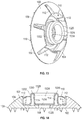
- FIG. 1 is a top perspective view of a protector washer for a snap button according to embodiments of the disclosure.
- FIG. 2 is a sectional view of the protector washer of FIG. 1 .
- FIG. 3 is a top perspective view of a protector washer for a snap button according to embodiments of the disclosure.
- FIG. 4 is a perspective view of a portion of the protector washer of FIG. 3 .
- FIG. 5 is a bottom perspective view of the protector washer of FIG. 3 .
- FIG. 6 is a bottom view of the protector washer of FIG. 3 .
- FIG. 7 is a perspective view of a protector washer for a snap button according to embodiments of the disclosure.
- FIG. 8 is a sectional view of the protector washer of FIG. 7 .
- FIG. 9 is a perspective view of a portion of the protector washer of FIG. 7 .
- FIG. 10 is a top perspective view of a protector washer for a snap button according to embodiments of the disclosure.
- FIG. 11 is a sectional view of the protector washer of FIG. 10 .
- FIG. 12 is a bottom perspective view of the protector washer of FIG. 10 .
- FIG. 13 is a perspective view of the protector washer of FIG. 1 assembled with a stud assembly of a snap button according to embodiments of the disclosure.
- FIG. 14 is a sectional view of the assembled protector washer and stud assembly of FIG. 13 .
- FIG. 15 illustrates the assembled protector washer and stud assembly of FIG. 13 secured to a trim cover with a rivet according to embodiments of the disclosure.
- FIG. 16 illustrates the assembled protector washer and stud assembly of FIG. 13 secured to a trim cover with a post according to embodiments of the disclosure.
- FIG. 17 illustrates the assembled protector washer and stud assembly of FIG. 13 secured to a trim cover with a screw according to embodiments of the disclosure.
- FIG. 18 is a perspective view of the protector washer of FIG. 7 assembled with a socket assembly of a snap button according to embodiments of the disclosure.
- FIG. 19 is a sectional view of the assembled protector washer and socket assembly of FIG. 18 .
- the protector washer can be assembled with a socket assembly and/or a stud assembly of a snap button.
- the protector washer assembled with the socket assembly and/or the stud assembly may allow for debris or other material to be removed from the snap button without affecting the engagement or snap function of the snap button.
- the protector washer assembled with the socket assembly and/or the stud assembly may also protect the socket assembly and/or the stud assembly when the snap button is installed on various or components or items including, but not limited to, trim covers.
- FIGS. 1 and 2 illustrate an example of a protector washer 100 according to various embodiments.
- the protector washer 100 may be assembled with a socket assembly or a stud assembly of a snap button (both of which are generally referred to herein as a “snap button component”, with it being understood that a socket assembly is a complimentary snap button component to the stud assembly and vice versa).
- the protector washer 100 may be constructed from various suitable materials or combinations of materials as desired, including, but not limited to, various metals, plastics, or composites.
- the protector washer 100 may be a hard plastic (including but not limited to polyoxymethylene or POM).
- the protector washer 100 formed from a hard plastic may be hard enough to not deform during assembly while enabling assembly of the snap button such that the protector washer 100 stays attached with the snap button.
- the material used to form the protector washer 100 does not need a high dimensional tolerance.
- the protector washer 100 may be formed from such materials into the protector washer 100 by various suitable forming methods as desired. In one non-limiting example, the protector washer 100 may be formed by molding polyoxymethylene.
- the protector washer 100 includes a base 102 and a side wall 104 extending from the base 102 .
- the base 102 has a perimeter edge 106 that forms a generally circular shape.
- the shape of the base 102 should not be considered limiting, as in other examples, the perimeter edge 106 of the base 102 may have other shapes as desired, including, but not limited to, triangular shapes, elliptical shapes, rectangular shapes, etc.
- the base 102 defines a securing aperture 108 that selectively receives a securing device or mechanism that secures the protector washer 100 and snap button component to a component or item such as the trim cover.
- the securing aperture 108 is centered on the base 102 , although it need not be in other examples.
- the side wall 104 of the protector washer 100 defines a receiving area 110 that may at least partially receive the snap button component when the protector washer 100 is assembled with the snap button component.
- the side wall 104 may have a tapered shape that decreases in height in a radial direction.
- a portion of the side wall 104 closer to the perimeter edge 106 of the base 102 may have a height that is less than a height of a portion of the side wall 104 that is closer to the center of the base 102 .
- the shape of the side wall 104 should not be considered limiting on the disclosure, and moreover the side wall 104 need not be tapered in other examples.
- the side wall 104 may have a stepped profile, squared profile, curved profile, or other profile as desired.
- the side wall 104 of the protector washer 100 may define one or more slits 112 that extends through a thickness of the side wall 104 . As illustrated in FIGS. 1 and 2 , the one or more slits 112 extend to (i.e., are in fluid communication with) the receiving area 110 of the protector washer 100 such that debris can be removed from the receiving area 110 through the one or more slits 112 . In various examples, such as the embodiment illustrated in FIGS. 1 and 2 , the side wall 104 defines a plurality of slits 112 , while in other embodiments, a single slit 112 may be utilized. The shape, size, number, or pattern of slits 112 should not be considered limiting on the disclosure.
- a height of one or more slits 112 may be less than the height of the side wall 104 or substantially the same as the height of the side wall 104 .
- the slits 112 may be provided at regular or irregular intervals along the side wall 104 .
- the slits 112 in FIGS. 1 and 2 are illustrated with squared or planar surfaces, in other examples, the slits 112 may have arcuate surfaces, angled surfaces, a saw-tooth profile, other arcuate surfaces, etc. as desired.
- the shape or size of one slit 112 may be the same as or different from the shape or size of another slit 112 .
- the protector washer 100 may also include one or more snap segments 114 .
- the one or more snap segments 114 may be included to facilitate engagement between the protector washer 100 and the snap button component assembled with the protector washer 100 .
- the snap segments 114 may be included when the protector washer 100 is for assembly with a stud assembly of the snap button and/or may be omitted when the protector washer 100 is for assembly with a socket assembly of the snap button.
- the snap segments 114 may be omitted when the protector washer 100 is for assembly with the stud assembly and/or may be included when the protector washer 100 is for assembly with the socket assembly.
- the one or more snap segments 114 are engageable with a stud assembly of the snap button.
- the one or more snap segments 114 when the one or more snap segments 114 are included, they may be provided on portions of the base 102 between the side wall 104 and the securing aperture 108 .
- the location of the one or more snap segments 114 should not be considered limiting on the disclosure (see FIGS. 7-9 ).
- a plurality of snap segments 114 each having a generally squared profile, are illustrated in the embodiment of FIGS. 1 and 2 , the number, shape, and size of the snap segments 114 should not be considered limiting on the disclosure.
- the shape, size, location, and number of snap segments 114 may be controlled depending on a desired stud assembly to be assembled with the protector washer 100 .
- the one or more snap segments 114 may include a rib portion 116 that facilitates engagement between the protector washer 100 and the snap button component.
- the profile and location of the rib portion 116 on the snap segments 114 should not be considered limiting on the disclosure.
- the rib portion 116 may be omitted and other suitable engagement features may be provided on the one or more snap segments 114 to facilitate engagement between the protector washer 100 and the snap button component.
- the protector washer 100 may optionally include one or more legs 118 on the base 102 opposite from the side wall 104 . In other cases, the legs 118 may be omitted. When included, the one or more legs 118 may facilitate attachment and/or positioning of the protector washer 100 at a particular location on a trim cover or other item as desired. In some cases, and as illustrated in FIGS. 1 and 2 , a plurality of legs 118 having a pointed profile. However, the number, shape, size, and location of the one or more legs 118 should not be considered limiting on the disclosure.
- FIGS. 3-6 illustrate an example of a protector washer 300 according to various embodiments.
- the protector washer 300 is substantially similar to the protector washer 100 except the protector washer 300 additionally includes one or more snap apertures 320 that are defined in the base 102 .
- the one or more snap apertures 320 may assist with the attachment of the protector washer to the snap button component such as the stud assembly.
- the one or more snap apertures 320 may also simplify the mold for the protector washer 300 and thereby simply the molding process for forming the protector washer 300 .
- the snap apertures 320 may also provide additional locations at which debris within the receiving area 110 can be removed from the receiving area 110 .
- the number of snap apertures 320 corresponds with the number of snap segments 114 and each snap aperture 320 is provided proximate to a corresponding snap segment 114 .
- the protector washer 300 includes a plurality of snap apertures 320 , each of which is provided proximate to a corresponding snap segment 114 .
- the shape, size, number, and location of the snap apertures 320 should not be considered limiting on the disclosure, and the snap apertures 320 need not correspond with particular snap segments 114 .
- the shape, size, location, and number of snap apertures 320 may be controlled depending on a desired stud assembly to be assembled with the protector washer 300 . Similar to the protector washer 100 , in various examples, the protector washer 300 is configured to engage with a stud assembly of a snap button.
- FIGS. 7-9 illustrate another example of a protector washer 700 according to various embodiments.
- the protector washer 700 is substantially similar to the protector washer 100 except that one or more snap segments 714 of the protector washer 700 are provided on the side wall 104 rather than between the side wall 104 and the securing aperture 108 as in the protector washer 100 .
- the one or more snap segments 714 may be provided proximate to or at a tallest portion of the side wall 104 , although they need not be in other examples.
- the snap segments 714 may be centered on the side wall 104 between a pair of adjacent slits 112 , although they need not be in other examples.
- each of the one or more snap segments 714 may include a rib portion 716 to facilitate engagement between the protector washer 700 and the snap button component.
- the number, shape, size, pattern, and location of the snap segments 714 should not be considered limiting on the disclosure.
- FIGS. 10-12 illustrate another example of a protector washer 1000 according to various embodiments.
- the protector washer 1000 is substantially similar to the protector washer 300 and includes the snap apertures 320 .
- the protector washer 1000 defines one or more pockets 1022 with openings provided on the side of the base 102 opposite from the side walls 104 .
- the number, shape, size, or location of the pockets 1022 should not be considered limiting on the disclosure.
- the side wall 104 may at least partially define one or more of the pockets 1022 .
- the one or more pockets 1022 may minimize or reduce shrinkage of portions of the protector washer 1000 during a forming process that may otherwise occur when the protector washer 1000 has portions with different thicknesses.
- the one or more pockets 1022 may also reduce the amount of material needed to form the protector washer 1000 , thereby reducing costs associated with producing the protector washer 1000 .
- the one or more pockets 1022 may also impart greater flexibility on the protector washer 1000 when the protector washer 1000 is assembled with the snap button component and/or when the protector washer 1000 is provided on an item such as the trim cover.
- the protector washer 100 , the protector washer 300 , and the protector washer 1000 may each be engageable with the stud assembly of the snap button, and the protector washer 700 may be engageable with the socket assembly of the snap button.
- FIGS. 13 and 14 illustrate the protector washer 100 assembled with a stud assembly 1324 of a snap button that is configured to engage a corresponding socket assembly (not shown).
- the stud assembly 1324 may be constructed from various materials which can be assembled with the protector washer 100 .
- the stud assembly 1324 may be constructed from a metal, which may include, but is not limited to, stainless steel, steel, brass, zinc, and/or aluminum. Various other materials may be utilized for the stud assembly 1324 as desired.
- the stud assembly 1324 includes a base 1326 and a protrusion 1328 extending from the base 1326 and that includes an engagement portion 1332 .
- an engagement portion 1332 of the protrusion 1328 may have a diameter that is greater than a diameter of a portion of the protrusion proximate to the base 1326 to facilitate engagement with a corresponding socket assembly.
- the protrusion 1328 defines a receiving area 1330 . It will be appreciated that the particular stud assembly 1324 is provided for reference purposes only and should not be considered limiting on the disclosure and is provided for reference purposes only, and the protector washers described herein may be assembled with any stud assembly of a snap button as desired.
- the snap segments 114 may be at least partially positioned within the receiving area 1330 of the protrusion 1328 .
- the rib portion of the snap segments 114 may engage the engagement portion 1332 of the protrusion 1328 within the receiving area 1330 to facilitate engagement between the protector washer 100 and the stud assembly 1324 and to position the stud assembly 1324 within the receiving area 110 of the protector washer 100 .
- the base 1326 of the stud assembly 1324 may define a securing aperture 1334 .
- the securing aperture 1334 of the stud assembly 1324 may be substantially aligned with the securing aperture 108 of the protector washer 100 .
- various securing devices or mechanisms may be at least partially inserted through the aligned securing apertures 108 , 1334 to secured the assembled protector washer 100 and stud assembly 1324 on a trim cover 1552 (or other component or item as desired).
- the securing device is a rivet 1536
- the securing device is a post 1638
- the securing device is a screw 1740 .
- Various other suitable securing devices may be utilized as desired.
- the securing device is installed in a pre-punched aperture in the trim cover 1552 .
- the protector washer 100 may cover the pre-punched aperture to improve the appearance and to provide protection to the portion of the trim cover 1552 surrounding the pre-punched aperture.
- the protector washer 100 also adds protection to the stud assembly 1324 to minimize or prevent potential damage.
- the legs 118 of the protector washer 100 may at least partially penetrate (or otherwise engage) the trim cover 1552 to further secure and/or position the assembled protector washer 100 and stud assembly 1324 relative to the trim cover 1552 .
- FIGS. 18 and 19 illustrate the protector washer 700 assembled with a socket assembly 1842 of a snap button that is configured to engage a corresponding stud assembly (not shown).
- the socket assembly 1842 may be constructed from various materials which can be assembled with the protector washer 100 .
- the socket assembly 1842 may be constructed from a metal, which may include, but is not limited to, stainless steel, steel, brass, zinc, and/or aluminum. Various other materials may be utilized for the socket assembly 1842 as desired.
- the socket assembly 1842 includes a cage 1844 that defines a receiving area 1846 , and an engagement member such as an annular spring 1850 is incorporated into the receiving area 1846 .
- an engagement member such as an annular spring 1850 is incorporated into the receiving area 1846 .
- the snap segments 714 may at least partially engage the cage 1844 to facilitate engagement and positioning of the socket assembly 1842 within the receiving area 110 of the protector washer 700 .
- the cage 1844 of the socket assembly 1842 may define a securing aperture 1848 .
- the securing aperture 1848 of the socket assembly 1842 may be substantially aligned with the securing aperture 108 of the protector washer 700 .
- Securing devices including but not limited to the rivet 1536 , the post 1638 , and/or the screw 1740 may be at least partially inserted through the aligned apertures 108 , 1848 to secure and position the assembled protector washer 700 and socket assembly 1842 relative to an item such as the trim cover 1552 (or other component or item as desired).
- Illustration 1 A protector washer comprising: a base defining a center aperture; a side wall defining at least one slit; and a snap segment configured to engage a snap button.
- Illustration 2 The protector washer of any preceding or subsequent illustrations or combination of illustrations, wherein the snap segment is on the side wall.
- Illustration 3 The protector washer of any preceding or subsequent illustrations or combination of illustrations, wherein the snap segment is on the base between the center aperture and the side wall.
- Illustration 4 A snap button assembly comprising: a snap button; and a protector washer comprising: a base; a side wall defining a receiving area and at least one slit, wherein the snap button is at least partially positioned within the receiving area.
- a protector washer comprising: a base defining a securing aperture; a side wall extending from the base and defining at least one slit extending through a thickness of the side wall; and a snap segment configured to engage a snap button component.
- Illustration 6 The protector washer of any preceding or subsequent illustrations or combination of illustrations, wherein the snap segment is on the side wall.
- Illustration 7 The protector washer of any preceding or subsequent illustrations or combination of illustrations, wherein the base comprises a perimeter edge, wherein a height of a portion of the side wall proximate to the perimeter edge is less than a height of a radially inward portion of the side wall that is radially inward from the perimeter edge, and wherein the snap segment is on the radially inward portion of the side wall.
- Illustration 8 The protector washer of any preceding or subsequent illustrations or combination of illustrations, wherein the side wall further defines a receiving area, and wherein the at least one slit is in fluid communication with the receiving area.
- Illustration 9 The protector washer of any preceding or subsequent illustrations or combination of illustrations, wherein the snap segment is on the base and between the side wall and the securing aperture.
- Illustration 10 The protector washer of any preceding or subsequent illustrations or combination of illustrations, wherein the base defines at least one pocket on a side of the base opposite from the side wall.
- Illustration 11 The protector washer of any preceding or subsequent illustrations or combination of illustrations, further comprising at least one leg on a side of the base opposite from the side wall.
- Illustration 12 The protector washer of any preceding or subsequent illustrations or combination of illustrations, wherein the base comprises a perimeter edge, and wherein a height of a portion of the side wall proximate to the perimeter edge is less than a height of a radially inward portion of the side wall that is radially inward from the perimeter edge.
- Illustration 13 The protector washer of any preceding or subsequent illustrations or combination of illustrations, wherein the snap segment is a first snap segment of a plurality of snap segments and wherein the slit is a first slit of a plurality of slits.
- Illustration 14 The protector washer of any preceding or subsequent illustrations or combination of illustrations, wherein the snap segment comprises a rib portion.
- Illustration 15 The protector washer of any preceding or subsequent illustrations or combination of illustrations, wherein the base further defines at least one snap aperture, and wherein the at least one snap aperture is proximate to the snap segment.
- a snap button assembly comprising: a snap button component; and a protector washer comprising: a base; and a side wall defining a receiving area and at least one slit extending through a thickness of the side wall, wherein the snap button component is at least partially positioned within the receiving area.
- Illustration 17 The snap button assembly of any preceding or subsequent illustrations or combination of illustrations, wherein the snap button component comprises a socket assembly, wherein the protector washer further comprises a snap segment on the side wall, and wherein the snap segment is engaged with the socket assembly at least partially positioned within the receiving area.
- Illustration 18 The snap button assembly of any preceding or subsequent illustrations or combination of illustrations, wherein the snap button component comprises a stud assembly, wherein the protector washer further comprises a snap segment within the receiving area and on the base, on the side wall, and wherein the snap segment is engaged with the stud assembly at least partially positioned within the receiving area.
- Illustration 19 The snap button assembly of any preceding or subsequent illustrations or combination of illustrations, wherein the base comprises a perimeter edge, and wherein a height of a portion of the side wall proximate to the perimeter edge is less than a height of a radially inward portion of the side wall that is radially inward from the perimeter edge.
- Illustration 20 The snap button assembly of any preceding or subsequent illustrations or combination of illustrations, wherein the protector washer further comprises a snap segment configured to engage the snap button component, and wherein the snap segment is on at least one of the side wall or the base within the receiving area.
- a protector washer comprising: a base; a side wall extending from the base and defining: a receiving area; and at least one slit extending through a thickness of the side wall and in fluid communication with the receiving area; and a snap segment configured to engage a snap button component.
- Illustration 22 The protector washer of any preceding or subsequent illustrations or combination of illustrations, wherein the snap segment is on the side wall.
- Illustration 23 The protector washer of any preceding or subsequent illustrations or combination of illustrations, wherein the snap segment is on the base and within the receiving area.
- Illustration 24 The protector washer of any preceding or subsequent illustrations or combination of illustrations, wherein the base further comprises a securing aperture, and wherein the snap segment is within the receiving area between the securing aperture and the side wall.
- Illustration 25 The protector washer of any preceding or subsequent illustrations or combination of illustrations, wherein the base defines at least one pocket on a side of the base opposite from the side wall.
Landscapes
- Snaps, Bayonet Connections, Set Pins, And Snap Rings (AREA)
Abstract
Description
Claims (19)
Priority Applications (1)
| Application Number | Priority Date | Filing Date | Title |
|---|---|---|---|
| US16/843,724 US11219284B2 (en) | 2019-05-17 | 2020-04-08 | Snap button assembly |
Applications Claiming Priority (2)
| Application Number | Priority Date | Filing Date | Title |
|---|---|---|---|
| US201962849436P | 2019-05-17 | 2019-05-17 | |
| US16/843,724 US11219284B2 (en) | 2019-05-17 | 2020-04-08 | Snap button assembly |
Publications (2)
| Publication Number | Publication Date |
|---|---|
| US20200359751A1 US20200359751A1 (en) | 2020-11-19 |
| US11219284B2 true US11219284B2 (en) | 2022-01-11 |
Family
ID=73245244
Family Applications (1)
| Application Number | Title | Priority Date | Filing Date |
|---|---|---|---|
| US16/843,724 Active US11219284B2 (en) | 2019-05-17 | 2020-04-08 | Snap button assembly |
Country Status (1)
| Country | Link |
|---|---|
| US (1) | US11219284B2 (en) |
Citations (21)
| Publication number | Priority date | Publication date | Assignee | Title |
|---|---|---|---|---|
| US557704A (en) * | 1896-04-07 | William s | ||
| US1904122A (en) * | 1932-08-20 | 1933-04-18 | Scovill Manufacturing Co | Detachable snap fastener for articles to be laundered |
| US2745159A (en) * | 1951-03-30 | 1956-05-15 | United Carr Fastener Corp | Heat sealable plastic fastener and assembly |
| US2817134A (en) * | 1953-08-17 | 1957-12-24 | Scovill Manufacturing Co | Snap fastener |
| US4757662A (en) * | 1987-02-09 | 1988-07-19 | G.B.R. Enterprises | Membrane roofing fastener |
| US5647107A (en) * | 1994-07-14 | 1997-07-15 | Permar Systems, Inc. | Snap Grommet |
| US20010004784A1 (en) * | 1999-12-02 | 2001-06-28 | Rocco Calabrese | Fast-fit device for fastening a mat to a carpet fixed to the floor of a vehicle |
| US20020078537A1 (en) * | 2000-12-27 | 2002-06-27 | Tomio Shibuya | Mat fastener |
| US20090151135A1 (en) * | 2007-12-12 | 2009-06-18 | Hyundai Motor Company | Mat for vehicles |
| USD626451S1 (en) * | 2009-09-18 | 2010-11-02 | Ykk Corporation Of America | Fastener component |
| US20110113600A1 (en) * | 2008-02-29 | 2011-05-19 | Ykk Corporation | Male Snap Part and Female Snap Part |
| US20120124791A1 (en) * | 2009-06-10 | 2012-05-24 | Ykk Corporation | Snap Button |
| US8561269B2 (en) | 2010-09-17 | 2013-10-22 | Ykk Corporation | Fastener having a flexible base |
| USD695591S1 (en) * | 2011-05-23 | 2013-12-17 | S.C. Johnson & Son, Inc. | Fastener |
| USD700501S1 (en) * | 2011-05-23 | 2014-03-04 | S.C. Johnson & Son, Inc. | Fastener |
| US8702478B2 (en) * | 2009-05-08 | 2014-04-22 | Michael Loveless | Angle grinder dust shroud with unitary adjustable mounting collar |
| US9845036B2 (en) | 2015-07-29 | 2017-12-19 | Macneil Ip Llc | Multi-vehicle retention grommet |
| US10124742B2 (en) * | 2017-03-13 | 2018-11-13 | Honda Patents & Technologies North America, Llc. | Fastener apparatus, and methods of use and manufacture thereof |
| US10130148B1 (en) * | 2017-11-30 | 2018-11-20 | Duraflex Hong Kong Limited | Snap button |
| USD899967S1 (en) * | 2019-04-23 | 2020-10-27 | Duraflex Hong Kong Limited | Snap button |
| US10864836B2 (en) * | 2018-10-24 | 2020-12-15 | Fca Us Llc | Vehicle having grommet apparatus |
-
2020
- 2020-04-08 US US16/843,724 patent/US11219284B2/en active Active
Patent Citations (23)
| Publication number | Priority date | Publication date | Assignee | Title |
|---|---|---|---|---|
| US557704A (en) * | 1896-04-07 | William s | ||
| US1904122A (en) * | 1932-08-20 | 1933-04-18 | Scovill Manufacturing Co | Detachable snap fastener for articles to be laundered |
| US2745159A (en) * | 1951-03-30 | 1956-05-15 | United Carr Fastener Corp | Heat sealable plastic fastener and assembly |
| US2817134A (en) * | 1953-08-17 | 1957-12-24 | Scovill Manufacturing Co | Snap fastener |
| US4757662A (en) * | 1987-02-09 | 1988-07-19 | G.B.R. Enterprises | Membrane roofing fastener |
| US5647107A (en) * | 1994-07-14 | 1997-07-15 | Permar Systems, Inc. | Snap Grommet |
| US20010004784A1 (en) * | 1999-12-02 | 2001-06-28 | Rocco Calabrese | Fast-fit device for fastening a mat to a carpet fixed to the floor of a vehicle |
| US20020078537A1 (en) * | 2000-12-27 | 2002-06-27 | Tomio Shibuya | Mat fastener |
| US20090151135A1 (en) * | 2007-12-12 | 2009-06-18 | Hyundai Motor Company | Mat for vehicles |
| US20130152347A1 (en) * | 2008-02-29 | 2013-06-20 | Ykk Corporation | Male Snap Part |
| US20110113600A1 (en) * | 2008-02-29 | 2011-05-19 | Ykk Corporation | Male Snap Part and Female Snap Part |
| US8702478B2 (en) * | 2009-05-08 | 2014-04-22 | Michael Loveless | Angle grinder dust shroud with unitary adjustable mounting collar |
| US20120124791A1 (en) * | 2009-06-10 | 2012-05-24 | Ykk Corporation | Snap Button |
| USD626452S1 (en) | 2009-09-18 | 2010-11-02 | Ykk Corporation Of America | Fastener component |
| USD626451S1 (en) * | 2009-09-18 | 2010-11-02 | Ykk Corporation Of America | Fastener component |
| US8561269B2 (en) | 2010-09-17 | 2013-10-22 | Ykk Corporation | Fastener having a flexible base |
| USD695591S1 (en) * | 2011-05-23 | 2013-12-17 | S.C. Johnson & Son, Inc. | Fastener |
| USD700501S1 (en) * | 2011-05-23 | 2014-03-04 | S.C. Johnson & Son, Inc. | Fastener |
| US9845036B2 (en) | 2015-07-29 | 2017-12-19 | Macneil Ip Llc | Multi-vehicle retention grommet |
| US10124742B2 (en) * | 2017-03-13 | 2018-11-13 | Honda Patents & Technologies North America, Llc. | Fastener apparatus, and methods of use and manufacture thereof |
| US10130148B1 (en) * | 2017-11-30 | 2018-11-20 | Duraflex Hong Kong Limited | Snap button |
| US10864836B2 (en) * | 2018-10-24 | 2020-12-15 | Fca Us Llc | Vehicle having grommet apparatus |
| USD899967S1 (en) * | 2019-04-23 | 2020-10-27 | Duraflex Hong Kong Limited | Snap button |
Also Published As
| Publication number | Publication date |
|---|---|
| US20200359751A1 (en) | 2020-11-19 |
Similar Documents
| Publication | Publication Date | Title |
|---|---|---|
| US11746952B2 (en) | Back plate assemblies for home hardware | |
| USD839078S1 (en) | Slide clip | |
| US3210820A (en) | One-way snap fastener combination | |
| US9610904B2 (en) | Push pin with over-travel stop | |
| EP2639118B1 (en) | Through anchor | |
| US9067547B2 (en) | Door belt molding for vehicle | |
| US9770074B2 (en) | Cap structure having a plurality of breach hole features and zipper head assembly structure using the same | |
| US7272862B1 (en) | Pant cuff protecting device and method | |
| US9463727B2 (en) | Vehicle seat covering assembly | |
| US20050012321A1 (en) | Deflection fitting for a safety belt | |
| US20190159556A1 (en) | Cap structure and zipper head assembly structure | |
| US8777468B2 (en) | Fog lamp cover mounting structure | |
| CN105221531A (en) | The average alignment system of elasticity and method | |
| US11219284B2 (en) | Snap button assembly | |
| USD970851S1 (en) | Pants with integrated removable waistpack | |
| US20030209959A1 (en) | Runner for a drawer | |
| US11122868B2 (en) | Method of manufacturing a cap structure | |
| ES2312933T3 (en) | WHEEL COVER FOR MOTOR VEHICLE. | |
| US10946781B2 (en) | Vehicle floor mat retainer | |
| US4867398A (en) | Radio mounting assembly having self-aligning trim bezel | |
| CN109890239B (en) | Convex part of snap fastener and snap fastener | |
| JP2003034102A (en) | Wheel cap structure | |
| US3604052A (en) | Self-captivating handle | |
| US4719674A (en) | Snap-type fastener | |
| US20140053373A1 (en) | Buttons |
Legal Events
| Date | Code | Title | Description |
|---|---|---|---|
| AS | Assignment |
Owner name: YKK CORPORATION OF AMERICA, GEORGIA Free format text: ASSIGNMENT OF ASSIGNORS INTEREST;ASSIGNORS:LECOMPTE, CHUCK G.;SHARP, JONATHAN H.;WILSON, WILLIAM GEORGE;SIGNING DATES FROM 20200401 TO 20200406;REEL/FRAME:052349/0353 |
|
| FEPP | Fee payment procedure |
Free format text: ENTITY STATUS SET TO UNDISCOUNTED (ORIGINAL EVENT CODE: BIG.); ENTITY STATUS OF PATENT OWNER: LARGE ENTITY |
|
| STPP | Information on status: patent application and granting procedure in general |
Free format text: NON FINAL ACTION MAILED |
|
| STPP | Information on status: patent application and granting procedure in general |
Free format text: RESPONSE TO NON-FINAL OFFICE ACTION ENTERED AND FORWARDED TO EXAMINER |
|
| STPP | Information on status: patent application and granting procedure in general |
Free format text: FINAL REJECTION MAILED |
|
| STPP | Information on status: patent application and granting procedure in general |
Free format text: RESPONSE AFTER FINAL ACTION FORWARDED TO EXAMINER |
|
| STPP | Information on status: patent application and granting procedure in general |
Free format text: NOTICE OF ALLOWANCE MAILED -- APPLICATION RECEIVED IN OFFICE OF PUBLICATIONS |
|
| STPP | Information on status: patent application and granting procedure in general |
Free format text: PUBLICATIONS -- ISSUE FEE PAYMENT VERIFIED |
|
| STCF | Information on status: patent grant |
Free format text: PATENTED CASE |
|
| MAFP | Maintenance fee payment |
Free format text: PAYMENT OF MAINTENANCE FEE, 4TH YEAR, LARGE ENTITY (ORIGINAL EVENT CODE: M1551); ENTITY STATUS OF PATENT OWNER: LARGE ENTITY Year of fee payment: 4 |