US11219269B2 - Co-injection moulded sports boot - Google Patents
Co-injection moulded sports boot Download PDFInfo
- Publication number
- US11219269B2 US11219269B2 US15/178,662 US201615178662A US11219269B2 US 11219269 B2 US11219269 B2 US 11219269B2 US 201615178662 A US201615178662 A US 201615178662A US 11219269 B2 US11219269 B2 US 11219269B2
- Authority
- US
- United States
- Prior art keywords
- wall
- injection
- zone
- plastics
- sports boot
- Prior art date
- Legal status (The legal status is an assumption and is not a legal conclusion. Google has not performed a legal analysis and makes no representation as to the accuracy of the status listed.)
- Active, expires
Links
Images


Classifications
-
- A—HUMAN NECESSITIES
- A43—FOOTWEAR
- A43B—CHARACTERISTIC FEATURES OF FOOTWEAR; PARTS OF FOOTWEAR
- A43B5/00—Footwear for sporting purposes
- A43B5/04—Ski or like boots
- A43B5/0427—Ski or like boots characterised by type or construction details
- A43B5/0482—Ski or like boots characterised by type or construction details made from materials with different rigidities
-
- A—HUMAN NECESSITIES
- A43—FOOTWEAR
- A43B—CHARACTERISTIC FEATURES OF FOOTWEAR; PARTS OF FOOTWEAR
- A43B1/00—Footwear characterised by the material
- A43B1/0072—Footwear characterised by the material made at least partially of transparent or translucent materials
-
- A—HUMAN NECESSITIES
- A43—FOOTWEAR
- A43B—CHARACTERISTIC FEATURES OF FOOTWEAR; PARTS OF FOOTWEAR
- A43B5/00—Footwear for sporting purposes
- A43B5/04—Ski or like boots
- A43B5/0411—Ski or like boots for cross-country
-
- A—HUMAN NECESSITIES
- A43—FOOTWEAR
- A43B—CHARACTERISTIC FEATURES OF FOOTWEAR; PARTS OF FOOTWEAR
- A43B5/00—Footwear for sporting purposes
- A43B5/04—Ski or like boots
- A43B5/0486—Ski or like boots characterized by the material
-
- A—HUMAN NECESSITIES
- A43—FOOTWEAR
- A43B—CHARACTERISTIC FEATURES OF FOOTWEAR; PARTS OF FOOTWEAR
- A43B5/00—Footwear for sporting purposes
- A43B5/04—Ski or like boots
- A43B5/0496—Ski or like boots boots for touring or hiking skis
-
- B—PERFORMING OPERATIONS; TRANSPORTING
- B29—WORKING OF PLASTICS; WORKING OF SUBSTANCES IN A PLASTIC STATE IN GENERAL
- B29C—SHAPING OR JOINING OF PLASTICS; SHAPING OF MATERIAL IN A PLASTIC STATE, NOT OTHERWISE PROVIDED FOR; AFTER-TREATMENT OF THE SHAPED PRODUCTS, e.g. REPAIRING
- B29C45/00—Injection moulding, i.e. forcing the required volume of moulding material through a nozzle into a closed mould; Apparatus therefor
- B29C45/16—Making multilayered or multicoloured articles
- B29C45/1642—Making multilayered or multicoloured articles having a "sandwich" structure
-
- B—PERFORMING OPERATIONS; TRANSPORTING
- B29—WORKING OF PLASTICS; WORKING OF SUBSTANCES IN A PLASTIC STATE IN GENERAL
- B29C—SHAPING OR JOINING OF PLASTICS; SHAPING OF MATERIAL IN A PLASTIC STATE, NOT OTHERWISE PROVIDED FOR; AFTER-TREATMENT OF THE SHAPED PRODUCTS, e.g. REPAIRING
- B29C45/00—Injection moulding, i.e. forcing the required volume of moulding material through a nozzle into a closed mould; Apparatus therefor
- B29C45/16—Making multilayered or multicoloured articles
- B29C45/1676—Making multilayered or multicoloured articles using a soft material and a rigid material, e.g. making articles with a sealing part
-
- B—PERFORMING OPERATIONS; TRANSPORTING
- B29—WORKING OF PLASTICS; WORKING OF SUBSTANCES IN A PLASTIC STATE IN GENERAL
- B29C—SHAPING OR JOINING OF PLASTICS; SHAPING OF MATERIAL IN A PLASTIC STATE, NOT OTHERWISE PROVIDED FOR; AFTER-TREATMENT OF THE SHAPED PRODUCTS, e.g. REPAIRING
- B29C45/00—Injection moulding, i.e. forcing the required volume of moulding material through a nozzle into a closed mould; Apparatus therefor
- B29C45/17—Component parts, details or accessories; Auxiliary operations
- B29C45/20—Injection nozzles
- B29C45/22—Multiple nozzle systems
-
- B—PERFORMING OPERATIONS; TRANSPORTING
- B29—WORKING OF PLASTICS; WORKING OF SUBSTANCES IN A PLASTIC STATE IN GENERAL
- B29D—PRODUCING PARTICULAR ARTICLES FROM PLASTICS OR FROM SUBSTANCES IN A PLASTIC STATE
- B29D35/00—Producing footwear
- B29D35/0009—Producing footwear by injection moulding; Apparatus therefor
- B29D35/0018—Moulds
-
- B—PERFORMING OPERATIONS; TRANSPORTING
- B29—WORKING OF PLASTICS; WORKING OF SUBSTANCES IN A PLASTIC STATE IN GENERAL
- B29D—PRODUCING PARTICULAR ARTICLES FROM PLASTICS OR FROM SUBSTANCES IN A PLASTIC STATE
- B29D35/00—Producing footwear
- B29D35/02—Producing footwear made in one piece using a moulding technique, e.g. by injection moulding or casting
- B29D35/04—Producing footwear made in one piece using a moulding technique, e.g. by injection moulding or casting having multilayered parts
-
- B—PERFORMING OPERATIONS; TRANSPORTING
- B29—WORKING OF PLASTICS; WORKING OF SUBSTANCES IN A PLASTIC STATE IN GENERAL
- B29D—PRODUCING PARTICULAR ARTICLES FROM PLASTICS OR FROM SUBSTANCES IN A PLASTIC STATE
- B29D35/00—Producing footwear
- B29D35/12—Producing parts thereof, e.g. soles, heels, uppers, by a moulding technique
- B29D35/14—Multilayered parts
- B29D35/142—Soles
-
- B—PERFORMING OPERATIONS; TRANSPORTING
- B29—WORKING OF PLASTICS; WORKING OF SUBSTANCES IN A PLASTIC STATE IN GENERAL
- B29D—PRODUCING PARTICULAR ARTICLES FROM PLASTICS OR FROM SUBSTANCES IN A PLASTIC STATE
- B29D35/00—Producing footwear
- B29D35/12—Producing parts thereof, e.g. soles, heels, uppers, by a moulding technique
- B29D35/14—Multilayered parts
- B29D35/146—Uppers
-
- B—PERFORMING OPERATIONS; TRANSPORTING
- B29—WORKING OF PLASTICS; WORKING OF SUBSTANCES IN A PLASTIC STATE IN GENERAL
- B29D—PRODUCING PARTICULAR ARTICLES FROM PLASTICS OR FROM SUBSTANCES IN A PLASTIC STATE
- B29D35/00—Producing footwear
- B29D35/12—Producing parts thereof, e.g. soles, heels, uppers, by a moulding technique
- B29D35/14—Multilayered parts
- B29D35/148—Moulds or apparatus therefor
-
- B—PERFORMING OPERATIONS; TRANSPORTING
- B29—WORKING OF PLASTICS; WORKING OF SUBSTANCES IN A PLASTIC STATE IN GENERAL
- B29C—SHAPING OR JOINING OF PLASTICS; SHAPING OF MATERIAL IN A PLASTIC STATE, NOT OTHERWISE PROVIDED FOR; AFTER-TREATMENT OF THE SHAPED PRODUCTS, e.g. REPAIRING
- B29C45/00—Injection moulding, i.e. forcing the required volume of moulding material through a nozzle into a closed mould; Apparatus therefor
- B29C45/16—Making multilayered or multicoloured articles
- B29C2045/167—Making multilayered or multicoloured articles injecting the second layer through the first layer
-
- B—PERFORMING OPERATIONS; TRANSPORTING
- B29—WORKING OF PLASTICS; WORKING OF SUBSTANCES IN A PLASTIC STATE IN GENERAL
- B29C—SHAPING OR JOINING OF PLASTICS; SHAPING OF MATERIAL IN A PLASTIC STATE, NOT OTHERWISE PROVIDED FOR; AFTER-TREATMENT OF THE SHAPED PRODUCTS, e.g. REPAIRING
- B29C45/00—Injection moulding, i.e. forcing the required volume of moulding material through a nozzle into a closed mould; Apparatus therefor
- B29C45/16—Making multilayered or multicoloured articles
- B29C2045/1692—Making multilayered or multicoloured articles one layer comprising fibres
-
- B—PERFORMING OPERATIONS; TRANSPORTING
- B29—WORKING OF PLASTICS; WORKING OF SUBSTANCES IN A PLASTIC STATE IN GENERAL
- B29C—SHAPING OR JOINING OF PLASTICS; SHAPING OF MATERIAL IN A PLASTIC STATE, NOT OTHERWISE PROVIDED FOR; AFTER-TREATMENT OF THE SHAPED PRODUCTS, e.g. REPAIRING
- B29C45/00—Injection moulding, i.e. forcing the required volume of moulding material through a nozzle into a closed mould; Apparatus therefor
- B29C45/17—Component parts, details or accessories; Auxiliary operations
- B29C45/26—Moulds
- B29C45/27—Sprue channels ; Runner channels or runner nozzles
- B29C45/2701—Details not specific to hot or cold runner channels
- B29C45/2708—Gates
-
- B—PERFORMING OPERATIONS; TRANSPORTING
- B29—WORKING OF PLASTICS; WORKING OF SUBSTANCES IN A PLASTIC STATE IN GENERAL
- B29K—INDEXING SCHEME ASSOCIATED WITH SUBCLASSES B29B, B29C OR B29D, RELATING TO MOULDING MATERIALS OR TO MATERIALS FOR MOULDS, REINFORCEMENTS, FILLERS OR PREFORMED PARTS, e.g. INSERTS
- B29K2105/00—Condition, form or state of moulded material or of the material to be shaped
- B29K2105/0058—Liquid or visquous
-
- B—PERFORMING OPERATIONS; TRANSPORTING
- B29—WORKING OF PLASTICS; WORKING OF SUBSTANCES IN A PLASTIC STATE IN GENERAL
- B29K—INDEXING SCHEME ASSOCIATED WITH SUBCLASSES B29B, B29C OR B29D, RELATING TO MOULDING MATERIALS OR TO MATERIALS FOR MOULDS, REINFORCEMENTS, FILLERS OR PREFORMED PARTS, e.g. INSERTS
- B29K2105/00—Condition, form or state of moulded material or of the material to be shaped
- B29K2105/06—Condition, form or state of moulded material or of the material to be shaped containing reinforcements, fillers or inserts
-
- B—PERFORMING OPERATIONS; TRANSPORTING
- B29—WORKING OF PLASTICS; WORKING OF SUBSTANCES IN A PLASTIC STATE IN GENERAL
- B29K—INDEXING SCHEME ASSOCIATED WITH SUBCLASSES B29B, B29C OR B29D, RELATING TO MOULDING MATERIALS OR TO MATERIALS FOR MOULDS, REINFORCEMENTS, FILLERS OR PREFORMED PARTS, e.g. INSERTS
- B29K2307/00—Use of elements other than metals as reinforcement
- B29K2307/04—Carbon
-
- B—PERFORMING OPERATIONS; TRANSPORTING
- B29—WORKING OF PLASTICS; WORKING OF SUBSTANCES IN A PLASTIC STATE IN GENERAL
- B29K—INDEXING SCHEME ASSOCIATED WITH SUBCLASSES B29B, B29C OR B29D, RELATING TO MOULDING MATERIALS OR TO MATERIALS FOR MOULDS, REINFORCEMENTS, FILLERS OR PREFORMED PARTS, e.g. INSERTS
- B29K2309/00—Use of inorganic materials not provided for in groups B29K2303/00 - B29K2307/00, as reinforcement
- B29K2309/08—Glass
-
- B—PERFORMING OPERATIONS; TRANSPORTING
- B29—WORKING OF PLASTICS; WORKING OF SUBSTANCES IN A PLASTIC STATE IN GENERAL
- B29K—INDEXING SCHEME ASSOCIATED WITH SUBCLASSES B29B, B29C OR B29D, RELATING TO MOULDING MATERIALS OR TO MATERIALS FOR MOULDS, REINFORCEMENTS, FILLERS OR PREFORMED PARTS, e.g. INSERTS
- B29K2995/00—Properties of moulding materials, reinforcements, fillers, preformed parts or moulds
- B29K2995/0018—Properties of moulding materials, reinforcements, fillers, preformed parts or moulds having particular optical properties, e.g. fluorescent or phosphorescent
- B29K2995/002—Coloured
- B29K2995/0021—Multi-coloured
-
- B—PERFORMING OPERATIONS; TRANSPORTING
- B29—WORKING OF PLASTICS; WORKING OF SUBSTANCES IN A PLASTIC STATE IN GENERAL
- B29K—INDEXING SCHEME ASSOCIATED WITH SUBCLASSES B29B, B29C OR B29D, RELATING TO MOULDING MATERIALS OR TO MATERIALS FOR MOULDS, REINFORCEMENTS, FILLERS OR PREFORMED PARTS, e.g. INSERTS
- B29K2995/00—Properties of moulding materials, reinforcements, fillers, preformed parts or moulds
- B29K2995/0037—Other properties
- B29K2995/007—Hardness
-
- B—PERFORMING OPERATIONS; TRANSPORTING
- B29—WORKING OF PLASTICS; WORKING OF SUBSTANCES IN A PLASTIC STATE IN GENERAL
- B29L—INDEXING SCHEME ASSOCIATED WITH SUBCLASS B29C, RELATING TO PARTICULAR ARTICLES
- B29L2031/00—Other particular articles
- B29L2031/48—Wearing apparel
- B29L2031/50—Footwear, e.g. shoes or parts thereof
- B29L2031/501—Boots
Definitions
- the invention relates to a sports boot element such as all or part of a shell, a lower shell or a cuff or a tongue, notably of an alpine skiing or cross-country skiing ski boot, and to a sports boot as such comprising such an element. It relates in particular to all or part of a ski boot. It also relates to a method for manufacturing such a sports boot element.
- a ski boot requires on the one hand, significant strength and rigidity and, on the other hand, a high level of comfort. Specifically, such a boot experiences numerous loadings when in use and has therefore to have good strength. A high degree of rigidity is also needed in order to achieve good boot performance as the boot, being the interface between the skier and the ski, transmits the loads from the skier to the ski in order to guide the latter.
- the constraints in terms of comfort are just as stringent.
- the boot has notably to be flexible enough that it allows the skier to open it in order to put it on and take it off, allow him to bend his knees forwards in order to ski, and provide him with sufficient comfort despite being used in extreme temperature conditions and in a wet and harsh environment.
- boot elements comprising one or more plastics materials.
- the boots comprise rigid plastic zones situated on the outside, these partially or fully covering a more flexible inner boot or comfort upper that provides the comfort.
- a first method for manufacturing a sports boot element or sports boot of the prior art is to manufacture the various plastic sub-elements separately by injection moulding and then assemble them mechanically.
- the disadvantage with such a method is that it requires a long manufacturing time and is expensive because it requires a specific mould for each sub-element, requires the various manufactured sub-elements to be stored separately, then requires a step of mechanically assembling these sub-elements.
- Another method for manufacturing sports boots in the prior art is to use the two-shot injection moulding technique which involves manufacturing a boot wall by injection of a first layer of a first plastics material and then injection overmoulding, directly onto this first layer still in place on the internal part of its mould, after it has cooled and hardened and after the external part of the mould has been changed, a second layer made of the same material or from a plastics material said to be “compatible” with that of the first layer, so that the two plastics materials naturally weld together at their superposed surfaces.
- a second layer made of the same material or from a plastics material said to be “compatible” with that of the first layer, so that the two plastics materials naturally weld together at their superposed surfaces.
- this method entails an additional specific external mould. Specifically, before the second material is injection overmoulded, it is necessary to change the external part of the mould, this entailing additional production cycle time and additional mould manufacture costs.
- Another disadvantage associated with this method lies in the cohesion of the material at the boundary between the two materials. Specifically, it is found that the bond between the two materials can be weak.
- a first subject of the present invention is a sports boot that is easy to put on and take off, in order to achieve acceptable levels of comfort while at the same time offering good rigidity spread across the appropriate zones in order to obtain a boot that performs well to suit its use.
- a second subject of the present invention involves offering a sports boot the method of manufacturing of which remains simple and inexpensive.
- a third object of the invention is to propose a sports boot of attractive aesthetic appearance.
- the wall of a sports boot element comprises:
- FIG. 1 depicts a side view of a ski boot according to one embodiment of the invention.
- FIG. 2 depicts a side view of a ski boot lower shell according to one embodiment of the invention.
- FIG. 3 depicts a side view of a ski boot lower shell according to a first embodiment of the invention.
- FIG. 4 depicts a front view in cross section on a vertical plane at the front part of the ski boot lower shell according to the first embodiment of the invention.
- FIG. 5 depicts a rear view in cross section on a vertical plane at the rear part of the ski boot lower shell according to the first embodiment of the invention.
- FIG. 6 depicts a plan view in section on a horizontal plane at the upper part of the ski boot lower shell according to the first embodiment of the invention.
- FIG. 7 depicts a side view of a ski boot lower shell according to a second embodiment of the invention.
- FIG. 8 depicts a front view in cross section on a vertical plane at the front part of the ski boot lower shell according to the second embodiment of the invention.
- FIG. 9 depicts a rear view in cross section on a vertical plane at the rear part of the ski boot lower shell according to the second embodiment of the invention.
- FIG. 10 depicts a plan view in section on a horizontal plane at the upper part of the ski boot lower shell according to the second embodiment of the invention.
- FIG. 11 depicts a side view of a ski boot lower shell according to a third embodiment of the invention.
- FIG. 12 depicts a rear view in cross section on a vertical plane at the rear part of the ski boot lower shell according to the third embodiment of the invention.
- FIG. 13 depicts a plan view in section on a horizontal plane at the upper part of the ski boot lower shell according to the third embodiment of the invention.
- FIG. 14 depicts a side view of a ski boot lower shell according to an alternative form of the third embodiment of the invention.
- FIG. 15 depicts a view from beneath of the ski boot lower shell according to the alternative form of the third embodiment of the invention.
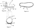
- FIG. 16 depicts a side view of a ski boot lower shell according to a fourth embodiment of the invention.
- FIG. 17 depicts a front view in cross section on a vertical plane at the front part of the ski boot lower shell according to the fourth embodiment of the invention.
- FIG. 18 depicts a plan view in section on a horizontal plane at the upper part of the ski boot lower shell according to the fourth embodiment of the invention.
- FIG. 19 depicts a side view of a ski boot cuff according to a first embodiment of the invention.
- FIG. 20 depicts a rear view of the ski boot cuff according to the first embodiment of the invention.
- FIG. 21 depicts a side view in section on a vertical mid-plane of the ski boot cuff according to the first embodiment of the invention.
- FIG. 22 depicts a plan view in section on a horizontal plane of the ski boot cuff according to the first embodiment of the invention.
- FIG. 23 depicts a side view of a ski boot cuff according to a second embodiment of the invention.
- FIG. 24 depicts a rear view of the ski boot cuff according to the second embodiment of the invention.
- FIG. 25 depicts a side view in section on a vertical mid-plane of the ski boot cuff according to the second embodiment of the invention.
- FIG. 26 depicts a plan view in section on a horizontal plane at the bottom part of the ski boot cuff according to the second embodiment of the invention.
- FIG. 27 depicts a side view of a ski boot cuff according to a third embodiment of the invention.
- FIG. 28 depicts a rear view of the ski boot cuff according to the third embodiment of the invention.
- FIG. 29 depicts a side view in section on a vertical mid-plane of the ski boot cuff according to the third embodiment of the invention.
- FIG. 30 depicts a plan view in section on a horizontal plane at the top of the ski boot cuff according to the third embodiment of the invention.
- FIG. 31 depicts a plan view in section on a horizontal plane at the bottom part of the ski boot cuff according to the third embodiment of the invention.
- FIG. 32 depicts a front perspective view of the ski boot cuff according to the first embodiment of the invention.
- the vertical direction refers to the direction from the bottom upwards, namely from the sole of the boot towards the top of the boot.
- the horizontal direction refers to the direction perpendicular to the vertical direction, parallel to a plane on which the sole of the boot rests.
- the external face of a boot element will refer to its surface facing towards the outside of the boot and the internal face will refer to a surface oriented towards the inside of the boot, on the side of the foot.
- FIG. 1 illustrates an alpine ski boot 1 according to one embodiment of the invention, which comprises a rigid outer shell formed of several injection moulded plastics materials as will be detailed hereinbelow, notably comprising two elements: a cuff 2 articulated to a lower shell 3 about a hinge 4 .
- the lower shell 3 extends from the outsole 6 up to the hinge 4 that hinges and connects it to the cuff 2 in the vertical direction.
- a comfort inner boot 5 is inserted into the rigid shell.
- the sole 6 is extended towards its two, front and rear ends by side walls at boot toe and side walls at boot heel, called in a more simple way curb 7 (or lip), of a format suited to collaborating with the jaws of a ski boot binding device.
- curb 7 or lip
- a boot element such as, for example, a lower shell 3 or a cuff 2 of a ski boot, which comprises at least two injection-moulding steps using a co-injection moulding principle to inject two different plastics materials respectively.
- Different refers to materials having different mechanical characteristics, such as, for example, different Young's modulus values, and/or different hardnesses. As an alternative or in addition, this difference may be visible, the two materials then being different colours.
- the method used here is a co-injection moulding method in which at least two plastics materials are injected into the same mould, via at least one same injection point through which at least two different materials pass in succession.
- These two materials are, in particular, plastics materials, possibly fibre-reinforced plastics materials, for example glass-fibre-reinforced, carbon-fibre-reinforced, etc. materials.
- Co-injection moulding relies on at least two successive steps of injecting plastics materials into a single mould, these two steps being sufficiently close together that the second material injected through the first material injected imbricates therein.
- the first material 15 is injected into the mould. It remains sufficiently fluid at the time of injection of the second material 16 through the first material into the same mould, notably at the internal surface thereof which remains hotter for longer than its external surfaces, which cool more quickly in contact with the walls of the injection mould.
- the imbrication mentioned manifests itself in two ways. First, the second injected material partially penetrates the layer formed by the first material injected with the first injection.
- the second material penetrates across the internal surface of this mentioned layer under the effect of the significant energy imparted as it is injected and spreads into the thickness of the first layer, finally forming a so-called “sandwich” wall zone in which the second material injected is enclosed between two layers of the first material injected.
- the second material injected carries part of the first material of the first injection beyond the position it reached at the time of the first injection, as far as a frontier (limit, boundary, border) zone where the two materials are substantially mixed and alternated, before the second material continues on its way alone beyond this frontier zone. This then creates a frontier zone or intermediate zone between the two materials which has no clean or linear frontier.
- the first material may form “flame” shapes in a direction defined by the direction of injection of the second material, at the frontier beyond which the first material injected disappears.
- the second material may in isolated points reach the external walls of the element possibly alternating with the first material.
- the first material could at isolated points partially penetrate the central part of the second material.
- the position of the frontier zone may fluctuate by approximately one centimetre.
- FIG. 2 illustrates a ski boot lower shell 3 obtained according to one embodiment of the invention, similar to the second embodiment described later on in conjunction with FIGS. 7 to 10 .
- the two materials used are depicted in the figures as two different colours, respectively dark and white, and can both be seen on the external face of the lower shell. These two materials constitute the wall of the lower shell 3 but are distributed in a particular way on the external and internal faces of the lower shell, and in the thickness of the wall.
- the first material occupies the external face of the lower shell
- a front second zone 13 the second material occupies the external face of the lower shell.
- the frontier 14 between the two zones 11 , 13 is not clean, has discontinuities and/or a form or a line with significant non-smooth fluctuations or irregularities thus delimiting a surface on each side that is not completely convex or concave.
- the intermediate zone 12 at the frontier 14 comprises a mixture of the two materials, the effect of this being passed on in the form of a zone of intermediate and fluctuating rigidity or of a degraded colour and/or of a random alternation between the two colours.
- the zones 11 , 12 , 13 could occupy any other surface of the lower shell.
- the first zone 11 consists of a “sandwich” type wall which contains the second material (depicted as white) intercalated between two layers of the first material (depicted as dark).
- This first material constitutes the two, external and internal, faces of the wall of the lower shell 3 which respectively form the exterior face of the shell and the interior face of the shell situated facing the foot. Comment: the second material is therefore not visible from the outside and from the inside of the lower shell in the first zone 11 because it is contained between two layers formed of the first material injected.
- the second zone 13 comprises only the second material throughout the thickness of the wall of the lower shell, and therefore becomes visible both from the outside and from the inside of this zone of the lower shell 3 .
- the temperature of the injection mould is raised between 50 and 60° C. during the injections.
- the time between the two injections is comprised between 3 and 6 seconds, advantageously 4 or 5 seconds. This time can be lengthened if the temperature of the mould increases, or conversely may be shortened if it decreases.
- the two successive injections need to be performed at the same point in the mould, from one and the same injection point.
- a traditional injection-moulding machine with two injection nozzles is used.
- the other injection points may receive either the injection of just one of the two materials or the two successive injections, according to the co-injection moulding technique.
- the first material is injected first of all via the two injection points, then the second material is injected in its turn via the same two injection points, through the first material injected.
- the embodiment depicted in FIG. 2 can be obtained by two injection points positioned at two different heights in the rear zone of the lower shell, each one receiving the two successive injections according to the co-injection moulding technique explained hereinabove.
- the second material therefore extends continuously from the rear end of the first zone 11 to the front end of the second zone 13 , but is not visible on the lower shell 3 except in the second zone 13 .
- the two materials used in the manufacturing method are different. This difference may become apparent as a result of different colours, in order to obtain the visual effect explained hereinabove in conjunction with FIG. 2 .
- the term “colour” is to be interpreted in the broad sense, namely to refer to any particular aspect, including a transparent or translucent appearance.
- two materials of different rigidities are used in order to obtain a wall the rigidity of which varies according to the zones of the boot element, in order to achieve a compromise chosen according to the performance and comfort requirements recalled hereinabove for the boot element. Comment: these two materials of different rigidities may or may not be of different colours.
- the first material is more rigid than the second and is preferably positioned in those zones of the boot element that require greater rigidity: these zones will be detailed in the examples described later on.
- the second material is more flexible and will be the only material found in the zones requiring greater flexibility.
- the difference in rigidity between the two materials is greater than or equal to 5 ShD.
- the first material may be polyurethane with a hardness comprised between 50 and 70 ShD inclusive, preferably between 55 and 60 ShD inclusive, or any other plastics material of equivalent hardness
- the second material may be polyurethane with a hardness comprised between 40 and 60 ShD inclusive, preferably between 45 and 50 ShD inclusive, or any other plastics material of equivalent hardness.
- the two materials may be identical but preferably of different hardness, or may be different.
- the first material may be polyurethane and the second polyamide or a polyether block amide.
- the plastics material used may be different, such as a polyolefin.
- the zone comprising a “sandwich” type wall of the boot element has the particular feature of having a hardness that varies according to the thickness of the wall, notably having an intermediate part that is not as hard as the two, internal and external, layers of the sandwich in the case where the first material injected is more rigid than the second.
- the quantity of each of the two materials used is not arbitrary. Specifically, the quantity of first material injected needs to be less than the quantity at which the first material would occupy the entire surface or almost the entire surface of the mould, in which case the second material injected would be unable to reach the external faces of the wall in the second zone, and in which case the first material would impose a relatively constant rigidity on the wall of the boot or in any case a rigidity that varied over a range markedly smaller than that desired by the invention.
- the quantity of first material injected is such that it does not extend over the entire surface of the injection-moulded element, and preferably extends over less than 75%, or even less than 50%, of the surface of the injection-moulded element.
- one advantageous embodiment is to inject a quantity of first material representing by weight 50% or less of the total weight of the boot element after it has been finalized, or even 40% or less or 30% or less of this total weight.
- the second injection of the second material may then make up all of the remaining weight, or even just part of this weight if more than two injected materials are planned.
- the first material injected is depicted in a dark colour and is more rigid and harder than the second.
- the first and second materials may be chosen to be the same colour or to be different colours.
- the first and second zones may be produced in different parts of the boot.
- the frontier 14 is represented by a line that has been smoothed for the sake of simplicity, something which is not entirely true to life as explained earlier.
- FIGS. 3 to 18 illustrate several embodiments of a ski boot lower shell and FIGS. 19 to 32 depict several embodiments of a ski boot cuff.
- FIGS. 3 to 6 illustrate a first embodiment of a ski boot lower shell 3 .
- the first zone 11 comprising the “sandwich” wall particularly visible in the sections of FIGS. 4 and 5 in which the two materials 15 , 16 can be distinguished, extends at the rear part of the lower shell.
- the second material 16 is present in the central part of the sandwich, the first material 15 forming the two outer layers of the sandwich, the two, internal and external, faces of the wall of the lower shell. It allows the creation of a wall that is rigid, because of the presence of the first material 15 injected, which guarantees firm retention of the skier's foot and gives the boot sufficient rigidity in the rear part thereof.
- the frontal part notably in the region of the instep, is obtained by two flaps 9 of a material that is more flexible because these are formed only by the second material 16 injected as illustrated in FIG. 4 .
- two injection points 17 , 18 arranged at two different heights of the rear part of the lower shell are used. These two injection points receive the two materials in succession.
- a fourth zone 23 in the wall of the boot comprising only the first material injected may exist, as illustrated in FIG. 5 .
- This zone is situated near the upper end of the lower shell, which is of very small thickness. This is achieved because the mould is not very thick at this point and the first material injected cools quickly in contact with the walls of the mould thus preventing the second material from penetrating into the first material.
- a “sole” the lower part of the lower shell that forms at least part of the future outsole of the ski boot. In general, this sole will be supplemented by the addition of additional components to form the final structure of the outsole of the boot.
- FIGS. 7 to 10 illustrate a second embodiment in which the first material extends as far as the lower part of the lower shell and also forms the rear curb of the boot and forms the sandwich structure in combination with the second material. It is obtained with two injection points 17 , 18 still situated at the rear part of the lower shell, and with possibly an injection point 19 situated under the sole of the lower shell near the heel, and a quantity of first material 15 that is greater than the quantity used in the previous embodiment.
- FIGS. 11 to 13 illustrate a third embodiment in which the first material 15 present in the first zone 11 extends in the lower part of the lower shell and notably comprises the entire sole of the lower shell.
- This first zone 11 comprises the sandwich structure formed by the complex consisting of the first material—second material—first material, as explained hereinabove.
- this first material 15 is more rigid and forms the curbs 7 .
- the rigidity of the materials will be chosen in order to achieve a hardness for the curbs 7 of the outsole 6 that is greater than 45 ShD for children and greater than 50 ShD for adults.
- the sole is obtained with four injection points 19 , 20 , 21 , 22 situated under the sole, or even by five injection points.
- the entirety of the upper part of the lower shell situated above the first zone 11 forms the second zone 13 and is made up of a single-material wall made of the second material 16 .
- FIGS. 14 and 15 illustrate an alternative form of the third embodiment.
- the more rigid first material 15 also extends in the lower part of the lower shell, but in a smaller quantity, so that it does not extend over the entire length of the lower shell. It is precisely concentrated into the front and rear curbs 7 , and into the central part, at the zone 11 , which appears discontinuous under the sole of the lower shell (when discounting any toe piece and heel piece there might be) and along the length of the boot.
- the rigid first material 15 can be seen from the outside of the boot and forms the walls of the sandwich as explained earlier.
- zones 11 , 13 which means to say of rigid and flexible zones.
- This approach makes it possible to stiffen the zones of the lower shell which are particularly highly stressed, without excessively altering the characteristics of the lower shell.
- This alternative form is manufactured using three injection points 19 , 20 , 22 situated under the sole, one point 19 , 22 at each curb and another point 20 in the central part.
- the first injection allows a small quantity of rigid material 15 to be injected whereas the second injection makes it possible to inject the more flexible material 16 in greater quantity.
- the sandwich rigid part may be confined only to the curb region: in that case, two injection points 19 , 22 , one at each curb, may suffice.
- more than three injection points may be used, in order to achieve a similar result.
- FIGS. 16 to 18 illustrate a fourth embodiment which corresponds to the combination of the first or second embodiments with the third.
- the first material 15 present in the first zone 11 extends into the lower and rear parts of the lower shell.
- This lower shell is obtained using two injection points 17 , 18 situated in the rear part of the lower shell and four injection points 19 , 20 , 21 , 22 situated under the sole of the lower shell.
- the most flexible part formed in the second zone 13 by the second material 16 is located only in the region of the flaps 9 in order to make the boot easier to put on.
- FIGS. 19 to 22 and 32 illustrate a first embodiment of a ski boot cuff intended to surround and grip the lower leg of the user.
- the cuff is made up of a rear part extended at the front by two flaps 25 intended to be superposed and to flap around the front of the skier's leg.
- This cuff is made up of zones of variable rigidity.
- This cuff has a rear surface, visible in FIG. 20 , over which there extends the first zone 11 which is formed by a sandwich-type wall made up of a multilayer composed, from the outside towards the inside of the wall, of the rigid material 15 , of the flexible material 16 , and of some more rigid material 15 again.
- This first zone is extended by the two lateral flaps 25 .
- the anterior part of these flaps 25 is more flexible and contains only the second material 16 .
- the rigid first zone 11 also extends to the hinges 4 of the cuff. This cuff is obtained using three injection points 26 , 27 , 28 situated in the rear part of the cuff.
- FIGS. 23 to 26 illustrate a second embodiment of a ski boot cuff.
- This second embodiment still comprises the first zone 11 at the rear part of the cuff but it does not extend as far as the bottom of the cuff.
- This cuff is obtained with an injection point 26 situated at the rear part of the cuff.
- a view in section of the upper part of this second embodiment of a cuff is the one illustrated in FIG. 23 .
- FIGS. 27 to 31 illustrate a third embodiment of a ski boot cuff.
- This third embodiment still comprises the first zone 11 at the rear part of the cuff but it extends only in the lower part of the cuff, not all the way up to the top of the cuff. Comment: the rigid first zone 11 also extends to the hinges 4 of the cuff.
- This cuff is obtained with an injection point 28 situated in the rear part of the cuff.
- the invention advantageously makes it possible to obtain a cuff that has two distinct zones of different rigidities so as to optimize a flexible part located in the region of the flaps 25 to favour putting the boot on and comfort, and a more rigid rear zone that holds the leg firmly and prevents the cuff from deforming backwards when moving around on skis.
- the various envisaged injection points receive two successive injections according to the principle of co-injection moulding.
- the first material is injected simultaneously through the various injection points and then, after a very short space of time, the second material is injected simultaneously through the same injection points in order to achieve the co-injection.
- the co-injection may be used on at least one injection point, the other injection points then receiving only one injected material alone, or permit the use of any other injection-moulding technique known from the prior art.
- the invention also relates to an element or boot of which the wall comprises at least two different plastics materials, of which a first zone 11 , comprising the two different plastics materials within its thickness, the first plastics material occupying the external face of the wall, visible from the outside of the boot element and the second plastics material being intercalated between two layers of the first plastics material, and a second zone 13 containing only the second plastics material.
- the first zone 11 therefore contains the first plastics material 15 forming two layers of the wall, constituting the internal and external faces of the said wall, and the second plastics material 16 is interposed between the two layers of the first plastics material 15 . Comment: the second material 16 extends continuously from the first zone 11 to the second zone 13 , within the wall of the element, even though it is not visible at the first zone.
- the boot element comprises an intermediate third zone in which the two materials are mixed, appearing alternately and irregularly, or in a mixed manner, on the visible external surface of the wall of the element.
- This intermediate third zone is situated between the first zone consisting of a sandwich structure and the second zone consisting only of the second material.
- the element may comprise a fourth zone in which the wall contains only the first material, located in particular around the thin edges of the element.
- the boot element may comprise more than two injected plastics materials, a third material for example being injection overmoulded onto the co-injection moulded assembly described above.
- three materials could be co-injection moulded to form a zone made up of a sandwich formed of five layers, then a zone made up of a sandwich formed of three layers, followed by a single-material zone, this single-material zone forming the central part of each of the sandwiches.
- Embodiments comprising N materials may be envisaged according to the same principle.
- the concept of the invention may of course be implemented for any boot element, of the lower shell or cuff type as described, but also for the sole, strap or buckle arrangement, tongue intended for a shell or for a comfort inner boot, heel reinforcement for a cross-country skiing ski boot, or other plastic components which require, in places, either high rigidity or good flexibility.
- the flexible part would preferably be positioned in the lower part of the tongue, in the instep region, and therefore formed by the second material, while the more rigid upper part in the region of the shin would be formed by the sandwich made up of the first and second materials.
- the invention also relates to any sports shoe or boot incorporating such an element. This sports shoe or boot may be any item of footwear for a sliding sport, such as a ski boot, an ice skate, etc.
- the method according to the invention advantageously makes it possible to manufacture a series of sports boots of different appearances, making it possible in particular to see the zones of different rigidity of the boot.
- the invention has been described in connection with the use of a first material that is more rigid than the second material, but the reverse may be envisaged for creating new elements.
- the method according to the invention advantageously makes it possible to manufacture a series of sports boots with a different level of performance using one and the same mould, because all that is required is a minor modification to the co-injection moulding parameters and in particular to the quantities of first and second material and/or the materials chosen in order to obtain a multitude of results that differ from the viewpoint of rigidity.
- the mould may be locally heated in order to keep the materials injected in a fluid state and better control their distribution through the element. Conversely, it is possible for the mould to be cooled locally.
- the invention thus makes it possible to increase the rigidity of certain zones that require high rigidity, while at the same time maintaining a good level of flexibility in other zones. This then yields boot elements exhibiting the best compromise between rigidity and flexibility.
Landscapes
- Engineering & Computer Science (AREA)
- Mechanical Engineering (AREA)
- Health & Medical Sciences (AREA)
- General Health & Medical Sciences (AREA)
- Physical Education & Sports Medicine (AREA)
- Manufacturing & Machinery (AREA)
- Chemical & Material Sciences (AREA)
- Materials Engineering (AREA)
- Footwear And Its Accessory, Manufacturing Method And Apparatuses (AREA)
Abstract
Description
-
- a first zone comprising two different plastics materials within its thickness, the first plastics material forming two layers of the wall constituting the internal and external faces of the said wall, and the second plastics material being interposed between the two layers of the first plastics material, and
- a second zone comprising only the second plastics material.
-
- co-injection moulding makes it possible to obtain a result that is satisfactory in terms of performance, forming flexible parts and rigid parts in chosen zones of the wall of a sports boot element;
- it also makes it possible to obtain original, varied and attractive aesthetic appearances;
- it can be implemented easily, allowing the rapid and low-cost manufacture of a sports boot element, particularly by reducing the number of injection moulds used.
Claims (26)
Applications Claiming Priority (3)
| Application Number | Priority Date | Filing Date | Title |
|---|---|---|---|
| EP15425042.7 | 2015-06-11 | ||
| EP15425042.7A EP3103630B2 (en) | 2015-06-11 | 2015-06-11 | Co-injected sports shoe |
| EP15425042 | 2015-06-11 |
Publications (2)
| Publication Number | Publication Date |
|---|---|
| US20160360823A1 US20160360823A1 (en) | 2016-12-15 |
| US11219269B2 true US11219269B2 (en) | 2022-01-11 |
Family
ID=53794180
Family Applications (1)
| Application Number | Title | Priority Date | Filing Date |
|---|---|---|---|
| US15/178,662 Active 2037-12-31 US11219269B2 (en) | 2015-06-11 | 2016-06-10 | Co-injection moulded sports boot |
Country Status (2)
| Country | Link |
|---|---|
| US (1) | US11219269B2 (en) |
| EP (1) | EP3103630B2 (en) |
Families Citing this family (8)
| Publication number | Priority date | Publication date | Assignee | Title |
|---|---|---|---|---|
| EP3673761B1 (en) * | 2018-12-27 | 2021-08-11 | Rossignol Lange S.R.L. | Cross-country ski boot element obtained by co-injection |
| US12539682B2 (en) | 2019-03-13 | 2026-02-03 | Ecco Sko A/S | Moulding system for direct injection manufacturing of footwear |
| CN113573606A (en) | 2019-03-13 | 2021-10-29 | 伊科斯克有限公司 | System for manufacturing a mold-based apparatus for direct injection production of footwear and method of manufacturing footwear |
| CN118269396A (en) * | 2019-03-13 | 2024-07-02 | 伊科斯克有限公司 | Footwear injection mold |
| US12478130B2 (en) | 2019-08-19 | 2025-11-25 | Ecco Sko A/S | Footwear injection mould |
| IT202300025617A1 (en) * | 2023-11-30 | 2025-05-30 | Plastimedia S R L | SIMULTANEOUS MOULDING METHOD AND RELATED MOULDED PRODUCT |
| US12501967B2 (en) * | 2024-04-19 | 2025-12-23 | Skechers U.S.A., Inc. Ii | Hands-free molded shoe |
| US20250351918A1 (en) * | 2024-05-16 | 2025-11-20 | Vh Footwear Inc. | Skate boot with stiffening cuff insert |
Citations (11)
| Publication number | Priority date | Publication date | Assignee | Title |
|---|---|---|---|---|
| US3950483A (en) * | 1972-03-02 | 1976-04-13 | I Martin Spier | Injection molding process |
| US4245410A (en) * | 1979-05-14 | 1981-01-20 | Questor Corporation | Foamed ski boot |
| US4907353A (en) * | 1987-01-23 | 1990-03-13 | Tmc Corporation | Cross-country ski boot |
| JPH02126801A (en) | 1988-11-05 | 1990-05-15 | Moon Star Co | Injection-molded shoe having multi-layer sole |
| US5667737A (en) * | 1991-01-28 | 1997-09-16 | Koflach Sport Gesellschaft M.B.H. & Co. Kg | Method of manufacturing an injection molded shoe |
| EP0823323A1 (en) | 1996-08-08 | 1998-02-11 | Benetton Sportsystem S.p.A. | Coinjection method for plastic components, particularly for shoes |
| CA2374148A1 (en) | 1999-06-02 | 2000-12-07 | Vans, Inc. | Sports shoe interface |
| US6457265B1 (en) * | 1997-09-09 | 2002-10-01 | Lange International S.A. | Sport boot |
| US20050081408A1 (en) * | 2002-04-26 | 2005-04-21 | Salomon S.A. | Boot having a flexible outer wall |
| US20060064904A1 (en) * | 2004-09-29 | 2006-03-30 | Emanuele Confortin | Sports boot in very stiff material |
| WO2014136051A1 (en) | 2013-03-04 | 2014-09-12 | Bazzani Andrea | Shell for ski boots |
Family Cites Families (7)
| Publication number | Priority date | Publication date | Assignee | Title |
|---|---|---|---|---|
| IT232699Y1 (en) | 1994-01-21 | 2000-01-19 | Lange Int Sa | PLASTIC SKI BOOT, AT LEAST ONE PART OF WHICH IS CONSISTING OF TWO DIFFERENT PLASTIC MATERIALS |
| JPH0976291A (en) | 1995-09-20 | 1997-03-25 | Japan Steel Works Ltd:The | Molding method and molding die for molded article made of different materials |
| JP3497301B2 (en) | 1995-11-08 | 2004-02-16 | 本田技研工業株式会社 | Method for producing synthetic resin molded article |
| US5595799A (en) | 1995-12-14 | 1997-01-21 | Dtl Technology Limited Partnership | Coinjection molding of decorative preforms and containers produced from such preforms |
| ITMI20020593A1 (en) | 2002-03-20 | 2003-09-22 | Enrico Scarabelli | PROCEDURE FOR INJECTION MOLDING OF PRODUCTS IN AT LEAST TWO DISTINCT MATERIALS |
| DE102005034081A1 (en) | 2005-07-21 | 2007-01-25 | Uvex Arbeitsschutz Gmbh | Method for producing a spectacle arm |
| EP2554353B1 (en) | 2011-08-05 | 2017-06-07 | Trisa Holding AG | Tooth brush and method for the manufacture of a tooth brush |
-
2015
- 2015-06-11 EP EP15425042.7A patent/EP3103630B2/en active Active
-
2016
- 2016-06-10 US US15/178,662 patent/US11219269B2/en active Active
Patent Citations (12)
| Publication number | Priority date | Publication date | Assignee | Title |
|---|---|---|---|---|
| US3950483A (en) * | 1972-03-02 | 1976-04-13 | I Martin Spier | Injection molding process |
| US4245410A (en) * | 1979-05-14 | 1981-01-20 | Questor Corporation | Foamed ski boot |
| US4907353A (en) * | 1987-01-23 | 1990-03-13 | Tmc Corporation | Cross-country ski boot |
| JPH02126801A (en) | 1988-11-05 | 1990-05-15 | Moon Star Co | Injection-molded shoe having multi-layer sole |
| US5667737A (en) * | 1991-01-28 | 1997-09-16 | Koflach Sport Gesellschaft M.B.H. & Co. Kg | Method of manufacturing an injection molded shoe |
| EP0823323A1 (en) | 1996-08-08 | 1998-02-11 | Benetton Sportsystem S.p.A. | Coinjection method for plastic components, particularly for shoes |
| US6457265B1 (en) * | 1997-09-09 | 2002-10-01 | Lange International S.A. | Sport boot |
| CA2374148A1 (en) | 1999-06-02 | 2000-12-07 | Vans, Inc. | Sports shoe interface |
| US20010001909A1 (en) | 1999-06-02 | 2001-05-31 | Vans, Inc. | Sports shoe interface |
| US20050081408A1 (en) * | 2002-04-26 | 2005-04-21 | Salomon S.A. | Boot having a flexible outer wall |
| US20060064904A1 (en) * | 2004-09-29 | 2006-03-30 | Emanuele Confortin | Sports boot in very stiff material |
| WO2014136051A1 (en) | 2013-03-04 | 2014-09-12 | Bazzani Andrea | Shell for ski boots |
Non-Patent Citations (1)
| Title |
|---|
| European Search Report and Written Opinion dated Dec. 10, 2015 issued in counterpart application No. EP15425042; w/ English partial translation and partial machine translation (11 pages). |
Also Published As
| Publication number | Publication date |
|---|---|
| EP3103630B1 (en) | 2020-12-09 |
| US20160360823A1 (en) | 2016-12-15 |
| EP3103630B2 (en) | 2025-11-19 |
| EP3103630A1 (en) | 2016-12-14 |
Similar Documents
| Publication | Publication Date | Title |
|---|---|---|
| US11219269B2 (en) | Co-injection moulded sports boot | |
| US9700103B2 (en) | Cleated footwear with flexible cleats | |
| US12290143B2 (en) | Skate or other footwear | |
| CA1039945A (en) | Method of manufacture of shoes and shoes thus manufactured | |
| US9591889B2 (en) | Foot support structure and articles incorporating same | |
| US20160227873A1 (en) | Sole for a shoe | |
| US20120279089A1 (en) | Method for fabricating a footwear sole | |
| CN103783717B (en) | For ski boots substrate and include the ski boots of this substrate | |
| US20090307930A1 (en) | Innerboot for a sports boot | |
| WO2007100451A1 (en) | Flexible foot-support structures and products containing such support structures | |
| KR20020033776A (en) | Sole in the form of a midsole, inner sole or insertable sole for a shoe and a shoe with said sole | |
| US20120311890A1 (en) | Footwear with improved upper | |
| US20140013630A1 (en) | Shoe for practicing sports involving gliding over the snow or for walking | |
| US20070107257A1 (en) | Multi-material molded shell for footwear | |
| EP1444908B1 (en) | Article of footwear having at least partially composite structure | |
| WO2013058658A1 (en) | Outer sole for ski boot | |
| KR101778534B1 (en) | Dancesport shoes and manufacturing method thereof | |
| US20050161909A1 (en) | Children's board for gliding over snow and manufacturing method | |
| CN2371833Y (en) | Football boots capable of producing loop spin ball path | |
| CN209610021U (en) | Multi-hardness sole blank and sole | |
| US20260047636A1 (en) | Skate or other footwear | |
| CN108813804A (en) | Multi-hardness sole blank and sole | |
| EP2591691A1 (en) | Sports footwear such as a ski boot or suchlike | |
| CA2761200A1 (en) | Method for fabricating a footwear sole | |
| ITPD970145A1 (en) | TITANIUM FOOTBED WITH SHOE RIBS |
Legal Events
| Date | Code | Title | Description |
|---|---|---|---|
| AS | Assignment |
Owner name: ROSSIGNOL LANGE S.R.L., ITALY Free format text: ASSIGNMENT OF ASSIGNORS INTEREST;ASSIGNORS:GARBUJO, GIUSEPPE;POSATO, TIZIANO;POLONI, MASSIMO;AND OTHERS;REEL/FRAME:038997/0087 Effective date: 20160614 |
|
| STPP | Information on status: patent application and granting procedure in general |
Free format text: RESPONSE TO NON-FINAL OFFICE ACTION ENTERED AND FORWARDED TO EXAMINER |
|
| STPP | Information on status: patent application and granting procedure in general |
Free format text: FINAL REJECTION MAILED |
|
| STPP | Information on status: patent application and granting procedure in general |
Free format text: ADVISORY ACTION MAILED |
|
| STPP | Information on status: patent application and granting procedure in general |
Free format text: DOCKETED NEW CASE - READY FOR EXAMINATION |
|
| STPP | Information on status: patent application and granting procedure in general |
Free format text: NON FINAL ACTION MAILED |
|
| STPP | Information on status: patent application and granting procedure in general |
Free format text: FINAL REJECTION MAILED |
|
| STPP | Information on status: patent application and granting procedure in general |
Free format text: RESPONSE AFTER FINAL ACTION FORWARDED TO EXAMINER |
|
| STPP | Information on status: patent application and granting procedure in general |
Free format text: ADVISORY ACTION MAILED |
|
| STPP | Information on status: patent application and granting procedure in general |
Free format text: DOCKETED NEW CASE - READY FOR EXAMINATION |
|
| STPP | Information on status: patent application and granting procedure in general |
Free format text: NON FINAL ACTION MAILED |
|
| STPP | Information on status: patent application and granting procedure in general |
Free format text: RESPONSE TO NON-FINAL OFFICE ACTION ENTERED AND FORWARDED TO EXAMINER |
|
| STPP | Information on status: patent application and granting procedure in general |
Free format text: NOTICE OF ALLOWANCE MAILED -- APPLICATION RECEIVED IN OFFICE OF PUBLICATIONS |
|
| STPP | Information on status: patent application and granting procedure in general |
Free format text: AWAITING TC RESP., ISSUE FEE NOT PAID |
|
| STPP | Information on status: patent application and granting procedure in general |
Free format text: NOTICE OF ALLOWANCE MAILED -- APPLICATION RECEIVED IN OFFICE OF PUBLICATIONS |
|
| STPP | Information on status: patent application and granting procedure in general |
Free format text: PUBLICATIONS -- ISSUE FEE PAYMENT VERIFIED |
|
| STCF | Information on status: patent grant |
Free format text: PATENTED CASE |
|
| MAFP | Maintenance fee payment |
Free format text: PAYMENT OF MAINTENANCE FEE, 4TH YEAR, LARGE ENTITY (ORIGINAL EVENT CODE: M1551); ENTITY STATUS OF PATENT OWNER: LARGE ENTITY Year of fee payment: 4 |