US11219161B2 - Hand-propelled power tool - Google Patents
Hand-propelled power tool Download PDFInfo
- Publication number
- US11219161B2 US11219161B2 US16/922,118 US202016922118A US11219161B2 US 11219161 B2 US11219161 B2 US 11219161B2 US 202016922118 A US202016922118 A US 202016922118A US 11219161 B2 US11219161 B2 US 11219161B2
- Authority
- US
- United States
- Prior art keywords
- connecting rod
- adjusting assembly
- main body
- assembly
- rotation
- Prior art date
- Legal status (The legal status is an assumption and is not a legal conclusion. Google has not performed a legal analysis and makes no representation as to the accuracy of the status listed.)
- Active
Links
Images


Classifications
-
- A—HUMAN NECESSITIES
- A01—AGRICULTURE; FORESTRY; ANIMAL HUSBANDRY; HUNTING; TRAPPING; FISHING
- A01D—HARVESTING; MOWING
- A01D34/00—Mowers; Mowing apparatus of harvesters
- A01D34/01—Mowers; Mowing apparatus of harvesters characterised by features relating to the type of cutting apparatus
- A01D34/412—Mowers; Mowing apparatus of harvesters characterised by features relating to the type of cutting apparatus having rotating cutters
- A01D34/63—Mowers; Mowing apparatus of harvesters characterised by features relating to the type of cutting apparatus having rotating cutters having cutters rotating about a vertical axis
- A01D34/82—Other details
- A01D34/824—Handle arrangements
-
- B—PERFORMING OPERATIONS; TRANSPORTING
- B25—HAND TOOLS; PORTABLE POWER-DRIVEN TOOLS; MANIPULATORS
- B25F—COMBINATION OR MULTI-PURPOSE TOOLS NOT OTHERWISE PROVIDED FOR; DETAILS OR COMPONENTS OF PORTABLE POWER-DRIVEN TOOLS NOT PARTICULARLY RELATED TO THE OPERATIONS PERFORMED AND NOT OTHERWISE PROVIDED FOR
- B25F5/00—Details or components of portable power-driven tools not particularly related to the operations performed and not otherwise provided for
- B25F5/02—Construction of casings, bodies or handles
-
- A—HUMAN NECESSITIES
- A01—AGRICULTURE; FORESTRY; ANIMAL HUSBANDRY; HUNTING; TRAPPING; FISHING
- A01D—HARVESTING; MOWING
- A01D34/00—Mowers; Mowing apparatus of harvesters
-
- A—HUMAN NECESSITIES
- A01—AGRICULTURE; FORESTRY; ANIMAL HUSBANDRY; HUNTING; TRAPPING; FISHING
- A01D—HARVESTING; MOWING
- A01D34/00—Mowers; Mowing apparatus of harvesters
- A01D34/01—Mowers; Mowing apparatus of harvesters characterised by features relating to the type of cutting apparatus
- A01D34/412—Mowers; Mowing apparatus of harvesters characterised by features relating to the type of cutting apparatus having rotating cutters
- A01D34/63—Mowers; Mowing apparatus of harvesters characterised by features relating to the type of cutting apparatus having rotating cutters having cutters rotating about a vertical axis
- A01D34/67—Mowers; Mowing apparatus of harvesters characterised by features relating to the type of cutting apparatus having rotating cutters having cutters rotating about a vertical axis hand-guided by a walking operator
- A01D34/68—Mowers; Mowing apparatus of harvesters characterised by features relating to the type of cutting apparatus having rotating cutters having cutters rotating about a vertical axis hand-guided by a walking operator with motor driven cutters or wheels
-
- B—PERFORMING OPERATIONS; TRANSPORTING
- B25—HAND TOOLS; PORTABLE POWER-DRIVEN TOOLS; MANIPULATORS
- B25F—COMBINATION OR MULTI-PURPOSE TOOLS NOT OTHERWISE PROVIDED FOR; DETAILS OR COMPONENTS OF PORTABLE POWER-DRIVEN TOOLS NOT PARTICULARLY RELATED TO THE OPERATIONS PERFORMED AND NOT OTHERWISE PROVIDED FOR
- B25F5/00—Details or components of portable power-driven tools not particularly related to the operations performed and not otherwise provided for
-
- E—FIXED CONSTRUCTIONS
- E01—CONSTRUCTION OF ROADS, RAILWAYS, OR BRIDGES
- E01H—STREET CLEANING; CLEANING OF PERMANENT WAYS; CLEANING BEACHES; DISPERSING OR PREVENTING FOG IN GENERAL CLEANING STREET OR RAILWAY FURNITURE OR TUNNEL WALLS
- E01H5/00—Removing snow or ice from roads or like surfaces; Grading or roughening snow or ice
- E01H5/04—Apparatus propelled by animal or engine power; Apparatus propelled by hand with driven dislodging or conveying levelling elements, conveying pneumatically for the dislodged material
-
- A—HUMAN NECESSITIES
- A01—AGRICULTURE; FORESTRY; ANIMAL HUSBANDRY; HUNTING; TRAPPING; FISHING
- A01D—HARVESTING; MOWING
- A01D2101/00—Lawn-mowers
-
- B—PERFORMING OPERATIONS; TRANSPORTING
- B62—LAND VEHICLES FOR TRAVELLING OTHERWISE THAN ON RAILS
- B62B—HAND-PROPELLED VEHICLES, e.g. HAND CARTS OR PERAMBULATORS; SLEDGES
- B62B5/00—Accessories or details specially adapted for hand carts
- B62B5/06—Hand moving equipment, e.g. handle bars
- B62B5/064—Hand moving equipment, e.g. handle bars adaptable for different users, e.g. by means of pivoting elements
Definitions
- the present disclosure relates to a hand-propelled power tool.
- the hand-propelled power tool can be operated by a user to do trimming of the garden.
- hand-propelled tools they include a lawn mower, a snow blower, etc.
- the lawnmower includes a handle assembly connected to the main body of the lawnmower.
- the handle assembly is generally composed of two connecting rods, and the relative angle between the handle assembly and the main body needs to be adjusted in a timely manner.
- an operator operates the handle assembly typically he needs to release or lock the handle assembly.
- due to vibration and strain during the process of assembly, operation, etc. the reliability of the locked or released state between the handle assembly and the main body is reduced, even making locking or releasing impossible.
- a hand-propelled power tool includes a main body; a handle assembly comprising a gripping portion, a first connecting rod and a second connecting rod, wherein the gripping portion includes a first end and a second end, a first connecting rod connects the first end of the gripping portion and the main body, and the second connecting rod connects the second end of the gripping portion and the main body; a first adjusting assembly configured to lock or release the rotation of the first connecting rod relative to the main body, wherein at least a portion of the first adjusting assembly is mounted at the first connecting rod; a second adjusting assembly configured to lock or release the rotation of the second connecting rod relative to the main body, wherein at least a portion of the second adjusting assembly is mounted at the second connecting rod; an operating member movable to a first position and a second position, wherein the operating member drives the first adjusting assembly to release the rotation of the first connecting rod relative to the main body when the operating member moves from the first position to the second position; a transmission assembly configured to connect the first
- the transmission assembly in condition that the operating member moves from the first position to the second position, the transmission assembly is operative to transmit a force between the first adjusting assembly and the second adjusting assembly; and in condition that the operating member moves from the second position to the first position, the transmission assembly does not transmit a force between the first adjusting assembly and the second adjusting assembly.
- the transmission assembly in condition that the operating member moves from the first position to the second position, the transmission assembly is operative to transmit a motion between the first adjusting assembly and the second adjusting assembly; and in condition that the operating member moves from the second position to the first position, the transmission assembly does not transmit motion between the first adjusting assembly and the second adjusting assembly.
- the transmission assembly in condition that the first adjusting assembly moves to release the rotation of the first connecting rod relative to the main body, the transmission assembly transmit a motion from the first adjusting assembly to the second adjusting assembly; and in condition that the first adjusting assembly moves to lock the rotation of the first connecting rod relative to the main body, the transmission assembly does not transmit a motion from the first adjusting assembly to the second adjusting assembly.
- the first adjusting assembly includes: a first locking pin configured to connect the first connecting rod and the main body to lock the rotation of the first connecting rod; wherein the second adjusting assembly includes: a second locking pin configured to connect the second connecting rod and the main body to lock the rotation of the second connecting rod; and wherein the main body includes: a first fixing plate provided with a first locking hole for the first locking pin to insert; and a second fixing plate provide with a second locking hole for the second locking pin to insert.
- the first adjusting assembly includes: a first locking member configured to connect with the first connecting rod and the main body to lock the rotation of the first connecting rod; a first elastic member configured to drive the first locking member to reset to lock the rotation of the first connecting rod.
- the first elastic member biases the operating member to move to the first position.
- the second adjusting assembly includes: a second locking member configured to connect with the second connecting rod and the main body to lock the rotation of the second connecting rod; a second elastic member configured to drive the second locking member to reset to lock the rotation of the second connecting rod.
- the first adjusting assembly further includes: a first linkage member connecting the first locking member and the transmission assembly; wherein the first linkage member is rotatably connected to the first connecting rod, and the first linkage member connects the operating member and the first locking member.
- the first connecting rod is capable of rotating relative to the main body about a first rotational axis
- the first linkage member is capable of rotating relative to the first connecting rod about a second axis perpendicular to the first rotational axis.
- the second adjusting assembly further includes: a second linkage member connecting the second locking member and the transmission assembly; wherein the second linkage member is rotatably connected to the second connecting rod.
- the first adjusting assembly includes: a first locking member configured to connect with the first connecting rod and the main body to lock the rotation of the first connecting rod; a first linkage member connecting the first locking member and the transmission assembly; wherein the first linkage member connects the operating member and the first locking member.
- the second adjusting assembly includes: a second locking member configured to connect with the second connecting rod and the main body to lock the rotation of the second connecting rod; a second linkage member connecting the second locking member and the transmission assembly.
- the first connecting rod is capable of rotating relative to the main body about a first rotational axis
- the first linkage member is capable of rotating relative to the first connecting rod about a second axis perpendicular to the first rotational axis
- the operating member is disposed on a side of the second axis
- the first locking member and the transmission assembly are dispose disposed on another side of the second axis.
- the handle assembly further includes a pivot shaft connecting the first connecting rod and the second connecting rod, and the pivot shaft is connected to the main body.
- a hand-propelled power tool includes: a main body; a handle assembly comprising a gripping portion, a first connecting rod and a second connecting rod, wherein the gripping portion includes a first end and a second end, a first connecting rod connects the first end of the gripping portion and the main body, and the second connecting rod connects the second end of the gripping portion and the main body; a first adjusting assembly configured to lock or release the rotation of the first connecting rod relative to the main body, wherein at least a portion of the first adjusting assembly is mounted at the first connecting rod; a second adjusting assembly configured to lock or release the rotation of the second connecting rod relative to the main body, wherein at least a portion of the second adjusting assembly is mounted at the second connecting rod; and an operating member movable to a first position and a second position; wherein the first adjusting assembly releases the rotation of the first connecting rod relative to the main body and the second adjusting assembly releases the rotation of the second connecting rod relative to the main body when the operating member is operated to move
- a hand-propelled power tool includes: a main body; a handle assembly comprising a gripping portion, a first connecting rod and a second connecting rod, wherein the gripping portion includes a first end and a second end, a first connecting rod connects the first end of the gripping portion and the main body, and the second connecting rod connects the second end of the gripping portion and the main body; a first adjusting assembly configured to lock or release the rotation of the first connecting rod relative to the main body, wherein at least a portion of the first adjusting assembly is mounted at the first connecting rod; a second adjusting assembly configured to lock or release the rotation of the second connecting rod relative to the main body, wherein at least a portion of the second adjusting assembly is mounted at the second connecting rod; and an operating member movable to a first position and a second position; wherein the operating member drives the first adjusting assembly to release the rotation of the first connecting rod relative to the main body and drives the second adjusting assembly to release the rotation of the second connecting rod relative to the main body when
- the hand-propelled power tool further includes: a first transmission assembly configured to transmit a power between the operating member and the first adjusting assembly; and a second transmission assembly configured to transmit a power between the operating member and the second adjusting assembly.
- the first adjusting assembly includes: a first locking pin configured to connect the first connecting rod and the main body to lock the rotation of the first connecting rod; and wherein the second adjusting assembly includes: a second locking pin configured to connect the second connecting rod and the main body to lock the rotation of the second connecting rod.
- the first adjusting assembly includes: a first elastic member configured to drive first locking member to reset to lock the rotation of the first connecting rod; and wherein the second adjusting assembly includes: a second elastic member configured to drive second locking member to reset to lock the rotation of the second connecting rod.
- the main body includes: a first plate provided with a first locking hole for the first locking pin to insert; and a second plate provide with a second locking hole for the second locking pin to insert.
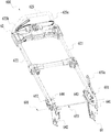
- FIG. 1 is a perspective view of a hand-propelled power tool.
- FIG. 2 is a perspective view of the handle assembly of the hand-propelled power tool connected to the main casing in FIG. 1 .
- FIG. 3 is a perspective view of the handle assembly of the hand-propelled power tool of FIG. 1 .
- FIG. 4 is a partial enlarged view of portion A of the hand-propelled power tool shown in FIG. 3 .
- FIG. 5 is a partial enlarged view of portion B of the hand-propelled power tool shown in FIG. 3 .
- FIG. 6 is a perspective view of another arrangement of a second elastic member of the hand-push power tool illustrated in FIG. 3 .
- FIG. 7 is a schematic view of a partial structure of a hand-propelled power tool according to a second example.
- FIG. 8 is a perspective view of a partial structure of the hand-propelled power tool of FIG. 7 .
- FIG. 9 is a perspective view of a partial structure of the hand-propelled power tool of FIG. 7 observed from another perspective.
- FIG. 10 is a front view of a partial structure of the hand-propelled power tool of FIG. 7 .
- FIG. 11 is a schematic view of a partial structure of a hand-propelled power tool according to a third example, in which the adjusting assembly is in a locked state.
- FIG. 12 is a schematic view of a partial structure of a hand-propelled power tool according to the third example, in which the adjusting assembly is in a released state.
- FIG. 13 is a plan view of a partial structure of a hand-propelled power tool according to the third example.
- FIG. 14 is a schematic view of a partial structure of a hand-propelled power tool according to a fourth example.
- FIG. 15 is a perspective view of a partial structure of the hand-propelled power tool of FIG. 14 .
- FIG. 16 is a schematic view of a partial structure of a hand-propelled power tool according to a fifth example.
- FIG. 17 is a partial structure of the handle devise according to the fifth example.
- FIG. 18 is an enlarged view of a part of the structure shown in FIG. 17 .
- an example of the hand-propelled power tool is a lawnmower 100 .
- the lawnmower 100 includes a main body 11 , a handle assembly 12 , and a walking assembly 13 .
- the walking assembly 13 is connected to the main body 11 and is operative to drive the lawnmower 100 to walk.
- the main body 11 includes a main casing 111 that is used to enclose at least part of the main body 11 .
- the handle assembly 12 is rotatably connected to the main casing 111 and may be rotated to a preset angle to adjust the operating posture or reduce the occupied space to enter a storage state.
- the main body 11 further includes a prime mover and a cutting accessory.
- the cutting accessory can be driven by the prime mover to perform the cutting function.
- the cutting accessory may specifically be a cutting blade
- the prime mover may specifically be a motor
- the main body 11 may be provided with an accommodating space for accommodating the motor.
- the motor drives the cutting blade to rotate at high speeds.
- the handle assembly 12 can be operated by an operator to control the output power, walking path, and walking state of the lawnmower 100 .
- the handle assembly 12 includes a gripping portion 124 for a user to grip, a portion of the gripping portion 124 extending along a first line 100 a , and the gripping portion 124 includes a first end 124 a and a second end 124 b opposite to the first end 124 a .
- the handle assembly 12 includes a connecting rod 121 and an operating portion 122 .
- the connecting rod 121 is connected to the main casing 111 and is rotatable around the main body 11 .
- the operating portion 122 is connected to the connecting rod 121 and is operative to control the lawnmower 100 .
- the connecting rod 121 is rotatably connected to the main body 11 , and is operative to rotate around a first rotational axis 101 so that the user can adjust the connecting rod 121 to an appropriate angle, thereby meeting the needs of users of different heights.
- the connecting rod 121 may include a first connecting rod 121 a and a second connecting rod 121 b .
- the first connecting rod 121 a connects the first end 124 a of the gripping portion 124 and the main body 11
- the second connecting rod 121 b connects the second end 124 b of the gripping portion 124 and the main body 11 .
- the first connecting rod 121 a and the second connecting rod 121 b are each connected to the main body 11 , and are connected as a whole by the first linkage member 151 a and the operating portion 122 . It will be appreciated that, since they are fixed by the first linkage member 151 a and the operating portion 122 , the ends of the first connecting rod 121 a and the second connecting rod 121 b connected to the main body 11 constitute two free ends.
- the first connecting rod 121 a is capable of rotating relative to the main body 11 about a first axis.
- the second connecting rod 121 b is capable of rotating relative to the main body 11 about a axis parallel to the first axis.
- the junctions of the first connecting rod 121 a and the second connecting rod 121 b with the main body 11 may be connected as a whole through a pivot shaft 123 .
- the first rotational axis 101 is located within the pivot shaft 123 .
- the force originally acting on the junction between the first connecting rod 121 a and the main body 11 or the force acting on the junction between the second connecting rod 121 b and the main body 11 can be directly transferred to the pivot shaft 123 .
- the pivot shaft 123 has a larger contact area with the main body 11 , and the stress is more uniform.
- the pivot shaft 123 is also connected to the free ends of the first connecting rod 121 a and the second connecting rod 121 b , so that the first connecting rod 121 a and the second connecting rod 121 b would have a more stable connection with the main body 11 , and so they will not shake when being stressed, which otherwise would affect the user's operation.
- the lawnmower 100 is further provided with a fixing plate assembly 14 for fixing the handle assembly 12 to a preset angle, and an adjusting assembly 15 for locking the handle assembly 12 to a preset position.
- the fixing plate assembly 14 includes a first fixing plate 141 that cooperates with the first connecting rod 121 a and a second fixing plate 142 that cooperates with the second connecting rod 121 b .
- the first fixing plate 141 is fixedly connected to the main body 11 and is basically located between the first connecting rod 121 a and the main body 11 . During the rotation of the first connecting rod 121 a around the first rotational axis 101 , the first connecting rod 121 a actually rotates around the first fixing plate 141 as well.
- the second fixing plate 142 is fixedly connected to the main body 11 and is basically located between the second connecting rod 121 b and the main body 11 .
- the fixing plate assembly 14 is provided with a plurality of locking holes 143 for fixing the connecting rod 121 .
- the locking holes 143 are operative to engage with a locking pin in the adjusting assembly 15 to lock the connecting rod 121 at a preset angle.
- the adjusting assembly 15 may specifically include a first adjusting assembly 151 , a second adjusting assembly 152 , and a transmission assembly 153 connecting the first adjusting assembly 151 with the second adjusting assembly 152 .
- the first adjusting assembly 151 is configured to lock or release the rotation of the first connecting rod 121 a relative to the main body 11 .
- the first adjusting assembly 151 is used to lock or release the connection between the first connecting rod 121 a and the first fixing plate 141 .
- the second adjusting assembly 152 is configured to lock or release the rotation of the second connecting rod 121 a relative to the main body 11 .
- the second adjusting assembly 152 is used to lock or release the connection between the second connecting rod 121 b and the second fixing plate 142 .
- the first adjusting assembly 151 and the second adjusting assembly 152 have a first movement state from the locked state to the released state and a second movement state from the released state to the locked state.
- the transmission assembly 153 can transmit a force between the first adjusting assembly 151 and the second adjusting assembly 152 .
- the transmission assembly 153 does not transmit a force between the first adjusting assembly 151 and the second adjusting assembly 152 .
- the first adjusting assembly 151 is mounted at the first connecting rod 121 a
- the second adjusting assembly 152 is mounted at the second connecting rod 121 b
- the first connecting rod 121 a can be locked to the main body 11 by the first adjusting assembly 151
- the second connecting rod 121 b can be locked to the main body 11 by the second adjusting assembly 152 . So, the handle can be more stably locked to the main body 11 by two adjusting assemblies, thereby preventing the lawnmower 100 from shaking during operation and improving the strength of the lawnmower 100 .
- the lawnmower 100 further includes an operating member 151 c for the user to operate to drive the first adjusting assembly 151 to release the rotation of the first connecting rod 121 a relative to the main body 11 .
- the operating member 151 c is capable of moving to a first position and a second position relative to the handle assembly 12 .
- the operating member 151 c drives the first adjusting assembly 151 to release the rotation of the first connecting rod 121 a relative to the main body 11
- the transmission assembly 153 drives the second adjusting assembly 152 to release the rotation of the second connecting rod 121 b relative to the main body 11 .
- the user only needs to operate the operating member 151 c , that is, the first adjusting assembly 151 can release the rotation of the first connecting rod 121 a at the same time, and the second adjusting assembly 152 can also release the rotation of the second connecting rod 121 b , thereby facilitating the operation of the user.
- the transmission assembly 153 transmits a force between the first adjusting assembly 151 and the second adjusting assembly 152 , so the transmission assembly 153 transmits a motion between the first adjusting assembly 151 and the second adjusting assembly 152 .
- the transmission assembly 151 does not transmit a force between the first adjusting assembly 151 and the second adjusting assembly 152 , so the transmission assembly 153 does not transmit motion between the first adjusting assembly 151 and the second adjusting assembly 152 .
- the transmission assembly 153 transmits a motion from the first adjusting assembly 151 to the second adjusting assembly 152 .
- the transmission assembly 153 does not transmit a motion from the first adjusting assembly 151 to the second adjusting assembly 152 .
- the first adjusting assembly 151 may include a first linkage member 151 a , a first locking member, and a first elastic member 151 d , and the first locking member is a first locking pin 151 b .
- the first linkage member 151 a connects the first locking pin 151 b and the transmission assembly 153 .
- the first linkage member 151 a is substantially distributed along an extending direction of the first connecting rod 121 a .
- the first linkage member 151 a is rotatably connected to the first connecting rod 121 a around a second rotational shaft 102 and is located on the side of the first connecting rod 121 a facing away from the second connecting rod 121 b .
- the operating member 151 c is connected to the first linkage member 151 a , and is operable to control the first linkage member 151 a to rotate around the second rotational shaft 102 .
- the first locking pin 151 b connects the first connecting rod 121 a and the main body 11 to lock the rotation of the first connecting rod 121 a .
- the first locking pin 151 b is disposed on the first linkage member 151 a and is located on the side of the second rotational shaft 102 away from the operating member 151 c .
- the first connecting rod 121 a is also provided with a first through hole through which the first locking pin 151 b is can pass. The first through hole can be aligned with the locking hole 143 in the fixing plate assembly 14 , then the first locking pin 151 b inserts the first locking hole 143 so that the handle assembly 12 can be locked to a preset angle by the first locking pin 151 b .
- the first adjusting assembly 151 actually forms a lever structure with the second rotational shaft 102 as a fulcrum.
- the first locking pin 151 b can be controlled to enter or disengage from the locking hole 143 , so that the handle assembly 12 can be locked or released.
- the first elastic member 151 d is configured to drive first locking pin 151 b to reset to lock the rotation of the first connecting rod 121 a .
- a first elastic member 151 d may be further provided between the first linkage member 151 a and the first connecting rod 121 a , where the first elastic member 151 d may specifically be a coil spring. More specifically, the first elastic member 151 d may be located between the second rotating shaft 102 and the operating member 151 c .
- the first locking pin 151 b can be disengaged from the locking hole 143 under the lever action, thereby releasing the handle assembly 12 .
- the first elastic member 151 d is reset and is operative to push the first linkage member 151 a to reset in the second direction.
- the first locking pin 151 b can enter the locking hole 143 under the lever action, thus locking the handle assembly 12 .
- the first elastic member 151 d biases the operating member 151 c to move to the first position. So the operating member 151 c can release to the first position when the user does not operate the operating member 151 c .
- the second adjusting assembly 152 includes a second linkage member 152 a , a second locking member, and a second elastic member 152 c , and the second locking member is a second locking pin 152 b .
- the second linkage member 152 a is substantially distributed along an extending direction of the second connecting rod 121 b .
- the second linkage member 152 a is rotatably connected to the second connecting rod 121 b around a third rotational shaft 103 and is located on the side of the second connecting rod 121 b away from the first connecting rod 121 a .
- the second linkage member 152 a connects the second locking pin 152 b and the transmission assembly 153 .
- the second locking pin 152 b configured to connect the second connecting rod 121 b and the main body 11 to lock the rotation of the second connecting rod 121 b .
- the second locking pin 152 b is arranged on the second linkage member 152 a , and a second through hole through which the second locking pin 152 b can pass is also provided in the second connecting rod 121 b .
- the second through hole can be aligned with the locking hole 143 in the second fixing plate 142 , then the second locking pin 152 b inserts the locking hole so that the handle assembly 12 can be locked to a preset angle by the second locking pin 152 b .
- the pivot shaft 123 may be provided with a through-hole through which the transmission assembly 153 can pass.
- the transmission assembly 153 is disposed in the pivot shaft 123 , where one end of the transmission assembly 153 is connected to the first linkage member 151 a , and the other end is connected to the second linkage member 152 a .
- the first linkage member 151 a rotates in the first direction around the second axis.
- the operating member 151 c is disposed on a side of the second axis, and the first locking pin 151 b and the transmission assembly 153 are dispose on another side of the second axis.
- the transmission assembly 153 located between the first linkage member 151 a and the second linkage member 152 a can drive the second linkage member 152 a to rotate around the third rotational shaft 103 .
- the operating handle may also be arranged on the second linkage member 152 a , and when the second linkage member 152 a is operated to rotate, the first linkage member 151 a may also be driven to rotate synchronously by means of the transmission assembly 153 .
- first linkage member 151 a and the second linkage member 152 a have a linkage relationship through the transmission assembly 153 , but the first linkage member 151 a and the second linkage member 152 a are not rigidly connected; that is, the first linkage member 151 a and the second linkage member 152 a can have relative displacement.
- the transmission assembly 153 may be made of a non-rigid material, which may specifically be a steel wire rope, nylon rope, etc., which is capable of transmitting a tensile force, but is unable to transmit a stress or may transmit less stress.
- first locking pin 151 b provided on the first linkage member 151 a and the second locking pin 152 b provided on the second linkage member 152 a need to enter the locking holes 143 on the fixing plate assembly 14 at the same time, which requires the first through hole and the second through hole be simultaneously aligned with the locking holes 143 on the fixing plate assembly 14 .
- the first through hole and the second through hole cannot be aligned with the locking holes 143 in the fixing plate assembly 14 at the same time, such that the first locking pin 151 b on the first linkage member 151 a and the second locking pin 152 b on the second linkage member 152 a cannot enter the corresponding locking hole 143 , or they cannot enter the locking holes 143 synchronously. As a result, the handle assembly 12 cannot be locked.
- the first linkage member 151 a and second linkage member 152 a that are non-rigidly connected, even if the first through hole and the second through hole are not aligned with the locking holes 143 in the fixing plate assembly 14 at the same time, the first locking pin 151 b provided on the first linkage member 151 a or the second locking pin 152 b arranged on the second linkage member 152 a can still enter the locking hole 143 , and after one of the locking pins enters the corresponding locking hole 143 , the other connecting rod can be shaken so that the other locking pin can also enter the corresponding locking hole 143 .
- the other locking pin will not be prevented from entering the corresponding locking hole 143 due to the linkage relationship between the first linkage member 151 a and the second linkage member 152 a . That is, by providing the non-rigid connection between the first linkage member 151 a and the second linkage member 152 a , the first locking pin 151 b and the second locking pin 152 b arranged on the first linkage member 151 a and the second linkage member 152 a can both enter their respective locking holes 143 , thereby ensuring the reliability of the handle assembly 12 entering the locked state from the released state.
- the second adjusting assembly 152 actually forms a lever structure with the third rotational shaft 103 as a fulcrum.
- the transmission assembly 153 drives the second linkage member 152 a to rotate in the first direction
- the second linkage member 152 a can drive the second locking pin 152 b to disengage from the corresponding locking hole 143 , thereby releasing the handle assembly 12 .
- a second elastic member 152 c may be further arranged between the second linkage member 152 a and the second connecting rod 121 b .
- the second elastic member 152 c is configured to drive second locking pin 152 b to reset to lock the rotation of the second connecting rod 121 b .
- the second elastic member 152 c is disposed between the third rotating shaft 103 and the transmission assembly 153 .
- the transmission assembly 153 drives the second linkage member 152 a to rotate in the first direction
- the second elastic member 152 c is compressed.
- the operating member 151 c is released, the first elastic member 151 d is reset so that the first linkage member 151 a rotates in the second direction.
- the second elastic member 152 c is also reset, making the second linkage member 152 a rotate in the second direction under the leverage, so that the second locking pin 152 b provided on the second linkage member 152 a enters the locking hole 143 in the second fixing plate 142 , thereby locking the handle assembly 12 .
- first linkage member 151 a and the second linkage member 152 a are connected by a non-rigid connection through the transmission assembly 153 , the first linkage member 151 a and the second linkage member 152 a can be reset under the actions of the first elastic member 151 d and the second elastic member 152 c , and the first linkage member 151 a and the second linkage member 152 a will not interfere with each other.
- the first locking pin 151 b and the second locking pin 152 b can lock the first linkage member 151 a and the second linkage member 152 a , separately.
- the second elastic member 152 c may also be directly disposed on the end of the second locking pin 152 b on the second linkage member 152 a away from the first linkage member 151 a .
- the transmission assembly 153 drives the second linkage member 152 a to rotate in the first direction
- the second elastic member 152 c is compressed.
- the first elastic member 151 d is reset so that the first linkage member 151 a in the second direction.
- the second elastic member 152 c is also reset, directly driving the second linkage member 152 a to rotate in the second direction, so that the second locking pin 152 b provided on the second linkage member 152 a enters the locking hole 143 in the second fixing plate 142 , thereby locking the handle assembly 12 .
- the operating member 151 c may be operated to make the first linkage member 151 a rotate around the second rotational shaft 102 in the first direction, and at this time, the first elastic member 151 d is compressed so that the first locking pin 151 b on the first linkage member 151 a is disengaged from the corresponding locking hole 143 in the fixing plate 141 .
- the transmission assembly 153 connected between the first linkage member 151 a and the second linkage member 152 a drives the second linkage member 152 a to rotate about the third rotational shaft 103 in the first direction.
- the handle assembly 12 is released and can freely rotate around the first rotational axis 101 .
- the operator may release the operating member 151 c , at which time the first linkage member 151 a is reset under the action of the first elastic member 151 d , and the second linkage member 152 a is also reset under the action of the second elastic member 152 c .
- the first locking pin 151 b provided on the first linkage member 151 a can be driven by the first linkage member 151 a to enter the locking hole 143 in the first fixing plate 141 , and the second locking pin 152 b provided on the second linkage member 152 a can be driven into the locking hole 143 in the second fixing plate 142 by the second linkage member 152 a , thereby realizing the locking purpose.
- the hand-propelled power tool according to the second example also includes a handle device 22 and a main body 21 , where FIG. 7 only shows a partial structure of the handle device 22 and the main body 21 .
- the hand-propelled power tool according to this example differs from that according to the first example in that the structure of the adjusting assembly 222 of the handle device 22 and the principle of adjusting the position of the handle device 22 relative to the main body 21 are different, while the same features as those in the first example can all be applied to this example.
- the operating assembly 224 is configured for being operated by the user.
- the connecting member and the main body 21 form a slidable connection along the second straight line 201 , where the second straight line 201 is substantially perpendicular to a first axis 201 a .
- the connecting member may specifically be a bolt.
- the main body 21 is provided with a matching portion 211 a that collaborates with the connecting member, where the matching portion 211 a may specifically be a hole that fits with the bolt to form a shaft-hole-fitting.
- the operating assembly 224 includes a handle used to be operated by the user.
- the adjusting assembly is movably connected to the elongated rod body 221 , and is operative to rotate relative to the elongated rod body 221 with the first axis 201 a as the rotational axis.
- the connecting member forms a fixed connection or a linkage with the operating assembly 224 along the second straight line 201 .
- the adjusting assembly 8 may be applied to the operating assembly 224 , and so the adjusting assembly rotates counterclockwise about the second axis, thereby driving the connecting member to be disengaged from the matching portion 211 a , so that the adjusting assembly is switched to the released state, where the second axis is perpendicular to the plane in which the elongated rod body 221 lies.
- the elongated rod body 221 has a bisecting plane A.
- the elongated rod body 221 is substantially symmetrical about the bisecting plane A and includes a first connecting rod and a second connecting rod.
- At least two connecting members 222 a are respectively disposed on both sides of the bisecting plane A and form a linkage with each other.
- a first adjusting assembly 222 is provided on one side of the first connecting rod, and includes a first connecting member 222 a .
- a second adjusting assembly 223 is provided on one side of the second connecting rod, and includes a second connecting member 223 a .
- the second connecting member 223 a may also be an insertion bolt.
- the second connecting member 223 a and the first adjusting assembly 222 form a linkage.
- the second connecting member 223 a may form a linkage with the first adjusting assembly 222 through the transmission assembly 225 .
- the transmission assembly 225 includes a rope extending in a direction parallel to the second straight line 201 .
- the second adjusting assembly 223 may rotate about the third axis in the counterclockwise direction under the drive of the rope, thereby causing the second connecting member 223 a to be disengaged from the matching portion 211 a , and so the second adjusting assembly 223 is switched to the released state, where the third axis is parallel to the second axis.
- the first adjusting assembly 222 and the second adjusting assembly 223 include a first elastic member 222 b and a second elastic member 223 b , respectively.
- the first elastic member 222 b and the second elastic member 223 b may be elastically deformed in a direction parallel to the second straight line 201 .
- the first connecting member 222 a and the second connecting member 223 a may rebound to their original positions under the action of the elastic forces of the first elastic member 222 b and the second elastic member 223 b , and so the first adjusting assembly 222 and the second adjusting assembly 223 are switched to the locked state.
- the first elastic member 222 b and the second elastic member 223 b are typically compression springs.
- the rope of the transmission assembly 225 typically has a metal rope or brake wire with certain strength.
- the operating assembly 224 is disposed on the upper end of the first adjusting assembly 222 .
- the rope passes through the first connecting rod and connects the lower end of the first adjusting assembly 222 to the lower end of the second adjusting assembly 223 .
- FIGS. 11 to 13 show a partial structure of a handle device 32 and a main body of a hand-propelled power tool according to the third example.
- the principle of adjusting the position of the handle device 32 relative to the main body in this example is basically the same as that in the second example. The difference lies in the specific structure of the adjusting assembly. The similarities between this example and the second example can all be applied to this example.
- a first adjusting assembly 322 and a second adjusting assembly 323 are arranged on both sides of the bisecting plane of the elongated rod body 321 , respectively.
- the first adjusting assembly 322 and the second adjusting assembly 323 are connected by a rope and are substantially symmetrical about the bisecting plane.
- the first adjusting assembly 322 includes a first locking pin 322 a and a first elastic member 322 b having the same functions as those in the first example.
- the second adjusting assembly 323 includes a second locking pin 323 a and a second elastic member 323 b having the same functions as those in the first example.
- the first locking pin 322 a and the second locking pin 323 a each form a slidable connection with the elongated rod body 321 along the second straight line 201 . Both the first locking pin 322 a and the second locking pin 323 a are insertion bolts.
- the handle device 32 also includes an operating member 324 used for being operated.
- the hand-propelled power tool further comprises a first transmission assembly 32 a and a second transmission assembly 32 b .
- the first transmission assembly 32 a is used to transmit a power between the operating member 324 and the first adjusting assembly 323
- the second transmission assembly 32 b is used to transmit a power between the operating member 324 and the second adjusting assembly 322 .
- the main body includes a first plate and a second plate having the same functions as those in the first example.
- the operating member 324 is connected to the rope, and by operating the operating member 324 the effective length (straight line length) of the rope between the first adjusting assembly 322 and the second adjusting assembly 323 can be changed.
- the rope passes through the operating member 324 , and a rotational force F 2 may be applied to the operating member 324 to make the operating member 324 rotate about the third axis 301 a thus changing the effective length of the rope between the first adjusting assembly 322 and the second adjusting assembly 323 , so that the first adjusting assembly 322 and the second adjusting assembly 323 are switched from the locked state illustrated in FIG. 11 to the released state illustrated in FIG. 12 under the driving of the rope.
- a rotational force F 2 may be applied to the operating member 324 to make the operating member 324 rotate about the third axis 301 a thus changing the effective length of the rope between the first adjusting assembly 322 and the second adjusting assembly 323 , so that the first adjusting assembly 322 and the second adjusting assembly 323 are switched from the locked state illustrated in FIG. 11 to the released state illustrated in FIG. 12 under the driving of the rope.
- the first locking pin 322 a and the second locking pin 323 a may rebound to their original positions under the elastic forces of the first elastic member 322 b and the second elastic member 323 b , respectively, so that the first adjusting assembly 322 and the second adjusting assembly 323 are switched from the released state illustrated in FIG. 12 to the locked state illustrated in FIG. 11 , while the operating member 324 rotates back to its original position, and the rope is restored to its original effective length.
- FIGS. 14 and 15 are schematic diagrams illustrating a partial structure of a handle device 42 and a main body according to the fourth example.
- the principle of adjusting the position of the handle device 42 relative to the main body in this example is basically the same as that in the first example. The difference lies in the specific structure of the adjusting assembly. The similarities between this example and the first example can all be applied to this example.
- a first adjusting assembly 422 and a second adjusting assembly 423 are arranged on both sides of the bisecting plane of the elongated rod body 421 , respectively.
- the first adjusting assembly 422 and the second adjusting assembly 423 are connected by a rope and are substantially symmetrical about the bisecting plane.
- the first adjusting assembly 422 includes a first connecting member 422 a and a first elastic member 422 b having the same functions as those in the second example.
- the second adjusting assembly 423 includes a second connecting member 423 a and a second elastic member 423 b having the same functions as those in the second example.
- the first connecting member 422 a and the second connecting member 423 a each form a slidable connection with the elongated rod body 421 along a first straight line 401 .
- Both the first connecting member 422 a and the second connecting member 423 a are insertion bolts.
- the handle device 42 further includes an operating assembly 424 used for being operated by the user.
- the operating assembly 424 is connected to a rope, and can be operated in order to drive the first connecting member 422 a and the second connecting member 423 a to move relative to the main body in the first straight line 401 .
- first connecting member 422 a and the second connecting member 423 a each form a shaft-hole-fitting with the matching portion on the main body, the first connecting member 422 a and the second connecting member 423 a may perform a sliding motion relative to the main body in the first straight line 401 .
- the operating assembly 424 is disposed above the adjusting assembly. Typically, the operating assembly 424 is disposed above at least a part of the elongated rod body 421 to facilitate user operation.
- One end of the operating assembly 424 is connected to the first connecting member 422 a through a first rope 425 a , which extends in the first straight line 401 .
- the other end of the operating assembly 424 is connected to the second connecting member 423 a through a second rope 425 b . At least a portion of the second rope 425 b extends in the first straight line 401 .
- the second rope 425 b changes its extending direction by connecting to a fixed pulley, so that the extending direction of the other part of the rope is substantially parallel to the second straight line 201 .
- a handle housing 426 for mounting the operating assembly 424 and the fixed pulley is provided between the elongated rod body 421 .
- the operating assembly 424 forms a rotatable connection relative to the handle housing 426 .
- both the first adjusting assembly 422 and the second adjusting assembly 423 are in a locked state.
- a driving force F 3 in the direction indicated by the arrow is applied to the operating assembly 424 , the operating assembly 424 would rotate relative to the handle housing 426 in the counterclockwise direction, and the first connecting member 422 a and the second connecting member 423 a would move in the direction indicated by the arrow under the pulling of the first rope 425 a and the second rope 425 b , respectively, so that the first adjusting assembly 422 and the second adjusting assembly 423 would switch from the locked state to the released state.
- the first elastic member 422 b and the second elastic member 423 b are mounted to the first connecting member 422 a and the second connecting member 423 a , respectively.
- the first connecting member 422 a moves upward as indicated by the arrow, the first elastic member 422 b is stretched.
- the driving force F 3 is released, the first connecting member 422 a rebounds to its original position under the elastic force of the first elastic member 422 b .
- the second connecting member 423 a moves upward as indicated by the arrow, the second elastic member 423 b is stretched.
- the operating assembly 424 is released, the second connecting member 423 a rebounds to its original position under the elastic force of the second elastic member 423 b , thus making the first adjusting assembly 422 switch from the released state to the locked state.
- FIG. 16 shows a partial structure of a hand-propelled power tool 600 of a fifth example.
- the hand-propelled power tool 600 is a lawnmower.
- the hand-propelled power tool 600 includes a handle device and a main body 61 , and the main body 61 has substantially the same structure as the main body 11 in the first example.
- the handle device includes a handle assembly 62 , and the handle assembly 62 includes a gripping portion 623 , a first connecting rod 621 , and a second connecting rod 622 .
- the gripping portion 623 is used for the gripping portion 623 held by the user.
- the gripping portion 623 includes opposite ends, and the opposite ends are a first end 623 a and a second end 623 b .
- the first connecting rod 621 connects the first end 623 a of the gripping portion 623 and the main body 61
- the second connecting rod 622 connects the second end 623 b of the gripping portion 623 and the main body 61 .
- the handle device can rotate relative to the main body 61 about a first rotational axis 601 .
- the handle device can rotate relative to the main body 61 about the first rotational axis 601 to a folded position and an operating position.
- the handle device can be in a plurality of different operating positions relative to the main body 61 , so that users with different heights can comfortably operate the hand-propelled power tool 600 .
- the handle device further includes a first adjusting assembly 651 and a second adjusting assembly 652 , the first adjusting assembly 651 is used to lock or release the rotation of the first connecting rod 621 relative to the main body 61 , and the second adjusting assembly 652 is used to lock or release the rotation of the second connecting rod 622 relative to the main body 61 .
- the first adjusting assembly 651 is mounted to the first connecting rod 621
- the second adjusting assembly 652 is mounted to the second connecting rod 622 .
- the first adjusting assembly 651 is disposed on the left side of the hand-propelled power tool 600
- the second adjusting assembly 652 is disposed on the right side of the hand-propelled power tool 600 .
- the rotation of the first connecting rod 621 and the second connecting rod 622 relative to the main body 61 is locked by the first adjusting assembly 651 and the second adjusting assembly 652 respectively, so that the structure of the hand-propelled power tool 600 is more stable, the shaking of the handle device relative to the main body 61 is small, and the structural strength of the hand-propelled power tool 600 is improved.
- the handle device further includes an operating member 651 c and a transmission assembly 653 .
- the operating member 651 c can move to a first position and a second position relative to the first connecting rod 621 .
- the operating member 651 c drives the first adjusting assembly 651 to release the rotation of the first connecting rod 621 with respect to the main body 61 , and the first connecting rod 621 can rotate relative to the main body 61 at this time.
- the transmission assembly 653 is used to connect the first adjusting assembly 651 and the second adjusting assembly 652 .
- the transmission assembly 653 transmits the movement of the first adjusting assembly 651 to the second adjusting assembly 652 and drives the second adjusting assembly 652 moves, and the second adjusting assembly 652 releases the rotation of the second connecting rod 622 relative to the main body 61 under the driving of the transmission assembly 653 .
- the user only needs one hand to operate the operating member 651 c , so that the first adjusting assembly 651 can release the rotation of the first connecting rod 621 relative to the main body 61 , and can also cause the second adjusting assembly 652 to release the rotation of the second connecting rod 622 relative to the main body, which makes user operation more convenient and faster.
- the transmission assembly 653 transmits a force between the first adjusting assembly 651 and the second adjusting assembly 652 .
- the first adjusting assembly 651 releases the rotation of the first connecting rod 621 relative to the main body 61
- the second adjusting assembly 652 can also release the rotation of the first connecting rod 621 relative to the main body 61 .
- the transmission assembly 653 cannot transmit a force between the first adjusting assembly 651 and the second adjusting assembly 652 .
- the first adjusting assembly 651 no longer restricts the movement of the second adjusting assembly 652 .
- the movement of a second locking pin 652 b of the second adjusting assembly 652 will not be restricted by the first adjusting assembly 651 , so that the second locking pin 652 b can automatically align with a second locking hole 644 under the action of a second elastic member 652 c and inserted into the second locking hole 644 , thereby avoiding the problem that the second locking pin 652 b is restricted by the first adjusting assembly 651 and cannot be aligned with the second locking hole 644 when resetting.
- the operating member 651 c may be regarded as a part of the first adjusting assembly 651 , or a part of the operating member 651 c may be regarded as a part of the first adjusting assembly 651 .
- the transmission assembly 653 includes a connecting member 653 a and a limiting member 653 b .
- the connecting member 653 a connects the first adjusting assembly 651 and the second adjusting assembly 652 .
- the connecting member 653 a is a rigid connecting rod, and the rigid connecting rod extends along the first rotational axis 601 .
- One end of the connecting member 653 a is connected to the operating member 651 c , and the operating member 651 c is rotatably connected to the connecting member 653 a .
- the operating member 651 c is also rotatably connected to the first connecting rod 621 .
- the operating member 651 c When the operating member 651 c rotates relative to the first connecting rod 621 , it can drive the connecting member 653 a to slide along the direction of the first rotational axis 601 .
- the other end of the connecting member 653 a is connected to a second linkage member 652 a of the second adjusting assembly 652 , and a hole 652 e is formed in the second linkage member 652 a .
- the connecting member 653 a passes through the hole 652 e and can be opposite to slide relative to the second linkage member 652 a along the first rotational axis 60 .
- the limiting member 653 b is mounted on the connecting member 653 a , and is located on the side of the second linkage member 652 a away from the first adjusting assembly 651 . In this way, when the connecting member 653 a slides along the first rotational axis 601 toward the first adjusting assembly 651 , the limiting member 653 b pushes the second linkage member 652 a to move with the connecting member 653 a , so that the second linkage member 652 a can rotate relative to the second connecting rod 622 and the second locking pin 652 b is disengaged from the second fixing plate 642 .
- the connecting member 653 a slides along the first rotational axis 601 toward the second adjusting assembly 652 , the limiting member 653 b no longer limits the second linkage member 652 a , and the connecting member 653 a no longer drives the second linkage member 652 a to move.
- the second linkage member 652 a is reset by the second elastic member 652 c . That is to say, when the operating member 651 c moves from the first position to the second position, the transmission assembly 653 transmits motion between the first adjusting assembly 651 and the second adjusting assembly 652 . When the operating member 651 c is moved from the second position to the first position, the transmission assembly 653 does not transmit motion between the first adjusting assembly 651 and the second adjusting assembly 652 .
Landscapes
- Engineering & Computer Science (AREA)
- Life Sciences & Earth Sciences (AREA)
- Environmental Sciences (AREA)
- Mechanical Engineering (AREA)
- Chemical & Material Sciences (AREA)
- Combustion & Propulsion (AREA)
- Transportation (AREA)
- Architecture (AREA)
- Civil Engineering (AREA)
- Structural Engineering (AREA)
- Harvester Elements (AREA)
Abstract
Description
Claims (19)
Applications Claiming Priority (4)
| Application Number | Priority Date | Filing Date | Title |
|---|---|---|---|
| CN201910641003.6 | 2019-07-16 | ||
| CN201910641003 | 2019-07-16 | ||
| CN202010268480.5A CN112237085B (en) | 2019-07-16 | 2020-04-08 | Hand-push type power tool |
| CN202010268480.5 | 2020-04-08 |
Publications (2)
| Publication Number | Publication Date |
|---|---|
| US20210016817A1 US20210016817A1 (en) | 2021-01-21 |
| US11219161B2 true US11219161B2 (en) | 2022-01-11 |
Family
ID=71522993
Family Applications (1)
| Application Number | Title | Priority Date | Filing Date |
|---|---|---|---|
| US16/922,118 Active US11219161B2 (en) | 2019-07-16 | 2020-07-07 | Hand-propelled power tool |
Country Status (2)
| Country | Link |
|---|---|
| US (1) | US11219161B2 (en) |
| EP (1) | EP3766328B1 (en) |
Cited By (1)
| Publication number | Priority date | Publication date | Assignee | Title |
|---|---|---|---|---|
| US20210153427A1 (en) * | 2019-11-21 | 2021-05-27 | Globe (Jiangsu) Co., Ltd | Garden tool and control method thereof |
Families Citing this family (4)
| Publication number | Priority date | Publication date | Assignee | Title |
|---|---|---|---|---|
| US10595460B1 (en) * | 2016-08-29 | 2020-03-24 | Briggs & Stratton Corporation | Power rake devices |
| CN106818024A (en) * | 2017-01-03 | 2017-06-13 | 天佑电器(苏州)有限公司 | Garden instrument transfer bar mechanism and the garden instrument with the mechanism |
| US12329063B2 (en) * | 2021-02-12 | 2025-06-17 | Techtronic Cordless Gp | Handle assembly for a power tool |
| US11937544B2 (en) * | 2021-03-02 | 2024-03-26 | Honda Motor Co., Ltd. | Electric mower switch system |
Citations (8)
| Publication number | Priority date | Publication date | Assignee | Title |
|---|---|---|---|---|
| EP1752036A1 (en) * | 2005-08-09 | 2007-02-14 | Outils Wolf | Handguided soil working device, in particular lawn mower |
| DE202007008802U1 (en) * | 2007-06-23 | 2007-10-11 | Expresso Deutschland Gmbh | Adjusting handle mechanism for trolleys, stacking carts and the like. |
| CN102523817A (en) * | 2012-02-22 | 2012-07-04 | 南京德朔实业有限公司 | Multi-gear handle mechanism and lawn mower comprising same |
| US20130111866A1 (en) | 2011-11-03 | 2013-05-09 | Briggs & Stratton Corporation | Vertically storable engine and mower |
| EP2684439A1 (en) | 2012-07-12 | 2014-01-15 | GGP Italy S.p.A. | Machine for mowing lawns and gardens with an adjustable articulated frame |
| US20150101301A1 (en) * | 2013-10-10 | 2015-04-16 | Chervon Intellectual Property Limited | Gardening tool, particularly mower |
| CN205546535U (en) * | 2016-03-23 | 2016-09-07 | 南京德朔实业有限公司 | power tool |
| CN206525151U (en) * | 2017-02-28 | 2017-09-29 | 江苏东郁园林科技有限公司 | Hay mover |
-
2020
- 2020-07-07 US US16/922,118 patent/US11219161B2/en active Active
- 2020-07-07 EP EP20184355.4A patent/EP3766328B1/en active Active
Patent Citations (9)
| Publication number | Priority date | Publication date | Assignee | Title |
|---|---|---|---|---|
| EP1752036A1 (en) * | 2005-08-09 | 2007-02-14 | Outils Wolf | Handguided soil working device, in particular lawn mower |
| DE202007008802U1 (en) * | 2007-06-23 | 2007-10-11 | Expresso Deutschland Gmbh | Adjusting handle mechanism for trolleys, stacking carts and the like. |
| US20130111866A1 (en) | 2011-11-03 | 2013-05-09 | Briggs & Stratton Corporation | Vertically storable engine and mower |
| CN102523817A (en) * | 2012-02-22 | 2012-07-04 | 南京德朔实业有限公司 | Multi-gear handle mechanism and lawn mower comprising same |
| EP2684439A1 (en) | 2012-07-12 | 2014-01-15 | GGP Italy S.p.A. | Machine for mowing lawns and gardens with an adjustable articulated frame |
| US20150101301A1 (en) * | 2013-10-10 | 2015-04-16 | Chervon Intellectual Property Limited | Gardening tool, particularly mower |
| CN205546535U (en) * | 2016-03-23 | 2016-09-07 | 南京德朔实业有限公司 | power tool |
| DE202017100776U1 (en) * | 2016-03-23 | 2017-02-24 | Chervon (Hk) Limited | power tool |
| CN206525151U (en) * | 2017-02-28 | 2017-09-29 | 江苏东郁园林科技有限公司 | Hay mover |
Cited By (2)
| Publication number | Priority date | Publication date | Assignee | Title |
|---|---|---|---|---|
| US20210153427A1 (en) * | 2019-11-21 | 2021-05-27 | Globe (Jiangsu) Co., Ltd | Garden tool and control method thereof |
| US11558999B2 (en) * | 2019-11-21 | 2023-01-24 | Globe (Jiangsu) Co., Ltd | Garden tool and control method thereof |
Also Published As
| Publication number | Publication date |
|---|---|
| EP3766328A1 (en) | 2021-01-20 |
| EP3766328B1 (en) | 2023-04-12 |
| US20210016817A1 (en) | 2021-01-21 |
Similar Documents
| Publication | Publication Date | Title |
|---|---|---|
| US11219161B2 (en) | Hand-propelled power tool | |
| TWI225770B (en) | Walk-behind, self-propelled working machine | |
| CA2802259C (en) | Locking pliers with handle locking mechanism | |
| US9844857B2 (en) | Locking pliers with handle locking mechanism | |
| US8925293B2 (en) | Adjustable handle for outdoor power equipment | |
| EP0444909A2 (en) | Hand-held power tool with a rotary driven tool | |
| CN112237086B (en) | Hand-push type power tool | |
| EP3282826B1 (en) | Lawn mower cutting height adjustment assembly | |
| US5145044A (en) | Two-handle arrangement for a handheld portable tool | |
| NZ528430A (en) | Operator prescence control via a bale coupled to a handle and control arm, typically for electric reel mower | |
| CN212278926U (en) | Cutting height adjustment mechanism for lawn mowers | |
| US5002519A (en) | Dual tension clutch | |
| US5709030A (en) | Garden shear control mechanism | |
| CN101570027B (en) | Electric tool brake apparatus | |
| US3401455A (en) | Portable pruning equipment | |
| CN210053950U (en) | Driving device of hedge trimmer and hedge trimmer | |
| US20230068249A1 (en) | Fastener driving tool | |
| CN115250724A (en) | Working machine | |
| CN101758518B (en) | Power Tool Braking Device | |
| CN113519276B (en) | Cutting height adjustment mechanism of lawn mower | |
| CN116265635B (en) | Sewing machine drive clutch device | |
| US20250237027A1 (en) | Snow remover and attachment | |
| US20250380638A1 (en) | Lid to cover battery housing of power equipment | |
| CN211792787U (en) | Handle assembly and garden tool having the same | |
| JPS5817157Y2 (en) | Belt tension clutch in mobile agricultural machinery |
Legal Events
| Date | Code | Title | Description |
|---|---|---|---|
| AS | Assignment |
Owner name: NANJING CHERVON INDUSTRY CO., LTD., CHINA Free format text: ASSIGNMENT OF ASSIGNORS INTEREST;ASSIGNORS:ZHU, GUANGQIAN;GUO, NA;YAMAOKA, TOSHINARI;AND OTHERS;REEL/FRAME:053135/0821 Effective date: 20200701 |
|
| FEPP | Fee payment procedure |
Free format text: ENTITY STATUS SET TO UNDISCOUNTED (ORIGINAL EVENT CODE: BIG.); ENTITY STATUS OF PATENT OWNER: LARGE ENTITY |
|
| STPP | Information on status: patent application and granting procedure in general |
Free format text: DOCKETED NEW CASE - READY FOR EXAMINATION |
|
| STPP | Information on status: patent application and granting procedure in general |
Free format text: NON FINAL ACTION MAILED |
|
| STPP | Information on status: patent application and granting procedure in general |
Free format text: RESPONSE TO NON-FINAL OFFICE ACTION ENTERED AND FORWARDED TO EXAMINER |
|
| STPP | Information on status: patent application and granting procedure in general |
Free format text: NOTICE OF ALLOWANCE MAILED -- APPLICATION RECEIVED IN OFFICE OF PUBLICATIONS |
|
| STPP | Information on status: patent application and granting procedure in general |
Free format text: PUBLICATIONS -- ISSUE FEE PAYMENT VERIFIED |
|
| STCF | Information on status: patent grant |
Free format text: PATENTED CASE |
|
| MAFP | Maintenance fee payment |
Free format text: PAYMENT OF MAINTENANCE FEE, 4TH YEAR, LARGE ENTITY (ORIGINAL EVENT CODE: M1551); ENTITY STATUS OF PATENT OWNER: LARGE ENTITY Year of fee payment: 4 |