US11218883B2 - User terminal, radio base station, radio communication method and radio communication system - Google Patents
User terminal, radio base station, radio communication method and radio communication system Download PDFInfo
- Publication number
- US11218883B2 US11218883B2 US16/244,969 US201916244969A US11218883B2 US 11218883 B2 US11218883 B2 US 11218883B2 US 201916244969 A US201916244969 A US 201916244969A US 11218883 B2 US11218883 B2 US 11218883B2
- Authority
- US
- United States
- Prior art keywords
- sensing
- user terminal
- subframe
- period
- lbt
- Prior art date
- Legal status (The legal status is an assumption and is not a legal conclusion. Google has not performed a legal analysis and makes no representation as to the accuracy of the status listed.)
- Active
Links
Images


Classifications
-
- H—ELECTRICITY
- H04—ELECTRIC COMMUNICATION TECHNIQUE
- H04W—WIRELESS COMMUNICATION NETWORKS
- H04W16/00—Network planning, e.g. coverage or traffic planning tools; Network deployment, e.g. resource partitioning or cells structures
- H04W16/14—Spectrum sharing arrangements between different networks
-
- H—ELECTRICITY
- H04—ELECTRIC COMMUNICATION TECHNIQUE
- H04L—TRANSMISSION OF DIGITAL INFORMATION, e.g. TELEGRAPHIC COMMUNICATION
- H04L27/00—Modulated-carrier systems
- H04L27/0006—Assessment of spectral gaps suitable for allocating digitally modulated signals, e.g. for carrier allocation in cognitive radio
-
- H—ELECTRICITY
- H04—ELECTRIC COMMUNICATION TECHNIQUE
- H04L—TRANSMISSION OF DIGITAL INFORMATION, e.g. TELEGRAPHIC COMMUNICATION
- H04L5/00—Arrangements affording multiple use of the transmission path
- H04L5/0001—Arrangements for dividing the transmission path
- H04L5/0003—Two-dimensional division
- H04L5/0005—Time-frequency
- H04L5/0007—Time-frequency the frequencies being orthogonal, e.g. OFDM(A) or DMT
- H04L5/001—Time-frequency the frequencies being orthogonal, e.g. OFDM(A) or DMT the frequencies being arranged in component carriers
-
- H—ELECTRICITY
- H04—ELECTRIC COMMUNICATION TECHNIQUE
- H04L—TRANSMISSION OF DIGITAL INFORMATION, e.g. TELEGRAPHIC COMMUNICATION
- H04L5/00—Arrangements affording multiple use of the transmission path
- H04L5/0091—Signalling for the administration of the divided path, e.g. signalling of configuration information
- H04L5/0096—Indication of changes in allocation
- H04L5/0098—Signalling of the activation or deactivation of component carriers, subcarriers or frequency bands
-
- H—ELECTRICITY
- H04—ELECTRIC COMMUNICATION TECHNIQUE
- H04L—TRANSMISSION OF DIGITAL INFORMATION, e.g. TELEGRAPHIC COMMUNICATION
- H04L5/00—Arrangements affording multiple use of the transmission path
- H04L5/14—Two-way operation using the same type of signal, i.e. duplex
-
- H—ELECTRICITY
- H04—ELECTRIC COMMUNICATION TECHNIQUE
- H04W—WIRELESS COMMUNICATION NETWORKS
- H04W16/00—Network planning, e.g. coverage or traffic planning tools; Network deployment, e.g. resource partitioning or cells structures
- H04W16/24—Cell structures
- H04W16/32—Hierarchical cell structures
-
- H—ELECTRICITY
- H04—ELECTRIC COMMUNICATION TECHNIQUE
- H04W—WIRELESS COMMUNICATION NETWORKS
- H04W72/00—Local resource management
- H04W72/04—Wireless resource allocation
- H04W72/044—Wireless resource allocation based on the type of the allocated resource
- H04W72/0446—Resources in time domain, e.g. slots or frames
-
- H—ELECTRICITY
- H04—ELECTRIC COMMUNICATION TECHNIQUE
- H04W—WIRELESS COMMUNICATION NETWORKS
- H04W74/00—Wireless channel access
- H04W74/08—Non-scheduled access, e.g. ALOHA
- H04W74/0808—Non-scheduled access, e.g. ALOHA using carrier sensing, e.g. carrier sense multiple access [CSMA]
Definitions
- the present invention relates to a user terminal, a radio base station, a radio communication method and a radio communication system that are applicable to next-generation communication systems.
- LTE Long term evolution
- OFDMA Orthogonal Frequency Division Multiple Access
- SC-FDMA Single Carrier Frequency Division Multiple Access
- LTE-A LTE enhancement
- HetNet Heterogeneous Network
- small cells for example, pico cells, femto cells and so on
- a study is in progress to use carriers of different frequency bands between macro cells (macro base stations) and small cells (small base stations), in addition to carriers of the same frequency band.
- LTE-U LTE Unlicensed
- LAA Licensed-Assisted Access
- LAA-LTE LAA-LTE
- systems that run LTE/LTE-A in unlicensed bands may be collectively referred to as “LAA,” “LTE-U,” “U-LTE,” and so on.
- an unlicensed band refers to a band which is not limited to a specific provider and in which radio stations can be provided.
- Unlicensed bands include, for example, the 2.4 GHz band and the 5 GHz band where Wi-Fi (registered trademark) and Bluetooth (registered trademark) can be used, the 60 GHz band where millimeter-wave radars can be used, and so on. Studies are in progress to use such unlicensed bands in small cells.
- Non-Patent Literature 1 3GPP TS 36.300 “Evolved Universal Terrestrial Radio Access (E-UTRA) and Evolved Universal Terrestrial Radio Access Network (E-UTRAN); Overall Description; Stage 2”
- E-UTRA Evolved Universal Terrestrial Radio Access
- E-UTRAN Evolved Universal Terrestrial Radio Access Network
- LTE presumes operations in licensed bands, and therefore each operator is allocated a different frequency band.
- an unlicensed band is not limited to use by a specific provider.
- an unlicensed band is not limited to use in a specific radio system (for example, LTE, Wi-Fi, etc.). Consequently, there is a possibility that the frequency band which a given operator uses in LAA overlaps the frequency band which another operator uses in LAA and/or Wi-Fi.
- LTE-U LTE/LTE-A system
- different operators and/or non-operators may set up radio access points (also referred to as “APs,” “TPs,” etc.) and/or radio base stations (eNBs) without even coordinating and/or cooperating with each other.
- APs also referred to as “APs,” “TPs,” etc.
- eNBs radio base stations
- detailed cell planning is not possible, and, furthermore, interference control is not possible, and therefore significant cross-interference might be produced in the unlicensed band, unlike a licensed band.
- LBT Listen Before Talk
- the present invention has been made in view of the above, and it is therefore an object of the present invention to provide a user terminal, a radio base station, a radio communication method and a radio communication system which can prevent producing interference with UL signals even when user terminals use LBT in systems that run LTE/LTE-A in unlicensed bands.
- a user terminal can communicate with a radio base station by using an unlicensed band, and this user terminal has a receiving process section that detects a channel state in the unlicensed band by performing LBT (Listen Before Talk) in a sensing subframe, and a control section that controls a predetermined subframe as the sensing subframe based on a sensing pattern.
- LBT Listen Before Talk
- the present invention it is possible to prevent producing interference with UL signals even when user terminals use LBT in systems that run LTE/LTE-A in unlicensed bands.
- FIGS. 1A, 1B, and 1C provide diagrams to show examples of modes of radio communication systems that use LTE in unlicensed bands;
- FIG. 2 is a diagram to show an example of a mode of a radio communication system that uses LTE in an unlicensed band;
- FIGS. 3A and 3B provide diagrams to explain examples of operating agents in LBT in a system in which LTE/LTE-A is run in an unlicensed band;
- FIG. 4 is a diagram to show examples of frame configurations for LBT in a system in which LTE/LTE-A is run in an unlicensed band;
- FIG. 5 is a flowchart to show an example of UL-LBT processes in a user terminal according to the present invention
- FIG. 6 is a diagram to show examples of associations of TDD UL/DL configurations and sensing patterns
- FIG. 7 is a diagram to show examples of special subframe configurations in TDD
- FIG. 8 is a diagram to show examples of sensing subframe configurations in TDD
- FIG. 9 is a diagram to show examples of associations of TDD UL/DL configurations and sensing patterns
- FIGS. 10A and 10B provide diagrams to show examples of sensing patterns to be configured implicitly
- FIG. 11 is a diagram to show examples of sensing patterns to be reported explicitly
- FIGS. 12A and 12B provide diagrams to show examples where cell-specific sensing patterns are reported explicitly
- FIGS. 13A and 13B provide diagrams to show examples where user terminal-specific sensing patterns are reported explicitly
- FIG. 14 is a flowchart to show an example of sensing subframe switching processes in a third embodiment
- FIG. 15 is a diagram to show an example of a schematic structure of a radio communication system according to an embodiment of the present invention.
- FIG. 16 is a diagram to show an example of an overall structure of a radio base station according to an embodiment of the present invention.
- FIG. 17 is a diagram to show an example of a functional structure of a radio base station according to an embodiment of the present invention.
- FIG. 18 is a diagram to show an example of an overall structure of a user terminal according to an embodiment of the present invention.
- FIG. 19 is a diagram to show an example of a functional structure of a user terminal according to an embodiment of the present invention.
- FIGS. 1A, 1B, and 1C show examples of operation modes in a radio communication system (LTE-U) in which LTE is run in unlicensed bands.
- LTE-U radio communication system
- a plurality of scenarios such as carrier aggregation (CA), dual connectivity (DC) and stand-alone (SA) are possible scenarios to use LTE in unlicensed bands.
- CA carrier aggregation
- DC dual connectivity
- SA stand-alone
- FIG. 1A shows a scenario to employ carrier aggregation (CA) by using licensed bands and unlicensed bands.
- CA is a technique to bundle a plurality of frequency blocks (also referred to as “component carriers” (CCs), “cells,” etc.) into a wide band.
- CCs component carriers
- Each CC has, for example, a maximum 20 MHz bandwidth, so that, when maximum five CCs are bundled, a wide band of maximum 100 MHz is provided.
- CA intra-base station CA
- intra-eNB CA intra-eNB CA
- the small cells to use unlicensed bands may use a carrier that is used for DL communication only (scenario 1A) or use a TDD carrier (scenario 1B).
- the carrier to use for DL communication only is also referred to as a “supplemental downlink” (SDL).
- SDL supplemental downlink
- FDD and/or TDD can be used in licensed bands.
- a (co-located) structure may be employed here in which a licensed band and an unlicensed band are transmitted and received via one transmitting/receiving point (for example, a radio base station).
- the transmitting/receiving point for example, an LTE/LTE-U base station
- the transmitting/receiving point can communicate with a user terminal by using both the licensed band and the unlicensed band.
- a (non-co-located) structure in which a licensed band and an unlicensed band are transmitted and received via different transmitting/receiving points (for example, one via a radio base station and the other one via an RRH (Remote Radio Head) that is connected with the radio base station).
- RRH Remote Radio Head
- FIG. 1B show a scenario to employ dual connectivity (DC) by using a licensed band and an unlicensed band.
- DC is the same as CA in bundling a plurality of CCs (or cells) into a wide band. While CA is based on the premise that CCs (or cells) are connected via ideal backhaul and is capable of coordinated control, which produces very little delay time, DC presumes cases in which cells are connected via non-ideal backhaul, which produces delay time that is more than negligible.
- DC cells are run by separate base stations, and user terminals communicate by connecting with cells (or CCs) of varying frequencies that are run under different base stations. So, when DC is employed, a plurality of schedulers are provided individually, and these multiple schedulers each control the scheduling of one or more cells (CCs) managed thereunder. Based on this, DC may be referred to as “inter-base station CA” (inter-eNB CA). Note that, in DC, carrier aggregation (intra-eNB CA) may be employed per individual scheduler (that is, base station) that is provided.
- FIG. 1B illustrates a case where a macro cell to use a licensed band and small cells to use unlicensed bands employ DC.
- the small cells to use unlicensed bands may use a carrier that is used for DL communication only (scenario 2A), or use a TDD carrier (scenario 2B).
- the macro cell to use a licensed band can use FDD and/or TDD.
- stand-alone in which a cell to run LTE by using an unlicensed band operates alone.
- Stand-alone here means that communication with terminals is possible without employing CA or DC.
- the unlicensed band can be run in a TDD carrier (scenario 3).
- FIG. 2 shows an example of an operation mode in a radio communication system (LTE-U) in which LTE is run in an unlicensed band.
- LTE-U radio communication system
- FIG. 2 it is possible to use a licensed band CC (macro cell) as a primary cell (PCell) and use an unlicensed band CC (small cell) as a secondary cell (SCell).
- the primary cell (PCell) refers to the cell that manages RRC connection, handover and so on when CA/DC is used, and is also a cell that requires UL communication such as data and feedback signals from user terminals.
- the primary cell is always configured in the uplink and the downlink.
- a secondary cell (SCell) is another cell that is configured in addition to the primary cell when CA/DC is employed. Secondary cells may be configured in the downlink alone, or may be configured in both the uplink and the downlink at the same time.
- LAA licensed-band LTE
- LAA-LTE LAA-LTE
- LAA licensed band LTE and unlicensed band LTE are coordinated so as to allow communication with user terminals.
- LAA may assume a structure, in which a transmission point to use a licensed band (for example, a radio base station) and a transmission point to use an unlicensed band, when being a distance apart, are connected via a backhaul link (for example, optical fiber, the X2 interface and so on).
- a licensed band for example, a radio base station
- a transmission point to use an unlicensed band when being a distance apart
- a backhaul link for example, optical fiber, the X2 interface and so on.
- LTE presumes operations in licensed bands, and therefore each operator is allocated a different frequency band.
- an unlicensed band is not limited to use by a specific provider. Consequently, there is a possibility that the frequency band which a given operator uses in LTE-U overlaps the frequency band which another operator uses in an LAA system, a Wi-Fi system and so on.
- LTE When run in an unlicensed band, LTE may be carried out without even synchronization, coordination and/or cooperation between different operators and/or non-operators. In this case, a plurality of operators and/or systems share and use the same frequency in the unlicensed band, and therefore there is a threat of producing cross-interference.
- CSMA/CA carrier sense multiple access/collision avoidance
- LBT is expected to be required even in LTE/LTE-A systems (for example, an LAA system) to be run in unlicensed bands.
- LBT is expected to be required even in LTE/LTE-A systems (for example, an LAA system) to be run in unlicensed bands.
- an LTE-U base station and/or a user terminal perform listening (LBT) before transmitting signals in an unlicensed band cell, and, if no signal from other systems (for example, Wi-Fi) and/or other LAA transmission points is detected, the LTE-U base station and/or the user terminal communicate in the unlicensed band. For example, if received power that is equal to or lower than a predetermined threshold is measured in LBT, the LTE-U base station and/or the user terminal judge that the channel is in an idle state (LBT_idle) and carriers out transmission.
- LBT_idle idle state
- a “channel is in an idle state” this means that, in other words, the channel is not occupied by a certain system, and it is equally possible to say that the channel is clear, the channel is free and so on.
- processes such as (1) making a transition to another carrier by way of DFS (Dynamic Frequency Selection), (2) applying transmission power control (TPC), or (3) holding (stopping) transmission may be carried out.
- DFS Dynamic Frequency Selection
- TPC transmission power control
- holding stopping
- the LTE-U base station and/or the user terminal judge that the channel is in a busy state (LBT_busy) and do not carry out transmission.
- LBT_busy this channel becomes available for use after a predetermined backoff time is over. Note that the method of judging whether a channel is in an idle state/busy state based on LBT is by no means limited to this.
- FIG. 3 provide diagrams to show operating agents in LBT in a system in which LTE/LTE-A is run in an unlicensed band.
- a radio base station (eNB) to form an unlicensed band cell, a user terminal (UE), and the downlink (DL)/uplink (UL) between these are shown.
- UE user terminal
- UL uplink
- listening (LBT) is carried out before a signal is transmitted, to check whether transmission points of other systems (for example, Wi-Fi) or other LAA (LTE-U) transmission points are engaged in communication.
- FIG. 3A shows an example in which the eNB carries out LBT with respect to both DL and UL.
- FIG. 3B shows an example of carrying out LBT on the transmitting side.
- LBT is carried out by the eNB in the event of DL transmission and by the UE in the event of UL transmission.
- the LBT which the user terminal performs with respect to UL may be referred to as “UL-LBT.”
- UL-LBT The general idea of UL-LBT is that the state of unlicensed band interference in the user terminal can be learned adequately. However, no frame configuration that is suitable for UL-LBT has been proposed so far. In particular, unless the subframes for carrying out LBT sensing and/or the time of length of sensing are configured adequately, it may not be possible to adequately prevent producing interference with UL signals.
- the present inventors have come up with the idea of providing adequate LBT-based sensing configurations (sensing patterns) for when user terminals carry out LBT in a system that runs LTE/LTE-A in an unlicensed band.
- the present inventors have come up with the idea of carrying out LBT by using predetermined subframes as sensing subframes based on the sensing patterns.
- the present inventors have come up with the idea of adequately configuring the length of each period (LBT-executing period, and/or others) included in sensing subframes.
- the subframes to carry out LBT sensing and/or the time length of sensing can be configured adequately, so that it is possible to prevent producing interference with UL signals in an LTE system in an unlicensed band.
- FIG. 4 is a diagram to show examples of frame configurations for LBT in a system in which LTE/LTE-A is run in an unlicensed band.
- One subframe (1 ms) is comprised of two slots, and one slot is equivalent to 0.5 ms.
- one slot is comprised of seven OFDM symbols (six symbols when an extended cyclic prefix is used), and one OFDM symbol is equivalent to 66.7 ⁇ s+Tcp (Tcp: cyclic prefix length).
- each subframe represents the types of subframes, where “D” stands for downlink (DL) subframes, “U” stands for uplink (UL) subframes, and “S” stands for special subframes or subframes in which LBT-based sensing is carried out (also referred to as “sensing subframes”).
- D downlink
- U uplink
- S special subframes or subframes in which LBT-based sensing is carried out
- sensing subframes also referred to as “sensing subframes”.
- the special subframe according to conventional (Rel. 11) TDD UL/DL configurations is comprised of a DwPTS (Downlink Pilot Time Slot), a GP (Guard Period) and a UpPTS (Uplink Pilot Time Slot).
- the sensing subframe according to the present invention is comprised of an LBT (LBT period), a GP (Guard Period) and a Report (report period). That is, the sensing subframe configuration according to the present invention is similar to the conventional special subframe configuration, so that it is possible to reduce the cost of implementing user terminals.
- the LBT period is used to allow a user terminal to detect channel states.
- the user terminal carries out listening (LBT) in the LBT period.
- LBT listening
- the user terminal does not have to try receiving and demodulating/decoding the PDSCH (Physical Downlink Shared Channel) in sensing subframes.
- PDSCH Physical Downlink Shared Channel
- the GP is used as a guard period for allowing the user terminal to switch from listening to sending a report. Also, depending on the length of the GP, the serving cell's cell coverage radius is determined. To make the cell radius bigger, a relatively long GP is required. On the other hand, when the cell radius is small, a short GP suffices. That is, the GP is a guard period for switching between transmission and reception.
- the report period is a period to transmit feedback information for carrying out transmission in UL subframes following sensing subframes.
- the feedback information is used to allow the user terminal to transmit the PUSCH and radio base stations to receive this PUSCH. That is, this is useful information in PUSCH transmission.
- Candidates of this useful information include, for example, a scheduling request (SR)/random access preamble (RAP) and so on. With these, it becomes possible to request UL grants and transmit data after sensing.
- SR scheduling request
- RAP random access preamble
- other candidates of useful information include parameters related to the demodulation of the PUSCH, such as resource blocks (RBs), MCS (Modulation and Coding Scheme), and so on. By using these, it is possible to carry out data transmission after sensing without using UL grants.
- FIG. 5 is a flowchart to show an example of UL-LBT processes in a user terminal according to the present invention.
- a user terminal acquires the sensing pattern (step S 1 ).
- the user terminal acquires the sensing pattern via an implicit or explicit report, or calculates and acquires the sensing pattern based on predetermined rules.
- the sensing pattern refers to information about the configuration of LBT-based sensing.
- the sensing pattern is information about the timing in which the user terminal performs LBT.
- the sensing pattern is, for example, formed by combining sensing subframes and the cycle of performing sensing (the cycle of sensing subframes, also referred to as the “sensing period”).
- the sensing pattern may be expressed as: (the subframes to be sensing subframes, the sensing period).
- the sensing pattern when sensing is performed in arbitrary subframes every 1 ms may be expressed as: (Arbitrary subframes, 1 ms). Note that the sensing pattern is by no means limited to the above format.
- the user terminal judges whether or not the current subframe is a sensing subframe based on the sensing pattern (step S 2 ).
- the user terminal carries out step S 2 again in the next subframe.
- step S 2 When the current subframe is a sensing subframe (step S 2 : YES), the user terminal executes UL-LBT (step S 3 ). Then, based on the result of UL-LBT, the user terminal judges whether or not the channel is free (step S 4 ). When judging that the channel not free (step S 4 : NO), the user terminal carries out step S 2 again in the next subframe. Note that, when the sensing pattern is calculated in the user terminal in step S 1 and the channel is judged not free, the user terminal may carry out step S 1 again (the chained line in FIG. 5 ).
- step S 4 When judging that the channel is free (step S 4 : YES), the user terminal carries out UL transmission in the following UL subframe (step S 5 ).
- the present invention primarily relates to steps S 1 to S 3 in FIG. 5 .
- the method of acquiring the sensing pattern in step S 1 will be described in detail with reference to a first and a second embodiment.
- sensing patterns are associated with TDD UL/DL configurations.
- the first embodiment is applicable to cases where an unlicensed band to perform LBT is a TDD carrier.
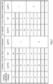
- FIG. 6 is a diagram to show examples of associations of TDD UL/DL configurations and sensing patterns.
- Config.” indicates TDD UL/DL configurations
- Subframe index indicates the types of subframes corresponding to the UL/DL configurations.
- D stands for downlink (DL) subframes
- U stands for uplink (UL) subframes
- S stands for special subframes or sensing subframes.
- the special subframes are all used as sensing subframes.
- the special subframe can be seen as DL subframes, so that, in other words, in FIG. 6 , the DL subframes that neighbor (that immediately precede) UL subframes are configured as sensing subframes. Consequently, in UL/DL configurations ⁇ 0, 1, 2, 6 ⁇ , the sensing period is 5 ms, and, in UL/DL configurations 3 to 5, the sensing period is 10 ms. Also, in UL/DL configurations 0 to 6, the number of UL subframes that follow after the sensing subframes is one to three, so that the channel-occupying time to be determined based on LBT results is 1 to 3 ms.
- a radio base station reports the sensing pattern to a user terminal by using higher layer signaling (for example, RRC signaling), broadcast information (for example, SIB 1) and so on.
- the sensing pattern may be reported with the UL/DL configuration, or, if the sensing pattern is associated with a UL/DL configuration in advance, the UL/DL configuration may be reported so as to report the sensing pattern implicitly. For example, in the event of Config. 2, (Special subframes, 5 ms) may be reported explicitly as the sensing pattern, or, when Config. 2 is reported as the UL/DL configuration, the user terminal may interpret this as an implicit report of (Special subframes, 5 ms).
- UL/DL configurations configurations that are different from UL/DL configurations 0 to 6 shown in FIG. 6 may be used, and, in that case, the DL subframes that neighbor (that immediately precede) UL subframes may be made sensing subframes.
- method 1 methods of configuring the length of each period (LBT, GP and Report) included in sensing subframes will be described.
- conventional (LTE Rel. 11) special subframe configurations are re-used as sensing subframe configurations.
- the lengths of DwPTS, GP and UpPTS in special subframes are used as the lengths of LBT, GP and Report in sensing subframes, respectively.
- FIG. 7 is a diagram to show examples of special subframe configurations in TDD.
- “Special subframe config.” indicates special subframe configurations.
- the lengths of DwPTS, GP and UpPTS are given in symbol units.
- the lengths of LBT, GP and Report in sensing subframes are three, ten and one OFDM symbol, respectively.
- the special subframe configurations are not limited to configurations 0 to 9 shown in FIG. 7 .
- Each special subframe configuration determines the lengths of DwPTS, GP and UpPTS. Also, each configuration is provided for the case where the normal cyclic prefix is used (the symbol duration of one subframe is 14), and the case where an extended cyclic prefix is used (the symbol duration of one subframe is 12). Note that each configuration has only to define at least two parameters, and one parameter may be removed. For example, if only DwPTS and UpPTS are defined, GP does not have to be defined. In this case, the user terminal can judge the length of GP based on the symbol duration, DwPTS and UpPTS.
- sensing subframe configurations from the special subframe configurations of ⁇ 2, 3, 4, 6, 7, 8 ⁇ (when the normal cyclic prefix is used) or ⁇ 1, 2, 3, 5, 6 ⁇ (when an extended cyclic prefix is used).
- new sensing subframe configurations are defined.
- the lengths of LBT, GP and Report in sensing subframes can be configured without relying upon the lengths of DwPTS, GP and UpPTS in special subframes, respectively.
- FIG. 8 is a diagram to show examples of sensing subframe configuration in TDD.
- “Sensing subframe config.” indicates sensing subframe configurations. Also, the lengths of DwPTS, GP and UpPTS are given in symbol units. Note that the sensing subframe configurations are not limited to configurations 0 to 9 shown in FIG. 8 . Also, the sensing subframe configurations may use different lengths of LBTs, GPs and Reports from those shown in FIG. 8 .
- the sensing subframe configurations it is preferable to structure the sensing subframe configurations to include many GPs of smaller values than the GPs in conventional (Rel. 11) special subframe configurations. By this means, it becomes possible to configure guard periods that are more suitable for small cells having relatively small coverage radii.
- the sensing subframe configurations it is preferable to structure the sensing subframe configurations to include many Reports of greater values than the UpPTSs in conventional (Rel. 11) special subframe configurations.
- the report period is extended, and it becomes possible to transmit many pieces of useful information (for example, NAV (Network Allocation Vector), BSR (Buffer Status Report), etc.).
- NAV Network Allocation Vector
- BSR Buffer Status Report
- Information about the sensing subframe configuration that is applied may be reported to the user terminal through higher layer signaling (for example, RRC signaling) and/or broadcast information (for example, SIB 1).
- RRC signaling for example, RRC signaling
- SIB 1 broadcast information
- each sensing subframe may use a different sensing subframe configuration.
- the special subframe configuration and the sensing subframe configuration to be applied to a radio frame may be selected to be different.
- FIG. 6 shows an example in which all the special subframes are used as sensing subframes, this is by no means limiting.
- a structure may be used in which, when a plurality of special subframes are present in a radio frame, part of the special subframes is used as sensing subframes.
- the special subframes that are not used as sensing subframes can be used as DL subframes, so that it is possible to maintain a relatively short sensing period (for example, ten subframes or shorter), and, furthermore, reduce the decrease of DL throughput.
- FIG. 9 is a diagram to show examples of associations of TDD UL/DL configurations and sensing patterns. Unlike the examples of FIG. 6 , in the examples of FIG. 9 , in UL/DL configurations ⁇ 0, 1, 2, 6 ⁇ , in which a plurality of special subframes are included in one frame, the special subframe of subframe 1 is made a sensing subframe, and the special subframe of subframe 6 is used as a special subframe on an as-is basis. Consequently, in UL/DL configurations 0 to 6, the sensing period is 10 ms.
- the allocation rule as to which special subframes are used as sensing subframes is by no means limited to this.
- the special subframe of subframe 6 is used as a sensing subframe
- the special subframe of subframe 1 is used as a special subframes on an as-is basis.
- the sensing period is longer than ten subframes, and in which a radio frame including no sensing subframes is present.
- the sensing period may be made 20 ms, 40 ms and 80 ms.
- special subframes that are not used as sensing subframes as DL subframes, so that it is possible to maintain executing sensing in a predetermine period, and, furthermore, reduce the decrease of DL throughput even more.
- the sensing period may be reported to the user terminal via higher layer signaling (for example, RRC signaling) and/or broadcast information (for example, SIB 1).
- the sensing patterns are not associated with TDD UL/DL configurations.
- the user terminal implicitly judges the sensing pattern to use, or uses sensing patterns that are reported explicitly.
- the user terminal judges the sensing pattern implicitly, the user terminal carries out sensing if predetermined conditions are fulfilled.
- FIG. 10 provide diagrams to show examples of sensing patterns that are configured implicitly.
- a structure may be employed, in which the sensing period is one subframe, and in which sensing is always carried out when there is data to transmit.
- the sensing pattern is (Arbitrary subframes, 1 ms).
- the sensing results in subframes 0 and 1 are “busy” and the result in subframe 2 is “free,” so that the user terminal can execute transmission in, for example, subframe 3.
- a structure to execute sensing on a per subframe basis makes the time to wait for sensing short and enables transmission with low delays, sensing is performed with high frequency, and this results in increased power consumption.
- a structure may be employed in which the sensing period is changed depending on the number of times sensing is performed in order to transmit this data. For example, when the sensing result is “busy,” the user terminal may change the sensing period by determining the next sensing subframe based on following table 1:
- i is the number of times sensing is performed (the number of times to wait for transmission)
- SF current is the current subframe.
- the result of sensing in subframe 8 is “free,” so that the user terminal can start the transmission process.
- a structure to change the sensing period depending on the number of times to try sensing makes possible a trade-off between delay and power consumption.
- the implicit sensing patterns are not limited to these.
- a structure may be employed here in which sensing is carried out for every several subframes, instead of carrying out sensing on a per subframe basis.
- a structure may be employed in which the sensing period is made long depending the number of times of sensing.
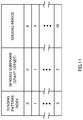
- FIG. 11 is a diagram to show examples of sensing patterns that are reported explicitly.
- “Sensing pattern index” indicates the indices of sensing patterns.
- FIG. 11 shows sensing patterns that presume periodic sensing, and one sensing pattern is associated with a sensing subframe start offset (that is, the index of the minimum sensing subframe in one frame) and a sensing period. For example, referring to FIG. 11 , when the sensing pattern index is 0, the sensing subframe is 0, and the sensing period is 6.
- the sensing patterns may be cell-specific.
- the radio base stations forming each cell report cell-specific sensing patterns to the user terminals in each cell by using broadcast information (for example, SIB 1).
- the sensing patterns may be user terminal-specific.
- the radio base stations report user terminal-specific sensing patterns to the user terminals by using higher layer signaling (for example, RRC signaling).
- FIG. 12 provide diagrams to show examples in which cell-specific sensing patterns are reported explicitly.
- UE 1 is connected with unlicensed band cell 1
- UE 2 is connected with unlicensed band cell 2 .
- Cell 1 reports sensing pattern 0 (see FIG. 11 ), which is the subject cell's sensing pattern, to UE 1 , which is a serving user terminal
- cell 2 reports sensing pattern 1 (see FIG. 11 ), which is the subject cell's sensing pattern, to UE 2 , which is a serving user terminal.
- radio base stations cells
- a structure may be employed here in which radio base stations (cells) report the sensing patterns used in the subject cells to each other, or a structure may be employed in which radio base stations select and use sensing patterns that are from those of other cells.
- FIG. 13 provide diagrams to show examples of cases where user terminal-specific sensing patterns are reported explicitly.
- UE 1 and UE 2 are connected with licensed band cell 0 and unlicensed band cell 1 .
- Cell 0 reports, to UE 1 and UE 2 , which are serving user terminals, sensing patterns 0 and 1 (see FIG. 11 ), which are the sensing patterns of these. Note that it is equally possible to employ a structure to report user terminal-specific sensing patterns from the unlicensed band cell.
- the user terminals are not limited to combinations that are determined based on sensing patterns, and are able to execute sensing adequately.
- the sensing subframe configurations may use configurations to include an LBT, a GP and a Report.
- the user terminal may, as has been described with the first embodiment, decide the length of each period in sensing subframes based on the special subframe configurations in TDD, newly defined sensing subframe configurations and so on.
- the sensing subframe configurations of the second embodiment are by no means limited to configurations including an LBT, a GP and a Report. For example, it is possible to make the whole of a sensing subframe the LBT time.
- the sensing subframe start offset, the sensing period and the sensing subframe configuration may be reported on a per cell basis, by using broadcast information (for example, SIB 1), or may be reported on a per user terminal basis by using higher layer signaling (for example, RRC signaling). It is preferable to report these on a per cell basis if the sensing patterns are cell-specific, or on a per user terminal basis if the sensing patterns are user terminal-specific.
- broadcast information for example, SIB 1
- RRC signaling higher layer signaling
- the sensing pattern, the sensing period, the LBT sensing time and so on are determined so as to fulfill predetermined LBT-related restrictions (for example, restrictions by the country, region and so on).
- the sensing time, the channel-occupying time and so on are determined so as to allow flexible and even use of bands with other systems that use unlicensed bands. For example, in Europe, the channel-occupying time is required to be within 1 ms at a minimum and 10 ms at a maximum.
- sensing subframes semi-statically have been described with the above first and second embodiments. Since these embodiments presume using sensing subframes in UL-LBT, for terminals that have little (or no) UL data, it is a waste to execute LBT in sensing subframes. In many cases, traffic tends to be concentrated in DL, and therefore, for example, using 20% of the resources for UL-LBT as shown with the structure of Config. 2 in FIG. 6 is a significant waste.
- the present inventors have furthermore come up with the idea of switching sensing subframes in accordance with traffic.
- the present inventors have arrived at using sensing subframes as conventional special subframes when there is DL traffic and as sensing subframes when there is UL traffic. By this means, it becomes possible to use radio resources more effectively.
- FIG. 14 is a flowchart to show an example of sensing subframe switching processes in the third embodiment.
- a user terminal judges whether or not the current subframe is a sensing subframe (step S 11 ). If the current subframe is not a sensing subframe (step S 11 : NO), the user terminal waits until the next subframe, and carries out step S 11 again.
- the user terminal If the current subframe is a sensing subframe (step S 11 : YES), the user terminal first reads the PCFICH (Physical Control Format Indicator Channel), and, based on the PCFICH, tries to receive the PDCCH (Physical Downlink Control Channel) in a predetermined OFDM symbol period (for example, in a period of one to two OFDM symbols) (step S 12 ). Alternatively, in step S 12 , the user terminal may skip receiving the PCFICH, and try receiving the PDCCH in a predetermined OFDM symbol period (for example, in a period of one to two OFDM symbols) that is configured in advance by higher layer signaling (for example, RRC signaling and so on).
- PCFICH Physical Control Format Indicator Channel
- PDCCH Physical Downlink Control Channel
- the user terminal may skip receiving the PCFICH, and try receiving the PDCCH in a predetermined OFDM symbol period (for example, in a period of one to two OFDM symbols) that is configured in advance by higher layer signal
- the user terminal judges whether or not UL data is held in the buffer (step S 13 ). If the user terminal judges that UL data is held (step S 13 : YES), as a result of step S 12 , the user terminal further judges whether or not a DL assignment to designate the PDSCH for the subject terminal is detected (step S 14 ). When judging that a DL assignment has been detected (step S 14 : YES), the user terminal performs one of the following (step S 15 ):
- the user terminal identifies the current subframe as a special subframe, pends UL-LBT (pending) and executes DL reception;
- the user terminal identifies the current subframe a sensing subframe, gives up DL reception, and performs UL-LBT.
- the user terminal receives and demodulates the PDSCH in the same way as with DwPTS in conventional special subframes.
- step S 14 if the user terminal judges that no DL assignment has been detected (step S 14 : NO), the user terminal identifies the current subframe as a sensing subframe, and executes UL-LBT (step S 16 ).
- step S 13 when the user terminal judges that no UL data is held (step S 13 : NO), the user terminal furthermore judges whether or not a DL assignment to designate the PDSCH for the subject terminal has been detected (step S 17 ).
- step S 17 When the user terminal judges that a DL assignment has been detected (step S 17 : YES), the user terminal identifies the current subframe as a special subframe, and executes DL reception (step S 18 ).
- step S 17 NO
- the user terminal may identify the current subframe as a sensing subframe and execute UL-LBT.
- step S 15 it is possible to switch between and perform the operations of Alt. 1 and Alt. 2 depending on whether or not the UL data that is held in the buffer is control information. For example, when there is UL data that includes control information, the user terminal gives up DL reception and executes UL-LBT, and, otherwise, pends UL-LBT and prioritizes DL reception. By this means, the user terminal becomes capable of transmitting control information, which is important in communication, as quickly as possible. [0097] Also, it is equally possible to use a structure in which UL-LBT is carried out in above steps S 15 and S 16 if a UL grant to command a PUSCH transmission is detected upon the reception of the PDCCH in step S 12 .
- the above-described flow presumes a case where sensing subframes are configured in advance, this is by no means limiting.
- the user terminal judges whether or not the current subframe is a special subframe in step S 11 , and performs processes of step S 12 and later steps when the current subframe is a special subframe.
- a radio base station can transmit, to a user terminal, a DL assignment to command receiving the PDSCH in the event of a special subframe, or transmit a UL grant to command transmitting the PUSCH in the event of a sensing subframe.
- the structure of the radio communication system according to one embodiment of the present invention will be described below.
- the above-described radio communication methods according to the first to third examples are employed.
- the above-described radio communication methods of the first to third examples may be applied individually or may be applied in combination.
- FIG. 15 is a diagram to show an example of a schematic structure of a radio communication system according to the present embodiment.
- the radio communication system shown in FIG. 15 is a system to incorporate, for example, an LTE system, super 3G and LTE-A system.
- This radio communication system can adopt carrier aggregation (CA) and/or dual connectivity (DC) to group a plurality of fundamental frequency blocks (component carriers) into one, where the LTE system bandwidth constitutes one unit.
- the radio communication system shown in FIG. 15 has a radio base station (for example, an LTE-U base station) that is capable of using unlicensed bands.
- this radio communication system may be referred to as “IMT-Advanced,” or may be referred to as “4G” or “FRA” (Future Radio Access).
- the radio communication system 1 shown in FIG. 15 includes a radio base station 11 that forms a macro cell C 1 , and radio base stations 12 a and 12 b that form small cells C 2 , which are placed within the macro cell C 1 and which are narrower than the macro cell C 1 . Also, the user terminals 20 are placed in the macro cell C 1 and in each small cell C 2 .
- a mode may be possible in which the macro cell C 1 is used in a licensed band and the small cells C 2 are used in unlicensed bands (LTE-U). Also, a mode may be also possible in which part of the small cells is used in a licensed band and the rest of the small cells are used in unlicensed bands.
- the user terminals 20 can connect with both the radio base station 11 and the radio base stations 12 .
- the user terminals 20 may use the macro cell C 1 and the small cells C 2 , which use different frequencies, at the same time, by means of CA or DC.
- assist information for example, the DL signal configuration
- a radio base station 12 which is, for example, an LTE-U base station
- a structure may be employed here in which, when CA is used between a licensed band and an unlicensed band, one radio base station (for example, the radio base station 11 ) controls the scheduling of licensed band cells and unlicensed band cells.
- the radio base station 12 controls the scheduling of unlicensed band cells.
- a carrier of a relatively low frequency band for example, 2 GHz
- a narrow bandwidth referred to as, for example, “existing carrier,” “legacy carrier” and so on.
- a carrier of a relatively high frequency band for example, 3.5 GHz and so on
- a wide bandwidth may be used, or the same carrier as that used in the radio base station 11 may be used.
- wire connection optical fiber, the X2 interface, etc.
- radio connection may be established.
- the radio base station 11 and the radio base stations 12 are each connected with a higher station apparatus 30 , and are connected with a core network 40 via the higher station apparatus 30 .
- the higher station apparatus 30 may be, for example, an access gateway apparatus, a radio network controller (RNC), a mobility management entity (MME) and so on, but is by no means limited to these.
- RNC radio network controller
- MME mobility management entity
- each radio base station 12 may be connected with the higher station apparatus 30 via the radio base station 11 .
- the radio base station 11 is a radio base station having a relatively wide coverage, and may be referred to as a “macro base station,” a “central node,” an “eNB” (eNodeB), a “transmitting/receiving point” and so on.
- the radio base stations 12 are radio base stations having local coverages, and may be referred to as “small base stations,” “micro base stations,” “pico base stations,” “femto base stations,” “HeNBs” (Home eNodeBs), “RRHs” (Remote Radio Heads), “transmitting/receiving points” and so on.
- the radio base stations 11 and 12 will be collectively referred to as a “radio base station 10 ,” unless specified otherwise.
- the user terminals 20 are terminals to support various communication schemes such as LTE, LTE-A and so on, and may be either mobile communication terminals or stationary communication terminals.
- OFDMA Orthogonal Frequency Division Multiple Access
- SC-FDMA Single-Carrier Frequency Division Multiple Access
- OFDMA is a multi-carrier transmission scheme to perform communication by dividing a frequency band into a plurality of narrow frequency bands (subcarriers) and mapping data to each subcarrier.
- SC-FDMA is a single-carrier transmission scheme to mitigate interference between terminals by dividing the system band into bands formed with one or continuous resource blocks per terminal, and allowing a plurality of terminals to use mutually different bands. Note that the uplink and downlink radio access schemes are by no limited to combinations of these.
- a downlink shared channel (PDSCH: Physical Downlink Shared CHannel), which is used by each user terminal 20 on a shared basis, a broadcast channel (PBCH: Physical Broadcast Channel) and downlink L 1 /L 2 control channels are used as downlink channels.
- PDSCH Physical Downlink Shared CHannel
- PBCH Physical Broadcast Channel
- SIBs System Information Blocks
- MIBs Master Information Block
- the downlink L 1 /L 2 control channels include a PDCCH (Physical Downlink Control Channel), an EPDCCH (Enhanced Physical Downlink Control Channel), a PCFICH (Physical Control Format Indicator Channel), a PHICH (Physical Hybrid-ARQ Indicator Channel) and so on.
- PDCCH Physical Downlink Control Channel
- EPDCCH Enhanced Physical Downlink Control Channel
- PCFICH Physical Control Format Indicator Channel
- PHICH Physical Hybrid-ARQ Indicator Channel
- ACKs/NACKs HARQ delivery acknowledgement signals
- the EPDCCH is frequency-division-multiplexed with the PDSCH (downlink shared data channel), and may be used to communicate DCI, like the PDCCH.
- an uplink shared channel (PUSCH: Physical Uplink Shared Channel), which is used by each user terminal 20 on a shared basis, an uplink control channel (PUCCH: Physical Uplink Control Channel), a random access channel (PRACH: Physical Random Access Channel) and so on are used as uplink channels.
- PUSCH Physical Uplink Shared Channel
- PUCCH Physical Uplink Control Channel
- PRACH Physical Random Access Channel
- RA preambles Random access preambles for establishing connections with cells are communicated by the PRACH.
- FIG. 16 is a diagram to show an example of an overall structure of a radio base station 10 (which may be either a radio base station 11 or 12 ) according to the present embodiment.
- the radio base station 10 has a plurality of transmitting/receiving antennas 101 for MIMO communication, amplifying sections 102 , transmitting/receiving sections 103 , a baseband signal processing section 104 , a call processing section 105 and a communication path interface 106 .
- the transmitting/receiving sections 103 may be comprised of transmitting sections and receiving sections.
- User data to be transmitted from the radio base station 10 to a user terminal 20 on the downlink is input from the higher station apparatus 30 to the baseband signal processing section 104 , via the communication path interface 106 .
- the baseband signal processing section 104 performs transmission processes such as a PDCP (Packet Data Convergence Protocol) layer process, division and coupling of user data, RLC (Radio Link Control) layer transmission processes such as an RLC retransmission control, MAC (Medium Access Control) retransmission control (for example, an HARQ (Hybrid Automatic Repeat reQuest) transmission process), scheduling, transport format selection, channel coding, an inverse fast Fourier transform (IFFT) process and a precoding process, and the result is forwarded to each transmitting/receiving section 103 .
- downlink control signals are also subjected to transmission processes such as channel coding and an inverse fast Fourier transform, and forwarded to each transmitting/receiving section 103 .
- the baseband signal processing section 104 reports, to the user terminal 20 , control information for allowing communication in the cell, through higher layer signaling (for example, RRC signaling, broadcast information and so on).
- the information for allowing communication in the cell includes, for example, the system bandwidth on the uplink, the system bandwidth on the downlink, and so on.
- assist information (for example, DL TPC information and so on) that relates to unlicensed band communication may be reported from a radio base station (for example, the radio base station 11 ) to the user terminal 20 in a licensed band.
- Each transmitting/receiving section 103 converts baseband signals that are pre-coded and output from the baseband signal processing section 104 on a per antenna basis, into a radio frequency band.
- the radio frequency signals having been subjected to frequency conversion in the transmitting/receiving sections 103 are amplified in the amplifying sections 102 , and transmitted from the transmitting/receiving antennas 101 .
- transmitters/receivers, transmitting/receiving circuits or transmitting/receiving devices that can be described based on common understanding of the technical field to which the present invention pertains can be used.
- radio frequency signals that are received in each transmitting/receiving antenna 101 are amplified in each amplifying section 102 .
- Each transmitting/receiving section 103 receives uplink signals amplified in the amplifying sections 102 .
- the received signals are converted into the baseband signal through frequency conversion in the transmitting/receiving sections 103 and output to the baseband signal processing section 104 .
- the user data that is included in the input uplink signals is subjected to a fast Fourier transform (FFT) process, an inverse discrete Fourier transform (IDFT) process, error correction decoding, a MAC retransmission control receiving process and RLC layer and PDCP layer receiving processes, and the result is forwarded to the higher station apparatus 30 via the communication path interface 106 .
- the call processing section 105 performs call processing such as setting up and releasing communication channels, manages the state of the radio base station 10 and manages the radio resources.
- the communication path interface 106 transmits and receives signals to and from the higher station apparatus 30 via a predetermined interface.
- the communication path interface 106 transmits and receives signals to and from neighboring radio base stations 10 (backhaul signaling) via an inter-base station interface (for example, optical fiber, the X2 interface, etc.).
- the communication path interface 106 may transmit and receive TDD UL/DL configurations, special subframe configurations, sensing subframe configurations, sensing patterns and so on with neighboring radio base stations 10 .
- FIG. 17 is a diagram to show an example of a functional structure of a radio base station according to the present embodiment. Note that, although FIG. 17 primarily shows functional blocks that pertain to characteristic parts of the present embodiment, the radio base station 10 has other functional blocks that are necessary for radio communication as well.
- the baseband signal processing section 104 provided in the radio base station 10 has a control section (scheduler) 301 , a transmission signal generating section 302 , a mapping section 303 and a receiving process section 304 .
- the control section (scheduler) 301 controls the scheduling of (for example, allocates resources to) downlink data signals that are transmitted in the PDSCH and downlink control signals that are communicated in the PDCCH and/or the enhanced PDCCH (EPDCCH). Also, the control section 301 controls the scheduling of downlink reference signals such as system information, synchronization signals, the CRS (Cell-specific Reference Signal), the CSI-RS (Channel State Information Reference Signal) and so on. Also, the control section 301 also controls the scheduling of uplink data signals that are transmitted in the PUSCH, uplink control signals that are transmitted in the PUCCH and/or the PUSCH, RA preambles that are transmitted in the PRACH, and so on.
- downlink reference signals such as system information, synchronization signals, the CRS (Cell-specific Reference Signal), the CSI-RS (Channel State Information Reference Signal) and so on.
- the control section 301 also controls the scheduling of uplink data signals that are transmitted in the PUSCH, uplink control signals
- control section 301 might control communication in licensed band cells and unlicensed band cells.
- a controller, a control circuit or a control device that can be described based on common understanding of the technical field to which the present invention pertains can be used.
- control section 301 controls the sensing patterns and/or the sensing subframe configurations which the user terminals 20 use. For example, the control section 301 may determine sensing patterns in association with TDD UL/DL configurations (first embodiment). Also, the control section 301 may determine sensing patterns without associating these with TDD UL/DL configurations (second embodiment).
- control section 301 may judge the state of interference in the radio base station 10 and/or the user terminals 20 by using the measurement results in the receiving process section 304 , feedback reports from the user terminals 20 , and so on, and determine the sensing patterns and/or the sensing subframe configurations. Also, the number of user terminals in cells, each user terminal's priority in transmission, uplink/downlink traffic and so on may be used to determine the sensing patterns and/or the sensing subframe configurations.
- the control section 301 outputs the determined sensing patterns and/or sensing subframe configurations to the transmission signal generating section 302 , and controls the mapping section 303 to map signals including these pieces of information. Note that the sensing patterns and/or the like may be associated with other pieces of information and reported implicitly, instead of being reported in explicit signals.
- the transmission signal generating section 302 generates DL signals (downlink control signals, downlink data signals, downlink reference signals and so on) based on commands from the control section 301 , and outputs these signals to the mapping section 303 .
- the transmission signal generating section 302 generates DL assignments, which report downlink signal allocation information, and UL grants, which report uplink signal allocation information, based on commands from the control section 301 .
- the downlink data signals are subjected to a coding process and a modulation process, based on coding rates and modulation schemes that are determined based on channel state information (CSI) from each user terminal 20 .
- CSI channel state information
- the mapping section 303 controls the allocation of the downlink signals generated in the transmission signal generating section 302 to radio resources based on commands from the control section 301 .
- a mapping circuit or a mapper that can be described based on common understanding of the technical field to which the present invention pertains can be used.
- the receiving process section 304 performs receiving processes (for example, demapping, demodulation, decoding and so on) of UL signals (for example, delivery acknowledgement signals (HARQ-ACK), data signals that are transmitted in the PUSCH and so on) transmitted from the user terminals. Also, the receiving process section 304 may measure the received power (RSRP), channel states and so on by using the received signals. Note that the processing results and measurement results may be output to the control section 301 .
- a signal processor/measurer, or a signal processing circuit/measurement circuit that can be described based on common understanding of the technical field to which the present invention pertains can be used.
- the receiving process section 304 receives and demodulates the PUSCH in the radio resources designated by predetermined information, based on commands from the control section 301 .
- FIG. 18 is a diagram to show an example of an overall structure of a user terminal according to the present embodiment.
- a user terminal 20 has a plurality of transmitting/receiving antennas 201 for MIMO communication, amplifying sections 202 , transmitting/receiving sections 203 , a baseband signal processing section 204 and an application section 205 .
- the transmitting/receiving sections 203 may be comprised of transmitting sections and receiving sections.
- Radio frequency signals that are received in a plurality of transmitting/receiving antennas 201 are each amplified in the amplifying sections 202 .
- Each transmitting/receiving section 203 receives the downlink signals amplified in the amplifying sections 202 .
- the received signals are subjected to frequency conversion and converted into the baseband signal in the transmitting/receiving sections 203 , and then output to the baseband signal processing section 204 .
- transmitters/receivers, transmitting/receiving circuits or transmitting/receiving devices that can be described based on common understanding of the technical field to which the present invention pertains can be used.
- the transmitting/receiving sections 203 are capable of transmitting/receiving UL/DL signals in unlicensed bands. Note that the transmitting/receiving section 203 may be capable of transmitting/receiving UL/DL signals in licensed bands as well.
- the baseband signals that are input are subjected to an FFT process, error correction decoding, a retransmission control receiving process and so on.
- Downlink user data is forwarded to the application section 205 .
- the application section 205 performs processes related to higher layers above the physical layer and the MAC layer, and so on. Furthermore, in the downlink data, broadcast information is also forwarded to the application section 205 .
- uplink user data is input from the application section 205 to the baseband signal processing section 204 .
- a retransmission control transmission process for example, an HARQ transmission process
- channel coding for example, precoding
- DFT discrete Fourier transform
- IFFT IFFT
- the baseband signal that is output from the baseband signal processing section 204 is converted into a radio frequency band in the transmitting/receiving sections 203 .
- the radio frequency signals that are subjected to frequency conversion in the transmitting/receiving sections 203 are amplified in the amplifying sections 202 , and transmitted from the transmitting/receiving antennas 201 .
- FIG. 19 is a diagram to show an example of a functional structure of a user terminal according to the present embodiment. Note that, although FIG. 19 primarily shows functional blocks that pertain to characteristic parts of the present embodiment, the user terminal 20 has other functional blocks that are necessary for radio communication as well.
- the baseband signal processing section 204 provided in the user terminal 20 has a control section 401 , a transmission signal generating section 402 , a mapping section 403 and a receiving process section 404 .
- the control section 401 acquires the downlink control signals (signals transmitted in the PDCCH/EPDCCH) and downlink data signals (signals transmitted in the PDSCH) transmitted from the radio base station 10 from the received signal processing section 404 .
- the control section 401 controls the generation of uplink control signals (for example, delivery acknowledgement signals (HARQ-ACK) and so on) and uplink data signals based on the results of judging whether or not retransmission control is necessary for downlink control signals, downlink data signals and so on.
- the control section 401 controls the transmission signal generating section 402 and the mapping section 403 .
- a controller or a control device that can be described based on common understanding of the technical field to which the present invention pertains can be used.
- control section 401 has a function for learning the buffer size of UL data that is input from the application section 205 , and, when there is UL data, controls the receiving process section 404 to carry out UL-LBT in sensing subframes. Note that it is equally possible to make the receiving process section 404 perform UL-LBT even when there is no UL data.
- control section 401 may apply control so that information that is useful for PUSCH transmission is transmitted in the report period in accordance with the results of LBT input from the receiving process section 404 .
- the control section 401 controls predetermined subframes as sensing subframes based on the sensing pattern.
- the control section 401 may learn the sensing pattern from an explicit report (first and second embodiments), or learn the sensing pattern implicitly (second embodiment).
- the control section 401 may count the number of times sensing is tried in the receiving process section 404 , and calculate and acquire the sensing pattern based on the number of times sensing is tried (see, for example, table 1).
- control section 401 may switch between using each sensing subframe as a sensing subframe and as a special subframe (third embodiment). For example, when a subframe is designated as a sensing subframe, the control section 401 controls the receiving process section 404 to try receiving the PDCCH in a predetermined OFDM symbol period based on the PCFICH. Then, when a report arrives from the receiving process section 404 to the effect that a DL assignment has been detected in the sensing subframe, the control section 401 makes the receiving process section 404 carry out DL reception or carry out UL-LBT.
- the transmission signal generating section 402 generates UL signals (uplink control signals, uplink data signals, uplink reference signals and so on) based on commands from the control section 401 , and outputs these signals to the mapping section 403 .
- the transmission signal generating section 402 generates uplink control signals such as delivery acknowledgement signals (HARQ-ACK), channel state information (CSI) and so on, based on commands from the control section 401 .
- the transmission signal generating section 402 generates uplink data signals based on commands from the control section 401 .
- HARQ-ACK delivery acknowledgement signals
- CSI channel state information
- the transmission signal generating section 402 generates uplink data signals based on commands from the control section 401 .
- the control section 401 commands the uplink data signal 403 to generate an uplink data signal.
- a signal generator or a signal generating circuit that can be described based on common understanding of the technical field to which the present invention pertains can be used.
- the mapping section 403 maps the uplink signals generated in the transmission signal generating section 402 to radio resources based on commands from the control section 401 , and outputs these to the transmitting/receiving sections 203 .
- a mapping circuit or a mapper that can be described based on common understanding of the technical field to which the present invention pertains can be used.
- the receiving process section 404 performs receiving processes (for example, demapping, demodulation, decoding and so on) of the DL signals transmitted in licensed bands and unlicensed bands (for example, downlink control signals transmitted from the radio base station, downlink data signals transmitted in the PDSCH, and so on).
- the receiving process section 404 When receiving the TDD UL/DL configuration, the special subframe configuration, the sensing subframe configuration, the sensing pattern and so on from the radio base station 10 , the receiving process section 404 outputs these to the control section 401 .
- the receiving process section 404 may measure the received power (RSRP), channel states and so on by using these received signals. Note that the processing results and measurement results may be output to the control section 401 .
- RSRP received power
- a signal processor/measurer, or a signal processing circuit/measurement circuit that can be described based on common understanding of the technical field to which the present invention pertains can be used.
- the receiving process section 404 executes LBT in an unlicensed band by using predetermined subframes (for example, special subframes) as sensing subframes based on commands from the control section 401 , and outputs the results of LBT (for example, the results of judging whether or not the channel state is clear or busy) to the control section 401 .
- predetermined subframes for example, special subframes
- the results of LBT for example, the results of judging whether or not the channel state is clear or busy
- the receiving process section 404 tries to receive the PDCCH in a predetermined OFDM symbol period based on commands from the control section 401 , based on the PCFICH. Then, when the receiving process section 404 detects a DL assignment to designate the PDSCH for the subject terminal, the receiving section 404 sends a report to that effect to the control section 401 .
- each functional block may be implemented in arbitrary combinations of hardware and software. Also, means for implementing each functional block is not particularly limited. That is, each functional block may be implemented with one physically-integrated device, or may be implemented by connecting two physically separate devices via radio or wire and using these multiple devices.
- radio base stations 10 and user terminals 20 may be implemented using hardware such as ASICs (Application-Specific Integrated Circuits), PLDs (Programmable Logic Devices), FPGAs (Field Programmable Gate Arrays), and so on.
- the radio base stations 10 and the user terminals 20 may be implemented with a computer device that includes a processor (CPU), a communication interface for connecting with networks, a memory and a computer-readable storage medium that holds programs.
- the processor and the memory are connected with a bus for communicating information.
- the computer-readable recording medium is a storage medium such as, for example, a flexible disk, an optomagnetic disk, a ROM, an EPROM, a CD-ROM, a RAM, a hard disk and so on.
- the programs may be transmitted from the network through, for example, electric communication channels.
- the radio base stations 10 and the user terminals 20 may include input devices such as input keys and output devices such as displays.
- the functional structures of the radio base stations 10 and the user terminals 20 may be implemented with the above-described hardware, may be implemented with software modules that are executed on the processor, or may be implemented with combinations of both.
- the processor controls the whole of the user terminals by allowing the operating system to work. Also, the processor reads programs, software modulates and data from the storage medium into the memory, and executes various types of processes. Here, these programs have only to be programs that make a computer execute each operation that has been described with the above embodiments.
- the control section 401 of the user terminals 20 may be stored in the memory and implemented by a control program that operates on the processor, and other functional blocks may be implemented likewise.
Landscapes
- Engineering & Computer Science (AREA)
- Signal Processing (AREA)
- Computer Networks & Wireless Communication (AREA)
- Physics & Mathematics (AREA)
- Health & Medical Sciences (AREA)
- General Health & Medical Sciences (AREA)
- Spectroscopy & Molecular Physics (AREA)
- Mobile Radio Communication Systems (AREA)
- Time-Division Multiplex Systems (AREA)
Abstract
Description
| TABLE 1 | |||
| Sensing period | Sensing period (ms) | ||
| i ≤ 5 | (SFcurrent + 25−i) |
25−i | ||
| i > 5 | (SFcurrent + 1) |
1 | ||
Claims (4)
Priority Applications (1)
| Application Number | Priority Date | Filing Date | Title |
|---|---|---|---|
| US16/244,969 US11218883B2 (en) | 2014-07-31 | 2019-01-10 | User terminal, radio base station, radio communication method and radio communication system |
Applications Claiming Priority (4)
| Application Number | Priority Date | Filing Date | Title |
|---|---|---|---|
| JP2014156209 | 2014-07-31 | ||
| JP2014-156209 | 2014-07-31 | ||
| PCT/JP2015/068990 WO2016017355A1 (en) | 2014-07-31 | 2015-07-01 | User terminal, wireless base station, wireless communication method, and wireless communication system |
| US16/244,969 US11218883B2 (en) | 2014-07-31 | 2019-01-10 | User terminal, radio base station, radio communication method and radio communication system |
Related Parent Applications (2)
| Application Number | Title | Priority Date | Filing Date |
|---|---|---|---|
| US15/500,635 Continuation US20170223550A1 (en) | 2014-07-31 | 2015-07-01 | User terminal, radio base station, radio communication method and radio communication system |
| PCT/JP2015/068990 Continuation WO2016017355A1 (en) | 2014-07-31 | 2015-07-01 | User terminal, wireless base station, wireless communication method, and wireless communication system |
Publications (2)
| Publication Number | Publication Date |
|---|---|
| US20190150000A1 US20190150000A1 (en) | 2019-05-16 |
| US11218883B2 true US11218883B2 (en) | 2022-01-04 |
Family
ID=55217259
Family Applications (2)
| Application Number | Title | Priority Date | Filing Date |
|---|---|---|---|
| US15/500,635 Abandoned US20170223550A1 (en) | 2014-07-31 | 2015-07-01 | User terminal, radio base station, radio communication method and radio communication system |
| US16/244,969 Active US11218883B2 (en) | 2014-07-31 | 2019-01-10 | User terminal, radio base station, radio communication method and radio communication system |
Family Applications Before (1)
| Application Number | Title | Priority Date | Filing Date |
|---|---|---|---|
| US15/500,635 Abandoned US20170223550A1 (en) | 2014-07-31 | 2015-07-01 | User terminal, radio base station, radio communication method and radio communication system |
Country Status (4)
| Country | Link |
|---|---|
| US (2) | US20170223550A1 (en) |
| JP (2) | JPWO2016017355A1 (en) |
| CN (2) | CN111935720B (en) |
| WO (1) | WO2016017355A1 (en) |
Families Citing this family (17)
| Publication number | Priority date | Publication date | Assignee | Title |
|---|---|---|---|---|
| CN114615752B (en) * | 2015-08-13 | 2025-10-28 | 苹果公司 | Energy detection threshold adaptation for LTE licensed assisted access in unlicensed bands |
| US11452091B2 (en) * | 2016-02-04 | 2022-09-20 | Acer Incorporated | Device and method of handling hybrid automatic repeat request transmission |
| CN107295694B (en) * | 2016-03-30 | 2021-07-06 | 上海诺基亚贝尔股份有限公司 | A method for implementing uplink channel access in eLAA-based communication system |
| JP6239672B2 (en) * | 2016-03-31 | 2017-11-29 | 株式会社Nttドコモ | User terminal, radio base station, and radio communication method |
| US10959254B2 (en) * | 2016-03-31 | 2021-03-23 | Huawei Technologies Co., Ltd. | Radio communications method, base station, and terminal |
| US10420135B2 (en) | 2016-04-01 | 2019-09-17 | HFI Innovation | Physical random access channel design in eLAA |
| EP4106391A1 (en) * | 2016-04-01 | 2022-12-21 | Telefonaktiebolaget LM Ericsson (publ) | Methods for controlling relative measurements in the presence of lbt |
| JP6404256B2 (en) | 2016-04-14 | 2018-10-10 | 株式会社Nttドコモ | User terminal and wireless communication method |
| US10517021B2 (en) | 2016-06-30 | 2019-12-24 | Evolve Cellular Inc. | Long term evolution-primary WiFi (LTE-PW) |
| JP7301870B2 (en) | 2018-06-20 | 2023-07-03 | オッポ広東移動通信有限公司 | Channel access method, device and program for physical random access channel transmission |
| JP2020053870A (en) | 2018-09-27 | 2020-04-02 | ソニー株式会社 | Communication device, control device, and communication system |
| EP3734885A1 (en) * | 2019-05-02 | 2020-11-04 | Panasonic Intellectual Property Corporation of America | User equipment and network node involved in communication |
| US20200413440A1 (en) * | 2019-06-28 | 2020-12-31 | Qualcomm Incorporated | Automatic detection of a pattern of dynamic transmission boundaries |
| CN112654099B (en) * | 2020-12-04 | 2023-01-06 | 京信网络系统股份有限公司 | Air interface interception method, device, system and medium based on LBT |
| US12295033B2 (en) * | 2021-04-02 | 2025-05-06 | Qualcomm Incorporated | Network configured sensing bandwidth and channel occupancy time (COT) sharing |
| CN119316939A (en) * | 2023-07-12 | 2025-01-14 | 中国移动通信有限公司研究院 | Signal sending method, receiving method, device, equipment and storage medium |
| WO2025183875A1 (en) * | 2024-02-28 | 2025-09-04 | Qualcomm Incorporated | Time division duplex (tdd) sensing slot patterns |
Citations (13)
| Publication number | Priority date | Publication date | Assignee | Title |
|---|---|---|---|---|
| US20050026639A1 (en) * | 2003-07-14 | 2005-02-03 | Michael Lewis | System operable to transmit and receive messages |
| US20100098012A1 (en) | 2008-10-20 | 2010-04-22 | Interdigital Patent Holdings, Inc. | Uplink control information transmission methods for carrier aggregation |
| US20130163543A1 (en) * | 2011-12-22 | 2013-06-27 | Interdigital Patent Holdings, Inc. | Control signaling in lte carrier aggregation |
| WO2013112983A2 (en) | 2012-01-26 | 2013-08-01 | Interdigital Patent Holdings, Inc. | Dynamic parameter adjustment for lte coexistence |
| GB2498988A (en) | 2012-02-02 | 2013-08-07 | Renesas Mobile Corp | Transmission power selection in a carrier aggregation system within a shared band |
| WO2013126858A1 (en) | 2012-02-24 | 2013-08-29 | Interdigital Patent Holdings, Inc. | Random access in dynamic and shared spectrums |
| US20130286882A1 (en) * | 2011-01-05 | 2013-10-31 | Lg Electronics Inc. | Method and device for performing terminal-to-terminal cooperative communication in wireless access system |
| US20130322279A1 (en) | 2012-05-31 | 2013-12-05 | Interdigital Patent Holdings, Inc. | Sensing measurement configuration and reporting in a long term evolution system operating over license exempt bands |
| US20130343305A1 (en) | 2012-06-26 | 2013-12-26 | Futurewei Technologies, Inc. | System and Method for Allocating Periodic Resources |
| US20130343288A1 (en) | 2012-06-21 | 2013-12-26 | Nokia Corporation | Power Control For LTE Deployment In Unlicensed Band |
| US20140192767A1 (en) * | 2012-12-14 | 2014-07-10 | Futurewei Technologies, Inc. | System and Method for Small Traffic Transmissions |
| US20150365880A1 (en) | 2014-06-13 | 2015-12-17 | Qualcomm Incorporated | Wireless communications over unlicensed radio frequency spectrum |
| US20150365790A1 (en) * | 2014-06-13 | 2015-12-17 | Qualcomm Incorporated | Positioning beacons with wireless backhaul |
Family Cites Families (9)
| Publication number | Priority date | Publication date | Assignee | Title |
|---|---|---|---|---|
| KR20060015649A (en) * | 2003-06-17 | 2006-02-17 | 코닌클리즈케 필립스 일렉트로닉스 엔.브이. | System and method for adjusting radio resource usage in unlicensed frequency band and wireless device |
| JP5339433B2 (en) * | 2009-03-02 | 2013-11-13 | 株式会社エヌ・ティ・ティ・ドコモ | Transmitter, receiver, power amplification method, and signal demodulation method |
| JP5068832B2 (en) * | 2010-02-16 | 2012-11-07 | 株式会社エヌ・ティ・ティ・ドコモ | Base station apparatus and method in mobile communication system |
| US8804536B2 (en) * | 2010-08-16 | 2014-08-12 | Qualcomm Incorporated | Method and apparatus for facilitating sensing in cognitive radio communications |
| WO2012040520A1 (en) * | 2010-09-23 | 2012-03-29 | Interdigital Patent Holdings, Inc. | Channel access systems and methods for cognitive relaying for cellular systems |
| US9363798B2 (en) * | 2011-03-11 | 2016-06-07 | Lg Electronics Inc. | Method and device for terminal to transmit/receive signal in wireless communication system having carrier aggregation technique applied thereto |
| WO2013030732A1 (en) * | 2011-08-26 | 2013-03-07 | Renesas Mobile Corporation | Apparatus and method for communication |
| EP2795953A1 (en) * | 2011-12-22 | 2014-10-29 | Interdigital Patent Holdings, Inc. | Methods, apparatus, and systems for dynamic spectrum allocation |
| JP5952717B2 (en) * | 2012-11-05 | 2016-07-13 | 日本電信電話株式会社 | Wireless communication apparatus and wireless communication method |
-
2015
- 2015-07-01 CN CN202010737165.2A patent/CN111935720B/en active Active
- 2015-07-01 US US15/500,635 patent/US20170223550A1/en not_active Abandoned
- 2015-07-01 WO PCT/JP2015/068990 patent/WO2016017355A1/en not_active Ceased
- 2015-07-01 CN CN201580041235.8A patent/CN106576349A/en active Pending
- 2015-07-01 JP JP2016538231A patent/JPWO2016017355A1/en active Pending
-
2019
- 2019-01-10 US US16/244,969 patent/US11218883B2/en active Active
- 2019-11-14 JP JP2019205979A patent/JP6873214B2/en active Active
Patent Citations (16)
| Publication number | Priority date | Publication date | Assignee | Title |
|---|---|---|---|---|
| US20050026639A1 (en) * | 2003-07-14 | 2005-02-03 | Michael Lewis | System operable to transmit and receive messages |
| US20100098012A1 (en) | 2008-10-20 | 2010-04-22 | Interdigital Patent Holdings, Inc. | Uplink control information transmission methods for carrier aggregation |
| US20130286882A1 (en) * | 2011-01-05 | 2013-10-31 | Lg Electronics Inc. | Method and device for performing terminal-to-terminal cooperative communication in wireless access system |
| US20130163543A1 (en) * | 2011-12-22 | 2013-06-27 | Interdigital Patent Holdings, Inc. | Control signaling in lte carrier aggregation |
| WO2013112983A2 (en) | 2012-01-26 | 2013-08-01 | Interdigital Patent Holdings, Inc. | Dynamic parameter adjustment for lte coexistence |
| US20130208587A1 (en) * | 2012-01-26 | 2013-08-15 | Interdigital Patent Holdings, Inc. | Dynamic parameter adjustment for lte coexistence |
| GB2498988A (en) | 2012-02-02 | 2013-08-07 | Renesas Mobile Corp | Transmission power selection in a carrier aggregation system within a shared band |
| US20160164644A1 (en) | 2012-02-02 | 2016-06-09 | Broadcom Corporation | Power control for carrier aggregation on shared bands |
| US20150057011A1 (en) | 2012-02-24 | 2015-02-26 | Interdigital Patent Holdings, Inc. | Random access in dynamic and shared spectrums |
| WO2013126858A1 (en) | 2012-02-24 | 2013-08-29 | Interdigital Patent Holdings, Inc. | Random access in dynamic and shared spectrums |
| US20130322279A1 (en) | 2012-05-31 | 2013-12-05 | Interdigital Patent Holdings, Inc. | Sensing measurement configuration and reporting in a long term evolution system operating over license exempt bands |
| US20130343288A1 (en) | 2012-06-21 | 2013-12-26 | Nokia Corporation | Power Control For LTE Deployment In Unlicensed Band |
| US20130343305A1 (en) | 2012-06-26 | 2013-12-26 | Futurewei Technologies, Inc. | System and Method for Allocating Periodic Resources |
| US20140192767A1 (en) * | 2012-12-14 | 2014-07-10 | Futurewei Technologies, Inc. | System and Method for Small Traffic Transmissions |
| US20150365880A1 (en) | 2014-06-13 | 2015-12-17 | Qualcomm Incorporated | Wireless communications over unlicensed radio frequency spectrum |
| US20150365790A1 (en) * | 2014-06-13 | 2015-12-17 | Qualcomm Incorporated | Positioning beacons with wireless backhaul |
Non-Patent Citations (6)
| Title |
|---|
| 3GPP TS 36.300 V8.5.0; "3rd Generation Partnership Project; Technical Specification Group Radio Access Network Evolved Universal Terrestrial Radio Access (E-UTRA) and Evolved Universal Terrestrial Radio Access Network (E-UTRAN); Overall Description; Stage 2 (Release 8)"; May 2008 (134 pages). |
| International Search Report issued in PCT/JP2015/068990 dated Sep. 1, 2015 (1 page). |
| Office Action in counterpart Japanese Patent Application No. 2019-205979 dated Sep. 23, 2020 (6 pages). |
| Office Action issued in Chinese Application No. 201580041235.8; dated May 13, 2020 (17 pages). |
| Office Action issued in Japanese Application No. 2016-538231; dated Jan. 31, 2019 (6 pages). |
| Written Opinion of the International Searching Authority issued in PCT/JP2015/068990 dated Sep. 1, 2015 (3 pages). |
Also Published As
| Publication number | Publication date |
|---|---|
| JPWO2016017355A1 (en) | 2017-06-15 |
| CN111935720B (en) | 2024-10-15 |
| CN111935720A (en) | 2020-11-13 |
| CN106576349A (en) | 2017-04-19 |
| US20170223550A1 (en) | 2017-08-03 |
| WO2016017355A1 (en) | 2016-02-04 |
| JP2020025340A (en) | 2020-02-13 |
| US20190150000A1 (en) | 2019-05-16 |
| JP6873214B2 (en) | 2021-05-19 |
Similar Documents
| Publication | Publication Date | Title |
|---|---|---|
| US11490421B2 (en) | User terminal and radio communication method | |
| US11218883B2 (en) | User terminal, radio base station, radio communication method and radio communication system | |
| US10305719B2 (en) | Radio base station, user terminal and radio communication method | |
| US10154430B2 (en) | Radio base station, user terminal and radio communication system | |
| CN106538013B (en) | Radio base station, user terminal, and radio communication method | |
| US20200084763A1 (en) | Terminal and radio control method | |
| US9980274B2 (en) | User terminal, radio base station and radio communication method | |
| US20180020479A1 (en) | Radio base station, user terminal and radio communication method | |
| US11184123B2 (en) | Terminal and radio communication method | |
| US20180115904A1 (en) | Radio base station, user terminal, radio communication system and radio communication method | |
| US20180115975A1 (en) | Radio base station, user terminal and radio communication method | |
| US10841921B2 (en) | Radio base station, user terminal and radio communication method | |
| US20180235010A1 (en) | User terminal, radio base station and radio communication method | |
| EP3307005A1 (en) | User terminal, wireless base station, and wireless communication method |
Legal Events
| Date | Code | Title | Description |
|---|---|---|---|
| FEPP | Fee payment procedure |
Free format text: ENTITY STATUS SET TO UNDISCOUNTED (ORIGINAL EVENT CODE: BIG.); ENTITY STATUS OF PATENT OWNER: LARGE ENTITY |
|
| STPP | Information on status: patent application and granting procedure in general |
Free format text: DOCKETED NEW CASE - READY FOR EXAMINATION |
|
| STPP | Information on status: patent application and granting procedure in general |
Free format text: NON FINAL ACTION MAILED |
|
| STPP | Information on status: patent application and granting procedure in general |
Free format text: RESPONSE TO NON-FINAL OFFICE ACTION ENTERED AND FORWARDED TO EXAMINER |
|
| STPP | Information on status: patent application and granting procedure in general |
Free format text: FINAL REJECTION MAILED |
|
| STPP | Information on status: patent application and granting procedure in general |
Free format text: NON FINAL ACTION MAILED |
|
| STPP | Information on status: patent application and granting procedure in general |
Free format text: FINAL REJECTION MAILED |
|
| STPP | Information on status: patent application and granting procedure in general |
Free format text: RESPONSE AFTER FINAL ACTION FORWARDED TO EXAMINER |
|
| STPP | Information on status: patent application and granting procedure in general |
Free format text: ADVISORY ACTION MAILED |
|
| STPP | Information on status: patent application and granting procedure in general |
Free format text: DOCKETED NEW CASE - READY FOR EXAMINATION |
|
| STPP | Information on status: patent application and granting procedure in general |
Free format text: NON FINAL ACTION MAILED |
|
| STPP | Information on status: patent application and granting procedure in general |
Free format text: RESPONSE TO NON-FINAL OFFICE ACTION ENTERED AND FORWARDED TO EXAMINER |
|
| STPP | Information on status: patent application and granting procedure in general |
Free format text: NOTICE OF ALLOWANCE MAILED -- APPLICATION RECEIVED IN OFFICE OF PUBLICATIONS |
|
| STPP | Information on status: patent application and granting procedure in general |
Free format text: PUBLICATIONS -- ISSUE FEE PAYMENT VERIFIED |
|
| STCF | Information on status: patent grant |
Free format text: PATENTED CASE |
|
| MAFP | Maintenance fee payment |
Free format text: PAYMENT OF MAINTENANCE FEE, 4TH YEAR, LARGE ENTITY (ORIGINAL EVENT CODE: M1551); ENTITY STATUS OF PATENT OWNER: LARGE ENTITY Year of fee payment: 4 |