US11218696B2 - Method for image encoding and apparatus for implementing the same using interpolation filter based on motion speed - Google Patents
Method for image encoding and apparatus for implementing the same using interpolation filter based on motion speed Download PDFInfo
- Publication number
- US11218696B2 US11218696B2 US16/797,300 US202016797300A US11218696B2 US 11218696 B2 US11218696 B2 US 11218696B2 US 202016797300 A US202016797300 A US 202016797300A US 11218696 B2 US11218696 B2 US 11218696B2
- Authority
- US
- United States
- Prior art keywords
- image
- motion
- motion speed
- interpolation
- current block
- Prior art date
- Legal status (The legal status is an assumption and is not a legal conclusion. Google has not performed a legal analysis and makes no representation as to the accuracy of the status listed.)
- Active
Links
Images


Classifications
-
- H—ELECTRICITY
- H04—ELECTRIC COMMUNICATION TECHNIQUE
- H04N—PICTORIAL COMMUNICATION, e.g. TELEVISION
- H04N19/00—Methods or arrangements for coding, decoding, compressing or decompressing digital video signals
- H04N19/10—Methods or arrangements for coding, decoding, compressing or decompressing digital video signals using adaptive coding
- H04N19/102—Methods or arrangements for coding, decoding, compressing or decompressing digital video signals using adaptive coding characterised by the element, parameter or selection affected or controlled by the adaptive coding
- H04N19/117—Filters, e.g. for pre-processing or post-processing
-
- H—ELECTRICITY
- H04—ELECTRIC COMMUNICATION TECHNIQUE
- H04N—PICTORIAL COMMUNICATION, e.g. TELEVISION
- H04N19/00—Methods or arrangements for coding, decoding, compressing or decompressing digital video signals
- H04N19/10—Methods or arrangements for coding, decoding, compressing or decompressing digital video signals using adaptive coding
- H04N19/134—Methods or arrangements for coding, decoding, compressing or decompressing digital video signals using adaptive coding characterised by the element, parameter or criterion affecting or controlling the adaptive coding
- H04N19/136—Incoming video signal characteristics or properties
- H04N19/137—Motion inside a coding unit, e.g. average field, frame or block difference
- H04N19/139—Analysis of motion vectors, e.g. their magnitude, direction, variance or reliability
-
- H—ELECTRICITY
- H04—ELECTRIC COMMUNICATION TECHNIQUE
- H04N—PICTORIAL COMMUNICATION, e.g. TELEVISION
- H04N19/00—Methods or arrangements for coding, decoding, compressing or decompressing digital video signals
- H04N19/10—Methods or arrangements for coding, decoding, compressing or decompressing digital video signals using adaptive coding
- H04N19/169—Methods or arrangements for coding, decoding, compressing or decompressing digital video signals using adaptive coding characterised by the coding unit, i.e. the structural portion or semantic portion of the video signal being the object or the subject of the adaptive coding
- H04N19/17—Methods or arrangements for coding, decoding, compressing or decompressing digital video signals using adaptive coding characterised by the coding unit, i.e. the structural portion or semantic portion of the video signal being the object or the subject of the adaptive coding the unit being an image region, e.g. an object
- H04N19/176—Methods or arrangements for coding, decoding, compressing or decompressing digital video signals using adaptive coding characterised by the coding unit, i.e. the structural portion or semantic portion of the video signal being the object or the subject of the adaptive coding the unit being an image region, e.g. an object the region being a block, e.g. a macroblock
-
- H—ELECTRICITY
- H04—ELECTRIC COMMUNICATION TECHNIQUE
- H04N—PICTORIAL COMMUNICATION, e.g. TELEVISION
- H04N19/00—Methods or arrangements for coding, decoding, compressing or decompressing digital video signals
- H04N19/50—Methods or arrangements for coding, decoding, compressing or decompressing digital video signals using predictive coding
- H04N19/503—Methods or arrangements for coding, decoding, compressing or decompressing digital video signals using predictive coding involving temporal prediction
- H04N19/51—Motion estimation or motion compensation
- H04N19/523—Motion estimation or motion compensation with sub-pixel accuracy
-
- H—ELECTRICITY
- H04—ELECTRIC COMMUNICATION TECHNIQUE
- H04N—PICTORIAL COMMUNICATION, e.g. TELEVISION
- H04N19/00—Methods or arrangements for coding, decoding, compressing or decompressing digital video signals
- H04N19/50—Methods or arrangements for coding, decoding, compressing or decompressing digital video signals using predictive coding
- H04N19/503—Methods or arrangements for coding, decoding, compressing or decompressing digital video signals using predictive coding involving temporal prediction
- H04N19/51—Motion estimation or motion compensation
- H04N19/573—Motion compensation with multiple frame prediction using two or more reference frames in a given prediction direction
-
- H—ELECTRICITY
- H04—ELECTRIC COMMUNICATION TECHNIQUE
- H04N—PICTORIAL COMMUNICATION, e.g. TELEVISION
- H04N19/00—Methods or arrangements for coding, decoding, compressing or decompressing digital video signals
- H04N19/50—Methods or arrangements for coding, decoding, compressing or decompressing digital video signals using predictive coding
- H04N19/59—Methods or arrangements for coding, decoding, compressing or decompressing digital video signals using predictive coding involving spatial sub-sampling or interpolation, e.g. alteration of picture size or resolution
Definitions
- the present disclosure relates to the field of image processing, in particular for video stream compression/decompression.
- Video data is often source encoded so as to decrease the amount of resources necessary for its transmission and/or storage in memory.
- Various video coding or compression standards that have been developed over the recent years, such as H.264/AVC, H.265/HEVC or MPEG-2, may be used for that purpose.
- images also referred to as “frames” of an input video stream to be encoded are typically processed according to an image encoding sequence, and each image is divided into pixel sets (also referred to as, depending on the scheme, “blocks” or “coding unit”) which are also processed sequentially, for example starting from the set located in the upper left corner of the image, and ending with the set located in the lower right corner of the image.
- pixel sets also referred to as, depending on the scheme, “blocks” or “coding unit”
- the encoding of an image of an input video stream may therefore involve dividing a pixel matrix corresponding to the image into several pixel sets, for example into blocks of a fixed size (16 ⁇ 16 pixels, 32 ⁇ 32 pixels, or 64 ⁇ 64 pixels), and encoding these pixel blocks according to a predefined encoding sequence.
- blocks smaller than 16 ⁇ 16 pixels may be defined (for example of size 8 ⁇ 8 pixels or 4 ⁇ 4 pixels) so as to perform encoding of the image with a finer granularity.
- intra prediction video coding the compression processing uses pixels of a unique image or video frame
- inter prediction video coding the compression processing uses pixels of several images or video frames for which prediction encoding has already been performed. More specifically, in intra prediction video coding, the processing of a pixel block (or set of pixels) typically includes a prediction of the pixels of the block based on previously encoded pixels (also called “causal pixels”) in the image currently being encoded (which may be referred to as “current image”).
- current image the processing of a pixel block typically includes a prediction of the pixels of the block based on pixels of one or more previously encoded images.
- Exploiting the spatial redundancies (for intra prediction video coding) and/or temporal redundancies (for inter prediction video coding) is therefore performed to avoid transmitting or storing the pixel values of each pixel block (or set of pixels), and at least some of the blocks of each encoded image in a video stream is represented by a pixel residual that corresponds to the difference (or the distance) between prediction values and true values for the pixels of the predicted block.
- Information related to pixel residual is inserted in the encoded data generated by a video encoder after transform and quantization (e.g. Discrete Cosinus Transform, DCT) so as to reduce the entropy of data generated by the encoder.
- transform and quantization e.g. Discrete Cosinus Transform, DCT
- HEVC High Efficiency Video Coding
- H.265 reached FIDS status.
- JCT-VC Joint Collaborative Team on Video Coding
- HEVC is the successor of the H.264/AVC (Advance Video Coding) standard, which is widely used nowadays (around 90% videos are still coded with AVC).
- HEVC brings improvements compared to AVC, offering double the data compression ratio at the same level of video quality, or substantially improved video quality at the same bit rate.
- JVET Joint Video Experts Team
- VVC/H.266 Versatile Video Coding
- the primary objective of this new codec is to provide a significant improvement in compression performance over HEVC.
- the VVC standard is scheduled to be released in 2021 and by then, the aim is not just to lower the bitrate at the same video quality, but also to develop a codec which would aid the deployment of higher quality video services and emerging applications such as 360° omnidirectional immersive multimedia and High Dynamic Range (HDR) video.
- HDR High Dynamic Range
- Motion compensated prediction is a technique used by video coders to reduce the amount of information transmitted to a decoder by exploiting the temporal redundancy present in the video signal.
- MCP Motion compensated prediction
- the main role of the interpolation filter is to help predict the accurate values of pixels, if the motion does not correspond to exactly integer-pel precision. Since the H.264/AVC standard, the quarter-pel precision has been used for motion vectors, which has significantly improved the accuracy of the motion compensated prediction.
- the interpolation filter in the HEVC standard is a DCT-based interpolation filter (DCT-IF).
- DCT-IF DCT-based interpolation filter
- the VVC standard in its current standardization stage, merely inherits the DCT-IF interpolation filter from HEVC.
- Another object of the present subject disclosure is to provide an improved video encoding or compression and/or video decoding or decompression scheme and apparatuses implementing the same.
- Another object of the present subject disclosure is to provide an improved video encoding and/or decoding scheme and apparatuses implementing the same for alleviating the above-described drawbacks and shortcomings of conventional prediction-based video encoding/decoding schemes, in particular video encoding/decoding schemes using interpolation to improve motion compensation prediction.
- a method of encoding a first image in a plurality of images of input video data, wherein the first image is divided into a plurality of pixel blocks comprises, for a current block of the first image: determining a motion speed for the current block with respect to a reference block correlated to the current block in a second image of the plurality of images, wherein the second image is distinct from the first image and was previously encoded according to an image encoding sequence for encoding the images of the plurality of images; determining an interpolation filter based on the motion speed; and using the interpolation filter for calculating fractional pixel values in the second image for a temporal prediction of pixels of the current block based on the reference block of the second image.
- the present subject disclosure introduces the concept of motion adaptive interpolation, and provides several motion adaptive interpolation filter (MAIF) designs corresponding to different embodiments thereof.
- MAIF motion adaptive interpolation filter
- the proposed MAIF scheme advantageously provides an improved interpolation to be used for inter prediction coding of video data by taking into account a motion speed of a block being encoded in the determination of the interpolation filter used for calculating fractional pixel values. Such improvement in the interpolation results in improved prediction
- the interpolation used for calculating fractional pixel values for inter prediction coding of video data may be adapted dynamically based on an on-the-fly calculation of motion speed in some embodiments.
- interpolation filter parameters such as, for example, interpolation filter taps
- the present subject disclosure introduces new interpolation filter designs for inter prediction coding of video data, which advantageously simulate the behavior of a video camera when catching the motion of objects in a scene during an exposure time.
- the proposed interpolation filter designs are advantageously adaptive to motion speed, resulting in an inter prediction that is blurrier for high motion speeds (fast motions), and sharper for low motion speeds (slow motions).
- the proposed method further comprises: determining a motion vector for the current block, the motion vector pointing to the reference block in the second image, determining the motion speed based on the motion vector.
- a motion speed value may advantageously be determined based on a motion vector determined for the current block.
- the motion speed may be determined based on a norm of the motion vector, based on a temporal distance between the first and second images in the input video data, and/or based on an absolute value of the component of the motion vector in a direction of interpolation.
- the interpolation filter may be determined as a low pass filter in the frequency domain, with a cutoff frequency that is based on the motion speed.
- the interpolation filter may be determined by obtaining its transfer function as a product of a cardinal sine function, and a window function, wherein the argument of the cardinal sine function depends on the motion speed (m).
- the interpolation filter transfer function g(i) may be obtained as:
- g ⁇ ( i ) sin ⁇ ⁇ c ⁇ ( ⁇ ⁇ ( i + p ) D ⁇ ( m ) ) ⁇ w ⁇ ( i + p )
- the interpolation filter may be determined by obtaining its transfer function as a product of a cardinal sine function convolved in the time domain with a rectangular window function, and a window function, wherein the width of the rectangular window function depends on the motion speed (m).
- the interpolation filter transfer function g(i) may be obtained as:
- g ⁇ ( i ) ( sin ⁇ ⁇ c ⁇ ( ⁇ ⁇ ( i + p ) D ) * r ⁇ e ⁇ c ⁇ t m ⁇ ( i ) ) ⁇ w ⁇ ( i + p )
- the interpolation filter transfer function g(i) may be obtained as:
- g ⁇ ( i ) ( sin ⁇ ⁇ c ⁇ ( ⁇ ⁇ ( i + p ) D ⁇ ( m ) ) * r ⁇ e ⁇ c ⁇ t m ⁇ ( i ) ) ⁇ w ⁇ ( i + p )
- abs( ⁇ right arrow over (mv) ⁇ ) is based on an absolute value of the component of the motion vector in a direction of interpolation, and where j and k are positive real numbers.
- the width (w rect ) of the rectangular window may be chosen proportional to a value (noted abs( ⁇ right arrow over (mv) ⁇ ) herein) which is based on an absolute value of the component of the motion vector in a direction of interpolation.
- the transfer function of the interpolation filter may be chosen to be a function of the motion speed.
- a method of encoding a first image in a plurality of images of input video data, wherein the first image is divided into a plurality of pixel blocks which are encoded according to a block encoding sequence is proposed.
- the method comprises, for a current block of the first image: determining, via a processor of an image encoding system, a motion speed for the current block with respect to a reference block correlated to the current block in a second image of the plurality of images, wherein the second image is distinct from the first image and was previously encoded according to an image encoding sequence for encoding the images of the plurality of images; determining, via the processor, an interpolation filter based on the motion speed; and using, via the processor, the interpolation filter for calculating fractional pixel values in the second image for a temporal prediction of pixels of the current block based on the reference block of the second image.
- a method of encoding a first image in a plurality of images of input video data, wherein the first image is divided into a plurality of pixel blocks comprises, for a current block of the first image: determining an interpolation filter based on a motion speed for the current block with respect to a reference block correlated to the current block in a second image of the plurality of images, wherein the second image is distinct from the first image and was previously encoded according to an image encoding sequence for encoding the images of the plurality of images; and using the interpolation filter for calculating fractional pixel values in the second image for a temporal prediction of pixels of the current block based on the reference block of the second image.
- a method of encoding a first image in a plurality of images of input video data, wherein the first image is divided into a plurality of pixel blocks comprises: calculating fractional pixel values in a second image of the plurality of images by multiplying a plurality of integer pixel values of the second image by interpolation filter coefficients, wherein the interpolation filter coefficients are determined based on a motion speed of a current block of the first image with respect to a reference block correlated to the current block in the second image, wherein the second image is distinct from the first image and was previously encoded according to an image encoding sequence for encoding the images of the plurality of images.
- the interpolation filter coefficients may be determined based on a motion vector for the current block, the motion vector pointing to the reference block in the second image.
- an apparatus which comprises a processor, and a memory operatively coupled to the processor, wherein the apparatus is configured to perform a method as proposed in the present subject disclosure.
- a non-transitory computer-readable medium encoded with executable instructions which, when executed, causes an apparatus comprising a processor operatively coupled with a memory, to perform a method as proposed in the present subject disclosure is proposed.
- a computer program product comprising computer program code tangibly embodied in a computer readable medium, said computer program code comprising instructions to, when provided to a computer system and executed, cause said computer to perform a method as proposed in the present subject disclosure, is proposed.
- a data set representing, for example through compression or encoding, a computer program as proposed herein, is proposed.
- FIG. 1( a ) is a block diagram illustrating an exemplary video encoder on which the proposed method may be implemented in accordance with one or more embodiments;
- FIG. 1( b ) illustrates different coding block splitting modes supported by the HEVC standard, which may be used in accordance with one or more embodiments;
- FIG. 1( c ) illustrates a subdivision of an HEVC coding tree block into coding blocks and a corresponding quadtree, which may be used in accordance with one or more embodiments;
- FIG. 2( a ) illustrates motion compensation, which may be used in accordance with one or more embodiments
- FIG. 2( b ) illustrates using different pel precisions to improve the accuracy of motion compensated prediction, which may be used in accordance with one or more embodiments;
- FIG. 3( a ) is a block diagram illustrating an exemplary video processing method in accordance with one or more embodiments
- FIG. 3( b ) is a picture that illustrates high motion in a video sequence on which the proposed method may be implemented in accordance with one or more embodiments;
- FIG. 4 is a plot diagram of a cardinal sine function in accordance with one or more embodiments.
- FIG. 5( a ) is a plot diagram of a cardinal sine function in accordance with one or more embodiments
- FIG. 5( b ) is a plot diagram of rectangular window functions in accordance with one or more embodiments.
- FIG. 5( c ) is a plot diagram of convolutions of a cardinal sine function and a rectangular window function in accordance with one or more embodiments;
- FIG. 6( a ) is a plot diagram of respective impulse responses of Kaiser window functions in the time domain in accordance with one or more embodiments
- FIG. 6( b ) is a plot diagram of respective impulse responses of Kaiser window functions in the frequency domain in accordance with one or more embodiments
- FIGS. 7( a )-7( d ) are block diagrams that illustrate the operations of respective filter designs in accordance with one or more embodiments
- FIG. 8( a ) is a plot diagram of a transfer function of a Kaiser window in accordance with one or more embodiments
- FIG. 8( b ) is a plot diagram of respective transfer functions of filters in accordance with embodiments of the present subject disclosure.
- each described function, engine, block of the block diagrams and flowchart illustrations can be implemented in hardware, software, firmware, middleware, microcode, or any suitable combination thereof. If implemented in software, the functions, engines, blocks of the block diagrams and/or flowchart illustrations can be implemented by computer program instructions or software code, which may be stored or transmitted over a computer-readable medium, or loaded onto a general purpose computer, special purpose computer or other programmable data processing apparatus to produce a machine, such that the computer program instructions or software code which execute on the computer or other programmable data processing apparatus, create the means for implementing the functions described herein.
- Embodiments of computer-readable media includes, but are not limited to, both computer storage media and communication media including any medium that facilitates transfer of a computer program from one place to another.
- a “computer storage media” may be any physical media that can be accessed by a computer or a processor.
- the terms «memory» and «computer storage media” include any type of data storage device, such as, without limitation, a hard drive, a flash drive or other flash memory devices (e.g.
- various forms of computer-readable media may transmit or carry instructions to a computer, including a router, gateway, server, or other transmission device, wired (coaxial cable, fiber, twisted pair, DSL cable) or wireless (infrared, radio, cellular, microwave).
- the instructions may comprise code from any computer-programming language, including, but not limited to, assembly, C, C++, Python, Visual Basic, SQL, PHP, and JAVA.
- exemplary is used herein to mean “serving as an example, instance, or illustration”. Any embodiment or design described herein as “exemplary” is not necessarily to be construed as preferred or advantageous over other embodiments or designs.
- Coupled and “connected”, along with their derivatives, may be indifferently used to indicate that two or more elements are in direct physical or electrical contact with each other, or two or more elements are not in direct contact with each other, but yet still co-operate or interact with each other.
- the proposed process may be implemented by any video encoder, video decoder, or video codec configured for encoding and/or decoding images (or frames) of input video data using predictive coding exploiting temporal redundancies of pixel blocks in images of the input video data (e.g. inter prediction video coding), such as, for example a video encoder and/or decoder compliant with the any of the H.261, MPEG-1 Part 2, H.262, MPEG-2 Part 2, H.264/AVC, H.265/HEVC, MPEG-4 Part 2 and SHVC (Scalable HEVC) standards.
- H.261, MPEG-1 Part 2, H.262, MPEG-2 Part 2, H.264/AVC, H.265/HEVC, MPEG-4 Part 2 and SHVC (Scalable HEVC) standards such as, for example a video encoder and/or decoder compliant with the any of the H.261, MPEG-1 Part 2, H.262, MPEG-2 Part 2, H.264/AVC, H.265/HEVC
- FIG. 1( a ) Shown on FIG. 1( a ) is a video encoder 100 that is configured to receive at input 109 an input video stream 101 that includes a plurality of images (or frames) to be processed for the encoding of the input video stream.
- the video encoder includes a controller 102 , operatively coupled with the input interface 109 , configured for controlling the operations of a motion estimation unit 110 and an inter prediction encoding unit 104 , as well as an intra prediction encoding unit 103 .
- Data received on the input interface 109 are transmitted to the motion estimation unit 110 , to the inter prediction encoding unit 104 , to the intra prediction encoding unit 103 , and to the controller 102 .
- the motion estimation unit 110 , the inter prediction encoding unit 104 , and the intra prediction encoding unit 103 form an encoding unit 111 which is operatively coupled to the input interface 109 .
- the intra prediction encoding unit 103 is configured to generate intra prediction data 107 which are inputted to an entropy encoder 105 .
- the motion estimation unit 110 is configured to generate motion data 106 , which typically includes motion estimation data, which are provided to the controller 102 as well as to the inter prediction encoding unit 104 for inter prediction encoding.
- the inter prediction encoding unit 104 is configured to generate inter prediction data which are inputted to the entropy encoder 105 .
- data provided to the decoder for an inter prediction encoding may include pixel residuals and information related to one or more motion vectors.
- Such information related to one or more motion vectors may include one or more indices that each identifies a prediction vector in a list of prediction vectors known to the decoder.
- Data provided to the decoder for a skip prediction mode may typically not include any pixel residual, and may also include one or more indices that each identifies a prediction vector in a list of prediction vectors known to the decoder.
- the list of prediction vector used for inter prediction encoding may not be identical to the list of prediction vectors used for skip prediction encoding.
- the controller 102 is configured to generate control data which may also be provided as input data to the entropy encoder 105 .
- an image undergoing processing is typically divided into blocks or coding units, the form and size of which may be determined based on the size of the pixel matrix that corresponds to the image, for example into square-shaped macroblocks of size 16 ⁇ 16 pixels.
- These blocks can form a set of blocks, corresponding to a partition of the image, for which a processing sequence may be defined that represents the order in which the blocks of the set are to be processed (e.g., encoded or compressed).
- the processing sequence may define a processing order according to which the block located at the leftmost upper corner of the pixel matrix is processed first, followed by the block located immediately to the right of the previous block, until the block at the end of the upper line of blocks (that is, the block located at the rightmost upper corner of the pixel matrix) is processed, followed by the block located at the leftmost on the line immediately below the upper line of blocks, followed by the blocks of this second line processed from left to right, and so on until the block located at the rightmost lower corner of the pixel matrix, which is processed last.
- the processing of the current block may include subdividing the current block into sub-blocks, so that the block may be processed with a finer spatial granularity.
- the processing of a block may also include a predicting of the pixels of the block, using spatial correlations (within the same image) or temporal correlations (in previously processed images) among pixels.
- the predicting of the block pixels typically include a selection of a prediction type, and the generating of prediction data that correspond to the selected prediction type, which may form, together with prediction type selection data, a set of encoding parameters.
- the prediction of the block under processing may comprise a calculation of pixel residuals, which respectively correspond to a gap, or distance, or difference, between pixels of the current block and corresponding pixels of a prediction block.
- the pixel residuals may be transmitted to the decoder in some embodiments after transform and quantization.
- encoding information 106 - 108 may be included in the data generated by the encoder further to the encoding of the current block.
- Such encoding information may for example comprise information on a coding mode (e.g. information indicating the type of prediction, among intra, inter, and skip, or among intra and inter) used for encoding the current block, information on the partitioning of the current block into sub-blocks, as the case may be, motion estimation information in the case of a prediction of the inter or skip type, and/or intra prediction mode information 107 in the case of a prediction of the intra type.
- Interpolation for inter prediction video coding is described hereinafter in order to assist the understanding of the proposed method according to the present subject disclosure.
- the coding of a current block of a first image in a set of images of input video data using motion compensated prediction typically involves determining a block (sometimes referred to as a “prediction block” or as a “reference block”) in a second image of the set of images which has already been encoded (sometimes referred to as “reference image” or “reference frame”), which is correlated with the current block.
- a prediction block has been determined in the reference image
- a motion vector representing the motion of the block between the first image and the reference image is determined, so that encoding information for the current block may comprise only information on the motion vector.
- each block may correspond, depending on the block, to luma sample values, or to chroma sample values, which may be viewed as integer positions.
- the H.264/MPEG-4 AVC video coding standard uses so-called “macroblocks”, each macroblock comprising a 16 ⁇ 16 block of luma samples, and two corresponding 8 ⁇ 8 blocks of chroma samples for 4:2:0 color sampling.
- HEVC For representing color video signals, HEVC typically uses a tri-stimulus YCbCr color space with 4:2:0 sampling. This separates a color representation into three components called Y so-called luma component and Cb, and Cr called -chroma components. Each sample (also referred to as a pixel) for each component is typically represented with 8 or 10 bits of precision, and the 8-bit case is the more typical one.
- the video pictures are typically progressively sampled with rectangular picture sizes W ⁇ H, where W is the width and H is the height of the picture in terms of luma samples.
- Each chroma component array, with 4:2:0 sampling is then W/2 ⁇ H/2.
- Other color spaces are supported by HEVC such as, for example, color spaces with 4:2:2 sampling.
- a picture is partitioned into CTUs (Coding Tree Units), each containing luma CTBs (Coding Tree Block) and chroma CTBs.
- a luma CTB covers a rectangular picture area of L ⁇ L samples of the luma component and the corresponding chroma CTBs cover each L/2 ⁇ L/2 samples of each of the two chroma components with 4:2:0 sampling.
- the value of L may be equal to 16, 32, or 64 as determined by an encoded syntax element specified in the Sequence Parameter Set (SPS).
- SPS Sequence Parameter Set
- HEVC supports variable-size CTBs selected according to the needs of encoders in terms of memory and computational requirements.
- the luma CTB and the two chroma CTBs together with the associated syntax form a CTU.
- the blocks specified as luma and chroma CTBs can be directly used as coding blocks (CBs) or can be further partitioned into multiple CBs.
- the partitioning is achieved using tree structures.
- the CTU contains a quadtree syntax that allows for splitting the CBs to a selected appropriate size based on the signal characteristics of the region that is covered by the CTB.
- the prediction mode for the CU is signaled as being intra or inter, according to whether it uses intra-picture (spatial) prediction or inter-picture (temporal) prediction.
- the prediction mode is signaled as intra
- the block size at which the intra prediction mode is established is the same as the CB size for all block sizes except for the smallest CB size that is allowed in the bitstream.
- the prediction mode is signaled as inter
- a CB can be recursively partitioned into Transform Blocks (TB).
- the largest possible TB size is equal to the CB size.
- the partitioning itself is signaled by a residual quadtree. Only square partitioning is specified, where a block can be recursively split into quadrants as illustrated in FIG. 1( c ) , which shows a subdivision of a CTB into CBs (and Transform Block (TBs). Solid lines indicate CB boundaries and dotted lines indicate TB boundaries. Shown on the left of FIG. 1( c ) is a CTB with its partitioning, and on the right the corresponding quadtree.
- a flag For a given luma CB of size M ⁇ M, a flag signals whether it is split into four blocks of size M/2 ⁇ M/2. If further splitting is possible, as signaled by a maximum depth of the residual quadtree indicated in the SPS, each quadrant is assigned a flag that indicates whether it is split into four quadrants.
- Intra-picture prediction During the intra prediction process, current PUs are predicted using previously decoded boundary samples from adjacent PUs. 33 different angular directions are defined and supported for the PUs to cover more angles. Two other modes are implemented and can be used for the intra prediction: the Planar mode, assuming an amplitude surface with a horizontal and a vertical slope derived from the boundaries, and the DC mode for flat surfaces with a value matching the mean value of boundary.
- Inter-picture prediction Inter-coded blocks have more partition shapes than intra-coded ones as shown in FIG. 1( b ) .
- Asymmetric motion partitions are also supported in HEVC, as a CB can be split into two unequal-size blocks.
- HEVC supports motion vectors with units of one quarter of the distance between luma samples. For chroma samples, it is determined by the chroma sampling format. In the case of a 4:2:0 sampling format, the distance between chroma samples is in units of 1/8.
- Fractional sample interpolations are used to generate prediction samples for non-integer sampling positions. The fractional sample interpolation uses separable application of an 8-tap filter for the half sample positions and 7-tap filter for the quarter-sample positions. In HEVC, no intermediate rounding operations are computed, and longer filters have been adopted to improve precision and simplify the architecture of the process.
- HEVC implements transforms for residual transform blocks in the same fashion than previous standards.
- the residual blocks obtained after the prediction are partitioned into multiple square TBs, possible block sizes are 4 ⁇ 4, 8 ⁇ 8, 16 ⁇ 16 and 32 ⁇ 32 squared pixels.
- the core transformation consists in applying two one-dimensional transforms in both horizontal and vertical directions.
- the elements of the core transform matrices have been derived by approximating scaled Discrete Cosine Transform (DCT) basis functions.
- DCT Discrete Cosine Transform
- An alternative integer transform is used to 4 ⁇ 4 luma residual blocks for intra prediction modes and it is derived from the Discrete Sine Transform (DST).
- the same uniform-reconstruction quantization scheme controlled by a quantization parameter as in H.264/AVC is used in HEVC.
- the range of QP values is defined from 0 to 51, and the quantization step sizes is increased by 6 doubles.
- HEVC Context Adaptive Binary Arithmetic Coding
- DBF Deblocking Filter
- SAO Sample Adaptive Offset
- Motion compensated prediction is a technique used by video coders to reduce the amount of information transmitted to a decoder by exploiting the temporal redundancy present in the video signal.
- MCP Motion compensated prediction
- the picture to be coded is first divided into blocks, and for each block, an encoder searches reference pictures to find a best matching block as shown in FIG. 2( a ) .
- the best matching block is called the prediction of the corresponding block and the difference between the original and the prediction signal is coded by various means, such as transform coding, and transmitted to a decoder.
- the relative position of the prediction with respect to the original block is called a motion vector and it is transmitted to the decoder along with the residual signal.
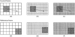
- FIG. 2( b ) shows a current frame and a reference frame.
- the current frame is illustrated on the upper part of the figure with three pel precisions: integer-pel ( FIG. 2( b )( a ) ), half-pel (2-pel) ( FIG. 2( b )( b ) ), and quarter-pel (4-pel) ( FIG. 2( b )( c ) ) precisions.
- the reference frame is illustrated on the lower part of the figure, also with three pel precisions: integer-pel ( FIG. 2( b )( d ) ), half-pel (2-pel) ( FIG.
- FIG. 2( b )( e ) shows that, for a given current block and motion vector, the prediction block pixels are determined with a better accuracy when using a 2-pel precision than when using integer precision, as well as when using a 4-pel precision than when using a 2-pel precision.
- the precision of a motion vector can be represented in different accuracies.
- the 4-pel precision has been introduced in H.264/AVC and it is also used in HEVC.
- the 4-pel precision refers to using a quarter of the distance between pixels (or luma sample positions) as the motion vector precision for motion estimation and MCP.
- fractional accuracy for motion vectors instead of integer accuracy, the residual error is decreased and coding efficiency of video coders is increased.
- the samples of the PB for an inter-coded CB are obtained from those of a corresponding block region in the reference picture, which is at a position displaced by the horizontal and vertical components of the motion vector.
- Fractional sample interpolation may be used to generate the prediction for non-integer sampling positions.
- Interpolation filters are used to help predict the accurate values of pixels. Though higher precision motion vectors take more bits to encode, they can sometimes result in more efficient compression overall, by increasing the quality of the prediction signal.
- fractional-pel values also referred to as “fractional-pel” values
- fractional-pel precisions e.g. quarter-pel precision, half-pel precision
- integer pixel values are interpolated using an interpolation filter. Interpolation may be used for any type of pixel values, that is, for luma sample positions and/or chroma sample positions.
- the number of integer pixel values involved in the interpolation process depends on the number of taps of the interpolation filter.
- Pixel prediction based on motion estimation can therefore be improved by reaching fractional-pel values pointed to by a motion vector having fractional accuracy.
- the interpolation filter specified in H.264/AVC uses various combinations of separable one-dimensional filters according to the fractional sample position.
- the main features of the interpolation filter used in the AVC standard are: 6-taps interpolation filter for obtaining luma samples at half-pel positions, cascade averaging for obtaining luma samples at quarter-pel positions, and bilinear interpolation for chroma samples.
- DCT-IF Discrete Cosine Transformation—Interpolation Filter
- the main features of DCT-IF interpolation filter used in H.265/HEVC standard are: symmetric 8-taps filter for luma samples at half-pel positions, asymmetric 7-taps filter for luma samples at quarter-pel positions, 4-taps filter for chroma samples.
- Filter coefficients for chroma and luma samples in HEVC are shown in Table 1 and Table 2, respectively.
- DCT-IF is efficient, it is not adapted to objects whose speed vary, since it cannot compensate variations in the amount of motion-related blurriness incurred by a camera capture. Furthermore, DCT-IF tries to maximize accuracy, but this may not be a wanted characteristic when interpolating fast-moving objects.
- FIG. 3 is a block schematic diagram of a method of encoding a first image in a plurality of images of input video data according to embodiments of the present subject disclosure.
- the first image may be divided into a plurality of pixel blocks as discussed above, which may or may not be of equal size or of same shape, for purposes of encoding the image through encoding of the blocks, possibly according to a block encoding sequence.
- the block encoding sequence for processing, at the encoder or at the decoder, the blocks of the first image may define a sequence according to which blocks are encoded one after another. Because the blocks of the first image may be encoded at the encoder according to a predetermined processing sequence, the encoded blocks may be decoded at the decoder according to the same processing sequence. For example, a raster scan sequence may scan the blocks of the image starting from the block located at the leftmost upper corner of the first image (represented by a pixel matrix), and progress to the block adjacent to the previously scanned block located to the right of such.
- the pixel blocks of the image may each be any set of pixels of the image, and may be chosen so that the set of blocks forms a partition of the image, that is, each pixel of the image belongs to only one blocks, and there is a one-to-one correspondence between each pixel of the image and a pixel of at least one block.
- each block may correspond, depending on the block, to luma sample values, or to chroma sample values.
- the H.264/MPEG-4 AVC video coding standard uses so-called “macroblocks”, each macroblock comprising a 16 ⁇ 16 block of luma samples, and two corresponding 8 ⁇ 8 blocks of chroma samples for 4:2:0 color sampling.
- the encoding of a current block of the first image using inter prediction encoding typically involves, as discussed above, a reference image in the plurality of images, which reference image was previously encoded according to an image encoding sequence for encoding the images of the plurality of images.
- a motion speed may be determined ( 301 ) for the current block, with respect to a reference block correlated to the current block in the reference image of the plurality of images.
- the motion of the current block may be determined using conventional motion estimation techniques, which will typically determine one or more reference images which contain prediction blocks that are correlated with the current block.
- An interpolation filter may be then determined ( 302 ) based on the motion speed determined for the current block. Details of interpolation filter designs that takes into account a motion speed calculated for a current block are provided hereinafter.
- the interpolation filter adapted to the motion speed may then be used ( 303 ) for calculating fractional pixel values in the reference image as part of a temporal prediction of pixels of the current block based on the prediction block of the reference image, for example as part of a motion estimation of the current block with respect to the prediction block of the reference image.
- different filter coefficients may be derived for each block of an image to be processed for motion interpolation in inter-picture prediction of the block.
- Motion Adaptive Interpolation Filter as provided in the present subject disclosure advantageously gives the ability to improve the interpolation process from static (the same for all motion) to dynamic, hence adapting the interpolation to the speed of the motion in the video.
- the proposed process (that may be referred to as the MAIF technique) advantageously allows the interpolation to be different for slow motion and high-speed motion, therefore it allows the inter prediction to be blurrier when there are large motions and sharper when there is slow motion. This feature addresses among other the problem related to a camera not being able to catch the motion of high-speed objects in a given exposure time.
- the proposed process is indeed beneficial in that it addresses potential limitations of the video capture device that make such device blur out moving objects. Therefore the proposed process advantageously introduces an adaptive interpolation based on a motion estimation performed on an image of a video.
- FIG. 3( b ) illustrates an example of high motion in a video sequence “BasketballPass”.
- FIG. 3( b ) shows a scene captured by a camera, in which the hands of basketball players moving in high speed are blurry due to the camera not being capable to correctly catch all the details.
- the determination of a motion speed value m for the current block may be based on a motion vector calculated for the current block, typically as part of a motion compensation process performed for the current block.
- a motion vector may then be determined for the current block, and the motion speed may be determined based on the motion vector.
- the motion speed may be determined based on a norm of the motion vector.
- 2 ⁇ square root over (
- a motion speed value m for the current block may be determined based on a temporal distance between the first image and the reference image in the input video data.
- the motion speed value may be obtained based on a norm of the motion vector, and a value representing or corresponding to a time difference ⁇ t between the current frame and the reference frame (or, depending on the embodiment, an estimate thereof):
- the proposed interpolation filter may be a Kaiser-windowed Finite Impulse Response (FIR) filter with an adjustment of the bandwidth size based on the motion speed m determined for the current block.
- FIR Finite Impulse Response
- a non-scaled filter impulse response g(i) of an interpolation filter is defined by the following formula, referred to herein as Equation 1:
- g ⁇ ( i ) ( sin ⁇ ⁇ c ⁇ ( ⁇ ⁇ ( i + p ) D ⁇ ( m ) ) * r ⁇ e ⁇ c ⁇ t m ⁇ ( i ) ) ⁇ w ⁇ ( i + p )
- Equation 1 the symbols used in Equation 1 are defined as follows:
- a filter having an impulse response using a cardinal sine function is typically used as a filter having an ideal response in that it removes all frequency components above a given cutoff frequency, without affecting lower frequencies, and with a linear phase response.
- the filter impulse response is a sinc function in the time domain, and its frequency response is a rectangular function. It is a so called “ideal” low-pass filter in the frequency domain, as it passes frequencies below a cutoff frequency, and also cuts frequencies above the cutoff frequency.
- the zero crossing of the first lobe depends on the argument of the sinc function, which in the proposed design corresponding to Formula 1 advantageously depends on m because of D(m).
- a windowing function may advantageously be used in order to reduce the amplitude of frequency components that result from the use of discrete functions instead of continuous functions. Indeed, while the Fourier transform of a continuous cardinal sine function has a rectangular shape in the frequency domain with sharp frequency cut-off, the Fourier transform of a discrete cardinal sine function has a rectangular shape in the frequency domain with side lobes that correspond to noise with respect to the desired rectangular shape. A windowing function may then be used to attenuate such side lobes in the frequency domain.
- any suitable windowing function verifying the above criteria may be used in the design of the filter impulse response.
- the Kaiser window function may advantageously be used, as it adequately attenuates side lobes in the frequency domain.
- real coefficients j and k can take any positive real number, for example 0.9, 1, or 1.1, and 0.01, or 0.001 respectively.
- abs( ⁇ right arrow over (mv) ⁇ ) is based on an absolute value of the component of the motion vector in the direction of the interpolation (e.g. horizontal or vertical), and j and k are two positive real numbers.
- n may be obtained as:
- ⁇ t is an estimate of the time difference between the current frame and the reference frame
- abs( ⁇ right arrow over (mv) ⁇ ) is based on an absolute value of the component of the motion vector in the direction of the interpolation (e.g. horizontal or vertical)
- j and k are two positive real numbers.
- the non-scaled filter impulse response coefficients g(i) may be combined (e.g. summed) to obtain scaled values.
- the coefficients g(i) may be summed in order to obtain the following scale value T:
- the floating-point filter impulse response may then be adjusted using the following formula to provide a DC gain equal to 1:
- the set of h(i) coefficients represents the output of the interpolation filter determination, in that it contains the values of the filter coefficients to be used to interpolate the current block at fractional pixel position p.
- FIG. 4 shows plots of the sinc function
- D(m) is chosen in a way to vary in the same way as m (in other words, as m increases, D(m) increases and vice-versa), that means that for higher motion, the sinc filter will cut off higher frequencies and keep the smaller ones. In other words, it will act as a blurring filter, which is exactly what we want because fast moving objects appear blurry in the video.
- Equation 1 A convolution with a rectangular window was introduced in Equation 1 in order to appropriately simulate the process of capturing the image (frame) by a camera.
- the camera is not capable of capturing a single instant, so instead, what the camera actually does is integrate what it sees in a given period of time depending on shutter speed. It can be represented as a function:
- f(x, y, t) is approximately constant during the whole shutter time.
- an integration for each value of a pixel is performed from the beginning of the shutter time until the end of the shutter time.
- the proposed interpolation filter of Formula 1 advantageously imitates this process via the convolution of the sinc function with a rectangular window.
- FIGS. 5( a ), 5( b ) and 5( c ) The effect of convoluting a sinc function with a rectangular window is illustrated on FIGS. 5( a ), 5( b ) and 5( c ) .
- FIG. 5( a ) shows the plot of a
- the rectangular function of width equal to 1 may be defined as follows:
- the rectangular function of width equal to 3 may be defined as follows:
- FIG. 5( c ) shows respective plots of the convolution of the sinc function of FIG. 5( a ) with the rectangular functions of FIG. 5( b ) , that is, the convolution of the sinc function with a rectangular window function for two different widths of the rectangular window function.
- the resulting filter cuts off higher frequencies and hence blurs out the prediction.
- the filter sharpens the prediction.
- the width w rect of the rectangular window convolved with the sinc function may be chosen in one or more embodiments proportional to m, which advantageously provides a motion adaptive interpolation filter that blurs out/sharpens the prediction whenever appropriate, hence yielding coding gains because of a more efficient inter prediction.
- the present subject disclosure provides different embodiments through which different filters are proposed, each with a transfer function dependent on a motion speed parameter, which may advantageously be used for interpolation during a temporal (e.g. inter) prediction of pixels.
- a motion speed parameter which may advantageously be used for interpolation during a temporal (e.g. inter) prediction of pixels.
- the general behavior of the proposed filters is configurable through the definition of parameters that depend on an estimated motion speed m, such as the D(m) and/or w rect (m) parameters described herein.
- the proposed process further takes into account the GOP (Group of Pictures) structure used as encoding configuration.
- GOP Group of Pictures
- generally sharper interpolation filters have shown better gains for RA (Random Access) configurations, but generally smoother interpolation filters have shown better results for LD (Low Delay) configurations. Therefore one interpolation filter definition might not be suitable for all configurations.
- the proposed method may further comprise the signaling, on an image/frame level, information indicating which interpolation filter definition is used for all blocks of the current image/frame.
- the signaling also allows switching back to DCT-IF if needed, that is, switching back to use of the conventional HEVC interpolation filters.
- DCT-IF is generally blurrier than the proposed method, even for high motion speeds. Therefore, for low delay applications, it may be advantageous to use a blurry filter in order to avoid propagation of prediction error artefacts.
- a window function is a mathematical function that is zero-valued outside of some chosen interval. In typical applications, these functions are non-negative, smooth, “bell-shaped” curves.
- Some window functions such as the Rectangular window, Triangular window, Parzen window, Blackman window, and Hamming window, are known in the field of signal processing.
- the Kaiser window function is defined as:
- I 0 (x) represents the modified 0 th order Bessel function of the first kind
- ⁇ is a window shape tuning parameter that adjusts the trade-off between stop-band attenuation or pass-band ripple and transition bandwidth. This function can be computed using the approximation.
- the Kaiser window may in some embodiments be preferred to other window functions because of its capability to adapt the number of lobes, the width, and the slope of the window on two coefficients:
- an interpolation filter based on the motion speed may be determined by obtaining its transfer function as a product of a cardinal sine function whose argument depends on the motion speed (m), and a window function, preferably a Kaiser window function as discussed above.
- Equation 2 the transfer function g(i) of the interpolation filter is given by the following formula, referred to herein as Equation 2:
- g ⁇ ( i ) sin ⁇ ⁇ c ⁇ ( ⁇ ⁇ ( i + p ) D ⁇ ( m ) ) ⁇ w ⁇ ( i + p )
- Equation 2 the symbols used in Equation 2 are defined as follows:
- sinc is the cardinal sine function, which may be defined as:
- D(m) is a low-pass factor of the sinc function which depends on the motion speed value m;
- p is a fractional phase offset, which indicates a fractional pixel position
- w is a windowing function that is symmetric around zero and has a zero value outside the range of plus or minus L (2*L being the number of taps of the filter) and nonzero within that range, except possibly at the extreme boundaries.
- real coefficients j and k can take any positive real number, for example 0.9, 1, or 1.1, and 0.01, or 0.001 respectively.
- D(m) may be obtained as:
- ⁇ t is an estimate of the time difference between the current frame and the reference frame
- abs( ⁇ right arrow over (mv) ⁇ ) is based on an absolute value of the component of the motion vector in the direction of the interpolation (e.g. horizontal or vertical)
- j and k are two positive real numbers.
- Equation 2 may be seen as a particular case of Equation 1 above, in which rect is a Dirac delta function.
- FIG. 7( a ) illustrates the filtering of input video data by a filter corresponding to the first design, to generate output filtered data.
- the input video data may comprise a sequence of integer pixel values (corresponding to luma sample positions and/or chroma sample positions), and the output filtered data comprise fractional pixel values obtained from the interpolated integer pixel values.
- a D(m) parameter may also be provided in embodiments as control parameter for the configuration of the filter.
- an interpolation filter based on the motion speed may be determined by obtaining its transfer function as a product of a cardinal sine function whose argument does not depend on the motion speed (m) convolved with a rectangular window function whose width w rect (m) depends on m, and a window function, preferably a Kaiser window function as discussed above.
- Equation 3 the transfer function g(i) of the interpolation filter is given by the following formula, referred to herein as Equation 3:
- g ⁇ ( i ) ( sin ⁇ ⁇ c ⁇ ( ⁇ ⁇ ( i + p ) D ) * r ⁇ e ⁇ c ⁇ t m ⁇ ( i ) ) ⁇ w ⁇ ( i + p )
- Equation 3 The symbols used in Equation 3 are defined in the same manner as corresponding symbols defined for Equation 1.
- rect m (i) is a rectangular window function, with a width w rect (m) which also depends on m, designed to control motion blur by convoluting with the cardinal sine function.
- a suitable rectangular window function can be defined as follows:
- w is a windowing function that is symmetric around zero and has a zero value outside the range of plus or minus L (2*L being the number of taps of the filter) and nonzero within that range, except possibly at the extreme boundaries.
- the coefficient l is a real positive number which may vary based on video camera configuration.
- values that can be used for the coefficient l include 0.025, 0.05 and 0.1.
- w rect (m) may be obtained as:
- w r ⁇ e ⁇ c ⁇ t ⁇ ( m ) l ⁇ abs ⁇ ⁇ ( mv ⁇ ) ⁇ ⁇ t , where ⁇ t is an estimate of the time difference between the current frame and the reference frame, abs( ⁇ right arrow over (mv) ⁇ ) is based on the absolute value of the component of the motion vector in the direction of the interpolation, and l is a positive real number, which may be chosen based on a configuration of the video camera used for capturing the video content (e.g. 0.025, 0.05, or 0.1).
- FIG. 7( b ) illustrates the filtering of input video data by a filter corresponding to the second design, to generate output filtered data.
- the input video data may comprise a sequence of integer pixel values (corresponding to luma sample positions and/or chroma sample positions), and the output filtered data comprise fractional pixel values obtained from the interpolated integer pixel values.
- D and w rect (m) or, depending on the embodiment, D and m parameters may also be provided in embodiments as control parameter for the configuration of the filter.
- an interpolation filter based on the motion speed may be determined by obtaining its transfer function as a product of a cardinal sine function whose argument depends on the motion speed (m) convolved with a rectangular window function whose width w rect (m) also depends on m, and a window function, preferably a Kaiser window function as discussed above.
- Equation 4 the transfer function g(i) of the interpolation filter is given by the following formula, referred to herein as Equation 4:
- g ⁇ ( i ) ( sin ⁇ ⁇ c ⁇ ( ⁇ ⁇ ( i + p ) D ⁇ ( m ) ) * r ⁇ e ⁇ c ⁇ t m ⁇ ( i ) ) ⁇ w ⁇ ( i + p )
- Equation 4 The symbols used in Equation 4 are defined in the same manner as corresponding symbols defined for Equation 1.
- abs( ⁇ right arrow over (mv) ⁇ ) is a value of a norm of the motion vector (e.g. abs( ⁇ right arrow over (mv) ⁇ ) corresponds to the absolute value of the component of the motion vector in the direction of the interpolation (e.g. horizontal or vertical)), and where real coefficients j and k can take any positive real value, for example 0.9, 1, or 1.1, and 0.01, or 0.001 respectively.
- D(m) may be obtained as:
- ⁇ t is an estimate of the time difference between the current frame and the reference frame
- abs( ⁇ right arrow over (mv) ⁇ ) is based on the absolute value of the component of the motion vector in the direction of the interpolation
- j and k are two positive real numbers.
- the selection of a D(m) parameter definition may be signaled at the frame level and used for all blocks of the frame.
- abs( ⁇ right arrow over (mv) ⁇ ) is based on the absolute value of the component of the motion vector in the direction of the interpolation (e.g. horizontal or vertical), and the coefficient l is a real positive number which can vary based on video camera configuration.
- the values of the coefficient l which can be used for example are 0.025, 0.05 or 0.1.
- FIG. 7( c ) illustrates the filtering of input video data by a filter corresponding to the third design, to generate output filtered data.
- the input video data may comprise a sequence of integer pixel values (corresponding to luma sample positions and/or chroma sample positions), and the output filtered data comprise fractional pixel values obtained from the interpolated integer pixel values.
- D(m) and w rect (m) parameters or, depending on the embodiment, a m parameter may also be provided in embodiments as control parameter for the configuration of the filter.
- an interpolation filter based on the motion speed may be determined by obtaining its transfer function by multiplying a sinc function with a window function (preferably a Kaiser window function).
- a window function preferably a Kaiser window function
- the sinc function may be convoluted in the time domain with a (e.g. rectangular) window function, whose length may be chosen dependent on a motion speed for the current block, for example through being proportional to a norm of a motion vector calculated for the current block.
- the transfer function g(i) of the proposed motion adaptive interpolation filter may be defined as:
- g ⁇ ( i ) ( sin ⁇ ⁇ c ⁇ ( ⁇ ⁇ ( i + p ) D ⁇ ( m ) ) * r ⁇ e ⁇ c ⁇ t m ⁇ ( i ) ) ⁇ w ⁇ ( i + p )
- abs( ⁇ right arrow over (mv) ⁇ ) is based on the absolute value of the component of the motion vector in the direction of the interpolation (e.g. horizontal or vertical), and j and k may be any positive real number.
- Equation 5 The symbols used in Equation 5 are defined in the same manner as corresponding symbols defined for Equation 1.
- FIG. 7( d ) illustrates the filtering of input video data by a filter corresponding to the fourth design, to generate output filtered data.
- the input video data may comprise a sequence of integer pixel values (corresponding to luma sample positions and/or chroma sample positions), and the output filtered data comprise fractional pixel values obtained from the interpolated integer pixel values.
- a w rect (m) parameter or, depending on the embodiment, an m parameter may also be provided in embodiments as control parameter for the configuration of the filter.
- abs( ⁇ right arrow over (mv) ⁇ ) corresponds to, as discussed above, an absolute value of the component of the motion vector in the direction of the interpolation (e.g. horizontal or vertical), and the coefficient l is a real value which can vary on camera configuration.
- the size of the window as dependent on the motion vector advantageously represents by how much an object moved between the opening and the closing of the shutter.
- This window function is symmetric around 0 and does not have zero values for bandwidth values ⁇ 4 and 4, as can be seen on the impulse response in the time domain illustrated on FIG. 8( a ) .
- interpolation is typically performed separately for horizontal and vertical values.
- the choice of different filter coefficients for different motion speeds may therefore advantageously also be done separately.
- pixel values should preferably be interpolated smoother in the horizontal direction because the x-value is greatly larger than the y-value of the motion vector.
- pixel values should preferably be interpolated with a sharper filter since the y-value is smaller.
- signaling at the frame level is used to switch between different interpolation filter definitions.
- a frame-level signaling may be used to switch between a MAIF interpolation filter, e.g. according to the above-described first, second, third or fourth design and DCT-IF filtering used in HEVC.
- DCT-IF has indeed proven to be more efficient for low delay encoding configurations.
- the MAIF interpolation filters of the present subject disclosure are much more efficient.
- FIG. 8( b ) illustrates the respective transfer functions in the time domain of the fourth design MAIF filter, using a Kaiser window as shown on FIG. 7( a ) , for different value of abs(mv).
- the transfer function width increases in time domain, which means that it gets narrower in the frequency domain.
- the filter cuts off more frequencies, hence the blur in the resulting interpolation.
- the proposed method may be used for the processing, for purposes of encoding or compression, or decoding or decompression, of input video data.
- Information and signals described herein can be represented using any of a variety of different technologies and techniques.
- data, instructions, commands, information, signals, bits, symbols, and chips can be represented by voltages, currents, electromagnetic waves, magnetic fields or particles, optical fields or particles, or any combination thereof.
Landscapes
- Engineering & Computer Science (AREA)
- Multimedia (AREA)
- Signal Processing (AREA)
- Compression Or Coding Systems Of Tv Signals (AREA)
Abstract
Description
D(m)=j+k*abs({right arrow over (mv)})
| TABLE 1 |
| Luma interpolation filter coefficients for DCTIF |
| Frac | Coefficients |
| 0 | {0, 0, 0, 64, 0, 0, 0, 0} |
| 1 | {−1, 4, −10, 58, 18, −5, 1} |
| 2 | {−1, 4, −11, 40, 40, −11, 4, −1} |
| 3 | {1, −5, 18, 58, −10, 4, −1} |
| TABLE 2 |
| Chroma interpolation filter coefficients for DCTIF |
| Frac | Coefficients |
| 0 | {0, 64, 0, 0} |
| 1 | {−2, 58, 10, −2} |
| 2 | {−4, 54, 16, −2} |
| 3 | {−6, 46, 28, −4} |
| 4 | {−4, 36, 36, −4} |
| 5 | {−4, 28, 46, −6} |
| 6 | {−2, 16, 54, −4} |
| 7 | {−2, 10, 58, −2} |
Indeed it may be considered that using both of these parameters in the determination of a motion speed value provides a more accurate representation of the motion speed.
f(i)*g(i)=Σm=−∞ ∞ f(m)·g(i−m),
-
- Sinc is the cardinal sine function, which may be defined as:
-
- D(m) is a low-pass factor of the sinc function which depends on the motion speed value m;
- p is a fractional phase offset, which indicates a fractional pixel position;
- rectm(i) is a rectangular window function, with a width wrect(m) which also depends on m, designed to control motion blur by convoluting with the cardinal sine function. A suitable rectangular window function can be defined as follows:
-
- w is a windowing function that is symmetric around zero and has a zero value outside the range of plus or minus L (2*L being the number of taps of the filter) and nonzero within that range, except possibly at the extreme boundaries.
D(m)=j+k·m
in the time domain for three different values of D (D=1, D=1,5, and D=2). Each argument i+p corresponds to an integer argument i (i∈{−4, −3, −2, −1, 0, 1, 2, 3, 4}) to which a fractional value p (p∈{0, 0.25, 0.5, 0.75}) is added. As the argument of the sinc function increases, the width of the first lobe decreases. Therefore, since the argument of sinc function used in the proposed interpolation filter is inversely proportional to D(m), the width of sinc increases as D(m) increases, and the width of sinc decreases as D(m) decreases, as shown in
-
- x, y represents a position of a pixel in an image;
- F(x, y) represents the values of pixels after integration;
- f(x, y, t) represents the integrable function of what the camera sees; and
- Δt designates a period of time depending on the shutter speed.
function, each argument i+p corresponding to an integer argument i (i∈{−4, −3, −2, −1, 0, 1, 2, 3, 4}) to which a fractional value p (p∈{0, 0.25, 0.5, 0.75}) is added.
f(i)*g(i)=Σm=−∞ ∞ f(m)·g(i−m),
D(m)=j+k·m
f(i)*g(i)=Σm=−∞ ∞ f(m)·g(i−m),
w rect(m)=m·l
where Δt is an estimate of the time difference between the current frame and the reference frame, abs({right arrow over (mv)}) is based on the absolute value of the component of the motion vector in the direction of the interpolation, and l is a positive real number, which may be chosen based on a configuration of the video camera used for capturing the video content (e.g. 0.025, 0.05, or 0.1).
D(m)=j+k·abs({right arrow over (mv)})
D(m)=1.0+0.01*abs({right arrow over (mv)})
D(m)=1.1+0.01*abs({right arrow over (mv)}),
w rect=abs({right arrow over (mv)})*l
D(m)=j+k·abs({right arrow over (mv)})
g(i)=(sinc(π(i+p))*rectm(i))·w(i+p)
w rect=abs({right arrow over (mv)})*l
Claims (20)
D(m)=j+k·abs({right arrow over (mv)})
D(m)=j+k·abs({right arrow over (mv)})
w rect =abs({right arrow over (mv)})·l
D(m)=j+k·abs({right arrow over (mv)})
D(m)=j+k·abs({right arrow over (mv)})
D(m)=j+k·abs({right arrow over (mv)})
D(m)=j+k·abs({right arrow over (mv)})
Applications Claiming Priority (3)
| Application Number | Priority Date | Filing Date | Title |
|---|---|---|---|
| EP19305208 | 2019-02-21 | ||
| EP19305208.1 | 2019-02-21 | ||
| EP19305208.1A EP3700210A1 (en) | 2019-02-21 | 2019-02-21 | Method and apparatus for image encoding |
Publications (2)
| Publication Number | Publication Date |
|---|---|
| US20200275097A1 US20200275097A1 (en) | 2020-08-27 |
| US11218696B2 true US11218696B2 (en) | 2022-01-04 |
Family
ID=65766922
Family Applications (1)
| Application Number | Title | Priority Date | Filing Date |
|---|---|---|---|
| US16/797,300 Active US11218696B2 (en) | 2019-02-21 | 2020-02-21 | Method for image encoding and apparatus for implementing the same using interpolation filter based on motion speed |
Country Status (2)
| Country | Link |
|---|---|
| US (1) | US11218696B2 (en) |
| EP (1) | EP3700210A1 (en) |
Cited By (3)
| Publication number | Priority date | Publication date | Assignee | Title |
|---|---|---|---|---|
| US20220038748A1 (en) * | 2020-07-30 | 2022-02-03 | Ateme | Method for image processing and apparatus for implementing the same |
| US20230353766A1 (en) * | 2020-12-18 | 2023-11-02 | Huawei Technologies Co., Ltd. | Method and apparatus for encoding a picture and decoding a bitstream using a neural network |
| US20250240413A1 (en) * | 2022-04-21 | 2025-07-24 | Guangdong Oppo Mobile Telecommunications Corp., Ltd. | Reference picture resampling for video coding |
Families Citing this family (2)
| Publication number | Priority date | Publication date | Assignee | Title |
|---|---|---|---|---|
| CN112770015B (en) * | 2020-12-29 | 2022-09-13 | 紫光展锐(重庆)科技有限公司 | Data processing method and related device |
| US20240223776A1 (en) * | 2023-01-03 | 2024-07-04 | Alibaba (China) Co., Ltd. | Intra template matching prediction mode for motion prediction |
Citations (10)
| Publication number | Priority date | Publication date | Assignee | Title |
|---|---|---|---|---|
| US6728317B1 (en) | 1996-01-30 | 2004-04-27 | Dolby Laboratories Licensing Corporation | Moving image compression quality enhancement using displacement filters with negative lobes |
| US20040228410A1 (en) | 2003-05-12 | 2004-11-18 | Eric Ameres | Video compression method |
| US7266150B2 (en) | 2001-07-11 | 2007-09-04 | Dolby Laboratories, Inc. | Interpolation of video compression frames |
| US20080247462A1 (en) | 2007-04-03 | 2008-10-09 | Gary Demos | Flowfield motion compensation for video compression |
| US20130182770A1 (en) | 2010-11-08 | 2013-07-18 | Sony Corporation | Image processing device, and image processing method |
| US20140314154A1 (en) | 2011-11-24 | 2014-10-23 | Nec Corporation | Video encoding device, video encoding method, and program |
| US8897360B2 (en) | 2009-01-28 | 2014-11-25 | Samsung Electronics Co., Ltd. | Method and apparatus for encoding and decoding images by adaptively using an interpolation filter |
| US9319711B2 (en) | 2011-07-01 | 2016-04-19 | Google Technology Holdings LLC | Joint sub-pixel interpolation filter for temporal prediction |
| EP3306934A1 (en) | 2015-07-03 | 2018-04-11 | Huawei Technologies Co., Ltd. | Image prediction method and related device |
| US20190045193A1 (en) * | 2018-06-29 | 2019-02-07 | Intel Corporation | Region-based motion estimation and modeling for accurate region-based motion compensation for efficient video processing or coding |
-
2019
- 2019-02-21 EP EP19305208.1A patent/EP3700210A1/en not_active Ceased
-
2020
- 2020-02-21 US US16/797,300 patent/US11218696B2/en active Active
Patent Citations (12)
| Publication number | Priority date | Publication date | Assignee | Title |
|---|---|---|---|---|
| US6728317B1 (en) | 1996-01-30 | 2004-04-27 | Dolby Laboratories Licensing Corporation | Moving image compression quality enhancement using displacement filters with negative lobes |
| US7266150B2 (en) | 2001-07-11 | 2007-09-04 | Dolby Laboratories, Inc. | Interpolation of video compression frames |
| US20040228410A1 (en) | 2003-05-12 | 2004-11-18 | Eric Ameres | Video compression method |
| US8824553B2 (en) * | 2003-05-12 | 2014-09-02 | Google Inc. | Video compression method |
| US20080247462A1 (en) | 2007-04-03 | 2008-10-09 | Gary Demos | Flowfield motion compensation for video compression |
| US8160149B2 (en) * | 2007-04-03 | 2012-04-17 | Gary Demos | Flowfield motion compensation for video compression |
| US8897360B2 (en) | 2009-01-28 | 2014-11-25 | Samsung Electronics Co., Ltd. | Method and apparatus for encoding and decoding images by adaptively using an interpolation filter |
| US20130182770A1 (en) | 2010-11-08 | 2013-07-18 | Sony Corporation | Image processing device, and image processing method |
| US9319711B2 (en) | 2011-07-01 | 2016-04-19 | Google Technology Holdings LLC | Joint sub-pixel interpolation filter for temporal prediction |
| US20140314154A1 (en) | 2011-11-24 | 2014-10-23 | Nec Corporation | Video encoding device, video encoding method, and program |
| EP3306934A1 (en) | 2015-07-03 | 2018-04-11 | Huawei Technologies Co., Ltd. | Image prediction method and related device |
| US20190045193A1 (en) * | 2018-06-29 | 2019-02-07 | Intel Corporation | Region-based motion estimation and modeling for accurate region-based motion compensation for efficient video processing or coding |
Non-Patent Citations (18)
| Title |
|---|
| Bjontegaard, "Calculation of Average PSNR Differences between RD-curves," Document VCEG-M33, ITU-T Video Coding Experts Group, 13th Meeting, Austin, TX, US, Apr. 2001, pp. 1-4. |
| Boyce et al., "JVET common test conditions and software reference configurations," Document JVET-J1010-v1, JVET of ITU-T SG16 WP3 and ISO/IEC JTC1/SC29/WG11, 10th Meeting, San Diego, CA, US, Apr. 2018, pp. 1-6. |
| Bross et al., "High Efficiency Video Coding (HEVC) text specification draft 7," Document JCTVC-11003, JCT-VC of ITU-T SG16 WP3 and ISO/IEC JTC1/SC29/WG11, 9th Meeting, Geneva, CH, Apr. 27-May 7, 2012, 280 pages. |
| Bross et al., "Versatile Video Coding (Draft 2)," Document JVET-K1001-v6, JVET of ITU-T SG16 WP3 and ISO/IEC JTC1/SC29/WG11, 11th Meeting, Ljubljana, SI, Jul. 2018, 141 pages. |
| Chen et al., "Algorithm Description for Versatile Video Coding and Test Model 1 (VTM 1)," Document JVET-J1002-v2, JVET of ITU-T SG16 WP3 and ISO/IEC JTC1/SC29/WG11, 10th Meeting, San Diego, CA, US, Apr. 2018, pp. 1-10. |
| Kim et al., "A Fast Fractional-Pel Motion Estimation using 4-Tap Chroma Interpolation Filter for HEVC Encoder," Advanced Science and Technology Letters, vol. 146 (FGCN 2017), 2017, pp. 23-29. |
| Lv et al., "A Resolution-adaptive Interpolation Filter for Video Codec," 2014 IEEE International Symposium on Circuits and Systems (ISCAS), Melbourne, AU, 2014, pp. 542-545. |
| Moghe et al., "Performance Analysis of N-tap Interpolation Filter in H.265/HEVC (High Efficiency Video Coding)," International Journal of Computer Science and Network, vol. 5(6), Dec. 2016, pp. 869-872. |
| Nielsen Holdings PLC, "The Nielsen Total Audience Report," Nielsen Holdings, New York, NY, US, 2018, 32 pages. |
| Search Report issued in related application EP 19305208.1, dated Jul. 10, 2019, 11 pages. |
| Sullivan, "Color format downconversion for test sequence generation," Document JVT-I018, JVT of ISO/IEC MPEG & ITU-T VCEG, 9th Meeting, San Diego, CA, US, Sep. 2003, pp. 1-10. |
| Ugur et al., "Motion Compensated Prediction and Interpolation Filter Design in H.265/HEVC," IEEE Journal of Selected Topics in Signal Processing, vol. 7(6), Dec. 2013, pp. 946-956. |
| Wedi et al., "Motion- and Aliasing-Compensated Prediction for Hybrid Video Coding," IEEE Transactions on Circuits and Systems for Video Technology, vol. 13(7), Jul. 2003, pp. 577-586. |
| Wedi, "Adaptive Interpolation Filter for Motion Compensated Prediction," Proceedings IEEE International Conference on Image Processing, Rochester, NY, US, IEEE, Sep. 2002, pp. II-509-II-512. |
| Wedi, "Adaptive Interpolation Filters and High-Resolution Displacements for Video Coding," IEEE Transactions on Circuits and Systems for Video Technology, vol. 16(4), Apr. 2006, pp. 484-491. |
| Woods, "Improved MC-EZBC with Quarter-pixel Motion Vectors," 60 MPEG Meeting; May 6-10, 2002, Fairfax, VA, US, Motion Picture Expert Group ISO/IEC JTC1/SC29/WG11, No. M8366, May 1, 2002, 16 pages. |
| Yan et al., "A Convolutional Neural Network Approach for Half-Pel Interpolation in Video Coding," 2017 IEEE International Symposium on Circuits and Systems (ISCAS), Baltimore, MD, US, 2017, 4 pages. |
| Yoo et al., "Video resampling algorithm for simultaneous deinterlacing and image upscaling with reduced jagged edge artifacts", EURASIP Journal on Advances in Signal Processing, 2013 (1):188, Dec. 1, 2013, Springer, New York, NY, US, 24 pages. |
Cited By (4)
| Publication number | Priority date | Publication date | Assignee | Title |
|---|---|---|---|---|
| US20220038748A1 (en) * | 2020-07-30 | 2022-02-03 | Ateme | Method for image processing and apparatus for implementing the same |
| US11700397B2 (en) * | 2020-07-30 | 2023-07-11 | Ateme | Method for image processing and apparatus for implementing the same |
| US20230353766A1 (en) * | 2020-12-18 | 2023-11-02 | Huawei Technologies Co., Ltd. | Method and apparatus for encoding a picture and decoding a bitstream using a neural network |
| US20250240413A1 (en) * | 2022-04-21 | 2025-07-24 | Guangdong Oppo Mobile Telecommunications Corp., Ltd. | Reference picture resampling for video coding |
Also Published As
| Publication number | Publication date |
|---|---|
| US20200275097A1 (en) | 2020-08-27 |
| EP3700210A1 (en) | 2020-08-26 |
Similar Documents
| Publication | Publication Date | Title |
|---|---|---|
| US11218696B2 (en) | Method for image encoding and apparatus for implementing the same using interpolation filter based on motion speed | |
| CN106105201B (en) | Deblocking filtering using pixel distance | |
| JP7692096B2 (en) | Corresponding methods of boundary strength derivation for the encoder, decoder, and deblocking filter | |
| US11800097B2 (en) | Method for image processing and apparatus for implementing the same | |
| JP7250917B2 (en) | Method and Apparatus for Intra Prediction Using Interpolating Filters | |
| US20150055705A1 (en) | Image encoding/decoding apparatus and method | |
| US11032542B2 (en) | Method and a device for image encoding and decoding | |
| CN113728629A (en) | Motion vector derivation in video coding | |
| CN113785573A (en) | Encoders, Decoders and Corresponding Methods Using Adaptive Loop Filters | |
| JP7351908B2 (en) | Encoder, decoder, and corresponding method of deblocking filter adaptation | |
| JP2025111512A (en) | Device and method for intra-prediction | |
| CN113243106B (en) | Apparatus and method for intra prediction of prediction block of video image | |
| TWI848969B (en) | Deblocking filter for video coding and processing | |
| CN113170119A (en) | Method and apparatus for interpolation filtering for predictive coding | |
| US20210289202A1 (en) | Intra prediction method and apparatus for performing adaptive filtering on reference pixel | |
| CN119452644A (en) | Method and apparatus for chroma motion compensation using adaptive cross-component filtering | |
| EP4487225A2 (en) | Integerization for interpolation filter design in video coding | |
| Saldanha et al. | Versatile Video Coding (VVC) | |
| Rosário Lucas et al. | Prediction techniques for image and video coding | |
| US12184846B2 (en) | Intra prediction method and apparatus for performing adaptive filtering on reference pixel | |
| US20250240413A1 (en) | Reference picture resampling for video coding | |
| KR20110087871A (en) | Method and device for image interpolation with quarter pixel resolution using intra mode | |
| CN120642330A (en) | Method and apparatus for adaptive motion compensation filtering | |
| CN120958798A (en) | Methods and apparatus for adaptive motion compensation filtering | |
| CN120513625A (en) | Method and apparatus for adaptive motion compensation filtering |
Legal Events
| Date | Code | Title | Description |
|---|---|---|---|
| FEPP | Fee payment procedure |
Free format text: ENTITY STATUS SET TO UNDISCOUNTED (ORIGINAL EVENT CODE: BIG.); ENTITY STATUS OF PATENT OWNER: LARGE ENTITY |
|
| AS | Assignment |
Owner name: ATEME, FRANCE Free format text: ASSIGNMENT OF ASSIGNORS INTEREST;ASSIGNORS:DOROVIC, KATARINA;MORA, ELIE;MONNIER, MATHIEU;SIGNING DATES FROM 20200608 TO 20200707;REEL/FRAME:054040/0308 |
|
| STPP | Information on status: patent application and granting procedure in general |
Free format text: NON FINAL ACTION MAILED |
|
| STPP | Information on status: patent application and granting procedure in general |
Free format text: RESPONSE TO NON-FINAL OFFICE ACTION ENTERED AND FORWARDED TO EXAMINER |
|
| STPP | Information on status: patent application and granting procedure in general |
Free format text: FINAL REJECTION MAILED |
|
| STPP | Information on status: patent application and granting procedure in general |
Free format text: DOCKETED NEW CASE - READY FOR EXAMINATION |
|
| STPP | Information on status: patent application and granting procedure in general |
Free format text: NOTICE OF ALLOWANCE MAILED -- APPLICATION RECEIVED IN OFFICE OF PUBLICATIONS |
|
| STPP | Information on status: patent application and granting procedure in general |
Free format text: PUBLICATIONS -- ISSUE FEE PAYMENT RECEIVED |
|
| STPP | Information on status: patent application and granting procedure in general |
Free format text: PUBLICATIONS -- ISSUE FEE PAYMENT VERIFIED |
|
| STCF | Information on status: patent grant |
Free format text: PATENTED CASE |
|
| MAFP | Maintenance fee payment |
Free format text: PAYMENT OF MAINTENANCE FEE, 4TH YEAR, LARGE ENTITY (ORIGINAL EVENT CODE: M1551); ENTITY STATUS OF PATENT OWNER: LARGE ENTITY Year of fee payment: 4 |