US1121663A - Animal-trap. - Google Patents
Animal-trap. Download PDFInfo
- Publication number
- US1121663A US1121663A US84847714A US1914848477A US1121663A US 1121663 A US1121663 A US 1121663A US 84847714 A US84847714 A US 84847714A US 1914848477 A US1914848477 A US 1914848477A US 1121663 A US1121663 A US 1121663A
- Authority
- US
- United States
- Prior art keywords
- jaws
- trap
- animal
- base plate
- jaw
- Prior art date
- Legal status (The legal status is an assumption and is not a legal conclusion. Google has not performed a legal analysis and makes no representation as to the accuracy of the status listed.)
- Expired - Lifetime
Links
Images
Classifications
-
- A—HUMAN NECESSITIES
- A01—AGRICULTURE; FORESTRY; ANIMAL HUSBANDRY; HUNTING; TRAPPING; FISHING
- A01M—CATCHING, TRAPPING OR SCARING OF ANIMALS; APPARATUS FOR THE DESTRUCTION OF NOXIOUS ANIMALS OR NOXIOUS PLANTS
- A01M23/00—Traps for animals
- A01M23/24—Spring traps, e.g. jaw or like spring traps
- A01M23/26—Spring traps, e.g. jaw or like spring traps of the double-jaw or pincer type
Definitions
- This invention relates to new and useful .improvements intraps,"and particularly to that'class of traps which are provided with spring actuated jaws.
- 'An object of this invention is the provision of a trap having spring actuated jaws, each of the'jaws being provided with a supplemental flexible j awwhich when the jaws are in closed position are disposed inwardly of the main jaws to engage'the foot of the animal and slack the speed of the outside jaws, to prevent "the same from breaking the leg.
- a further object'of this invention is the provision of a trap which includes spring actuated toothed jaws, to which flexible steel spring wire jaws are connected, the flexiblewire jaws being disposed below and inwardly of the toothed jaws when the same are in closed position,,to prevent the animal from gnawing the leg below the main jaws of the trap.
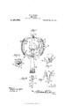
- Fig. 3 is asectional view on the line 3'3 of Fig. 1;
- Fig. 4 is an end view of the jaws in closed position showing the same removed from the base plate; and
- Fig. 5 isj an end view of the jaws in partially open position,
- the numeral l'designate s the elongated base plate of the trap, the base plate having a pan plate 2 projecting'laterally .therefrom intermediate of its ends.
- Angular openings 3 are formedin the opposite ends of the base of the jaw holders are angular reference being had to the accom-,
- Each of the jaw holders 4 is provided in its upper face with an elongated groove 8, the grooves extending at right angles to the'longitudinal plane of the base plate, and passing through the walls in the groove of the jaw holder is a pair of pins 9 upon which are pivotally mounted theends of a'pair of substantiallv U-shaped jaws 10.
- Each of the jaws 10 is. provided in its inner face with a longitudinal series of transversely extending teeth 11,
- a spring 12 is provided, the spring being of the usual U- shaped construction and being provided with an enlarged apertured head 13 atone end, the .head being adapted for engage ment over one of the jaw holders 4 beneath the jaws, so that the upper leg of the spring upon movingupwardly owing to the tension of the metal composing the spring will close the jaws and hold the same tightly against each other.
- a device of the character described comprising a base plate; sprmg actuated main jaws pivotally connected tosaid base plate, means for holding thetjaws in open position against the tension of the spring, and yielding supplemental jaws connected to the first mentioned jaws and disposed slightly inward thereof, but out of alinement therewith.
- a device of the character described comprising a base plate, spring pressed aws pivotally connected to said'base plate, flexi- Copies of this patent may be obtained for five cents each, b yvaddressing the ble supplemental jaws connected at their op- 1 posite ends to the first mentioned jaws, the intermediate portions of said supplemental jaws being disposed inwardly and downwardly of the first mentioned jaws, means for holding said jaws in open position against the tension of the spring, and means for releasing the last mentioned means. 3.
- a device of the character described comprising a base plate, a plate extending laterally from the base plate intermediate oilits ends, jaws pivotally connected at their opposite ends to said base plate, flexible supplemental jaws connected at their voppo- -site ends to the first mentioned jaws, said supplementaljaws being disposed inwardly and downwardly of the first mentioned jaws intermediate of their ends,'a trigger piv otally connected to the-outer extremity of l the laterally extending plate said trigger being adapted to engage oyer oneof said jaws to retain the same in open position against the tension of the spring, a trigger bar pivo'tallyv connected' to the laterally extending (plate for engagement. at one end with the trigger to lock the aws in open position, and a bait pan carried'by the op.-
- a movably mounted jawfand a resiliently yielding member extending parallel to but out of alinemcnt with the jaw and disposed inward thereof.
- a base plate spring actuated oppositely disposed jaws pivotally connect I ed to thebase plate, a trigger mechanism for holding the aws in open posit on, and resiliently yielding members mounted upon-H and movable with the jaws and disposed each in-a plane in advance of the inner face of each jaw and out of alinement therewith;
Description
P. B. PRANTE.
ANIMAL TRAP.
APPLIOATION'IILBD JULY 1, 1914.
1,121,663 Patented Dec. 22, 1914. M
I i UNKTE menses.
emits PATENT ornicn FREDERICK B. FBANTE, OF PACIFIC BEACH, WASHINGTON, ASSIGNOR OF, oNE l-IALF TO MICHAEL SPINJNER, OF
GATE, WASHINGTON.
ANIMAL-TRAP.
To all whom it may concern 1 Be it known that I, F EDERICK B- PRANTE, citizen of the United States, residing at Pacific Beach, in the county of Chehalis and State of Washington, have invented certain new and useful Improvements in Animal- Traps, of which the following is a specification, panyingdrawings.
This invention relates to new and useful .improvements intraps,"and particularly to that'class of traps which are provided with spring actuated jaws.
'An object of this invention is the provision of a trap having spring actuated jaws, each of the'jaws being provided with a supplemental flexible j awwhich when the jaws are in closed position are disposed inwardly of the main jaws to engage'the foot of the animal and slack the speed of the outside jaws, to prevent "the same from breaking the leg. I
A further object'of this invention is the provision of a trap which includes spring actuated toothed jaws, to which flexible steel spring wire jaws are connected, the flexiblewire jaws being disposed below and inwardly of the toothed jaws when the same are in closed position,,to prevent the animal from gnawing the leg below the main jaws of the trap. Y
WVith these and other objects in view, my
invention consists in the novel construction,
of one end of the base plate showing one end.
.of the. jaws pivotally connected thereto; Fig. 3 is asectional view on the line 3'3 of Fig. 1; Fig. 4: is an end view of the jaws in closed position showing the same removed from the base plate; and Fig. 5isj an end view of the jaws in partially open position,
showing. the same removed from the base plate.
Referring more particularly to the drawing, the numeral l'designate's the elongated base plate of the trap, the base plate having a pan plate 2 projecting'laterally .therefrom intermediate of its ends. Angular openings 3 are formedin the opposite ends of the base of the jaw holders are angular reference being had to the accom-,
y turning relatively to the base plate,
holders are secured to and arrangement of parts, to
1 is a top plan vlew of im-' Specificationof Letters Patent. Patented D 22 1914;; Application filed July 1, 1914. Serial No. 848,477. I
1 plate, and jaw holders 4 which are provided with reduced depending extensions 5 areadapted for connection to the opposite ends of the base plate. The-reduced extensions 5 as at 6 atthe juncture of, the extensions with the body portion of the holder, the angular portion 6 being engaged in the angular openings 3 in the plate to prevent the jaw holders from r and the lower extremi tiesof the extensions 5 which,
projectbelow thebase plate are threaded for the reception of nuts 7 whereby the jaw the plate 1. Each of the jaw holders 4 is provided in its upper face with an elongated groove 8, the grooves extending at right angles to the'longitudinal plane of the base plate, and passing through the walls in the groove of the jaw holder is a pair of pins 9 upon which are pivotally mounted theends of a'pair of substantiallv U-shaped jaws 10. Each of the jaws 10 is. provided in its inner face with a longitudinal series of transversely extending teeth 11,
'theteeth of one jaw being disposed between the teeth of the other jaw, so that the jaws when closed against the leg of'an animal, will kink the hide, thus preventing the animal from pulling itsleg out of the trap and also preventing the animal from twisting its leg and pulling the fur out, and preventing the pelt from becoming damaged. To close, the jaws 10, a spring 12 is provided, the spring being of the usual U- shaped construction and being provided with an enlarged apertured head 13 atone end, the .head being adapted for engage ment over one of the jaw holders 4 beneath the jaws, so that the upper leg of the spring upon movingupwardly owing to the tension of the metal composing the spring will close the jaws and hold the same tightly against each other. Pivotally connected adjacent one end to theupperend of a stem 14: pro-, jecting from the pan plate 2, is a triggerbar,
15 to the longer or inner end of which is secured a bait pan 16, and pivotally connected to the outer upturned end 17 of the plate 2 V is the outer end of a trigger 18, the trigger 18vbeing adapted to engage over one of the. jaws 10 when the same are in open position, and the free or inner end'ofsthe trigger 18 is adapted to be engaged by theshorter end of the trigger bar 15 whereby the jaws are held in open position; and the baitpan- 16 is disposed above the pivotal point of the trigger bar 15. Connected adjacent their opposite'ends by rivets 19 to the jaws are flexible steel wire jaws 20, the intermediate portions of flexible jaws 20 being disposed inwardly and downwardly of the jaws 10, and having their opposite ends secured to the jaws 10 adjacent the opposite ends of the leg of the animal, the inner flexible jaws the latter jaws.
' In the practical use of my improved trap bait is placed abovethe bait pan 16 and the jaws are-opened in the usual manner and held in'their open position against tension of the spring 12 by the trigger 18 which en'- gages the trigger bar 15 connected to the pan, and it will be seen that when the foot of an animal depresses the pan 16, the trigger 18 will be released to allow the tension of the spring 12 to close the j aws, As the jaws are forced to their closed position to engage first engage the leg of the animal toslaclren the speed of the outside toothedjaws, and prevent the same from engaging the leg of the animal with such force as tobreak the same. it is a well known fact, that animals very seldom, attempt to gnaw out of a trap if the leg is not broken, and that animals never gnaw above the jaws'which engage the leg. It will be seen that owing to the disposition of the flexible jaws below the toothed jaws of the trap, that the animal will be prevented from gnawing on the leg below the main jaws of the trap,sh0uld the 1 leg become accidentallybroken by the animals attempt to disengage itself from the trap,-or by any other means. 7
It will be seen from the drawing taken in connection with theabove description, that the several parts of the trap may be readilydisconnected, it being merely neces sary to turn thenuts 7 oil the threaded e1;- tensions 5 of. the jaw holders,'when it is desired to remove the jaws from the base plate and the jaws'may be readily disengaged" from the holders by removing the pins 9 'upon which the ends of'the jaws arepiw' otally mounted.
Having thus :iullydescribed my invention, what I desire to claim and secure by Letters Patent, is
v 1. A device of the character described comprising a base plate; sprmg actuated main jaws pivotally connected tosaid base plate, means for holding thetjaws in open position against the tension of the spring, and yielding supplemental jaws connected to the first mentioned jaws and disposed slightly inward thereof, but out of alinement therewith.
2.v A device of the character described comprising a base plate, spring pressed aws pivotally connected to said'base plate, flexi- Copies of this patent may be obtained for five cents each, b yvaddressing the ble supplemental jaws connected at their op- 1 posite ends to the first mentioned jaws, the intermediate portions of said supplemental jaws being disposed inwardly and downwardly of the first mentioned jaws, means for holding said jaws in open position against the tension of the spring, and means for releasing the last mentioned means. 3. A device of the character described comprising a base plate, a plate extending laterally from the base plate intermediate oilits ends, jaws pivotally connected at their opposite ends to said base plate, flexible supplemental jaws connected at their voppo- -site ends to the first mentioned jaws, said supplementaljaws being disposed inwardly and downwardly of the first mentioned jaws intermediate of their ends,'a trigger piv otally connected to the-outer extremity of l the laterally extending plate said trigger being adapted to engage oyer oneof said jaws to retain the same in open position against the tension of the spring, a trigger bar pivo'tallyv connected' to the laterally extending (plate for engagement. at one end with the trigger to lock the aws in open position, and a bait pan carried'by the op.-
posite end of the trigger bar.
t. A device of the character describedcomprising a base plate, substantially U- movably mounted jaw, and an independent resiliently yielding supplemental jaw dis- In a trap of the character describecha.
posed inward ofthe first mentioned jaw and out-of alinement therewith.
6. In a trap, a movably mounted jawfand a resiliently yielding member extending parallel to but out of alinemcnt with the jaw and disposed inward thereof.
7. In a trap, a base plate, spring actuated oppositely disposed jaws pivotally connect I ed to thebase plate, a trigger mechanism for holding the aws in open posit on, and resiliently yielding members mounted upon-H and movable with the jaws and disposed each in-a plane in advance of the inner face of each jaw and out of alinement therewith; In testimony whereof I hereunto afiix my.
signature in the'presence of two, witnesses.
, Witnesses:
JEFF D. GLENN, i CHARLI E. KELLEY;
Washington, D. G.
FREDERICK B. PRA NTE.
Commissioner of Patents, 7-
Priority Applications (1)
| Application Number | Priority Date | Filing Date | Title |
|---|---|---|---|
| US84847714A US1121663A (en) | 1914-07-01 | 1914-07-01 | Animal-trap. |
Applications Claiming Priority (1)
| Application Number | Priority Date | Filing Date | Title |
|---|---|---|---|
| US84847714A US1121663A (en) | 1914-07-01 | 1914-07-01 | Animal-trap. |
Publications (1)
| Publication Number | Publication Date |
|---|---|
| US1121663A true US1121663A (en) | 1914-12-22 |
Family
ID=3189823
Family Applications (1)
| Application Number | Title | Priority Date | Filing Date |
|---|---|---|---|
| US84847714A Expired - Lifetime US1121663A (en) | 1914-07-01 | 1914-07-01 | Animal-trap. |
Country Status (1)
| Country | Link |
|---|---|
| US (1) | US1121663A (en) |
-
1914
- 1914-07-01 US US84847714A patent/US1121663A/en not_active Expired - Lifetime
Similar Documents
| Publication | Publication Date | Title |
|---|---|---|
| US1121663A (en) | Animal-trap. | |
| US1197549A (en) | Police-nippers. | |
| US744029A (en) | Gopher-trap. | |
| US1825193A (en) | Trap | |
| US1630419A (en) | Trap | |
| US1065130A (en) | Animal-trap. | |
| US1180909A (en) | Animal-trap. | |
| US1149190A (en) | Animal-trap. | |
| US877134A (en) | Animal-trap. | |
| US929493A (en) | Animal-trap. | |
| US407646A (en) | Animal-trap | |
| US1005667A (en) | Animal-trap. | |
| US1442385A (en) | Animal trap | |
| US529129A (en) | Animal-trap | |
| US816394A (en) | Animal-trap. | |
| US1006046A (en) | Animal-trap. | |
| US1470453A (en) | Animal trap | |
| US1026477A (en) | Trap. | |
| US780659A (en) | Animal-trap. | |
| US1130992A (en) | Animal-trap. | |
| US998256A (en) | Trap. | |
| US1174535A (en) | Animal-trap. | |
| US1466134A (en) | Lead ring | |
| US1877264A (en) | Animal trap | |
| US180558A (en) | Improvement in animal-traps |