US11215714B2 - Deceiving signal detection system and deceiving signal detection method - Google Patents
Deceiving signal detection system and deceiving signal detection method Download PDFInfo
- Publication number
- US11215714B2 US11215714B2 US16/186,299 US201816186299A US11215714B2 US 11215714 B2 US11215714 B2 US 11215714B2 US 201816186299 A US201816186299 A US 201816186299A US 11215714 B2 US11215714 B2 US 11215714B2
- Authority
- US
- United States
- Prior art keywords
- antenna
- radio wave
- wave signals
- signals
- aircraft
- Prior art date
- Legal status (The legal status is an assumption and is not a legal conclusion. Google has not performed a legal analysis and makes no representation as to the accuracy of the status listed.)
- Active, expires
Links
Images


Classifications
-
- H—ELECTRICITY
- H04—ELECTRIC COMMUNICATION TECHNIQUE
- H04K—SECRET COMMUNICATION; JAMMING OF COMMUNICATION
- H04K3/00—Jamming of communication; Counter-measures
- H04K3/20—Countermeasures against jamming
- H04K3/22—Countermeasures against jamming including jamming detection and monitoring
- H04K3/224—Countermeasures against jamming including jamming detection and monitoring with countermeasures at transmission and/or reception of the jammed signal, e.g. stopping operation of transmitter or receiver, nulling or enhancing transmitted power in direction of or at frequency of jammer
- H04K3/228—Elimination in the received signal of jamming or of data corrupted by jamming
-
- G—PHYSICS
- G01—MEASURING; TESTING
- G01S—RADIO DIRECTION-FINDING; RADIO NAVIGATION; DETERMINING DISTANCE OR VELOCITY BY USE OF RADIO WAVES; LOCATING OR PRESENCE-DETECTING BY USE OF THE REFLECTION OR RERADIATION OF RADIO WAVES; ANALOGOUS ARRANGEMENTS USING OTHER WAVES
- G01S19/00—Satellite radio beacon positioning systems; Determining position, velocity or attitude using signals transmitted by such systems
- G01S19/01—Satellite radio beacon positioning systems transmitting time-stamped messages, e.g. GPS [Global Positioning System], GLONASS [Global Orbiting Navigation Satellite System] or GALILEO
- G01S19/13—Receivers
- G01S19/21—Interference related issues ; Issues related to cross-correlation, spoofing or other methods of denial of service
- G01S19/215—Interference related issues ; Issues related to cross-correlation, spoofing or other methods of denial of service issues related to spoofing
-
- G—PHYSICS
- G01—MEASURING; TESTING
- G01S—RADIO DIRECTION-FINDING; RADIO NAVIGATION; DETERMINING DISTANCE OR VELOCITY BY USE OF RADIO WAVES; LOCATING OR PRESENCE-DETECTING BY USE OF THE REFLECTION OR RERADIATION OF RADIO WAVES; ANALOGOUS ARRANGEMENTS USING OTHER WAVES
- G01S19/00—Satellite radio beacon positioning systems; Determining position, velocity or attitude using signals transmitted by such systems
- G01S19/01—Satellite radio beacon positioning systems transmitting time-stamped messages, e.g. GPS [Global Positioning System], GLONASS [Global Orbiting Navigation Satellite System] or GALILEO
- G01S19/13—Receivers
- G01S19/35—Constructional details or hardware or software details of the signal processing chain
- G01S19/37—Hardware or software details of the signal processing chain
-
- G—PHYSICS
- G01—MEASURING; TESTING
- G01S—RADIO DIRECTION-FINDING; RADIO NAVIGATION; DETERMINING DISTANCE OR VELOCITY BY USE OF RADIO WAVES; LOCATING OR PRESENCE-DETECTING BY USE OF THE REFLECTION OR RERADIATION OF RADIO WAVES; ANALOGOUS ARRANGEMENTS USING OTHER WAVES
- G01S19/00—Satellite radio beacon positioning systems; Determining position, velocity or attitude using signals transmitted by such systems
- G01S19/38—Determining a navigation solution using signals transmitted by a satellite radio beacon positioning system
- G01S19/39—Determining a navigation solution using signals transmitted by a satellite radio beacon positioning system the satellite radio beacon positioning system transmitting time-stamped messages, e.g. GPS [Global Positioning System], GLONASS [Global Orbiting Navigation Satellite System] or GALILEO
- G01S19/42—Determining position
- G01S19/48—Determining position by combining or switching between position solutions derived from the satellite radio beacon positioning system and position solutions derived from a further system
-
- H—ELECTRICITY
- H04—ELECTRIC COMMUNICATION TECHNIQUE
- H04K—SECRET COMMUNICATION; JAMMING OF COMMUNICATION
- H04K3/00—Jamming of communication; Counter-measures
- H04K3/80—Jamming or countermeasure characterized by its function
- H04K3/90—Jamming or countermeasure characterized by its function related to allowing or preventing navigation or positioning, e.g. GPS
-
- H—ELECTRICITY
- H04—ELECTRIC COMMUNICATION TECHNIQUE
- H04K—SECRET COMMUNICATION; JAMMING OF COMMUNICATION
- H04K2203/00—Jamming of communication; Countermeasures
- H04K2203/10—Jamming or countermeasure used for a particular application
-
- H—ELECTRICITY
- H04—ELECTRIC COMMUNICATION TECHNIQUE
- H04K—SECRET COMMUNICATION; JAMMING OF COMMUNICATION
- H04K2203/00—Jamming of communication; Countermeasures
- H04K2203/30—Jamming or countermeasure characterized by the infrastructure components
- H04K2203/32—Jamming or countermeasure characterized by the infrastructure components including a particular configuration of antennas
Definitions
- Examples of the present invention relate to a deceiving signal detection system, a deceiving signal detection method, a deceiving signal detection program, a navigation system, and a navigation method.
- a navigation system using the Global Positioning System (i.e., GPS) operated by the United States of America has been known as a famous system for guiding a mobile body such as an aircraft to a destination.
- GPS-based navigation system is a system for detecting the spatial position of a mobile body on which a GPS receiver is mounted by receiving radio waves from a plurality of GPS satellites with a GPS receiver.
- the official name of GPS satellites is NAVSTAR (i.e., Navigation Satellite with Time and Ranging).
- GPS satellites fly at an altitude of about 20,000 km, the strength of GPS signals is weak compared to the strength of radio signals for other data links. Therefore, a GPS signal may be difficult to receive when a radio disturbance occurs in the ionosphere due to a solar flare or when an interfering radio wave is transmitted as well as when a failure occurs in the GPS satellite. Radio jamming due to deceiving signals disguised as GPS signals has also been reported. To address this, systems for preventing interference during navigation using GPS signals have been proposed in Japanese Unexamined Patent Application Publication (Translation of PCT Application) (JP-T) No. 2006-513084.
- GNSS Global Navigation Satellite Systems
- GLONASS i.e., Global'naya Navigatsionnnaya Sputnikovaya
- RNSS i.e., Regional Navigation Satellite Systems
- LDACS-NAV L-band Digital Aeronautical Communications System
- LDACS is a high-speed data link system using radio wave signals wirelessly transmitted from a base station installed on the ground
- the LDACS-NAV is a navigational system for receiving navigation signals, being wirelessly transmitted from the base station installed on the ground, by a mobile body such as an airplane, so as to specify the spatial positions including latitude, longitude, and altitude of the mobile body based on the received navigation signals.
- LDACS-NAV radio wave signals in a frequency band different from the frequency band of GPS signals is used. Therefore, LDACS-NAV is expected to be an alternative to GPS-based navigational systems when GPS satellites fail or when solar flares cause radio disturbances in the ionosphere, as well as when GPS deceiving signals are transmitted.
- DME is equipment that performs two-way communication for transmitting radio wave signals in response to requests from aircrafts and is installed on the ground. By measuring the time taken for the radio wave signal transmitted from the DME to reach the aircraft, the distance between the aircraft and the DME installed on the ground may be measured. Therefore, the spatial position of an aircraft may be specified based on radio wave signals transmitted from a plurality of DMEs.
- PL is equipment that wirelessly transmits a PL signal similar to a GPS signal as a radio wave signal, and is installed on the ground.
- PL is equipment that wirelessly transmits a PL signal similar to a GPS signal as a radio wave signal, and is installed on the ground. Therefore, the spatial position of the aircraft may be specified based on PL signals transmitted from a plurality of PLs.
- An aspect of the present invention provides a deceiving signal detection system including: a first antenna, a second antenna, and a signal processor.
- the first antenna is configured to receive four or more multiple navigation signals. Each of the multiple navigation signals indicates a transmitting position and a transmitting time of the each navigation signal.
- the second antenna is configured to receive the multiple navigation signals.
- the signal processor is configured to determine whether four or more multiple radio wave signals that are received by the first antenna and the second antenna and each indicate a transmitting position and a transmitting time of the each radio wave signal are the multiple navigation signals or deceiving signals.
- An aspect of the present invention provides a navigation system including the above-described deceiving signal detection system.
- the signal processor is detects the position of the mobile body on a basis of the multiple navigation signals.
- An aspect of the present invention provides a deceiving signal detection method.
- the method includes receiving at a first antenna multiple four or more radio wave signals. Each of the radio wave signals indicates a transmitting position and a transmitting time of the each radio wave signal.
- the method includes receiving the multiple radio wave signals at a second antenna.
- the method includes determining whether the multiple radio wave signals are navigation signals or deceiving signals on a basis of the multiple radio wave signals received by the first antenna and the multiple radio wave signals received by the second antenna.
- An aspect of the present invention provides a non-transitory storage medium that includes a deceiving signal detection program embodied in the storage medium.
- the deceiving signal detection program causing, when executed by a computer the computer to implement a method.
- the method includes obtaining multiple four or more radio wave signals received with a first antenna. Each of the multiple radio wave signals indicates a transmitting position and a transmitting time of the each radio wave signal.
- the method includes obtaining the multiple radio wave signals received with a second antenna.
- the method includes determining whether the multiple radio wave signals are navigation signals or deceiving signals on a basis the multiple radio wave signals received by the first antenna and the multiple radio wave signals received by the second antenna.
- An aspect of the present invention provides a navigation method includes receiving at a first antenna disposed in a mobile body multiple four or more radio wave signals. Each of the multiple radio wave signals indicates a transmitting position and a transmitting time of the each radio wave signal.
- the method includes receiving the multiple radio wave signals at a second antenna disposed in the mobile body.
- the method includes determining whether the multiple radio wave signals are navigation signals or deceiving signals on a basis of the multiple radio wave signals received by the first antenna and the multiple radio wave signals received by the second antenna.
- the method includes detecting a position of the mobile body on a basis of the multiple radio wave signals determined to be navigation signals.
- An aspect of the present invention provides a deceiving signal detection system including: a first antenna, a second antenna, and circuitry.
- the first antenna is configured to receive four or more multiple navigation signals. Each of the multiple navigation signals indicates a transmitting position and a transmitting time of the each navigation signal.
- the second antenna is configured to receive the multiple navigation signals.
- the circuitry is configured to determine whether four or more multiple radio wave signals that are received by the first antenna and the second antenna and each indicate a transmitting position and a transmitting time of the each radio wave signal are the multiple navigation signals or deceiving signals.
- FIG. 1 is a configuration diagram of a navigation system including a deceiving signal detection system according to a first example of the present invention.
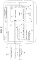
- FIG. 2 is a detailed configuration diagram of the navigation system illustrated in FIG. 1 .
- FIG. 3 is a flowchart illustrating a progression during navigation of an aircraft including a determination as to whether a radio signal is an authentic GPS signal or a deceiving signal by the navigation system incorporating the deceiving signal detection system illustrated in FIG. 1 .
- FIG. 4 is a configuration diagram of a deceiving signal detection system according to a second example of the present invention.
- FIG. 1 is a configuration diagram of a navigation system including a deceiving signal detection system according to a first example of the present invention
- FIG. 2 is a detailed configuration diagram of the navigation system illustrated in FIG. 1 .
- the navigation system 1 is a system configured to receive a navigation signal transmitted as a radio wave signal and navigates a mobile body based on the received navigation signal. Accordingly, the navigation system 1 is mounted on the mobile body.
- the navigation system 1 incorporates a deceiving signal detection system 2 for detecting whether a received radio signal is a deceiving signal disguised as a navigation signal. If the navigation signal received by the navigation system 1 is called a navigation signal including a case where the radio signal is a deceiving signal, the deceiving signal detection system 2 is a system for determining whether the navigation signal received by the navigation system 1 is a deceiving signal.
- the navigation signal will be referred to as a navigation signal including a case where the radio wave signal received by the navigation system 1 is a deceiving signal.
- Examples of mobile bodies include unmanned aircrafts and manned aircrafts 3 as illustrated in FIG. 1 .
- the aircraft 3 may be either a fixed-wing aircraft or a rotating-wing aircraft.
- Other examples of mobile bodies include spacecraft (e.g., missiles, rockets, satellites, etc.), ships, automobiles, and the like.
- spacecraft e.g., missiles, rockets, satellites, etc.
- a GPS signal may be used as the navigation signal for navigating the aircraft 3 , as is typically employed, but other navigation signals may also be used. Specific examples include GNSS signals such as GLONASS signals and Galileo signals, as well as PL signals and LDACS-NAV signals. Further, an alternative navigation signal may be used to navigate the aircraft 3 in case the primary navigation signal used to navigate the aircraft 3 is determined to be a deceiving signal by the deceiving signal detection system 2 .
- a GPS signal transmitted from a GPS satellite 4 is used as a main navigation signal
- a LDACS-NAV signal may be used as a secondary navigation signal when a false radio wave signal disguised as a GPS signal is detected in the deceiving signal detection system 2 .
- the navigation system 1 and the deceiving signal detection system 2 may comprise a first antenna 5 , a second antenna 6 , an inertial measurement unit (IMU) 7 , a signal processor 8 , and a display 9 .
- the display 9 is provided on the aircraft 3 , but in case of the aircraft 3 being an unmanned aircraft to be remotely controlled, the display 9 may be provided on a controller for remote control of the aircraft 3 .
- the IMU 7 may be omitted when the mobile body to be navigated by the navigation system 1 is not an aircraft 3 .
- the first antenna 5 and the second antenna 6 are both antennas for receiving GPS signals transmitted as radio wave signals from a plurality (i.e., on the order of tens) of GPS satellites 4 located at different positions.
- the first antenna 5 and the second antenna 6 are arranged at different positions of the aircraft 3 at a sufficient distance apart so as to be able to detect a difference in reception times of GPS signals.
- the GPS signal transmitted from each GPS satellite 4 includes the spatial position of the GPS satellite 4 represented by latitude, longitude, and altitude (i.e., the transmitting position of the GPS signal), and the transmitting time of the GPS signal.
- the first antenna 5 In order to specify the spatial position of the aircraft 3 , it is necessary for the first antenna 5 to receive GPS signals originating from at least four GPS satellites 4 . Therefore, the first antenna 5 and the second antenna 6 sequentially receive GPS signals indicating the transmitting positions of four or more multiple GPS signals and the transmitting time of signals from the respective positions.
- the IMU 7 is a sensor such as a gyro, an angular velocity meter for sensing angular velocities and accelerations in three directions of the aircraft 3 , and can therefore determine the orientation and the like of the aircraft 3 .
- the signal processor 8 may comprise electronic circuits including an A/D converter (analog-to-digital converter).
- the portion of the signal processor 8 that processes digital information after A/D conversion may be configured by an electronic circuit such as a computer that reads a program.
- the signal processor 8 may be configured so as to be provided with a function for detecting the position of the aircraft 3 by enabling a computer to read a navigation program of the aircraft 3 . Further, by enabling the computer to read a deceiving signal detection program, the signal processor 8 is provided with a deceiving signal detection function for determining whether a radio wave signal received by the first antenna 5 and the second antenna 6 is an authentic GPS signal or a deceiving signal disguised as a GPS signal.
- the signal processor 8 functions as a position detector 10 and a deceiving signal detector 11 .
- the position detector 10 of the signal processor 8 together with the first antenna 5 and the IMU 7 , constitutes an inertial navigation system (INS) 12 which utilizes a GPS signal or a LDACS-NAV signal to improve detection accuracy of the position of the aircraft 3 .
- the deceiving signal detector 11 of the signal processor 8 constitutes the deceiving signal detection system 2 together with the first antenna 5 and the second antenna 6 .
- the INS 12 is a system for calculating the orientation, position, and velocity of the aircraft 3 based on angular velocity and acceleration in three directions of the aircraft 3 detected by the IMU 7 , and for offsetting the position of the aircraft 3 based on the GPS signal or the LDACS-NAV signal received by the first antenna 5 .
- the position detector 10 has a function of calculating the orientation, position, and speed of the aircraft 3 based on angular velocity and acceleration of the aircraft 3 obtained from the IMU 7 , a function of calculating the position of the aircraft 3 based on the GPS signal or the LDACS-NAV signal received by the first antenna 5 , and a function of correcting the position of the aircraft 3 , being calculated by the IMU 7 , with the position of the aircraft 3 , being calculated based on the GPS signal or the LDACS-NAV signal.
- Calculation of the position of the aircraft 3 based on the GPS signals can be performed based on GPS signals transmitted from at least four GPS satellites 4 at different orbital positions. Specifically, the spatial position of the aircraft 3 at the reception time of the GPS signals, being received by the first antenna 5 , can be detected based on the position information of the multiple GPS satellites 4 specified based on the GPS signals, and based on the time differences between the GPS satellites 4 from the transmitting time of each GPS signal to the reception time by the first antenna 5 .
- the position of the aircraft 3 that is calculated by the IMU 7 is corrected based on the spatial position of the aircraft 3 that is detected based on the GPS signals, so that the position of the aircraft 3 can be determined with high accuracy. As a result, the aircraft 3 can be navigated with sufficient accuracy.
- the INS 12 position detector 10 may output highly accurate position information of the aircraft 3 to a flight control system 13 of the aircraft 3 , the position information being detected and corrected based on the GPS signals. This allows the flight control system 13 to automatically control the aircraft 3 such that the aircraft 3 cruises along a predetermined cruise path of the aircraft 3 .
- the aircraft 3 is an unmanned aircraft remotely controlled by an operator or a manned aircraft controlled by a pilot
- the highly accurate position information of the aircraft 3 may be output to the display 9 , the position information being detected and corrected based on the GPS signals.
- the operator of the aircraft 3 can steer the aircraft 3 while referring to the position information of the aircraft 3 displayed on the display 9 .
- a deceiving signal of a GPS signal can be generated by superimposing multiple radio wave signals simulating a GPS signal with predetermined time differences as if the signal was multiple GPS signals transmitted from multiple GPS satellites 4 . Therefore, by adjusting the time differences among the multiple signal components superimposed on the deceiving signal, it is possible to cause the INS 12 of the aircraft 3 to detect the false position of the aircraft 3 .
- the deceiving signal can be easily transmitted from a deceiving signal transmitter 14 with the power higher than strength of an authentic GPS signal. Further, by generating radio jamming, a GPS signal may not be received easily since the strength of GPS signals is small. Therefore, when a deceiving signal of the GPS signal is transmitted, the INS 12 detects the position of the airplane 3 based on the deceiving signal.
- the deceiving signal detection system 2 determines whether the GPS signal is a deceiving signal, and the position detector 10 of the INS 12 is configured to halt the detection with relying on the GPS signal of the aircraft 3 position, when the GPS signal is determined to be a deceiving signal.
- the aircraft 3 may then be maneuvered based on the position of the aircraft 3 calculated in the IMU 7 provided in the INS 12 without using GPS signals. That is, the position of the aircraft 3 calculated by the IMU 7 provided in the INS 12 may be used as is for navigating the aircraft 3 without corrections.
- the position detector 10 of the INS 12 may detect the position of the airplane 3 based on the LDACS-NAV signal, which is a well-known navigational signal based on a communication protocol different from the communication protocol of the GPS signal. That is, the navigation signal for correcting the position of the airplane 3 calculated by the IMU 7 can be switched from the GPS signal to the LDACS-NAV signal having a different frequency or the like.
- the calculation of the position of the airplane 3 based on the LDACS-NAV signal can be performed based on the LDACS-NAV signal transmitted from at least four signal transmitters 15 installed at different positions on the ground or on the sea.
- the spatial position of the aircraft 3 at the reception time of the LDACS-NAV signals received by the first antenna 5 can be detected based on the position information of the multiple signal transmitters 15 specified from the LDACS-NAV signal, and based on the time differences of the signal transmitting devices 15 , each time difference being between the transmitting time of each LDACS-NAV signal and the reception time by the first antenna 5 .
- a signal transmitter 15 of the LDACS-NAV signal may be disposed at sea by mooring the signal transmitter 15 to the seafloor by an anchor buoy, as described in Japanese patent application No. 2017-224072.
- each of the signal transmitters 15 may be provided with a function of detecting the position of itself by communicating with three or more transponders fixed to the seafloor, without using the GPS signal.
- the deceiving signal detector 11 constituting the deceiving signal detection system 2 has a function of detecting whether the multiple GPS signals are the multiple signal components constituting the deceiving signal based on the multiple GPS signals received by the first antenna 5 and the multiple GPS signals received by the second antenna 6 . That is, the deceiving signal detector 11 has a function of verifying the multiple GPS signals which may be multiple signal components constituting the deceiving signal.
- the multiple authentic GPS signals required for detecting the spatial position of the aircraft 3 are transmitted from the multiple GPS satellites 4 at different positions, whereas the multiple signal components superimposed on the deceiving signal simulating the multiple GPS signals are transmitted from a deceiving signal transmitter 14 installed at one position.
- the deceiving signal is received by the first antenna 5 and the second antenna 6 , it is possible to detect that a difference in arrival time of the multiple signal components constituting the deceiving signal is different from a difference in arrival time of the multiple authentic GPS signals.
- an arrival time of each GPS signal transmitted from the GPS satellite 4 to the first antenna 5 and an arrival time of the GPS signal to the second antenna 6 will be different not only with respect to other GPS signals but also with respect to the first antenna 5 and the second antenna 6 .
- the combination of the arrival time differences of the multiple GPS signals should be different with respect to the first antenna 5 and the second antenna 6 .
- the reception time of each authentic GPS signal transmitted at the same time will be different in the first antenna 5 and the second antenna 6 , while the transmitting time of each authentic GPS signal received at the same time at the first antenna 5 and at the second antenna 6 might be also different.
- the multiple signal components constituting the deceiving signal are received by the first antenna 5 and the second antenna 6 , the reception time differences of the multiple signal components associated with the same transmitting time are the same at the first antenna 5 and at the second antenna 6 , while the transmitting time differences associated with the multiple signal components received at the same time by the first antenna 5 and by the second antenna 6 are the same at the first antenna 5 and at the second antenna 6 .
- the multiple signal components received by the first antenna 5 and the second antenna 6 are signal components that are temporally offset by the distance between the first antenna 5 and the second antenna 6 .
- the deceiving signal by detecting the characteristics of the multiple signal components constituting the deceiving signal, it is possible to determine whether four or more multiple radio wave signals indicating the transmitting position and the transmitting time of the signals received by the first antenna 5 and the second antenna 6 are the multiple GPS signals transmitted from different GPS satellites 4 or deceiving signals disguised as GPS signals.
- the multiple radio wave signals are multiple signal components constituting a deceiving signal.
- the positions of the first antenna 5 and the second antenna 6 may be calculated based on the multiple radio wave signals received. It may be checked whether the calculated distance between the positions of the first antenna 5 and the second antenna 6 is the same as the actual distance, and whether the orientation of the aircraft 3 , being specified based on the positions of the first antenna 5 and the second antenna 6 , matches the orientation of the aircraft 3 that is calculated by the INS 12 .
- the multiple radio wave signals are multiple signal components constituting a deceiving signal.
- the deceiving signal may be detected with a certain degree of accuracy.
- the detection accuracy of the deceiving signal may be improved not only by comparing the distances between the first antenna 5 and the second antenna 6 , but also by comparing the relative positions by vector expressions, including the direction of one with respect to the other, with the actual relative position.
- the actual relative position between the first antenna 5 and the second antenna 6 can be calculated geometrically based on the orientation of the aircraft 3 calculated by the INS 12 (i.e., the orientation of the aircraft 3 relative to a reference orientation) and the actual relative distance between the first antenna 5 and the second antenna 6 .
- the deceiving signal detector 11 may be provided with: a function of calculating the relative position of the first antenna 5 and the second antenna 6 based on the multiple radio wave signals received by the first antenna 5 and the second antenna 6 ; a function of calculating the actual relative position between the first antenna 5 and the second antenna 6 based on the orientation of the airplane 3 calculated by the INS 12 and the actual distance between the first antenna 5 and the second antenna 6 , and a function of detecting the deceiving signal by comparing the relative distance between the first antenna 5 and the second antenna 6 calculated by the aforementioned two calculation methods.
- a necessary calculation function may be provided in the deceiving signal detector 11 .
- FIG. 3 is a flowchart illustrating a progression during navigation of an aircraft 3 including a determination as to whether a radio signal is an authentic GPS signal or a deceiving signal by the navigation system 1 incorporating the deceiving signal detection system 2 illustrated in FIG. 1 .
- step S 1 four or more multiple GPS signals are received by the first antenna 5 and the second antenna 6 provided in the aircraft 3 .
- the multiple GPS signals received by the first antenna 5 and the second antenna 6 may be multiple signal components constituting a deceiving signal.
- the first antenna 5 and the second antenna 6 provided in the aircraft 3 receive four or more multiple radio wave signals to be checked to determine if the signals are multiple signal components constituting a deceiving signal or multiple authentic GPS signals transmitted from different GPS satellites 4 .
- the deceiving signal detector 11 of the deceiving signal detection system 2 obtains multiple radio wave signals received by the first antenna 5 and the second antenna 6 , that is, multiple GPS signals which may be multiple signal components constituting a deceiving signal.
- step S 2 the deceiving signal detector 11 calculates the relative position between the first antenna 5 and the second antenna 6 based on the two sets of obtained radio wave signals. That is, since the transmitting position and the transmitting time of the signal can be read from each radio wave signal, the position of the first antenna 5 and the position of the second antenna 6 can be calculated based on the difference in the arrival time from the transmitting time to the reception time of each radio wave signal. As a result, the relative positions of the first antenna 5 and the second antenna 6 can also be calculated.
- step S 3 it is determined whether the relative positions of the first antenna 5 and the second antenna 6 calculated based on the multiple GPS signals, being received by the first antenna 5 and the second antenna 6 , matches with the actual relative positions of the first antenna 5 and the second antenna 6 specified based on the orientation information of the aircraft 3 calculated by the INS 12 .
- the GPS signals may be the multiple signal components constituting a deceiving signal.
- step S 4 navigation of the aircraft 3 based on the GPS signal is performed. Specifically, the position detector 10 detects the position of the aircraft 3 based on the multiple GPS signals received by the first antenna 5 . The aircraft 3 is then maneuvered based on the detected position of the aircraft 3 .
- the position of the aircraft 3 detected by the position detector 10 is output to the flight control system 13 of the aircraft 3 .
- This allows the flight control system 13 to automatically control the aircraft 3 such that the aircraft 3 cruises along a predetermined cruise path of the aircraft 3 .
- the position of the aircraft 3 detected by the position detector 10 is displayed on the display 9 .
- the operator of the aircraft 3 can steer the aircraft 3 while referring to the position information of the aircraft 3 displayed on the display 9 .
- the multiple GPS signals are determined to be the multiple signal components constituting a deceiving signal.
- step S 5 the process switches to navigation of the aircraft 3 based on a substitute signal. That is, the navigation of the aircraft 3 based on the GPS signal is stopped, and the navigation of the aircraft 3 based on a substitute signal such as a LDACS-NAV signal is executed. Specifically, the position detector 10 detects the position of the aircraft 3 based on the substitute signals such as multiple DACS-NAV signals received by the first antenna 5 . The aircraft 3 is then maneuvered based on the detected position of the aircraft 3 .
- a substitute signal such as a LDACS-NAV signal
- Navigation of the aircraft 3 based on the substitute signals may continue until it is determined in step S 3 that the multiple radio wave signals received by the first antenna 5 and the second antenna 6 are authentic GPS signals that are not deceiving signals. In this case, the navigation of the aircraft 3 can be continued without being misguided by a deceiving signal.
- the navigation signal such as the GPS signal is received by the first antenna 5 and the second antenna 6 which are arranged apart from each other, and a deceiving signal can be detected by detecting an inconsistency with respect to the arrival time of the signals, which is derived from the deceiving signal disguised as the navigation signal being transmitted from the same position.
- the deceiving signal detection system 2 even when a deceiving signal disguised as a navigation signal is transmitted, it is possible to prevent a moving body such as an aircraft 3 from proceeding on an erroneous route.
- a moving body such as an aircraft 3
- an unmanned mobile body is automatically operated using a navigation signal, it is possible to prevent the originator of the deceiving signal from controlling the mobile body, and attempting falling, sinking or stealing of the mobile body.
- FIG. 4 is a configuration diagram of a deceiving signal detection system according to a second example of the present invention.
- the deceiving signal detection system 2 A in the second example illustrated in FIG. 4 differs from the deceiving signal detection system 2 in the first example in that the first antenna 5 and the second antenna 6 are provided on a stationary base on the ground or on the sea. Since the configuration and operation of the deceiving signal detection system 2 A in the second example are not substantially different from those of the deceiving signal detection system 2 in the first example, the same reference numerals are assigned to the same configurations or corresponding configurations, and descriptions thereof are omitted.
- the first antenna 5 and the second antenna 6 constituting the deceiving signal detection system 2 A may be installed on a stationary base on the ground or on the sea as long as they are within the coverage area of the navigation signal such as the GPS signal. Even in this case, it is possible to determine whether the radio wave signal received by the first antenna 5 and the second antenna 6 is an authentic navigation signal such as a GPS signal or a deceiving signal disguised as a navigation signal by the same algorithm as in the first example.
- the deceiving signal detection system 2 A including the first antenna 5 and the second antenna 6 can be installed in a camp site or an observation site operated temporarily, and it can be easily determined whether the radio signal received by the first antenna 5 and the second antenna 6 is a navigation signal or a deceiving signal.
- the first antenna 5 and the second antenna 6 may be attached to a portable terminal constituting the signal processor 8 , and the deceiving signal detection system 2 A or the navigation system 1 including the deceiving signal detection system 2 A may be carried by a user.
- a small-sized deceiving signal detection system 2 A or a small-sized navigation system 1 incorporating the deceiving signal detection system 2 A may be configured to be wearable on an animal such as a bird or a dog.
- the mobile body on which the navigation system 1 is mounted in the first example may be a moving living things such as a user.
Landscapes
- Engineering & Computer Science (AREA)
- Radar, Positioning & Navigation (AREA)
- Remote Sensing (AREA)
- Computer Networks & Wireless Communication (AREA)
- Signal Processing (AREA)
- Physics & Mathematics (AREA)
- General Physics & Mathematics (AREA)
- Position Fixing By Use Of Radio Waves (AREA)
- Navigation (AREA)
Abstract
Description
Claims (6)
Applications Claiming Priority (3)
| Application Number | Priority Date | Filing Date | Title |
|---|---|---|---|
| JPJP2017-236559 | 2017-12-11 | ||
| JP2017236559A JP6691096B2 (en) | 2017-12-11 | 2017-12-11 | Deception signal detection system and deception signal detection method |
| JP2017-236559 | 2017-12-11 |
Publications (2)
| Publication Number | Publication Date |
|---|---|
| US20190179033A1 US20190179033A1 (en) | 2019-06-13 |
| US11215714B2 true US11215714B2 (en) | 2022-01-04 |
Family
ID=66696696
Family Applications (1)
| Application Number | Title | Priority Date | Filing Date |
|---|---|---|---|
| US16/186,299 Active 2039-07-05 US11215714B2 (en) | 2017-12-11 | 2018-11-09 | Deceiving signal detection system and deceiving signal detection method |
Country Status (2)
| Country | Link |
|---|---|
| US (1) | US11215714B2 (en) |
| JP (1) | JP6691096B2 (en) |
Cited By (2)
| Publication number | Priority date | Publication date | Assignee | Title |
|---|---|---|---|---|
| US20220167292A1 (en) * | 2020-11-26 | 2022-05-26 | Kabushiki Kaisha Tokai Rika Denki Seisakusho | Wireless communication device, system, and storage medium |
| US11480689B2 (en) * | 2018-11-14 | 2022-10-25 | Ge Aviation Systems Limited | Detecting the spoofing of a signal |
Families Citing this family (9)
| Publication number | Priority date | Publication date | Assignee | Title |
|---|---|---|---|---|
| CN111007552B (en) * | 2019-11-07 | 2021-09-07 | 北京航空航天大学 | Air-ground co-location and integrity monitoring method based on LDACS |
| WO2021166222A1 (en) * | 2020-02-21 | 2021-08-26 | 日本電気株式会社 | Positioning device and positioning method |
| CN111983648B (en) * | 2020-05-21 | 2024-04-02 | 深圳市西博泰科电子有限公司 | Satellite navigation deception detection method, device, equipment and medium |
| US12399274B2 (en) * | 2020-07-10 | 2025-08-26 | Skystream LLC | Enhanced LDACS that uses doppler shifts in carrier signals for positioning and navigation |
| US11909501B2 (en) * | 2020-07-10 | 2024-02-20 | Skystream LLC | Enhanced LDACS system having roaming agreements and associated methods |
| US11054525B1 (en) * | 2020-11-19 | 2021-07-06 | Flex Force Enterprises Inc. | GNSS simulation to disrupt unmanned vehicle operation |
| KR102401940B1 (en) * | 2020-12-22 | 2022-05-24 | 주식회사 한화 | Apparatus and method for operating measuring deceptive devices |
| KR20220149203A (en) * | 2021-04-30 | 2022-11-08 | 현대자동차주식회사 | Mobility device and controlling method of vehicle |
| CN116859418B (en) * | 2023-07-05 | 2024-01-26 | 中国人民解放军92728部队 | Satellite navigation deception jamming detection method based on relay platform monitoring |
Citations (12)
| Publication number | Priority date | Publication date | Assignee | Title |
|---|---|---|---|---|
| US6259398B1 (en) * | 2000-05-19 | 2001-07-10 | Sri International | Multi-valued variable ambiguity resolution for satellite navigation signal carrier wave path length determination |
| JP2001280997A (en) * | 2000-03-30 | 2001-10-10 | Japan Radio Co Ltd | GNSS / inertial navigation system |
| US6710739B1 (en) | 2003-01-03 | 2004-03-23 | Northrop Grumman Corporation | Dual redundant GPS anti-jam air vehicle navigation system architecture and method |
| US7221312B2 (en) * | 2003-06-18 | 2007-05-22 | General Dynamics C4 Systems, Inc. | Method and system for detecting interference for global positioning systems |
| US7310062B1 (en) * | 2005-07-28 | 2007-12-18 | Rockwell Collins, Inc. | Dual antenna diversity method to detect GPS signal tampering |
| US7564401B1 (en) * | 2004-08-10 | 2009-07-21 | Northrop Grumman Corporation | Signal inconsistency detection of spoofing |
| US20150116146A1 (en) * | 2013-10-29 | 2015-04-30 | Northrop Grumman Systems Corporation | Anomaly detection using an antenna baseline constraint |
| US20150226858A1 (en) * | 2014-02-13 | 2015-08-13 | The Mitre Corporation | GPS Spoofing Detection Techniques |
| US20170192103A1 (en) * | 2016-01-06 | 2017-07-06 | Honeywell International Inc. | Systems and methods for vehicle attitude determination |
| US10054687B2 (en) * | 2013-08-14 | 2018-08-21 | Hemisphere Gnss Inc. | System and method for detecting false global navigation satellite system satellite signals |
| US10162060B2 (en) * | 2013-10-31 | 2018-12-25 | Southwest Research Institute | Determination of integrity of incoming signals of satellite navigation system |
| US10677933B1 (en) * | 2017-08-09 | 2020-06-09 | Rockwell Collins, Inc. | Heading or pitch determination systems and methods with high confidence error bounds |
Family Cites Families (5)
| Publication number | Priority date | Publication date | Assignee | Title |
|---|---|---|---|---|
| US5557284A (en) * | 1995-02-03 | 1996-09-17 | Honeywell Inc. | Spoofing detection system for a satellite positioning system |
| JP2013047642A (en) * | 2011-08-29 | 2013-03-07 | Toyota Motor Corp | System and method for locating gps interference source |
| DE102012007192B4 (en) * | 2012-04-12 | 2014-05-08 | Astrium Gmbh | Detection of forged signals in a satellite navigation system |
| JP6017984B2 (en) * | 2013-02-05 | 2016-11-02 | 公益財団法人鉄道総合技術研究所 | Vehicle position measuring method and vehicle position measuring system |
| US10234564B2 (en) * | 2013-08-14 | 2019-03-19 | Hemisphere Gnss Inc. | System and method for determining the direction of a false GNSS satellite signal transmitter |
-
2017
- 2017-12-11 JP JP2017236559A patent/JP6691096B2/en active Active
-
2018
- 2018-11-09 US US16/186,299 patent/US11215714B2/en active Active
Patent Citations (13)
| Publication number | Priority date | Publication date | Assignee | Title |
|---|---|---|---|---|
| JP2001280997A (en) * | 2000-03-30 | 2001-10-10 | Japan Radio Co Ltd | GNSS / inertial navigation system |
| US6259398B1 (en) * | 2000-05-19 | 2001-07-10 | Sri International | Multi-valued variable ambiguity resolution for satellite navigation signal carrier wave path length determination |
| US6710739B1 (en) | 2003-01-03 | 2004-03-23 | Northrop Grumman Corporation | Dual redundant GPS anti-jam air vehicle navigation system architecture and method |
| JP2006513084A (en) | 2003-01-03 | 2006-04-20 | ノースロップ グラマン コーポレイション | Aircraft navigation system using double redundant GPS to prevent interference |
| US7221312B2 (en) * | 2003-06-18 | 2007-05-22 | General Dynamics C4 Systems, Inc. | Method and system for detecting interference for global positioning systems |
| US7564401B1 (en) * | 2004-08-10 | 2009-07-21 | Northrop Grumman Corporation | Signal inconsistency detection of spoofing |
| US7310062B1 (en) * | 2005-07-28 | 2007-12-18 | Rockwell Collins, Inc. | Dual antenna diversity method to detect GPS signal tampering |
| US10054687B2 (en) * | 2013-08-14 | 2018-08-21 | Hemisphere Gnss Inc. | System and method for detecting false global navigation satellite system satellite signals |
| US20150116146A1 (en) * | 2013-10-29 | 2015-04-30 | Northrop Grumman Systems Corporation | Anomaly detection using an antenna baseline constraint |
| US10162060B2 (en) * | 2013-10-31 | 2018-12-25 | Southwest Research Institute | Determination of integrity of incoming signals of satellite navigation system |
| US20150226858A1 (en) * | 2014-02-13 | 2015-08-13 | The Mitre Corporation | GPS Spoofing Detection Techniques |
| US20170192103A1 (en) * | 2016-01-06 | 2017-07-06 | Honeywell International Inc. | Systems and methods for vehicle attitude determination |
| US10677933B1 (en) * | 2017-08-09 | 2020-06-09 | Rockwell Collins, Inc. | Heading or pitch determination systems and methods with high confidence error bounds |
Non-Patent Citations (1)
| Title |
|---|
| Jafarnia-Jahromi et al. "GPS Vulnerability to Spoofing Threats and a Review of Antispoofing Techniques." Hindawi Publishing Corp. International Journal of Navigation and Observation. vol. 2012. Article ID 127072. 16 pages. (Year: 2012). * |
Cited By (3)
| Publication number | Priority date | Publication date | Assignee | Title |
|---|---|---|---|---|
| US11480689B2 (en) * | 2018-11-14 | 2022-10-25 | Ge Aviation Systems Limited | Detecting the spoofing of a signal |
| US11860283B2 (en) | 2018-11-14 | 2024-01-02 | Ge Aviation Systems Limited | Detecting the spoofing of a signal |
| US20220167292A1 (en) * | 2020-11-26 | 2022-05-26 | Kabushiki Kaisha Tokai Rika Denki Seisakusho | Wireless communication device, system, and storage medium |
Also Published As
| Publication number | Publication date |
|---|---|
| US20190179033A1 (en) | 2019-06-13 |
| JP2019105465A (en) | 2019-06-27 |
| JP6691096B2 (en) | 2020-04-28 |
Similar Documents
| Publication | Publication Date | Title |
|---|---|---|
| US11215714B2 (en) | Deceiving signal detection system and deceiving signal detection method | |
| US11693122B1 (en) | Global navigation satellite system spoofer identification technique | |
| US20240385333A1 (en) | Vehicle navigation combining transmitted object location information and sensor-based relative object location information | |
| US10768309B1 (en) | Global navigation satellite system beam based attitude determination | |
| US12204034B2 (en) | Stratospheric position, navigation, and timing system | |
| US10254392B2 (en) | Reverse-ephemeris method for determining position, attitude, and time | |
| US7098846B2 (en) | All-weather precision guidance and navigation system | |
| EP2660619A1 (en) | Near field navigation system | |
| JPH08504944A (en) | Method and apparatus for monitoring and remote controlling a mobile unmanned underwater vehicle | |
| US8868256B2 (en) | Relative navigation for aerial refueling of an unmanned aerial vehicle | |
| KR101015039B1 (en) | Underwater localization system and method | |
| KR20150051747A (en) | Method for determining location of vehicle | |
| US12163764B2 (en) | System and method for navigation and targeting in GPS-challenged environments using factor graph optimization | |
| US7688264B2 (en) | Method and apparatus for passive single platform geo-location | |
| US20060178829A1 (en) | Global acoustic positioning system and device | |
| Son et al. | Enhancing coastal air navigation: eloran 3-D positioning and cycle slip mitigation | |
| JP2001280997A (en) | GNSS / inertial navigation system | |
| CN117249824A (en) | An inertial satellite fusion positioning method and system | |
| US10976439B2 (en) | Navigation system and navigation method | |
| WO2017141614A1 (en) | Tsunami observation device, tsunami observation system, and tsunami observation method | |
| WO2017066750A1 (en) | Triple difference formulation for formation flight | |
| JP2008241079A (en) | Navigation system | |
| Albrektsen et al. | Navigation of uav using phased array radio | |
| KR101960164B1 (en) | A method for calculating a Real-Time Heading value of object using EKF-Cl | |
| US10234874B2 (en) | Autonomous vehicle control system |
Legal Events
| Date | Code | Title | Description |
|---|---|---|---|
| AS | Assignment |
Owner name: SUBARU CORPORATION, JAPAN Free format text: ASSIGNMENT OF ASSIGNORS INTEREST;ASSIGNORS:SASAKI, YUTAKA;SAKAGUCHI, AKITOSHI;YAMANE, AKIHITO;AND OTHERS;REEL/FRAME:047466/0989 Effective date: 20181005 |
|
| FEPP | Fee payment procedure |
Free format text: ENTITY STATUS SET TO UNDISCOUNTED (ORIGINAL EVENT CODE: BIG.); ENTITY STATUS OF PATENT OWNER: LARGE ENTITY |
|
| STPP | Information on status: patent application and granting procedure in general |
Free format text: DOCKETED NEW CASE - READY FOR EXAMINATION |
|
| STPP | Information on status: patent application and granting procedure in general |
Free format text: NON FINAL ACTION MAILED |
|
| STPP | Information on status: patent application and granting procedure in general |
Free format text: FINAL REJECTION MAILED |
|
| STPP | Information on status: patent application and granting procedure in general |
Free format text: DOCKETED NEW CASE - READY FOR EXAMINATION |
|
| STPP | Information on status: patent application and granting procedure in general |
Free format text: NON FINAL ACTION MAILED |
|
| STPP | Information on status: patent application and granting procedure in general |
Free format text: NOTICE OF ALLOWANCE MAILED -- APPLICATION RECEIVED IN OFFICE OF PUBLICATIONS |
|
| STPP | Information on status: patent application and granting procedure in general |
Free format text: PUBLICATIONS -- ISSUE FEE PAYMENT VERIFIED |
|
| STCF | Information on status: patent grant |
Free format text: PATENTED CASE |
|
| MAFP | Maintenance fee payment |
Free format text: PAYMENT OF MAINTENANCE FEE, 4TH YEAR, LARGE ENTITY (ORIGINAL EVENT CODE: M1551); ENTITY STATUS OF PATENT OWNER: LARGE ENTITY Year of fee payment: 4 |