US11215337B2 - Puddle lamp - Google Patents
Puddle lamp Download PDFInfo
- Publication number
- US11215337B2 US11215337B2 US16/916,172 US202016916172A US11215337B2 US 11215337 B2 US11215337 B2 US 11215337B2 US 202016916172 A US202016916172 A US 202016916172A US 11215337 B2 US11215337 B2 US 11215337B2
- Authority
- US
- United States
- Prior art keywords
- optical axis
- light source
- lens
- puddle lamp
- lens set
- Prior art date
- Legal status (The legal status is an assumption and is not a legal conclusion. Google has not performed a legal analysis and makes no representation as to the accuracy of the status listed.)
- Expired - Fee Related
Links
Images


Classifications
-
- F—MECHANICAL ENGINEERING; LIGHTING; HEATING; WEAPONS; BLASTING
- F21—LIGHTING
- F21S—NON-PORTABLE LIGHTING DEVICES; SYSTEMS THEREOF; VEHICLE LIGHTING DEVICES SPECIALLY ADAPTED FOR VEHICLE EXTERIORS
- F21S43/00—Signalling devices specially adapted for vehicle exteriors, e.g. brake lamps, direction indicator lights or reversing lights
- F21S43/20—Signalling devices specially adapted for vehicle exteriors, e.g. brake lamps, direction indicator lights or reversing lights characterised by refractors, transparent cover plates, light guides or filters
- F21S43/26—Refractors, transparent cover plates, light guides or filters not provided in groups F21S43/235 - F21S43/255
-
- B—PERFORMING OPERATIONS; TRANSPORTING
- B60—VEHICLES IN GENERAL
- B60Q—ARRANGEMENT OF SIGNALLING OR LIGHTING DEVICES, THE MOUNTING OR SUPPORTING THEREOF OR CIRCUITS THEREFOR, FOR VEHICLES IN GENERAL
- B60Q1/00—Arrangement of optical signalling or lighting devices, the mounting or supporting thereof or circuits therefor
- B60Q1/26—Arrangement of optical signalling or lighting devices, the mounting or supporting thereof or circuits therefor the devices being primarily intended to indicate the vehicle, or parts thereof, or to give signals, to other traffic
- B60Q1/2661—Arrangement of optical signalling or lighting devices, the mounting or supporting thereof or circuits therefor the devices being primarily intended to indicate the vehicle, or parts thereof, or to give signals, to other traffic mounted on parts having other functions
- B60Q1/2665—Arrangement of optical signalling or lighting devices, the mounting or supporting thereof or circuits therefor the devices being primarily intended to indicate the vehicle, or parts thereof, or to give signals, to other traffic mounted on parts having other functions on rear-view mirrors
-
- B—PERFORMING OPERATIONS; TRANSPORTING
- B60—VEHICLES IN GENERAL
- B60Q—ARRANGEMENT OF SIGNALLING OR LIGHTING DEVICES, THE MOUNTING OR SUPPORTING THEREOF OR CIRCUITS THEREFOR, FOR VEHICLES IN GENERAL
- B60Q1/00—Arrangement of optical signalling or lighting devices, the mounting or supporting thereof or circuits therefor
- B60Q1/02—Arrangement of optical signalling or lighting devices, the mounting or supporting thereof or circuits therefor the devices being primarily intended to illuminate the way ahead or to illuminate other areas of way or environments
- B60Q1/24—Arrangement of optical signalling or lighting devices, the mounting or supporting thereof or circuits therefor the devices being primarily intended to illuminate the way ahead or to illuminate other areas of way or environments for lighting other areas than only the way ahead
- B60Q1/247—Arrangement of optical signalling or lighting devices, the mounting or supporting thereof or circuits therefor the devices being primarily intended to illuminate the way ahead or to illuminate other areas of way or environments for lighting other areas than only the way ahead for illuminating the close surroundings of the vehicle, e.g. to facilitate entry or exit
-
- B—PERFORMING OPERATIONS; TRANSPORTING
- B60—VEHICLES IN GENERAL
- B60Q—ARRANGEMENT OF SIGNALLING OR LIGHTING DEVICES, THE MOUNTING OR SUPPORTING THEREOF OR CIRCUITS THEREFOR, FOR VEHICLES IN GENERAL
- B60Q1/00—Arrangement of optical signalling or lighting devices, the mounting or supporting thereof or circuits therefor
- B60Q1/26—Arrangement of optical signalling or lighting devices, the mounting or supporting thereof or circuits therefor the devices being primarily intended to indicate the vehicle, or parts thereof, or to give signals, to other traffic
- B60Q1/32—Arrangement of optical signalling or lighting devices, the mounting or supporting thereof or circuits therefor the devices being primarily intended to indicate the vehicle, or parts thereof, or to give signals, to other traffic for indicating vehicle sides, e.g. clearance lights
-
- F—MECHANICAL ENGINEERING; LIGHTING; HEATING; WEAPONS; BLASTING
- F21—LIGHTING
- F21S—NON-PORTABLE LIGHTING DEVICES; SYSTEMS THEREOF; VEHICLE LIGHTING DEVICES SPECIALLY ADAPTED FOR VEHICLE EXTERIORS
- F21S41/00—Illuminating devices specially adapted for vehicle exteriors, e.g. headlamps
- F21S41/10—Illuminating devices specially adapted for vehicle exteriors, e.g. headlamps characterised by the light source
- F21S41/14—Illuminating devices specially adapted for vehicle exteriors, e.g. headlamps characterised by the light source characterised by the type of light source
- F21S41/141—Light emitting diodes [LED]
- F21S41/143—Light emitting diodes [LED] the main emission direction of the LED being parallel to the optical axis of the illuminating device
-
- F—MECHANICAL ENGINEERING; LIGHTING; HEATING; WEAPONS; BLASTING
- F21—LIGHTING
- F21S—NON-PORTABLE LIGHTING DEVICES; SYSTEMS THEREOF; VEHICLE LIGHTING DEVICES SPECIALLY ADAPTED FOR VEHICLE EXTERIORS
- F21S41/00—Illuminating devices specially adapted for vehicle exteriors, e.g. headlamps
- F21S41/10—Illuminating devices specially adapted for vehicle exteriors, e.g. headlamps characterised by the light source
- F21S41/14—Illuminating devices specially adapted for vehicle exteriors, e.g. headlamps characterised by the light source characterised by the type of light source
- F21S41/141—Light emitting diodes [LED]
- F21S41/147—Light emitting diodes [LED] the main emission direction of the LED being angled to the optical axis of the illuminating device
-
- F—MECHANICAL ENGINEERING; LIGHTING; HEATING; WEAPONS; BLASTING
- F21—LIGHTING
- F21S—NON-PORTABLE LIGHTING DEVICES; SYSTEMS THEREOF; VEHICLE LIGHTING DEVICES SPECIALLY ADAPTED FOR VEHICLE EXTERIORS
- F21S41/00—Illuminating devices specially adapted for vehicle exteriors, e.g. headlamps
- F21S41/20—Illuminating devices specially adapted for vehicle exteriors, e.g. headlamps characterised by refractors, transparent cover plates, light guides or filters
- F21S41/25—Projection lenses
-
- F—MECHANICAL ENGINEERING; LIGHTING; HEATING; WEAPONS; BLASTING
- F21—LIGHTING
- F21S—NON-PORTABLE LIGHTING DEVICES; SYSTEMS THEREOF; VEHICLE LIGHTING DEVICES SPECIALLY ADAPTED FOR VEHICLE EXTERIORS
- F21S41/00—Illuminating devices specially adapted for vehicle exteriors, e.g. headlamps
- F21S41/20—Illuminating devices specially adapted for vehicle exteriors, e.g. headlamps characterised by refractors, transparent cover plates, light guides or filters
- F21S41/285—Refractors, transparent cover plates, light guides or filters not provided in groups F21S41/24 - F21S41/2805
-
- F—MECHANICAL ENGINEERING; LIGHTING; HEATING; WEAPONS; BLASTING
- F21—LIGHTING
- F21S—NON-PORTABLE LIGHTING DEVICES; SYSTEMS THEREOF; VEHICLE LIGHTING DEVICES SPECIALLY ADAPTED FOR VEHICLE EXTERIORS
- F21S43/00—Signalling devices specially adapted for vehicle exteriors, e.g. brake lamps, direction indicator lights or reversing lights
- F21S43/20—Signalling devices specially adapted for vehicle exteriors, e.g. brake lamps, direction indicator lights or reversing lights characterised by refractors, transparent cover plates, light guides or filters
- F21S43/2605—Refractors
-
- G—PHYSICS
- G03—PHOTOGRAPHY; CINEMATOGRAPHY; ANALOGOUS TECHNIQUES USING WAVES OTHER THAN OPTICAL WAVES; ELECTROGRAPHY; HOLOGRAPHY
- G03B—APPARATUS OR ARRANGEMENTS FOR TAKING PHOTOGRAPHS OR FOR PROJECTING OR VIEWING THEM; APPARATUS OR ARRANGEMENTS EMPLOYING ANALOGOUS TECHNIQUES USING WAVES OTHER THAN OPTICAL WAVES; ACCESSORIES THEREFOR
- G03B21/00—Projectors or projection-type viewers; Accessories therefor
- G03B21/14—Details
- G03B21/20—Lamp housings
- G03B21/208—Homogenising, shaping of the illumination light
-
- B—PERFORMING OPERATIONS; TRANSPORTING
- B60—VEHICLES IN GENERAL
- B60Q—ARRANGEMENT OF SIGNALLING OR LIGHTING DEVICES, THE MOUNTING OR SUPPORTING THEREOF OR CIRCUITS THEREFOR, FOR VEHICLES IN GENERAL
- B60Q1/00—Arrangement of optical signalling or lighting devices, the mounting or supporting thereof or circuits therefor
- B60Q1/26—Arrangement of optical signalling or lighting devices, the mounting or supporting thereof or circuits therefor the devices being primarily intended to indicate the vehicle, or parts thereof, or to give signals, to other traffic
- B60Q1/32—Arrangement of optical signalling or lighting devices, the mounting or supporting thereof or circuits therefor the devices being primarily intended to indicate the vehicle, or parts thereof, or to give signals, to other traffic for indicating vehicle sides, e.g. clearance lights
- B60Q1/323—Arrangement of optical signalling or lighting devices, the mounting or supporting thereof or circuits therefor the devices being primarily intended to indicate the vehicle, or parts thereof, or to give signals, to other traffic for indicating vehicle sides, e.g. clearance lights on or for doors
-
- B—PERFORMING OPERATIONS; TRANSPORTING
- B60—VEHICLES IN GENERAL
- B60Q—ARRANGEMENT OF SIGNALLING OR LIGHTING DEVICES, THE MOUNTING OR SUPPORTING THEREOF OR CIRCUITS THEREFOR, FOR VEHICLES IN GENERAL
- B60Q2400/00—Special features or arrangements of exterior signal lamps for vehicles
- B60Q2400/40—Welcome lights, i.e. specific or existing exterior lamps to assist leaving or approaching the vehicle
-
- F—MECHANICAL ENGINEERING; LIGHTING; HEATING; WEAPONS; BLASTING
- F21—LIGHTING
- F21W—INDEXING SCHEME ASSOCIATED WITH SUBCLASSES F21K, F21L, F21S and F21V, RELATING TO USES OR APPLICATIONS OF LIGHTING DEVICES OR SYSTEMS
- F21W2102/00—Exterior vehicle lighting devices for illuminating purposes
- F21W2102/40—Exterior vehicle lighting devices for illuminating purposes the light being emitted to facilitate access to the vehicle
-
- F—MECHANICAL ENGINEERING; LIGHTING; HEATING; WEAPONS; BLASTING
- F21—LIGHTING
- F21W—INDEXING SCHEME ASSOCIATED WITH SUBCLASSES F21K, F21L, F21S and F21V, RELATING TO USES OR APPLICATIONS OF LIGHTING DEVICES OR SYSTEMS
- F21W2107/00—Use or application of lighting devices on or in particular types of vehicles
-
- G—PHYSICS
- G03—PHOTOGRAPHY; CINEMATOGRAPHY; ANALOGOUS TECHNIQUES USING WAVES OTHER THAN OPTICAL WAVES; ELECTROGRAPHY; HOLOGRAPHY
- G03B—APPARATUS OR ARRANGEMENTS FOR TAKING PHOTOGRAPHS OR FOR PROJECTING OR VIEWING THEM; APPARATUS OR ARRANGEMENTS EMPLOYING ANALOGOUS TECHNIQUES USING WAVES OTHER THAN OPTICAL WAVES; ACCESSORIES THEREFOR
- G03B21/00—Projectors or projection-type viewers; Accessories therefor
- G03B21/001—Slide projectors
-
- G—PHYSICS
- G03—PHOTOGRAPHY; CINEMATOGRAPHY; ANALOGOUS TECHNIQUES USING WAVES OTHER THAN OPTICAL WAVES; ELECTROGRAPHY; HOLOGRAPHY
- G03B—APPARATUS OR ARRANGEMENTS FOR TAKING PHOTOGRAPHS OR FOR PROJECTING OR VIEWING THEM; APPARATUS OR ARRANGEMENTS EMPLOYING ANALOGOUS TECHNIQUES USING WAVES OTHER THAN OPTICAL WAVES; ACCESSORIES THEREFOR
- G03B21/00—Projectors or projection-type viewers; Accessories therefor
- G03B21/14—Details
- G03B21/147—Optical correction of image distortions, e.g. keystone
Definitions
- the disclosure relates to a projector, and particularly, relates to a puddle lamp.
- a puddle lamp (which is also referred to as a ground lamp) is used as auxiliary lighting, and may be used for ground lighting or road lighting under low ambient light.
- a puddle lamp used in a vehicle is usually installed at a door or a rear view mirror, etc.
- the puddle lamp turns on an illumination function and projects an image on the ground, which not only produces unique and dazzling image light and a projection image, but also provides a function of illuminating the ground when opening the door under the low ambient light at night, such that those who get on or off the car may notice the ground conditions without accidentally stepping on dirt, puddles, or other dangerous terrain on the ground.
- the puddle lamp usually projects the image to the ground in an oblique manner, the brightness of a partial image closer to the puddle lamp is higher, and the brightness of a partial image farther away from the puddle lamp is lower, and the distance asymmetry between the puddle lamp and the ground causes uneven image brightness.
- An embodiment of the invention is directed to a puddle lamp, which is adapted to project an image with uniform brightness.
- An embodiment of the invention provides a puddle lamp including a light source composed of a single light-emitting body, a lens set, a projection film and a projection lens.
- the lens set is disposed at a light path downstream side of the light source
- the projection film is disposed at a light path downstream side of the lens set
- the projection lens is disposed at a light path downstream side of the projection film.
- the lens set and the projection lens are optically coaxial, but a light source optical axis shifts from the optical axis of the lens set and the projection lens by a non-zero offset in the direction perpendicular to the optical axis.
- the lens set and the projection lens are optically coaxial, but a light source optical axis is tilted relative to the optical axis of the lens set and the projection lens.
- the light source and the lens set are optically coaxial, but the optical axis of the light source and the lens set is tilted relative to a projection lens optical axis.
- geometric asymmetry is introduced into the puddle lamp to cause optical asymmetry to balance the distance asymmetry between the puddle lamp and the ground, so that the puddle lamp may project an image with a uniform brightness.
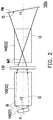
- FIG. 1 to FIG. 3 are schematic diagrams of puddle lamps according to different embodiments of the invention.
- FIG. 4A is an image optical simulation diagram of a puddle lamp of a comparative embodiment.
- FIG. 4B to FIG. 4D are image optical simulation diagrams of the puddle lamps of the embodiments of FIG. 1 to FIG. 3 .
- FIG. 1 to FIG. 3 are schematic diagrams of puddle lamps according to different embodiments of the invention.
- the puddle lamp 100 includes a light source 110 , a lens set 120 , a projection film 130 and a projection lens 140 .
- the above components are described in detail below.
- the puddle lamp 100 only includes one light source 110 , and the light source 110 has an optical axis I 1 (i.e. first optical axis) and is composed of a single light-emitting body.
- the light-emitting body is, for example, a Light-Emitting Diode (LED) module that is packaged in various types, a laser diode module that is packaged in various types, a fluorescent lamp, or an electric heating light-emitting element (Lamp), etc., which may output an illumination beam IB.
- the aforementioned package may include only a single light-emitting chip or a plurality of light-emitting chips.
- the light source 110 only includes a white LED module packaged by SMD technology, and the aforementioned white LED module includes a plurality of LED chips with a total rated power of 2 watts or less.
- the lens set 120 may be used for receiving and collimating light in the system, which includes at least one or more lenses.
- the lens in the lens set 120 can be viewed as relay lens.
- the lens set 120 has an optical axis I 2 (i.e. second optical axis), and includes at least one collimating lens, which may collimate light incident to the collimating lens along a direction of the optical axis I 2 .
- the lens set 120 only includes one lens.
- the lens set 120 may include a plurality of lenses, and the number of the lenses is not limited by the invention.
- the projection film 130 may be a device or element adapted to convert the illumination beam IB into an image beam IMB with a fixed and unchangeable pattern, and includes a transmissive fixed image layer.
- the projection film 130 may be a transparent film carrying a specific pattern or a sheet metal member (for example, a metal plate or a plastic plate, etc.) having light transmitting portions of a specific pattern (for example, hollowed parts or glass, etc.), and none electric power is consumed during a process that the projection film 130 converts the illumination beam IB into the image beam IMB.
- the projector 130 is not a light valve that needs to consume power such as DMD, LCD, or LCOS, etc.
- the projection film 130 is a transparent film carrying a specific pattern, and when the light passes through the specific pattern, the light is partially absorbed, blocked or reflected, and a part of the light is allowed to pass through to form a pattern.
- a filter and the projector film 130 have the same functions and characteristics, except that it specifically refers to the projection film 130 that forms a pattern by filtering a part of the light.
- the projection lens 140 includes a plurality of lenses having refractive powers.
- the projection lens 140 has an optical axis I 3 , and a front lens set and a rear lens set separated by an aperture are located on the optical axis I 3 , and the front lens set and the rear lens set respectively include one or more lenses, for example, a combination of one or more lenses with refractive powers.
- Each of the lenses may be any one of a biconcave lens, a biconvex lens, a concavo-convex lens, a convexo-concave lens, a plano-convex lens and a plano-concave lens.
- the aperture may also be configured at a light input end or the light output end of the projection lens 140 , and the pattern and type of the projection lens 140 are not limited by the invention.
- the lens set 120 is disposed at a light path downstream side of the light source 110 .
- the projection film 130 is disposed at a light path downstream side of the lens set 120 .
- the projection lens 140 is disposed at a light path downstream side of the projection film 130 . Since light is transmitted from an upstream side to the downstream side along the light path, the light path downstream side of a device may be regarded as a light path portion after the light passes through the device.
- the light path downstream side of the light source 110 the light path after the light is emitted from the light source 110 is all referred to as the light path downstream side of the light source 110 , and the lens set 120 , the projection film 130 , the projection lens 140 are all located at the light path downstream side of the light source 110 , and the projection film 130 and the projection lens 140 are all located at the light path downstream side of the lens set 120 , and the others may be deduced by analogy.
- the optical axis I 1 of the light source 110 , the optical axis I 2 of the lens set 120 , and the optical axis I 3 of the projection lens 140 are substantially parallel, and the optical axis I 2 of the lens set 120 and the optical axis I 3 of the projection lens 140 are coincided with each other (i.e.
- the lens set 120 and the projection lens 140 are optically coaxial), but the light source 110 and the lens set 120 has a non-zero offset OS in a direction D perpendicular to the optical axis I 2 , where an absolute value of the offset OS may be within a range of 0.1 mm or more and 0.3, 0.6, 1, 3, 5, 10 mm or less and does not include 0 mm, i.e., the optical axis I 1 of the light source 110 and the optical axis I 2 of the lens set 120 do not coincide with each other.
- the offset OS when the offset OS is positive, it represents that the optical axis I 1 of the light source 110 has the offset OS in an opposite direction of the direction D compared to the optical axis I 2 of the lens set 120 . Conversely, when the offset OS is negative, it represents that the optical axis I 1 of the light source 110 has the non-zero offset OS in the direction D compared to the optical axis I 3 of the projection lens 140 .
- the offset OS is a shift by 0.25 mm in the direction D, i.e. the offset OS is ⁇ 0.25 mm.
- the lens set 120 and the projection lens 140 are then regarded as another optical subsystem S 2 , and the optical axis I 1 of the optical subsystem S 1 has the non-zero offset OS in the direction D or the opposite direction of the direction D compared with the optical axis I 2 (or I 3 ) of the optical subsystem S 2 .
- the illumination beam IB emitted by the light source 110 is transmitted to the lens set 120 , after the lens set 120 collimates the illumination beam IB, the illumination light IB is further transmitted to the projection film 130 .
- the projection film 130 converts the illumination beam IB into the image beam IMB
- the projection lens 140 projects the image beam IMB onto a surface of a projection medium PM, and in the embodiment, the projection medium PM is the ground, but the invention is not limited thereto.
- the surface of the projection medium PM may be regarded as an image plane IS. In the embodiment, in a reference plane (i.e. the plane shown in FIG.
- a non-zero included angle ⁇ 1 (or referred to as a first included angle) is included between the optical axis I 3 of the projection lens 140 and the image plane IS, and the offset OS is inversely proportional to the included angle ⁇ 1 , i.e., the larger the absolute value of the offset OS is, the smaller the absolute value of the corresponding included angle ⁇ 1 is, and the better the uniformity improvement effect is.
- the included angle ⁇ 1 is an acute angle less than 90 degrees formed with the optical axis.
- the optical axis I 3 of the projection lens 140 intersects with the image plane IS to form a reference point RP, and the reference plane is determined by the optical axis I 3 of the projection lens 140 , a normal vector on the reference point RP of the image plane IS, and the first reference point RP.
- the reference plane includes the first, the second and the third optical axes I 1 , I 2 , I 3 .
- the puddle lamp 100 a of FIG. 2 is substantially similar to the puddle lamp of FIG. 1 , and a main difference therebetween is that in the puddle lamp 100 a , the optical axis I 1 of the light source 110 is not parallel with the optical axis I 3 of the projection lens 140 , and the optical axis I 2 of the lens set 120 and the optical axis I 3 of the projection lens 140 are still substantially parallel and coincided with each other (i.e. the lens set 120 and the projection lens 140 are optically coaxial).
- the optical axis I 1 of the light source 110 is tilted relative to the optical axis I 2 of the lens set 120 (or the optical axis I 3 of the projection lens 140 ), and in the reference plane, a non-zero included angle ⁇ 2 (or referred to as a second included angle) is included therebetween.
- the absolute value of the included angle ⁇ 2 may be 30, 20 or 10 degrees or less, and in the embodiment, the absolute value of the included angle ⁇ 2 is about 20 degrees.
- the lens set 120 and the projection lens 140 are then regarded as another optical subsystem S 2 , and the optical axis I 1 of the optical subsystem S 1 is tilted relative to the optical axis I 2 (or I 3 ) of the optical subsystem S 2 by an included angle ⁇ 2 .
- the optical axis I 1 of the light source 110 is rotated relative to the optical axis I 2 of the lens set 120 by the included angle ⁇ 2 in a clockwise direction.
- the included angle ⁇ 2 is negative, it represents that the optical axis I 1 of the light source 110 is rotated relative to the optical axis I 2 of the lens set 120 by the included angle ⁇ 2 in an anticlockwise direction.
- the optical axis I 1 of the light source 110 is rotated relative to the optical axis I 2 of the lens set 120 by an included angle of 20 degrees in the anticlockwise direction, i.e. included angle ⁇ 2 is ⁇ 20 degrees.
- the puddle lamp 100 b of FIG. 3 is substantially similar to the puddle lamp of FIG. 1 , and a main difference therebetween is that in the puddle lamp 100 b , the optical axis I 1 of the light source 110 is not parallel with the optical axis I 3 of the projection lens 140 , the optical axis I 2 of the lens set 120 is not parallel with the optical axis I 3 of the projection lens 140 , but the optical axis I 1 of the light source 110 and the optical axis I 2 of the lens set 120 are still substantially parallel and coincided (i.e. the light source 110 and the lens set 120 are optically coaxial).
- the projection lens 140 is then regarded as another optical subsystem S 2 .
- the optical axis I 1 (or I 2 ) of the optical subsystem S 1 is tilted relative to the optical axis I 3 of the optical subsystem S 2 by an absolute value of an included angle ⁇ 3 that is less than 30, 20, 10 or 5 degrees. In the embodiment, the included angle ⁇ 3 is about 3 degrees.
- FIG. 4A is an image optical simulation diagram of a puddle lamp of a comparative embodiment.
- FIG. 4B to FIG. 4D are image optical simulation diagrams of the puddle lamps of the embodiments of FIG. 1 to FIG. 3 .
- an image light intensity distribution diagram and a luminance distribution diagram in different directions D 1 and D 2 are respectively included.
- a darker part is the part with stronger light intensity, while a lighter part is the part with smaller light intensity.
- optical effects of the puddle lamps 100 , 100 a and 100 b in the above embodiments are described according to FIG. 4A to FIG. 4D .
- the puddle lamp of the comparative embodiment (not shown) is substantially similar to the puddle lamp of the embodiment, and a main difference therebetween is that the optical axis of the light source and the optical axis of the lens set of the puddle lamp of the comparative embodiment do not have the offset, and an included angle between the optical axis of the light source, the optical axis of the lens set and the optical axis of the projection lens is 0 degrees (or 180 degrees), i.e. the optical axes of the light source, the lens set and the projection lens are parallel and coincided with each other (i.e. the light source, the lens set and the projection lens are optically coaxial).
- the optical axes I 1 and I 2 of the light source 110 , the lens set 120 are substantially parallel, and the optical axis I 1 of the light source 110 and the optical axis I 2 of the lens set 120 have the non-zero offset OS in the direction D parallel to the optical axis.
- the optical axis I 1 of the light source 110 is not parallel with the optical axis I 3 of the projection lens 140 , where in the puddle lamp 100 a of FIG.
- the optical axis I 1 of the light source 110 and the optical axis I 2 of the lens set 120 are designed to be tilted with each other to include a non-zero included angle ⁇ 2 therebetween.
- the optical axis I 1 of the light source 110 and the optical axis I 2 of the lens set 120 are designed to be parallel and coincided but include the non-zero included angle ⁇ 3 with the optical axis I 3 of the projection lens 140 .
- geometric asymmetry is introduced into the optical systems of the puddle lamps 100 , 100 a and 100 b , and when the illumination beam IB passes through the lens set 120 and the projection lens 140 with the different configurations described above, even if the distances between the puddle lamps 100 , 100 a , 100 b and the projection medium PM are different (i.e., distance asymmetry), through the above introduced geometric asymmetry, a larger proportion of the illumination beam IB may be directed to the projection medium PM at a greater distance, while a smaller proportion of the illumination beam IB may be directed to the projection medium PM at a closer distance, to cause optical asymmetry, which makes it possible to project an image with a uniform brightness on the projection medium PM.
- optical asymmetry is introduced in the form of an offset or tilt, thereby balancing the asymmetry of the distances between the puddle lamps 100 , 100 a , 100 b and the projection medium PM, so as to project images with a uniform brightness.
- the optical axes of the light source and the lens set are substantially parallel, and the optical axis of the light source and the optical axis of the lens set have an offset in a direction parallel to the optical axis.
- the optical axis of the light source is not parallel with the optical axis of the lens set and the optical axis of the projection lens. Even if the distances between the puddle lamp and the projection medium are different, through the above configuration, the puddle lamp may project an image with a uniform brightness on the projection medium.
Landscapes
- Engineering & Computer Science (AREA)
- Mechanical Engineering (AREA)
- General Engineering & Computer Science (AREA)
- Physics & Mathematics (AREA)
- Microelectronics & Electronic Packaging (AREA)
- Optics & Photonics (AREA)
- General Physics & Mathematics (AREA)
- Non-Portable Lighting Devices Or Systems Thereof (AREA)
- Projection Apparatus (AREA)
Abstract
Description
Claims (20)
Applications Claiming Priority (2)
| Application Number | Priority Date | Filing Date | Title |
|---|---|---|---|
| TW108141089A TWI764063B (en) | 2019-11-13 | 2019-11-13 | Puddle lamp |
| TW108141089 | 2019-11-13 |
Publications (2)
| Publication Number | Publication Date |
|---|---|
| US20210140603A1 US20210140603A1 (en) | 2021-05-13 |
| US11215337B2 true US11215337B2 (en) | 2022-01-04 |
Family
ID=75846664
Family Applications (1)
| Application Number | Title | Priority Date | Filing Date |
|---|---|---|---|
| US16/916,172 Expired - Fee Related US11215337B2 (en) | 2019-11-13 | 2020-06-30 | Puddle lamp |
Country Status (2)
| Country | Link |
|---|---|
| US (1) | US11215337B2 (en) |
| TW (1) | TWI764063B (en) |
Cited By (3)
| Publication number | Priority date | Publication date | Assignee | Title |
|---|---|---|---|---|
| US20210387565A1 (en) * | 2020-06-11 | 2021-12-16 | Hyundai Mobis Co., Ltd. | Camera-puddle lamp integrated apparatus and side mirror including the same |
| US20210387564A1 (en) * | 2020-06-11 | 2021-12-16 | Hyundai Mobis Co., Ltd. | Camera-puddle lamp integrated apparatus and side mirror including the same |
| US12320486B2 (en) | 2021-07-12 | 2025-06-03 | Valeo Vision | Light module including an element with variable light transmission rate |
Families Citing this family (1)
| Publication number | Priority date | Publication date | Assignee | Title |
|---|---|---|---|---|
| CN115059898B (en) * | 2022-05-13 | 2024-04-12 | 北京一数科技有限公司 | Automobile projection device |
Citations (10)
| Publication number | Priority date | Publication date | Assignee | Title |
|---|---|---|---|---|
| US8007133B2 (en) * | 2007-12-28 | 2011-08-30 | Seiko Epson Corporation | Light source device and projector |
| US20160356444A1 (en) * | 2015-06-08 | 2016-12-08 | Stanley Electric Co., Ltd. | Vehicle lighting fixture |
| US9686517B2 (en) * | 2014-12-15 | 2017-06-20 | Test Research, Inc. | Optical system and image compensating method of optical apparatus |
| US20190270403A1 (en) * | 2016-11-28 | 2019-09-05 | Magna Mirrors Of America, Inc. | Exterior illumination and icon projection module for vehicle |
| US20190324362A1 (en) * | 2018-04-19 | 2019-10-24 | Ford Global Technologies, Llc | Vehicle puddle lamp assembly |
| US20190368689A1 (en) * | 2018-06-05 | 2019-12-05 | Motherson Innovations Company Limited | Light system with a single one-part lens |
| US20200088379A1 (en) * | 2016-12-28 | 2020-03-19 | Dai Nippon Printing Co., Ltd. | Illumination device |
| US20200173625A1 (en) * | 2017-07-27 | 2020-06-04 | SMR Patents S.à.r.l. | Projection device, rear-view device and motor vehicle |
| US20200183328A1 (en) * | 2016-09-13 | 2020-06-11 | Volkswagen Aktiengesellschaft | Method And Apparatus For Generating Image Effects In The Interior Or Outside Of A Vehicle |
| US20200290516A1 (en) * | 2017-04-20 | 2020-09-17 | Motherson Innovations Company Limited | Combined approach lamp and logo lamp |
Family Cites Families (2)
| Publication number | Priority date | Publication date | Assignee | Title |
|---|---|---|---|---|
| EP3434966B1 (en) * | 2016-03-24 | 2023-02-22 | Koito Manufacturing Co., Ltd. | Vehicle lamp and vehicle provided with it |
| CN208703846U (en) * | 2018-07-29 | 2019-04-05 | 深圳市睿光达光电有限公司 | Vehicle body identifies projection lamp |
-
2019
- 2019-11-13 TW TW108141089A patent/TWI764063B/en active
-
2020
- 2020-06-30 US US16/916,172 patent/US11215337B2/en not_active Expired - Fee Related
Patent Citations (10)
| Publication number | Priority date | Publication date | Assignee | Title |
|---|---|---|---|---|
| US8007133B2 (en) * | 2007-12-28 | 2011-08-30 | Seiko Epson Corporation | Light source device and projector |
| US9686517B2 (en) * | 2014-12-15 | 2017-06-20 | Test Research, Inc. | Optical system and image compensating method of optical apparatus |
| US20160356444A1 (en) * | 2015-06-08 | 2016-12-08 | Stanley Electric Co., Ltd. | Vehicle lighting fixture |
| US20200183328A1 (en) * | 2016-09-13 | 2020-06-11 | Volkswagen Aktiengesellschaft | Method And Apparatus For Generating Image Effects In The Interior Or Outside Of A Vehicle |
| US20190270403A1 (en) * | 2016-11-28 | 2019-09-05 | Magna Mirrors Of America, Inc. | Exterior illumination and icon projection module for vehicle |
| US20200088379A1 (en) * | 2016-12-28 | 2020-03-19 | Dai Nippon Printing Co., Ltd. | Illumination device |
| US20200290516A1 (en) * | 2017-04-20 | 2020-09-17 | Motherson Innovations Company Limited | Combined approach lamp and logo lamp |
| US20200173625A1 (en) * | 2017-07-27 | 2020-06-04 | SMR Patents S.à.r.l. | Projection device, rear-view device and motor vehicle |
| US20190324362A1 (en) * | 2018-04-19 | 2019-10-24 | Ford Global Technologies, Llc | Vehicle puddle lamp assembly |
| US20190368689A1 (en) * | 2018-06-05 | 2019-12-05 | Motherson Innovations Company Limited | Light system with a single one-part lens |
Cited By (5)
| Publication number | Priority date | Publication date | Assignee | Title |
|---|---|---|---|---|
| US20210387565A1 (en) * | 2020-06-11 | 2021-12-16 | Hyundai Mobis Co., Ltd. | Camera-puddle lamp integrated apparatus and side mirror including the same |
| US20210387564A1 (en) * | 2020-06-11 | 2021-12-16 | Hyundai Mobis Co., Ltd. | Camera-puddle lamp integrated apparatus and side mirror including the same |
| US11603032B2 (en) * | 2020-06-11 | 2023-03-14 | Hyundai Mobis Co., Ltd. | Camera-puddle lamp integrated apparatus and side mirror including the same |
| US11780360B2 (en) * | 2020-06-11 | 2023-10-10 | Hyundai Mobis Co., Ltd. | Camera-puddle lamp integrated apparatus and side mirror including the same |
| US12320486B2 (en) | 2021-07-12 | 2025-06-03 | Valeo Vision | Light module including an element with variable light transmission rate |
Also Published As
| Publication number | Publication date |
|---|---|
| TW202119868A (en) | 2021-05-16 |
| US20210140603A1 (en) | 2021-05-13 |
| TWI764063B (en) | 2022-05-11 |
Similar Documents
| Publication | Publication Date | Title |
|---|---|---|
| US11215337B2 (en) | Puddle lamp | |
| JP6506885B2 (en) | Lighting device of light projector for motor vehicle | |
| CN112135998B (en) | Vehicle lamp | |
| US9645480B2 (en) | Light source module and projection apparatus having the same | |
| US8550676B2 (en) | Vehicle light | |
| US20220324373A1 (en) | Low beam optical module, low beam illumination module, vehicle lamp and vehicle | |
| US20200256537A1 (en) | Vehicular lighting fixture | |
| US10415784B2 (en) | Lighting module with chromatism correction | |
| US12435856B2 (en) | Vehicle lamp having a lens with a functional layer and a color layer | |
| CN105318281B (en) | Laser optical system for a headlamp | |
| TWI571592B (en) | High contrast and miniature headlamp | |
| CN101169576B (en) | Projection device and its internal total reflection prism | |
| US12104761B2 (en) | Vehicle lamp | |
| US20220009409A1 (en) | Vehicle Light and Vehicle Including a Vehicle Light | |
| US20250147399A1 (en) | Optical member, light source device, and head-up display | |
| US10781988B2 (en) | Vehicular lamp | |
| WO2024148842A1 (en) | Illumination device and vehicle lamp | |
| CN112856329B (en) | Welcome light | |
| US10794562B2 (en) | Vehicle optical system and vehicle lamp using the same | |
| KR101906526B1 (en) | Integrated optical system of lighting device for vehicle | |
| CN105182673A (en) | Projector | |
| CN111457314A (en) | A Novel Automotive Lighting Optical System Based on Double Free-form Surface Lens Group | |
| US20250155788A1 (en) | Illumination system and projection device | |
| JP2016115583A (en) | Vehicular lighting unit | |
| TWI731332B (en) | Projection device and fabrication method thereof |
Legal Events
| Date | Code | Title | Description |
|---|---|---|---|
| FEPP | Fee payment procedure |
Free format text: ENTITY STATUS SET TO UNDISCOUNTED (ORIGINAL EVENT CODE: BIG.); ENTITY STATUS OF PATENT OWNER: LARGE ENTITY |
|
| AS | Assignment |
Owner name: YOUNG OPTICS INC., TAIWAN Free format text: ASSIGNMENT OF ASSIGNORS INTEREST;ASSIGNORS:LEE, CHIA-YUN;CHEN, S-WEI;REEL/FRAME:053114/0648 Effective date: 20200618 |
|
| STPP | Information on status: patent application and granting procedure in general |
Free format text: DOCKETED NEW CASE - READY FOR EXAMINATION |
|
| STPP | Information on status: patent application and granting procedure in general |
Free format text: NOTICE OF ALLOWANCE MAILED -- APPLICATION RECEIVED IN OFFICE OF PUBLICATIONS |
|
| STPP | Information on status: patent application and granting procedure in general |
Free format text: PUBLICATIONS -- ISSUE FEE PAYMENT RECEIVED |
|
| STPP | Information on status: patent application and granting procedure in general |
Free format text: PUBLICATIONS -- ISSUE FEE PAYMENT VERIFIED |
|
| STCF | Information on status: patent grant |
Free format text: PATENTED CASE |
|
| FEPP | Fee payment procedure |
Free format text: MAINTENANCE FEE REMINDER MAILED (ORIGINAL EVENT CODE: REM.); ENTITY STATUS OF PATENT OWNER: LARGE ENTITY |
|
| LAPS | Lapse for failure to pay maintenance fees |
Free format text: PATENT EXPIRED FOR FAILURE TO PAY MAINTENANCE FEES (ORIGINAL EVENT CODE: EXP.); ENTITY STATUS OF PATENT OWNER: LARGE ENTITY |
|
| STCH | Information on status: patent discontinuation |
Free format text: PATENT EXPIRED DUE TO NONPAYMENT OF MAINTENANCE FEES UNDER 37 CFR 1.362 |
|
| FP | Lapsed due to failure to pay maintenance fee |
Effective date: 20260104 |