US11214985B1 - Electro-mechanical latch with cocking mechanism - Google Patents
Electro-mechanical latch with cocking mechanism Download PDFInfo
- Publication number
- US11214985B1 US11214985B1 US15/883,907 US201815883907A US11214985B1 US 11214985 B1 US11214985 B1 US 11214985B1 US 201815883907 A US201815883907 A US 201815883907A US 11214985 B1 US11214985 B1 US 11214985B1
- Authority
- US
- United States
- Prior art keywords
- plunger
- ball
- lever arm
- housing
- lever
- Prior art date
- Legal status (The legal status is an assumption and is not a legal conclusion. Google has not performed a legal analysis and makes no representation as to the accuracy of the status listed.)
- Active, expires
Links
Images


Classifications
-
- E—FIXED CONSTRUCTIONS
- E05—LOCKS; KEYS; WINDOW OR DOOR FITTINGS; SAFES
- E05B—LOCKS; ACCESSORIES THEREFOR; HANDCUFFS
- E05B47/00—Operating or controlling locks or other fastening devices by electric or magnetic means
- E05B47/06—Controlling mechanically-operated bolts by electro-magnetically-operated detents
-
- E—FIXED CONSTRUCTIONS
- E05—LOCKS; KEYS; WINDOW OR DOOR FITTINGS; SAFES
- E05B—LOCKS; ACCESSORIES THEREFOR; HANDCUFFS
- E05B47/00—Operating or controlling locks or other fastening devices by electric or magnetic means
- E05B47/0001—Operating or controlling locks or other fastening devices by electric or magnetic means with electric actuators; Constructional features thereof
- E05B47/0002—Operating or controlling locks or other fastening devices by electric or magnetic means with electric actuators; Constructional features thereof with electromagnets
- E05B47/0003—Operating or controlling locks or other fastening devices by electric or magnetic means with electric actuators; Constructional features thereof with electromagnets having a movable core
- E05B47/0005—Operating or controlling locks or other fastening devices by electric or magnetic means with electric actuators; Constructional features thereof with electromagnets having a movable core said core being rotary movable
-
- E—FIXED CONSTRUCTIONS
- E05—LOCKS; KEYS; WINDOW OR DOOR FITTINGS; SAFES
- E05B—LOCKS; ACCESSORIES THEREFOR; HANDCUFFS
- E05B17/00—Accessories in connection with locks
- E05B17/20—Means independent of the locking mechanism for preventing unauthorised opening, e.g. for securing the bolt in the fastening position
- E05B17/2007—Securing, deadlocking or "dogging" the bolt in the fastening position
- E05B17/2011—Securing, deadlocking or "dogging" the bolt in the fastening position using balls or the like cooperating with notches
-
- Y—GENERAL TAGGING OF NEW TECHNOLOGICAL DEVELOPMENTS; GENERAL TAGGING OF CROSS-SECTIONAL TECHNOLOGIES SPANNING OVER SEVERAL SECTIONS OF THE IPC; TECHNICAL SUBJECTS COVERED BY FORMER USPC CROSS-REFERENCE ART COLLECTIONS [XRACs] AND DIGESTS
- Y10—TECHNICAL SUBJECTS COVERED BY FORMER USPC
- Y10T—TECHNICAL SUBJECTS COVERED BY FORMER US CLASSIFICATION
- Y10T292/00—Closure fasteners
- Y10T292/14—Ball
Definitions
- the present invention relates to electro-mechanical ball latches, and more particularly to a spring loaded electro-mechanical ball latch having a cocking mechanism.
- Electro-mechanical ball latches are known in the prior art.
- an improved ball-latch mechanism comprising: a housing ( 22 ); a plunger ( 17 ) supported in the housing and having a ball bearing surface ( 23 ); the plunger disposed relative to the housing such that the plunger may be moved axially along a longitudinal axis ( 19 ) in a linear range of motion ( 37 ) from a loaded position ( FIG. 5 ) to an extended position ( FIG.
- a trigger 16 supported in the housing and having a ball bearing surface ( 24 ); the trigger disposed relative to the plunger such that the trigger may be rotated about the longitudinal axis from a latched position ( FIG. 5 ) to an unlatched position ( FIG. 2 ); a ball bearing ( 20 ) located in contacting relation with the ball bearing surface of the trigger, the ball bearing being radially movable relative to the longitudinal axis between a first position ( FIG. 5 ), wherein the ball bearing interferes with the bearing surface of the plunger when the trigger is in the latched position and the plunger is in the loaded position, and a second position ( FIG.
- a bias element biasing the plunger axially from the loaded position
- a cocking mechanism supported in the housing and comprising a lever arm ( 28 ) having a plunger bearing surface ( 29 ) and a torque receiving surface ( 30 ), the lever arm being rotatable about a lever axis ( 21 ) substantially perpendicular to the longitudinal axis; and the lever arm rotatable about the lever axis from a retracted position ( FIG.
- the plunger bearing surface of the lever arm is outside of the range of motion of the plunger, and a cocked position ( FIG. 4 ), wherein the plunger bearing surface of the lever arm bears against the plunger and the plunger is in the loaded position; whereby the plunger may be forced to the loaded position by the lever arm by application of torque to the torque receiving surface; and whereby the trigger may be rotated to the latched position with the ball bearing in the first position to latch the plunger in the loaded position.
- the ball-latch mechanism may further comprise an actuator ( 31 ) configured to rotate the trigger relative to the plunger to the unlatched position, and the actuator may comprise a solenoid.
- the bias element may comprise a coil spring.
- the torque receiving surface may comprise a hex nut.
- the lever axis may not intersect the longitudinal axis of the plunger and the lever axis may be closest to the longitudinal axis between the loaded position and the extended position of the plunger.
- the cocking mechanism may comprise a second bias element ( 32 ) biasing the lever arm to the retracted position within the housing, and the second bias element may comprise a torsional spring.
- the cocking mechanism may comprise a clevis member ( 33 ) in the housing having two openings and the lever arm may comprise a shaft ( 34 ) orientated about the lever axis and extending through the openings in the clevis member.
- the torque receiving surface of the lever arm may comprise a nut at a first end of the shaft.
- the plunger bearing surface of the lever arm may comprise a roller bearing.
- FIG. 1 is a perspective view of a first embodiment of an improved ball-latch mechanism.
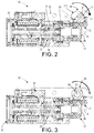
- FIG. 2 is a vertical longitudinal sectional view of the mechanism shown in FIG. 1 , in a trigger unlatched position, plunger extended position and a lever arm retracted position.
- FIG. 3 is a view of the mechanism shown in FIG. 2 in a position in which the lever arm engages the plunger shown in FIG. 2 .
- FIG. 4 is a view of the mechanism shown in FIG. 2 in a trigger latched position, plunger loaded position and lever arm cocked position.
- FIG. 5 is a view of the mechanism shown in FIG. 2 in a trigger latched position, plunger loaded position and lever arm retracted position.
- the terms “horizontal”, “vertical”, “left”, “right”, “up” and “down”, as well as adjectival and adverbial derivatives thereof simply refer to the orientation of the illustrated structure as the particular drawing figure faces the reader.
- the terms “inwardly” and “outwardly” generally refer to the orientation of a surface relative to its axis of elongation, or axis of rotation, as appropriate.
- Ball latch 15 generally includes housing 22 supporting spring loaded outer tubular plunger 17 , inner cylindrical trigger 16 , cage 18 concentrically located between tubular plunger 17 and inner trigger 16 , rotary solenoid 31 and cocking mechanism 26 .
- Cage 18 has a plurality of circumferentially arranged apertures for receiving spherical balls 20 .
- An inner wall of plunger 17 has grooves that may be aligned with the apertures of cage 18 for receiving balls 20 .
- an outer wall of inner trigger 16 has channels for receiving balls 20 .
- balls 20 are simultaneously disposed in the apertures of cage 18 and the grooves of outer tubular plunger 17 , thereby preventing any relative axial linear movement along axis 19 between the two.
- inner cylindrical trigger 16 is rotated by rotary solenoid 31 relative to cage 18 such that the channels of inner cylindrical trigger 16 are aligned with balls 20 .
- balls 20 are permitted to retract radially inward from the grooves of outer tubular plunger 17 below the outer surface of cage 18 and into the channels in inner cylindrical trigger 16 , as shown in FIG. 2 , such that outer tubular plunger 17 is released and is thereby free to move axially past balls 20 .
- a large axial load is applied to outer tubular plunger 17 by coil spring 25 in the latched condition which, upon unlatching, causes an immediate and powerful axial movement of outer tubular plunger 17 and its end face 36 to the right along axis 19 with respect to cage 18 and housing 22 .
- outer plunger 17 is spring-loaded by spring 25 and when released will move rapidly axially from left to right to the extended position, shown in FIGS. 2 and 3 .
- plunger 17 In order to place the latch in the latched or cocked position, shown in FIGS. 4 and 5 , plunger 17 must be forced axially to the left against the force of coil spring 25 until the grooves in plunger 17 are positioned over the slots of cage 18 . Trigger 16 is then rotated by rotary solenoid 31 until the channels of inner cylindrical trigger 16 and the slots of cage 18 are out of alignment, forcing latch balls 20 by cam action into contact with the grooves in plunger 17 , thereby locking plunger 17 in the latched or cocked position. In this position, plunger 17 is prevented from moving to the right due to the interference caused by latch balls 20 protruding through cage 18 and engaging the groves in plunger 17 .
- cocking mechanism 26 is used to push plunger 17 to the left against coiled spring 25 to the loaded position shown in FIG. 4 .
- cocking mechanism 26 comprises two outer cocking nuts 30 a and 30 b on either end of shaft 34 , which is supported by clevis member 33 and rotatable relative to housing 22 and clevis 33 about lever axis 21 , lever arm 28 extending from rotating shaft 34 and having roller bearing end 29 , and lever return spring 32 configured to bias lever 28 to rotate in the counter clockwise direction about lever axis 21 absent a counter force.
- Cocking mechanism 26 is integrated into the unit and shares the same housing 22 as solenoid 31 and ball latch components 16 , 18 , 20 and 31 .
- Cocking nuts 30 A and 30 B are positioned outside of unit housing 22 so that they are easily accessible on either side and may be rotated with a conventional wrench from either side.
- Lever axis 21 is substantially perpendicular to longitudinal axis 19 of plunger 17 . As shown, lever axis 21 is in a horizontal plane above the horizontal plane of longitudinal axis 19 such that lever axis 21 and longitudinal axis 19 do not intersect. As shown in FIG. 5 , end face 36 of plunger 17 has operational range of motion 37 along longitudinal axis 19 from its loaded position shown in FIG. 5 to its extended position shown in FIG. 2 . Lever axis 21 is in a vertical plane that intersect longitudinal axis 19 between the loaded position shown in FIG. 5 and the extended position shown in FIG. 2 , such that lever axis 21 is closest to longitudinal axis 19 between the loaded position and the extended position of end face 36 of plunger 17 .
- Torsional lever return spring 32 causes nut 30 A and lever arm 28 to rotate in the counterclockwise direction about lever axis 21 such that roller bearing 29 at the end of lever arm 28 is away from plunger 17 and lever arm 28 is retracted into corresponding recess 35 in housing 22 .
- cocking mechanism 16 has a low-profile so that it fits into the space available and such that lever arm 28 and roller bearing 29 are out of the way of the range of motion of plunger 17 once ball latch mechanism 15 is in the latched position. In the retracted position of FIG. 2 , bearing surface 29 of lever arm 28 is outside of the range of motion of plunger 17 .
- lever 28 that pushes plunger 17 back into the latched position retracts into recess 35 in housing 22 of cocking mechanism 26 .
- Plunger 17 may be forced to the loaded position by lever arm 28 by application of torque to hex nut 30 A and/or 30 B and trigger 16 may then be rotated to the latched position with ball bearings 20 in position to latch plunger 17 in the loaded position
- Cocking mechanism 26 provides a number of benefits. Due to the mechanical advantage of lever arm 28 , less force is required to cock or latch the ball latch. Mechanism 26 allows the ball latch to be cocked using a standard wrench or driver with about 4 pounds of force instead of the 30 to 32 pounds of force presently required without such mechanism. Mechanism 26 has a low profile and is integrated into solenoid unit housing 22 and is moved out of the way once the ball latch is cocked.
Landscapes
- Physics & Mathematics (AREA)
- Electromagnetism (AREA)
- Pinball Game Machines (AREA)
Abstract
A ball-latch mechanism comprising a plunger supported in a housing and linearly movable from a loaded to an extended position, a trigger rotatable from a latched position, which interferes with linear movement of the plunger, to an unlatched position, which permits linear movement of the plunger from the loaded position, a bias element biasing the plunger from the loaded position, a cocking mechanism comprising a lever arm rotatable about a lever axis from a retracted position within the housing, wherein a bearing surface of the lever arm is outside of a range of motion of the plunger, and a cocked position, wherein the bearing surface of the lever arm bears against the plunger and the plunger is in the loaded position, whereby the plunger may be forced to the loaded position by the lever arm by application of torque to a torque receiving surface of the lever arm.
Description
The present invention relates to electro-mechanical ball latches, and more particularly to a spring loaded electro-mechanical ball latch having a cocking mechanism.
Electro-mechanical ball latches are known in the prior art. U.S. Pat. No. 5,428,873, entitled “Ball Latch Mechanism,” the entire contents of which is incorporated herein by reference, describes such a latch.
With parenthetical reference to corresponding parts, portions or surfaces of the disclosed embodiment, merely for the purposes of illustration and not by way of limitation, an improved ball-latch mechanism (15) is provided comprising: a housing (22); a plunger (17) supported in the housing and having a ball bearing surface (23); the plunger disposed relative to the housing such that the plunger may be moved axially along a longitudinal axis (19) in a linear range of motion (37) from a loaded position (FIG. 5 ) to an extended position (FIG. 2 ); a trigger 16) supported in the housing and having a ball bearing surface (24); the trigger disposed relative to the plunger such that the trigger may be rotated about the longitudinal axis from a latched position (FIG. 5 ) to an unlatched position (FIG. 2 ); a ball bearing (20) located in contacting relation with the ball bearing surface of the trigger, the ball bearing being radially movable relative to the longitudinal axis between a first position (FIG. 5 ), wherein the ball bearing interferes with the bearing surface of the plunger when the trigger is in the latched position and the plunger is in the loaded position, and a second position (FIG. 2 ), wherein the ball bearing is retracted when the trigger is in the unlatched position permitting axial movement of the plunger from the loaded position; a bias element (25) biasing the plunger axially from the loaded position; a cocking mechanism (26) supported in the housing and comprising a lever arm (28) having a plunger bearing surface (29) and a torque receiving surface (30), the lever arm being rotatable about a lever axis (21) substantially perpendicular to the longitudinal axis; and the lever arm rotatable about the lever axis from a retracted position (FIG. 2 ) within the housing, wherein the plunger bearing surface of the lever arm is outside of the range of motion of the plunger, and a cocked position (FIG. 4 ), wherein the plunger bearing surface of the lever arm bears against the plunger and the plunger is in the loaded position; whereby the plunger may be forced to the loaded position by the lever arm by application of torque to the torque receiving surface; and whereby the trigger may be rotated to the latched position with the ball bearing in the first position to latch the plunger in the loaded position.
The ball-latch mechanism may further comprise an actuator (31) configured to rotate the trigger relative to the plunger to the unlatched position, and the actuator may comprise a solenoid. The bias element may comprise a coil spring. The torque receiving surface may comprise a hex nut. The lever axis may not intersect the longitudinal axis of the plunger and the lever axis may be closest to the longitudinal axis between the loaded position and the extended position of the plunger. The cocking mechanism may comprise a second bias element (32) biasing the lever arm to the retracted position within the housing, and the second bias element may comprise a torsional spring. The cocking mechanism may comprise a clevis member (33) in the housing having two openings and the lever arm may comprise a shaft (34) orientated about the lever axis and extending through the openings in the clevis member. The torque receiving surface of the lever arm may comprise a nut at a first end of the shaft. The plunger bearing surface of the lever arm may comprise a roller bearing.
At the outset, it should be clearly understood that like reference numerals are intended to identify the same structural elements, portions or surfaces consistently throughout the several drawing figures, as such elements, portions or surfaces may be further described or explained by the entire written specification, of which this detailed description is an integral part. Unless otherwise indicated, the drawings are intended to be read (e.g., crosshatching, arrangement of parts, proportion, degree, etc.) together with the specification, and are to be considered a portion of the entire written description of this disclosure. As used in the following description, the terms “horizontal”, “vertical”, “left”, “right”, “up” and “down”, as well as adjectival and adverbial derivatives thereof (e.g., “horizontally”, “rightwardly”, “upwardly”, etc.), simply refer to the orientation of the illustrated structure as the particular drawing figure faces the reader. Similarly, the terms “inwardly” and “outwardly” generally refer to the orientation of a surface relative to its axis of elongation, or axis of rotation, as appropriate.
Referring now to FIGS. 1-5 , an improved ball latch is disclosed, a first embodiment of which is generally indicated at 15. Ball latch 15 generally includes housing 22 supporting spring loaded outer tubular plunger 17, inner cylindrical trigger 16, cage 18 concentrically located between tubular plunger 17 and inner trigger 16, rotary solenoid 31 and cocking mechanism 26.
In order to place the latch in the latched or cocked position, shown in FIGS. 4 and 5 , plunger 17 must be forced axially to the left against the force of coil spring 25 until the grooves in plunger 17 are positioned over the slots of cage 18. Trigger 16 is then rotated by rotary solenoid 31 until the channels of inner cylindrical trigger 16 and the slots of cage 18 are out of alignment, forcing latch balls 20 by cam action into contact with the grooves in plunger 17, thereby locking plunger 17 in the latched or cocked position. In this position, plunger 17 is prevented from moving to the right due to the interference caused by latch balls 20 protruding through cage 18 and engaging the groves in plunger 17.
As shown, cocking mechanism 26 is used to push plunger 17 to the left against coiled spring 25 to the loaded position shown in FIG. 4 . As shown, cocking mechanism 26 comprises two outer cocking nuts 30 a and 30 b on either end of shaft 34, which is supported by clevis member 33 and rotatable relative to housing 22 and clevis 33 about lever axis 21, lever arm 28 extending from rotating shaft 34 and having roller bearing end 29, and lever return spring 32 configured to bias lever 28 to rotate in the counter clockwise direction about lever axis 21 absent a counter force. Cocking mechanism 26 is integrated into the unit and shares the same housing 22 as solenoid 31 and ball latch components 16, 18, 20 and 31. Cocking nuts 30A and 30B are positioned outside of unit housing 22 so that they are easily accessible on either side and may be rotated with a conventional wrench from either side. Lever axis 21 is substantially perpendicular to longitudinal axis 19 of plunger 17. As shown, lever axis 21 is in a horizontal plane above the horizontal plane of longitudinal axis 19 such that lever axis 21 and longitudinal axis 19 do not intersect. As shown in FIG. 5 , end face 36 of plunger 17 has operational range of motion 37 along longitudinal axis 19 from its loaded position shown in FIG. 5 to its extended position shown in FIG. 2 . Lever axis 21 is in a vertical plane that intersect longitudinal axis 19 between the loaded position shown in FIG. 5 and the extended position shown in FIG. 2 , such that lever axis 21 is closest to longitudinal axis 19 between the loaded position and the extended position of end face 36 of plunger 17.
As shown, rotation of at least one of cocking nuts 30A or 30B in the clockwise direction about axis 21 causes roller bearing 29 at the end of lever arm 28 to bear against the right end face of plunger 17, as shown in FIG. 3 . Further rotation in the clockwise direction about axis 21 applies an axial force from right to left and compresses spring 25 and moves plunger 17 into its latched position, as shown in FIG. 4 . Trigger 16 is then rotated to hold plunger 17 in the latched position as described above. Once plunger 17 is in the latched position, nut 30A or 30B may be released. Torsional lever return spring 32 causes nut 30A and lever arm 28 to rotate in the counterclockwise direction about lever axis 21 such that roller bearing 29 at the end of lever arm 28 is away from plunger 17 and lever arm 28 is retracted into corresponding recess 35 in housing 22. As shown, cocking mechanism 16 has a low-profile so that it fits into the space available and such that lever arm 28 and roller bearing 29 are out of the way of the range of motion of plunger 17 once ball latch mechanism 15 is in the latched position. In the retracted position of FIG. 2 , bearing surface 29 of lever arm 28 is outside of the range of motion of plunger 17. Thus, lever 28 that pushes plunger 17 back into the latched position retracts into recess 35 in housing 22 of cocking mechanism 26. Plunger 17 may be forced to the loaded position by lever arm 28 by application of torque to hex nut 30A and/or 30B and trigger 16 may then be rotated to the latched position with ball bearings 20 in position to latch plunger 17 in the loaded position
The present invention contemplates that many changes and modifications may be made. Therefore, while forms of the improved ball latch have been shown and described, and a number of alternatives discussed, persons skilled in this art will readily appreciate that various additional changes and modifications may be made without departing from the scope of the invention, as defined and differentiated by the following claims.
Claims (9)
1. A ball-latch mechanism comprising:
a housing;
a plunger supported in said housing and having a ball bearing surface;
said plunger disposed relative to said housing such that said plunger is movable axially along a longitudinal axis in a linear range of motion from a loaded position to an extended position;
a trigger supported in said housing and having a ball bearing surface;
said trigger disposed relative to said plunger such that said trigger is rotatable about said longitudinal axis from a latched position to an unlatched position;
an actuator configured to rotate said trigger relative to said plunger to said unlatched position;
a ball bearing located in contacting relation with said ball bearing surface of said trigger, said ball bearing being radially movable relative to said longitudinal axis between a first position, wherein said ball bearing interferes with said bearing surface of said plunger when said trigger is in said latched position and said plunger is in said loaded position, and a second position, wherein said ball bearing is retracted when said trigger is in said unlatched position permitting axial movement of said plunger from said loaded position;
a first bias element biasing said plunger axially from said loaded position;
a cocking mechanism supported in said housing;
said cocking mechanism comprising a lever arm extending from a shaft orientated about a lever axis that is substantially perpendicular to said longitudinal axis, such that said lever arm operatively rotates about said lever axis relative to said housing with rotation of said shaft about said lever axis relative to said housing;
said lever arm having a plunger bearing surface and said shaft having a torque element defining a torque receiving surface;
said lever arm being rotatable about said lever axis by application of a torque to said torque receiving surface of said torque element of said cocking mechanism;
said cocking mechanism comprises a second bias element biasing said lever arm to said retracted position within said housing; and
said lever arm rotatable about said lever axis from a retracted position within said housing, wherein said plunger bearing surface of said lever arm is outside of said range of motion of said plunger, and a cocked position, wherein said plunger bearing surface of said lever arm bears against said plunger and said plunger is in said loaded position;
whereby said plunger is operatively configured to be forced to said loaded position by said plunger bearing surface of said lever arm by application of torque to said torque receiving surface of said cocking mechanism;
whereby said lever arm is operatively biased to said retracted position by said second bias element with release of said application of torque to said torque receiving surface of said torque element; and
whereby said trigger is operatively configured to be rotated to said latched position with said ball bearing in said first position to latch said plunger in said loaded position.
2. The ball-latch mechanism of claim 1 , wherein said actuator comprises a solenoid.
3. The ball-latch mechanism of claim 1 , wherein said first bias element comprises a coil spring.
4. The ball-latch mechanism of claim 1 , wherein said torque element comprises a hex nut.
5. The ball-latch mechanism of claim 1 , wherein said lever axis does not intersect said longitudinal axis of said plunger and said lever axis is closest to said longitudinal axis between said loaded position and said extended position of said plunger.
6. The ball-latch mechanism of claim 1 , wherein said second bias element comprises a torsional spring.
7. The ball-latch mechanism of claim 1 , wherein said cocking mechanism comprises a clevis member in said housing having two openings and said shaft orientated about said lever axis extends through said openings in said clevis member.
8. The ball-latch mechanism of claim 7 , wherein said torque element of said cocking mechanism comprises a nut at a first end of said shaft.
9. The ball-latch mechanism of claim 1 , wherein said plunger bearing surface of said lever arm comprises a roller bearing.
Priority Applications (1)
| Application Number | Priority Date | Filing Date | Title |
|---|---|---|---|
| US15/883,907 US11214985B1 (en) | 2017-02-08 | 2018-01-30 | Electro-mechanical latch with cocking mechanism |
Applications Claiming Priority (2)
| Application Number | Priority Date | Filing Date | Title |
|---|---|---|---|
| US201762456249P | 2017-02-08 | 2017-02-08 | |
| US15/883,907 US11214985B1 (en) | 2017-02-08 | 2018-01-30 | Electro-mechanical latch with cocking mechanism |
Publications (1)
| Publication Number | Publication Date |
|---|---|
| US11214985B1 true US11214985B1 (en) | 2022-01-04 |
Family
ID=79169639
Family Applications (1)
| Application Number | Title | Priority Date | Filing Date |
|---|---|---|---|
| US15/883,907 Active 2039-08-24 US11214985B1 (en) | 2017-02-08 | 2018-01-30 | Electro-mechanical latch with cocking mechanism |
Country Status (1)
| Country | Link |
|---|---|
| US (1) | US11214985B1 (en) |
Cited By (1)
| Publication number | Priority date | Publication date | Assignee | Title |
|---|---|---|---|---|
| US20200367669A1 (en) * | 2019-05-24 | 2020-11-26 | Fivetech Technology Inc. | Structure conducive to reduction of fastening element height |
Citations (23)
| Publication number | Priority date | Publication date | Assignee | Title |
|---|---|---|---|---|
| US1428566A (en) | 1920-12-03 | 1922-09-12 | Timmerman Frederic | Spring compressor |
| US2408560A (en) * | 1944-01-07 | 1946-10-01 | Warner L Keehn | Plate clamp |
| US2786383A (en) * | 1953-10-12 | 1957-03-26 | D W Price Corp | Cam operated ball detent clevis pin |
| US3011805A (en) * | 1958-06-04 | 1961-12-05 | Landor Inc | Pipe coupling with cam lever actuated latch for water test fixture |
| US3140721A (en) * | 1962-01-08 | 1964-07-14 | Timothy J Sullivan | Pressure and temperature protector for automatic full flow shut-off valve |
| US3214195A (en) * | 1962-05-25 | 1965-10-26 | Crawford Fitting Co | Coupling device for interconnecting multiple fluid lines |
| US3430305A (en) * | 1967-05-19 | 1969-03-04 | Ted Geffner | Releasable connectors |
| US3584544A (en) * | 1968-07-22 | 1971-06-15 | Robert W Haberman | Locking mechanism |
| US3730005A (en) * | 1971-12-20 | 1973-05-01 | Clare & Co C P | Electromechanical actuator |
| US3764172A (en) * | 1971-10-29 | 1973-10-09 | Cons Controls Corp | Latch assembly |
| US3980327A (en) | 1974-04-29 | 1976-09-14 | Avibank Mfg. Inc. | Latching mechanism |
| US4071271A (en) | 1975-07-29 | 1978-01-31 | R. Alkan & Cie. | Automatic release and ejection locking mechanism |
| US4512597A (en) * | 1982-07-12 | 1985-04-23 | Oy Wartsila Ab | Door lock |
| US4635452A (en) * | 1986-01-21 | 1987-01-13 | Olson Manufacturing Company | Double-acting barrel lock and key |
| US4890635A (en) | 1988-05-11 | 1990-01-02 | Gray Charles H Jr | Fire control valve |
| US4891994A (en) * | 1989-02-13 | 1990-01-09 | Plessey Incorporated | Linear electromechanical actuator |
| US5004003A (en) | 1988-05-11 | 1991-04-02 | Gray Charles H Jr | Fire control valve with pivotal latch |
| US5298088A (en) | 1993-03-12 | 1994-03-29 | Gray Charles H Jr | One-quarter turn ball valve closer |
| US5428873A (en) | 1993-04-29 | 1995-07-04 | Bw/Ip International, Inc. | Ball Latch mechanism |
| US20110277520A1 (en) | 2009-01-14 | 2011-11-17 | Martyn Sergeevich Nunuparov | Electronic device for a mechanical blocking. |
| US8083274B2 (en) | 2005-07-13 | 2011-12-27 | Artemis Intelligent Power Limited | Electro-magnetic release mechanism |
| US8220298B2 (en) | 2009-02-17 | 2012-07-17 | Channell Commercial Corporation | Self-latching locking assembly |
| US9297401B2 (en) * | 2013-10-18 | 2016-03-29 | Lisi Aerospace | Quick-release fastener |
-
2018
- 2018-01-30 US US15/883,907 patent/US11214985B1/en active Active
Patent Citations (23)
| Publication number | Priority date | Publication date | Assignee | Title |
|---|---|---|---|---|
| US1428566A (en) | 1920-12-03 | 1922-09-12 | Timmerman Frederic | Spring compressor |
| US2408560A (en) * | 1944-01-07 | 1946-10-01 | Warner L Keehn | Plate clamp |
| US2786383A (en) * | 1953-10-12 | 1957-03-26 | D W Price Corp | Cam operated ball detent clevis pin |
| US3011805A (en) * | 1958-06-04 | 1961-12-05 | Landor Inc | Pipe coupling with cam lever actuated latch for water test fixture |
| US3140721A (en) * | 1962-01-08 | 1964-07-14 | Timothy J Sullivan | Pressure and temperature protector for automatic full flow shut-off valve |
| US3214195A (en) * | 1962-05-25 | 1965-10-26 | Crawford Fitting Co | Coupling device for interconnecting multiple fluid lines |
| US3430305A (en) * | 1967-05-19 | 1969-03-04 | Ted Geffner | Releasable connectors |
| US3584544A (en) * | 1968-07-22 | 1971-06-15 | Robert W Haberman | Locking mechanism |
| US3764172A (en) * | 1971-10-29 | 1973-10-09 | Cons Controls Corp | Latch assembly |
| US3730005A (en) * | 1971-12-20 | 1973-05-01 | Clare & Co C P | Electromechanical actuator |
| US3980327A (en) | 1974-04-29 | 1976-09-14 | Avibank Mfg. Inc. | Latching mechanism |
| US4071271A (en) | 1975-07-29 | 1978-01-31 | R. Alkan & Cie. | Automatic release and ejection locking mechanism |
| US4512597A (en) * | 1982-07-12 | 1985-04-23 | Oy Wartsila Ab | Door lock |
| US4635452A (en) * | 1986-01-21 | 1987-01-13 | Olson Manufacturing Company | Double-acting barrel lock and key |
| US4890635A (en) | 1988-05-11 | 1990-01-02 | Gray Charles H Jr | Fire control valve |
| US5004003A (en) | 1988-05-11 | 1991-04-02 | Gray Charles H Jr | Fire control valve with pivotal latch |
| US4891994A (en) * | 1989-02-13 | 1990-01-09 | Plessey Incorporated | Linear electromechanical actuator |
| US5298088A (en) | 1993-03-12 | 1994-03-29 | Gray Charles H Jr | One-quarter turn ball valve closer |
| US5428873A (en) | 1993-04-29 | 1995-07-04 | Bw/Ip International, Inc. | Ball Latch mechanism |
| US8083274B2 (en) | 2005-07-13 | 2011-12-27 | Artemis Intelligent Power Limited | Electro-magnetic release mechanism |
| US20110277520A1 (en) | 2009-01-14 | 2011-11-17 | Martyn Sergeevich Nunuparov | Electronic device for a mechanical blocking. |
| US8220298B2 (en) | 2009-02-17 | 2012-07-17 | Channell Commercial Corporation | Self-latching locking assembly |
| US9297401B2 (en) * | 2013-10-18 | 2016-03-29 | Lisi Aerospace | Quick-release fastener |
Non-Patent Citations (1)
| Title |
|---|
| "Suspension, Arming, and Releasing Equipment" —Aviation Ordnanceman, Chapter 10, 10-1-10-3 (Jul. 2001). |
Cited By (1)
| Publication number | Priority date | Publication date | Assignee | Title |
|---|---|---|---|---|
| US20200367669A1 (en) * | 2019-05-24 | 2020-11-26 | Fivetech Technology Inc. | Structure conducive to reduction of fastening element height |
Similar Documents
| Publication | Publication Date | Title |
|---|---|---|
| US9920834B2 (en) | Park lock mechanism | |
| US9353859B2 (en) | Park lock mechanism | |
| US9394993B2 (en) | Park lock mechanism | |
| US9863745B2 (en) | Rotational lock mechanism for actuator | |
| US9091331B2 (en) | Rack shaft supporting device and steering system using the same | |
| US20140054487A1 (en) | Valve operator assembly with anti-backdriving device | |
| US20140020492A1 (en) | Rack shaft supporting device and vehicle steering system | |
| US20020104394A1 (en) | Ball screw actuator locking mechanism | |
| US3762783A (en) | Self adjusting take up bearing | |
| US10309126B2 (en) | Pawl latch | |
| US8030603B2 (en) | Systems and methods for a selectively engageable shaft lock and drive device priority | |
| US11214985B1 (en) | Electro-mechanical latch with cocking mechanism | |
| US8307959B2 (en) | Electrically-operated shaft brake with manual positive lock and rotary release and automatic reset feature | |
| KR101728109B1 (en) | Pop-out type lock handle device of door | |
| WO2007077177A1 (en) | Selective freewheeling mechanism and electromechanical vehicle brake comprising a selective freewheeling mechanism | |
| US11794802B1 (en) | Steering column actuator assembly travel stop | |
| US20210140520A1 (en) | Ball screw nut with end stop for reset spring | |
| US6293489B1 (en) | Lock for a trust reverser | |
| US20100320776A1 (en) | Locking Mechanism | |
| EP2136019B1 (en) | Sub-assembly for blocking or releasing a door lock | |
| US7434486B2 (en) | Lead screw bearing | |
| US9534587B2 (en) | Backdrive assembly with a variable preload | |
| US9903425B2 (en) | Positive mechanical rotary lock | |
| US10197139B2 (en) | Linear actuator with selective disengagement | |
| EP3184437B1 (en) | Unlocking mechanism for a ram air turbine actuator |
Legal Events
| Date | Code | Title | Description |
|---|---|---|---|
| FEPP | Fee payment procedure |
Free format text: ENTITY STATUS SET TO UNDISCOUNTED (ORIGINAL EVENT CODE: BIG.); ENTITY STATUS OF PATENT OWNER: LARGE ENTITY |
|
| STCF | Information on status: patent grant |
Free format text: PATENTED CASE |
|
| MAFP | Maintenance fee payment |
Free format text: PAYMENT OF MAINTENANCE FEE, 4TH YEAR, LARGE ENTITY (ORIGINAL EVENT CODE: M1551); ENTITY STATUS OF PATENT OWNER: LARGE ENTITY Year of fee payment: 4 |