US11213992B2 - Composite preform, method for manufacturing same, composite container, method for manufacturing said composite container, and heat shrinkable plastic member - Google Patents
Composite preform, method for manufacturing same, composite container, method for manufacturing said composite container, and heat shrinkable plastic member Download PDFInfo
- Publication number
- US11213992B2 US11213992B2 US16/310,564 US201716310564A US11213992B2 US 11213992 B2 US11213992 B2 US 11213992B2 US 201716310564 A US201716310564 A US 201716310564A US 11213992 B2 US11213992 B2 US 11213992B2
- Authority
- US
- United States
- Prior art keywords
- preform
- plastic member
- heat shrinkable
- composite
- shrinkable plastic
- Prior art date
- Legal status (The legal status is an assumption and is not a legal conclusion. Google has not performed a legal analysis and makes no representation as to the accuracy of the status listed.)
- Active, expires
Links
- 229920003023 plastic Polymers 0.000 title claims abstract description 439
- 239000004033 plastic Substances 0.000 title claims abstract description 439
- 239000002131 composite material Substances 0.000 title claims abstract description 287
- 238000004519 manufacturing process Methods 0.000 title claims abstract description 95
- 238000000034 method Methods 0.000 title claims abstract description 93
- 239000000463 material Substances 0.000 claims abstract description 71
- 238000010438 heat treatment Methods 0.000 claims abstract description 53
- 230000006835 compression Effects 0.000 claims description 95
- 238000007906 compression Methods 0.000 claims description 95
- 238000000071 blow moulding Methods 0.000 claims description 90
- 238000005520 cutting process Methods 0.000 claims description 4
- 229920005989 resin Polymers 0.000 description 37
- 239000011347 resin Substances 0.000 description 37
- -1 polyethylene Polymers 0.000 description 23
- 238000001125 extrusion Methods 0.000 description 20
- 239000010410 layer Substances 0.000 description 17
- 239000002245 particle Substances 0.000 description 17
- 230000004888 barrier function Effects 0.000 description 16
- 238000010586 diagram Methods 0.000 description 11
- 239000004743 Polypropylene Substances 0.000 description 10
- 239000007789 gas Substances 0.000 description 10
- 229920000139 polyethylene terephthalate Polymers 0.000 description 10
- 239000005020 polyethylene terephthalate Substances 0.000 description 10
- 229920001155 polypropylene Polymers 0.000 description 10
- 239000004698 Polyethylene Substances 0.000 description 9
- 238000003780 insertion Methods 0.000 description 9
- 230000037431 insertion Effects 0.000 description 9
- 229920000573 polyethylene Polymers 0.000 description 9
- 238000001746 injection moulding Methods 0.000 description 7
- 239000007788 liquid Substances 0.000 description 7
- 230000015572 biosynthetic process Effects 0.000 description 6
- 230000007246 mechanism Effects 0.000 description 6
- 230000007704 transition Effects 0.000 description 6
- 238000000465 moulding Methods 0.000 description 5
- 239000011112 polyethylene naphthalate Substances 0.000 description 5
- 238000007639 printing Methods 0.000 description 5
- XKRFYHLGVUSROY-UHFFFAOYSA-N Argon Chemical compound [Ar] XKRFYHLGVUSROY-UHFFFAOYSA-N 0.000 description 4
- 238000001816 cooling Methods 0.000 description 4
- 230000006866 deterioration Effects 0.000 description 4
- 230000004048 modification Effects 0.000 description 4
- 238000012986 modification Methods 0.000 description 4
- 239000004417 polycarbonate Substances 0.000 description 4
- 229920000515 polycarbonate Polymers 0.000 description 4
- 229920005992 thermoplastic resin Polymers 0.000 description 4
- 229920000219 Ethylene vinyl alcohol Polymers 0.000 description 3
- 229920000459 Nitrile rubber Polymers 0.000 description 3
- 229920000954 Polyglycolide Polymers 0.000 description 3
- 239000004793 Polystyrene Substances 0.000 description 3
- 229920006121 Polyxylylene adipamide Polymers 0.000 description 3
- QVGXLLKOCUKJST-UHFFFAOYSA-N atomic oxygen Chemical compound [O] QVGXLLKOCUKJST-UHFFFAOYSA-N 0.000 description 3
- 238000009826 distribution Methods 0.000 description 3
- 210000000497 foam cell Anatomy 0.000 description 3
- 229920006015 heat resistant resin Polymers 0.000 description 3
- 238000009413 insulation Methods 0.000 description 3
- 238000002156 mixing Methods 0.000 description 3
- 239000001301 oxygen Substances 0.000 description 3
- 229910052760 oxygen Inorganic materials 0.000 description 3
- 239000005011 phenolic resin Substances 0.000 description 3
- 239000004633 polyglycolic acid Substances 0.000 description 3
- 229950008885 polyglycolic acid Drugs 0.000 description 3
- 229920001721 polyimide Polymers 0.000 description 3
- 229920005672 polyolefin resin Polymers 0.000 description 3
- 229920002223 polystyrene Polymers 0.000 description 3
- 230000009467 reduction Effects 0.000 description 3
- XLYOFNOQVPJJNP-UHFFFAOYSA-N water Substances O XLYOFNOQVPJJNP-UHFFFAOYSA-N 0.000 description 3
- 229920000178 Acrylic resin Polymers 0.000 description 2
- 239000004925 Acrylic resin Substances 0.000 description 2
- IJGRMHOSHXDMSA-UHFFFAOYSA-N Atomic nitrogen Chemical compound N#N IJGRMHOSHXDMSA-UHFFFAOYSA-N 0.000 description 2
- 239000004642 Polyimide Substances 0.000 description 2
- 229920002125 Sokalan® Polymers 0.000 description 2
- PPBRXRYQALVLMV-UHFFFAOYSA-N Styrene Chemical compound C=CC1=CC=CC=C1 PPBRXRYQALVLMV-UHFFFAOYSA-N 0.000 description 2
- 229920001807 Urea-formaldehyde Polymers 0.000 description 2
- 239000000654 additive Substances 0.000 description 2
- 229910052786 argon Inorganic materials 0.000 description 2
- 239000003795 chemical substances by application Substances 0.000 description 2
- 239000003086 colorant Substances 0.000 description 2
- 238000004040 coloring Methods 0.000 description 2
- 230000008602 contraction Effects 0.000 description 2
- 235000014113 dietary fatty acids Nutrition 0.000 description 2
- 229910001873 dinitrogen Inorganic materials 0.000 description 2
- 239000004715 ethylene vinyl alcohol Substances 0.000 description 2
- 239000000194 fatty acid Substances 0.000 description 2
- 229930195729 fatty acid Natural products 0.000 description 2
- 125000001153 fluoro group Chemical group F* 0.000 description 2
- 230000012447 hatching Effects 0.000 description 2
- 230000020169 heat generation Effects 0.000 description 2
- 239000011261 inert gas Substances 0.000 description 2
- 229920000554 ionomer Polymers 0.000 description 2
- 238000002844 melting Methods 0.000 description 2
- 230000008018 melting Effects 0.000 description 2
- 239000000049 pigment Substances 0.000 description 2
- 229920003207 poly(ethylene-2,6-naphthalate) Polymers 0.000 description 2
- 239000004584 polyacrylic acid Substances 0.000 description 2
- 229920002635 polyurethane Polymers 0.000 description 2
- 239000004814 polyurethane Substances 0.000 description 2
- 229920000915 polyvinyl chloride Polymers 0.000 description 2
- 239000004800 polyvinyl chloride Substances 0.000 description 2
- 229920002050 silicone resin Polymers 0.000 description 2
- 239000002356 single layer Substances 0.000 description 2
- QNRATNLHPGXHMA-XZHTYLCXSA-N (r)-(6-ethoxyquinolin-4-yl)-[(2s,4s,5r)-5-ethyl-1-azabicyclo[2.2.2]octan-2-yl]methanol;hydrochloride Chemical compound Cl.C([C@H]([C@H](C1)CC)C2)CN1[C@@H]2[C@H](O)C1=CC=NC2=CC=C(OCC)C=C21 QNRATNLHPGXHMA-XZHTYLCXSA-N 0.000 description 1
- RNFJDJUURJAICM-UHFFFAOYSA-N 2,2,4,4,6,6-hexaphenoxy-1,3,5-triaza-2$l^{5},4$l^{5},6$l^{5}-triphosphacyclohexa-1,3,5-triene Chemical compound N=1P(OC=2C=CC=CC=2)(OC=2C=CC=CC=2)=NP(OC=2C=CC=CC=2)(OC=2C=CC=CC=2)=NP=1(OC=1C=CC=CC=1)OC1=CC=CC=C1 RNFJDJUURJAICM-UHFFFAOYSA-N 0.000 description 1
- KXGFMDJXCMQABM-UHFFFAOYSA-N 2-methoxy-6-methylphenol Chemical compound [CH]OC1=CC=CC([CH])=C1O KXGFMDJXCMQABM-UHFFFAOYSA-N 0.000 description 1
- WSSSPWUEQFSQQG-UHFFFAOYSA-N 4-methyl-1-pentene Chemical compound CC(C)CC=C WSSSPWUEQFSQQG-UHFFFAOYSA-N 0.000 description 1
- OKTJSMMVPCPJKN-UHFFFAOYSA-N Carbon Chemical compound [C] OKTJSMMVPCPJKN-UHFFFAOYSA-N 0.000 description 1
- 239000004641 Diallyl-phthalate Substances 0.000 description 1
- 229920000181 Ethylene propylene rubber Polymers 0.000 description 1
- 229920000106 Liquid crystal polymer Polymers 0.000 description 1
- 239000004977 Liquid-crystal polymers (LCPs) Substances 0.000 description 1
- 229920000877 Melamine resin Polymers 0.000 description 1
- 239000004640 Melamine resin Substances 0.000 description 1
- 229920002292 Nylon 6 Polymers 0.000 description 1
- 229920002302 Nylon 6,6 Polymers 0.000 description 1
- 229920003171 Poly (ethylene oxide) Polymers 0.000 description 1
- 239000004696 Poly ether ether ketone Substances 0.000 description 1
- 229930182556 Polyacetal Natural products 0.000 description 1
- 239000005062 Polybutadiene Substances 0.000 description 1
- 239000004695 Polyether sulfone Substances 0.000 description 1
- 239000004721 Polyphenylene oxide Substances 0.000 description 1
- 239000004734 Polyphenylene sulfide Substances 0.000 description 1
- 239000004372 Polyvinyl alcohol Substances 0.000 description 1
- 229920001328 Polyvinylidene chloride Polymers 0.000 description 1
- VYPSYNLAJGMNEJ-UHFFFAOYSA-N Silicium dioxide Chemical compound O=[Si]=O VYPSYNLAJGMNEJ-UHFFFAOYSA-N 0.000 description 1
- DHKHKXVYLBGOIT-UHFFFAOYSA-N acetaldehyde Diethyl Acetal Natural products CCOC(C)OCC DHKHKXVYLBGOIT-UHFFFAOYSA-N 0.000 description 1
- 125000002777 acetyl group Chemical class [H]C([H])([H])C(*)=O 0.000 description 1
- 229920000800 acrylic rubber Polymers 0.000 description 1
- 229920000122 acrylonitrile butadiene styrene Polymers 0.000 description 1
- 230000009471 action Effects 0.000 description 1
- 229920000180 alkyd Polymers 0.000 description 1
- 239000003963 antioxidant agent Substances 0.000 description 1
- 230000003078 antioxidant effect Effects 0.000 description 1
- 239000002216 antistatic agent Substances 0.000 description 1
- 239000004760 aramid Substances 0.000 description 1
- 229920003235 aromatic polyamide Polymers 0.000 description 1
- 235000013361 beverage Nutrition 0.000 description 1
- QUDWYFHPNIMBFC-UHFFFAOYSA-N bis(prop-2-enyl) benzene-1,2-dicarboxylate Chemical compound C=CCOC(=O)C1=CC=CC=C1C(=O)OCC=C QUDWYFHPNIMBFC-UHFFFAOYSA-N 0.000 description 1
- 229920005549 butyl rubber Polymers 0.000 description 1
- 229910052799 carbon Inorganic materials 0.000 description 1
- 230000008859 change Effects 0.000 description 1
- 239000003638 chemical reducing agent Substances 0.000 description 1
- 229920001577 copolymer Polymers 0.000 description 1
- 230000003247 decreasing effect Effects 0.000 description 1
- 239000002781 deodorant agent Substances 0.000 description 1
- 239000003822 epoxy resin Substances 0.000 description 1
- 239000003063 flame retardant Substances 0.000 description 1
- 229920001973 fluoroelastomer Polymers 0.000 description 1
- 235000013305 food Nutrition 0.000 description 1
- 239000011521 glass Substances 0.000 description 1
- 238000007646 gravure printing Methods 0.000 description 1
- 230000001771 impaired effect Effects 0.000 description 1
- 239000003112 inhibitor Substances 0.000 description 1
- 150000002500 ions Chemical class 0.000 description 1
- 238000002372 labelling Methods 0.000 description 1
- 239000006224 matting agent Substances 0.000 description 1
- 239000002184 metal Substances 0.000 description 1
- 125000002496 methyl group Chemical group [H]C([H])([H])* 0.000 description 1
- 239000000203 mixture Substances 0.000 description 1
- 239000012778 molding material Substances 0.000 description 1
- 239000000178 monomer Substances 0.000 description 1
- 238000007645 offset printing Methods 0.000 description 1
- 229920001568 phenolic resin Polymers 0.000 description 1
- 239000004014 plasticizer Substances 0.000 description 1
- 229920001084 poly(chloroprene) Polymers 0.000 description 1
- 229920001643 poly(ether ketone) Polymers 0.000 description 1
- 229920003229 poly(methyl methacrylate) Polymers 0.000 description 1
- 229920002492 poly(sulfone) Polymers 0.000 description 1
- 229920002037 poly(vinyl butyral) polymer Polymers 0.000 description 1
- 229920002401 polyacrylamide Polymers 0.000 description 1
- 229920000058 polyacrylate Polymers 0.000 description 1
- 229920002239 polyacrylonitrile Polymers 0.000 description 1
- 229920002647 polyamide Polymers 0.000 description 1
- 229920002857 polybutadiene Polymers 0.000 description 1
- 229920001748 polybutylene Polymers 0.000 description 1
- 229920000647 polyepoxide Polymers 0.000 description 1
- 229920000570 polyether Polymers 0.000 description 1
- 229920006393 polyether sulfone Polymers 0.000 description 1
- 229920002530 polyetherether ketone Polymers 0.000 description 1
- 239000009719 polyimide resin Substances 0.000 description 1
- 229920001195 polyisoprene Polymers 0.000 description 1
- 229920000642 polymer Polymers 0.000 description 1
- 238000006116 polymerization reaction Methods 0.000 description 1
- 239000004926 polymethyl methacrylate Substances 0.000 description 1
- 229920006324 polyoxymethylene Polymers 0.000 description 1
- 229920001955 polyphenylene ether Polymers 0.000 description 1
- 229920000069 polyphenylene sulfide Polymers 0.000 description 1
- 229920001451 polypropylene glycol Polymers 0.000 description 1
- 239000011118 polyvinyl acetate Substances 0.000 description 1
- 229920002689 polyvinyl acetate Polymers 0.000 description 1
- 229920002451 polyvinyl alcohol Polymers 0.000 description 1
- 239000005033 polyvinylidene chloride Substances 0.000 description 1
- 238000004064 recycling Methods 0.000 description 1
- 229910052814 silicon oxide Inorganic materials 0.000 description 1
- 229920002379 silicone rubber Polymers 0.000 description 1
- 239000004945 silicone rubber Substances 0.000 description 1
- 239000012748 slip agent Substances 0.000 description 1
- 229920005792 styrene-acrylic resin Polymers 0.000 description 1
- 125000000383 tetramethylene group Chemical group [H]C([H])([*:1])C([H])([H])C([H])([H])C([H])([H])[*:2] 0.000 description 1
- 230000005068 transpiration Effects 0.000 description 1
- 238000009281 ultraviolet germicidal irradiation Methods 0.000 description 1
- 239000000326 ultraviolet stabilizing agent Substances 0.000 description 1
- 229920006305 unsaturated polyester Polymers 0.000 description 1
- 229920002554 vinyl polymer Polymers 0.000 description 1
- 238000003466 welding Methods 0.000 description 1
Images


Classifications
-
- B—PERFORMING OPERATIONS; TRANSPORTING
- B29—WORKING OF PLASTICS; WORKING OF SUBSTANCES IN A PLASTIC STATE IN GENERAL
- B29C—SHAPING OR JOINING OF PLASTICS; SHAPING OF MATERIAL IN A PLASTIC STATE, NOT OTHERWISE PROVIDED FOR; AFTER-TREATMENT OF THE SHAPED PRODUCTS, e.g. REPAIRING
- B29C49/00—Blow-moulding, i.e. blowing a preform or parison to a desired shape within a mould; Apparatus therefor
- B29C49/24—Lining or labelling
-
- B—PERFORMING OPERATIONS; TRANSPORTING
- B29—WORKING OF PLASTICS; WORKING OF SUBSTANCES IN A PLASTIC STATE IN GENERAL
- B29C—SHAPING OR JOINING OF PLASTICS; SHAPING OF MATERIAL IN A PLASTIC STATE, NOT OTHERWISE PROVIDED FOR; AFTER-TREATMENT OF THE SHAPED PRODUCTS, e.g. REPAIRING
- B29C49/00—Blow-moulding, i.e. blowing a preform or parison to a desired shape within a mould; Apparatus therefor
- B29C49/22—Blow-moulding, i.e. blowing a preform or parison to a desired shape within a mould; Apparatus therefor using multilayered preforms or parisons
-
- B—PERFORMING OPERATIONS; TRANSPORTING
- B29—WORKING OF PLASTICS; WORKING OF SUBSTANCES IN A PLASTIC STATE IN GENERAL
- B29B—PREPARATION OR PRETREATMENT OF THE MATERIAL TO BE SHAPED; MAKING GRANULES OR PREFORMS; RECOVERY OF PLASTICS OR OTHER CONSTITUENTS OF WASTE MATERIAL CONTAINING PLASTICS
- B29B11/00—Making preforms
- B29B11/14—Making preforms characterised by structure or composition
-
- B—PERFORMING OPERATIONS; TRANSPORTING
- B29—WORKING OF PLASTICS; WORKING OF SUBSTANCES IN A PLASTIC STATE IN GENERAL
- B29C—SHAPING OR JOINING OF PLASTICS; SHAPING OF MATERIAL IN A PLASTIC STATE, NOT OTHERWISE PROVIDED FOR; AFTER-TREATMENT OF THE SHAPED PRODUCTS, e.g. REPAIRING
- B29C43/00—Compression moulding, i.e. applying external pressure to flow the moulding material; Apparatus therefor
- B29C43/02—Compression moulding, i.e. applying external pressure to flow the moulding material; Apparatus therefor of articles of definite length, i.e. discrete articles
-
- B—PERFORMING OPERATIONS; TRANSPORTING
- B29—WORKING OF PLASTICS; WORKING OF SUBSTANCES IN A PLASTIC STATE IN GENERAL
- B29C—SHAPING OR JOINING OF PLASTICS; SHAPING OF MATERIAL IN A PLASTIC STATE, NOT OTHERWISE PROVIDED FOR; AFTER-TREATMENT OF THE SHAPED PRODUCTS, e.g. REPAIRING
- B29C49/00—Blow-moulding, i.e. blowing a preform or parison to a desired shape within a mould; Apparatus therefor
- B29C49/02—Combined blow-moulding and manufacture of the preform or the parison
-
- B—PERFORMING OPERATIONS; TRANSPORTING
- B29—WORKING OF PLASTICS; WORKING OF SUBSTANCES IN A PLASTIC STATE IN GENERAL
- B29C—SHAPING OR JOINING OF PLASTICS; SHAPING OF MATERIAL IN A PLASTIC STATE, NOT OTHERWISE PROVIDED FOR; AFTER-TREATMENT OF THE SHAPED PRODUCTS, e.g. REPAIRING
- B29C49/00—Blow-moulding, i.e. blowing a preform or parison to a desired shape within a mould; Apparatus therefor
- B29C49/071—Preforms or parisons characterised by their configuration, e.g. geometry, dimensions or physical properties
-
- B29C49/221—
-
- B—PERFORMING OPERATIONS; TRANSPORTING
- B29—WORKING OF PLASTICS; WORKING OF SUBSTANCES IN A PLASTIC STATE IN GENERAL
- B29C—SHAPING OR JOINING OF PLASTICS; SHAPING OF MATERIAL IN A PLASTIC STATE, NOT OTHERWISE PROVIDED FOR; AFTER-TREATMENT OF THE SHAPED PRODUCTS, e.g. REPAIRING
- B29C63/00—Lining or sheathing, i.e. applying preformed layers or sheathings of plastics; Apparatus therefor
- B29C63/0047—Preventing air-inclusions
-
- B—PERFORMING OPERATIONS; TRANSPORTING
- B29—WORKING OF PLASTICS; WORKING OF SUBSTANCES IN A PLASTIC STATE IN GENERAL
- B29C—SHAPING OR JOINING OF PLASTICS; SHAPING OF MATERIAL IN A PLASTIC STATE, NOT OTHERWISE PROVIDED FOR; AFTER-TREATMENT OF THE SHAPED PRODUCTS, e.g. REPAIRING
- B29C63/00—Lining or sheathing, i.e. applying preformed layers or sheathings of plastics; Apparatus therefor
- B29C63/38—Lining or sheathing, i.e. applying preformed layers or sheathings of plastics; Apparatus therefor by liberation of internal stresses
- B29C63/42—Lining or sheathing, i.e. applying preformed layers or sheathings of plastics; Apparatus therefor by liberation of internal stresses using tubular layers or sheathings
-
- B—PERFORMING OPERATIONS; TRANSPORTING
- B32—LAYERED PRODUCTS
- B32B—LAYERED PRODUCTS, i.e. PRODUCTS BUILT-UP OF STRATA OF FLAT OR NON-FLAT, e.g. CELLULAR OR HONEYCOMB, FORM
- B32B1/00—Layered products having a non-planar shape
-
- B32B1/02—
-
- B—PERFORMING OPERATIONS; TRANSPORTING
- B32—LAYERED PRODUCTS
- B32B—LAYERED PRODUCTS, i.e. PRODUCTS BUILT-UP OF STRATA OF FLAT OR NON-FLAT, e.g. CELLULAR OR HONEYCOMB, FORM
- B32B27/00—Layered products comprising a layer of synthetic resin
- B32B27/06—Layered products comprising a layer of synthetic resin as the main or only constituent of a layer, which is next to another layer of the same or of a different material
- B32B27/08—Layered products comprising a layer of synthetic resin as the main or only constituent of a layer, which is next to another layer of the same or of a different material of synthetic resin
-
- B—PERFORMING OPERATIONS; TRANSPORTING
- B32—LAYERED PRODUCTS
- B32B—LAYERED PRODUCTS, i.e. PRODUCTS BUILT-UP OF STRATA OF FLAT OR NON-FLAT, e.g. CELLULAR OR HONEYCOMB, FORM
- B32B27/00—Layered products comprising a layer of synthetic resin
- B32B27/32—Layered products comprising a layer of synthetic resin comprising polyolefins
-
- B—PERFORMING OPERATIONS; TRANSPORTING
- B32—LAYERED PRODUCTS
- B32B—LAYERED PRODUCTS, i.e. PRODUCTS BUILT-UP OF STRATA OF FLAT OR NON-FLAT, e.g. CELLULAR OR HONEYCOMB, FORM
- B32B27/00—Layered products comprising a layer of synthetic resin
- B32B27/36—Layered products comprising a layer of synthetic resin comprising polyesters
-
- B—PERFORMING OPERATIONS; TRANSPORTING
- B32—LAYERED PRODUCTS
- B32B—LAYERED PRODUCTS, i.e. PRODUCTS BUILT-UP OF STRATA OF FLAT OR NON-FLAT, e.g. CELLULAR OR HONEYCOMB, FORM
- B32B3/00—Layered products comprising a layer with external or internal discontinuities or unevennesses, or a layer of non-planar shape; Layered products comprising a layer having particular features of form
- B32B3/26—Layered products comprising a layer with external or internal discontinuities or unevennesses, or a layer of non-planar shape; Layered products comprising a layer having particular features of form characterised by a particular shape of the outline of the cross-section of a continuous layer; characterised by a layer with cavities or internal voids ; characterised by an apertured layer
- B32B3/30—Layered products comprising a layer with external or internal discontinuities or unevennesses, or a layer of non-planar shape; Layered products comprising a layer having particular features of form characterised by a particular shape of the outline of the cross-section of a continuous layer; characterised by a layer with cavities or internal voids ; characterised by an apertured layer characterised by a layer formed with recesses or projections, e.g. hollows, grooves, protuberances, ribs
-
- B—PERFORMING OPERATIONS; TRANSPORTING
- B65—CONVEYING; PACKING; STORING; HANDLING THIN OR FILAMENTARY MATERIAL
- B65D—CONTAINERS FOR STORAGE OR TRANSPORT OF ARTICLES OR MATERIALS, e.g. BAGS, BARRELS, BOTTLES, BOXES, CANS, CARTONS, CRATES, DRUMS, JARS, TANKS, HOPPERS, FORWARDING CONTAINERS; ACCESSORIES, CLOSURES, OR FITTINGS THEREFOR; PACKAGING ELEMENTS; PACKAGES
- B65D1/00—Containers having bodies formed in one piece, e.g. by casting metallic material, by moulding plastics, by blowing vitreous material, by throwing ceramic material, by moulding pulped fibrous material, by deep-drawing operations performed on sheet material
- B65D1/02—Bottles or similar containers with necks or like restricted apertures, designed for pouring contents
- B65D1/0207—Bottles or similar containers with necks or like restricted apertures, designed for pouring contents characterised by material, e.g. composition, physical features
- B65D1/0215—Bottles or similar containers with necks or like restricted apertures, designed for pouring contents characterised by material, e.g. composition, physical features multilayered
-
- B—PERFORMING OPERATIONS; TRANSPORTING
- B65—CONVEYING; PACKING; STORING; HANDLING THIN OR FILAMENTARY MATERIAL
- B65D—CONTAINERS FOR STORAGE OR TRANSPORT OF ARTICLES OR MATERIALS, e.g. BAGS, BARRELS, BOTTLES, BOXES, CANS, CARTONS, CRATES, DRUMS, JARS, TANKS, HOPPERS, FORWARDING CONTAINERS; ACCESSORIES, CLOSURES, OR FITTINGS THEREFOR; PACKAGING ELEMENTS; PACKAGES
- B65D1/00—Containers having bodies formed in one piece, e.g. by casting metallic material, by moulding plastics, by blowing vitreous material, by throwing ceramic material, by moulding pulped fibrous material, by deep-drawing operations performed on sheet material
- B65D1/02—Bottles or similar containers with necks or like restricted apertures, designed for pouring contents
- B65D1/0223—Bottles or similar containers with necks or like restricted apertures, designed for pouring contents characterised by shape
-
- B—PERFORMING OPERATIONS; TRANSPORTING
- B65—CONVEYING; PACKING; STORING; HANDLING THIN OR FILAMENTARY MATERIAL
- B65D—CONTAINERS FOR STORAGE OR TRANSPORT OF ARTICLES OR MATERIALS, e.g. BAGS, BARRELS, BOTTLES, BOXES, CANS, CARTONS, CRATES, DRUMS, JARS, TANKS, HOPPERS, FORWARDING CONTAINERS; ACCESSORIES, CLOSURES, OR FITTINGS THEREFOR; PACKAGING ELEMENTS; PACKAGES
- B65D23/00—Details of bottles or jars not otherwise provided for
- B65D23/08—Coverings or external coatings
- B65D23/0842—Sheets or tubes applied around the bottle with or without subsequent folding operations
- B65D23/0864—Applied in mould
-
- B—PERFORMING OPERATIONS; TRANSPORTING
- B65—CONVEYING; PACKING; STORING; HANDLING THIN OR FILAMENTARY MATERIAL
- B65D—CONTAINERS FOR STORAGE OR TRANSPORT OF ARTICLES OR MATERIALS, e.g. BAGS, BARRELS, BOTTLES, BOXES, CANS, CARTONS, CRATES, DRUMS, JARS, TANKS, HOPPERS, FORWARDING CONTAINERS; ACCESSORIES, CLOSURES, OR FITTINGS THEREFOR; PACKAGING ELEMENTS; PACKAGES
- B65D23/00—Details of bottles or jars not otherwise provided for
- B65D23/08—Coverings or external coatings
- B65D23/0842—Sheets or tubes applied around the bottle with or without subsequent folding operations
- B65D23/0878—Shrunk on the bottle
-
- B—PERFORMING OPERATIONS; TRANSPORTING
- B29—WORKING OF PLASTICS; WORKING OF SUBSTANCES IN A PLASTIC STATE IN GENERAL
- B29B—PREPARATION OR PRETREATMENT OF THE MATERIAL TO BE SHAPED; MAKING GRANULES OR PREFORMS; RECOVERY OF PLASTICS OR OTHER CONSTITUENTS OF WASTE MATERIAL CONTAINING PLASTICS
- B29B11/00—Making preforms
- B29B11/06—Making preforms by moulding the material
- B29B11/08—Injection moulding
-
- B—PERFORMING OPERATIONS; TRANSPORTING
- B29—WORKING OF PLASTICS; WORKING OF SUBSTANCES IN A PLASTIC STATE IN GENERAL
- B29B—PREPARATION OR PRETREATMENT OF THE MATERIAL TO BE SHAPED; MAKING GRANULES OR PREFORMS; RECOVERY OF PLASTICS OR OTHER CONSTITUENTS OF WASTE MATERIAL CONTAINING PLASTICS
- B29B11/00—Making preforms
- B29B11/06—Making preforms by moulding the material
- B29B11/10—Extrusion moulding
-
- B29B2911/1408—
-
- B—PERFORMING OPERATIONS; TRANSPORTING
- B29—WORKING OF PLASTICS; WORKING OF SUBSTANCES IN A PLASTIC STATE IN GENERAL
- B29C—SHAPING OR JOINING OF PLASTICS; SHAPING OF MATERIAL IN A PLASTIC STATE, NOT OTHERWISE PROVIDED FOR; AFTER-TREATMENT OF THE SHAPED PRODUCTS, e.g. REPAIRING
- B29C43/00—Compression moulding, i.e. applying external pressure to flow the moulding material; Apparatus therefor
- B29C43/32—Component parts, details or accessories; Auxiliary operations
- B29C43/36—Moulds for making articles of definite length, i.e. discrete articles
- B29C43/361—Moulds for making articles of definite length, i.e. discrete articles with pressing members independently movable of the parts for opening or closing the mould, e.g. movable pistons
- B29C2043/3615—Forming elements, e.g. mandrels or rams or stampers or pistons or plungers or punching devices
-
- B—PERFORMING OPERATIONS; TRANSPORTING
- B29—WORKING OF PLASTICS; WORKING OF SUBSTANCES IN A PLASTIC STATE IN GENERAL
- B29C—SHAPING OR JOINING OF PLASTICS; SHAPING OF MATERIAL IN A PLASTIC STATE, NOT OTHERWISE PROVIDED FOR; AFTER-TREATMENT OF THE SHAPED PRODUCTS, e.g. REPAIRING
- B29C49/00—Blow-moulding, i.e. blowing a preform or parison to a desired shape within a mould; Apparatus therefor
- B29C49/02—Combined blow-moulding and manufacture of the preform or the parison
- B29C2049/023—Combined blow-moulding and manufacture of the preform or the parison using inherent heat of the preform, i.e. 1 step blow moulding
-
- B—PERFORMING OPERATIONS; TRANSPORTING
- B29—WORKING OF PLASTICS; WORKING OF SUBSTANCES IN A PLASTIC STATE IN GENERAL
- B29C—SHAPING OR JOINING OF PLASTICS; SHAPING OF MATERIAL IN A PLASTIC STATE, NOT OTHERWISE PROVIDED FOR; AFTER-TREATMENT OF THE SHAPED PRODUCTS, e.g. REPAIRING
- B29C49/00—Blow-moulding, i.e. blowing a preform or parison to a desired shape within a mould; Apparatus therefor
- B29C49/02—Combined blow-moulding and manufacture of the preform or the parison
- B29C2049/024—Combined blow-moulding and manufacture of the preform or the parison not using inherent heat of the preform, i.e. 2 step blow moulding
-
- B29C2049/225—
-
- B—PERFORMING OPERATIONS; TRANSPORTING
- B29—WORKING OF PLASTICS; WORKING OF SUBSTANCES IN A PLASTIC STATE IN GENERAL
- B29C—SHAPING OR JOINING OF PLASTICS; SHAPING OF MATERIAL IN A PLASTIC STATE, NOT OTHERWISE PROVIDED FOR; AFTER-TREATMENT OF THE SHAPED PRODUCTS, e.g. REPAIRING
- B29C49/00—Blow-moulding, i.e. blowing a preform or parison to a desired shape within a mould; Apparatus therefor
- B29C49/24—Lining or labelling
- B29C2049/2412—Lining or labelling outside the article
-
- B—PERFORMING OPERATIONS; TRANSPORTING
- B29—WORKING OF PLASTICS; WORKING OF SUBSTANCES IN A PLASTIC STATE IN GENERAL
- B29C—SHAPING OR JOINING OF PLASTICS; SHAPING OF MATERIAL IN A PLASTIC STATE, NOT OTHERWISE PROVIDED FOR; AFTER-TREATMENT OF THE SHAPED PRODUCTS, e.g. REPAIRING
- B29C49/00—Blow-moulding, i.e. blowing a preform or parison to a desired shape within a mould; Apparatus therefor
- B29C49/24—Lining or labelling
- B29C2049/2414—Linings or labels, e.g. specific geometry, multi-layered or material
- B29C2049/2422—Cylindrical or sleeve shaped linings or labels
-
- B—PERFORMING OPERATIONS; TRANSPORTING
- B29—WORKING OF PLASTICS; WORKING OF SUBSTANCES IN A PLASTIC STATE IN GENERAL
- B29C—SHAPING OR JOINING OF PLASTICS; SHAPING OF MATERIAL IN A PLASTIC STATE, NOT OTHERWISE PROVIDED FOR; AFTER-TREATMENT OF THE SHAPED PRODUCTS, e.g. REPAIRING
- B29C49/00—Blow-moulding, i.e. blowing a preform or parison to a desired shape within a mould; Apparatus therefor
- B29C49/24—Lining or labelling
- B29C2049/2431—Means for preparing or treating the label or lining, e.g. cutting, deforming, heating or applying adhesive
- B29C2049/2433—Heating or applying adhesive
-
- B—PERFORMING OPERATIONS; TRANSPORTING
- B29—WORKING OF PLASTICS; WORKING OF SUBSTANCES IN A PLASTIC STATE IN GENERAL
- B29C—SHAPING OR JOINING OF PLASTICS; SHAPING OF MATERIAL IN A PLASTIC STATE, NOT OTHERWISE PROVIDED FOR; AFTER-TREATMENT OF THE SHAPED PRODUCTS, e.g. REPAIRING
- B29C49/00—Blow-moulding, i.e. blowing a preform or parison to a desired shape within a mould; Apparatus therefor
- B29C49/42—Component parts, details or accessories; Auxiliary operations
- B29C49/48—Moulds
- B29C2049/4879—Moulds characterised by mould configurations
- B29C2049/4892—Mould halves consisting of an independent main and bottom part
-
- B—PERFORMING OPERATIONS; TRANSPORTING
- B29—WORKING OF PLASTICS; WORKING OF SUBSTANCES IN A PLASTIC STATE IN GENERAL
- B29C—SHAPING OR JOINING OF PLASTICS; SHAPING OF MATERIAL IN A PLASTIC STATE, NOT OTHERWISE PROVIDED FOR; AFTER-TREATMENT OF THE SHAPED PRODUCTS, e.g. REPAIRING
- B29C2949/00—Indexing scheme relating to blow-moulding
- B29C2949/07—Preforms or parisons characterised by their configuration
- B29C2949/0715—Preforms or parisons characterised by their configuration the preform having one end closed
-
- B—PERFORMING OPERATIONS; TRANSPORTING
- B29—WORKING OF PLASTICS; WORKING OF SUBSTANCES IN A PLASTIC STATE IN GENERAL
- B29C—SHAPING OR JOINING OF PLASTICS; SHAPING OF MATERIAL IN A PLASTIC STATE, NOT OTHERWISE PROVIDED FOR; AFTER-TREATMENT OF THE SHAPED PRODUCTS, e.g. REPAIRING
- B29C2949/00—Indexing scheme relating to blow-moulding
- B29C2949/07—Preforms or parisons characterised by their configuration
- B29C2949/076—Preforms or parisons characterised by their configuration characterised by the shape
- B29C2949/0768—Preforms or parisons characterised by their configuration characterised by the shape characterised by the shape of specific parts of preform
- B29C2949/078—Preforms or parisons characterised by their configuration characterised by the shape characterised by the shape of specific parts of preform characterised by the bottom
- B29C2949/0782—Preforms or parisons characterised by their configuration characterised by the shape characterised by the shape of specific parts of preform characterised by the bottom characterised by the pinch-off portion
-
- B—PERFORMING OPERATIONS; TRANSPORTING
- B29—WORKING OF PLASTICS; WORKING OF SUBSTANCES IN A PLASTIC STATE IN GENERAL
- B29C—SHAPING OR JOINING OF PLASTICS; SHAPING OF MATERIAL IN A PLASTIC STATE, NOT OTHERWISE PROVIDED FOR; AFTER-TREATMENT OF THE SHAPED PRODUCTS, e.g. REPAIRING
- B29C2949/00—Indexing scheme relating to blow-moulding
- B29C2949/07—Preforms or parisons characterised by their configuration
- B29C2949/079—Auxiliary parts or inserts
- B29C2949/08—Preforms made of several individual parts, e.g. by welding or gluing parts together
-
- B—PERFORMING OPERATIONS; TRANSPORTING
- B29—WORKING OF PLASTICS; WORKING OF SUBSTANCES IN A PLASTIC STATE IN GENERAL
- B29C—SHAPING OR JOINING OF PLASTICS; SHAPING OF MATERIAL IN A PLASTIC STATE, NOT OTHERWISE PROVIDED FOR; AFTER-TREATMENT OF THE SHAPED PRODUCTS, e.g. REPAIRING
- B29C2949/00—Indexing scheme relating to blow-moulding
- B29C2949/20—Preforms or parisons whereby a specific part is made of only one component, e.g. only one layer
- B29C2949/22—Preforms or parisons whereby a specific part is made of only one component, e.g. only one layer at neck portion
-
- B—PERFORMING OPERATIONS; TRANSPORTING
- B29—WORKING OF PLASTICS; WORKING OF SUBSTANCES IN A PLASTIC STATE IN GENERAL
- B29C—SHAPING OR JOINING OF PLASTICS; SHAPING OF MATERIAL IN A PLASTIC STATE, NOT OTHERWISE PROVIDED FOR; AFTER-TREATMENT OF THE SHAPED PRODUCTS, e.g. REPAIRING
- B29C2949/00—Indexing scheme relating to blow-moulding
- B29C2949/20—Preforms or parisons whereby a specific part is made of only one component, e.g. only one layer
- B29C2949/24—Preforms or parisons whereby a specific part is made of only one component, e.g. only one layer at flange portion
-
- B—PERFORMING OPERATIONS; TRANSPORTING
- B29—WORKING OF PLASTICS; WORKING OF SUBSTANCES IN A PLASTIC STATE IN GENERAL
- B29C—SHAPING OR JOINING OF PLASTICS; SHAPING OF MATERIAL IN A PLASTIC STATE, NOT OTHERWISE PROVIDED FOR; AFTER-TREATMENT OF THE SHAPED PRODUCTS, e.g. REPAIRING
- B29C2949/00—Indexing scheme relating to blow-moulding
- B29C2949/30—Preforms or parisons made of several components
- B29C2949/3008—Preforms or parisons made of several components at neck portion
-
- B—PERFORMING OPERATIONS; TRANSPORTING
- B29—WORKING OF PLASTICS; WORKING OF SUBSTANCES IN A PLASTIC STATE IN GENERAL
- B29C—SHAPING OR JOINING OF PLASTICS; SHAPING OF MATERIAL IN A PLASTIC STATE, NOT OTHERWISE PROVIDED FOR; AFTER-TREATMENT OF THE SHAPED PRODUCTS, e.g. REPAIRING
- B29C2949/00—Indexing scheme relating to blow-moulding
- B29C2949/30—Preforms or parisons made of several components
- B29C2949/3012—Preforms or parisons made of several components at flange portion
-
- B—PERFORMING OPERATIONS; TRANSPORTING
- B29—WORKING OF PLASTICS; WORKING OF SUBSTANCES IN A PLASTIC STATE IN GENERAL
- B29C—SHAPING OR JOINING OF PLASTICS; SHAPING OF MATERIAL IN A PLASTIC STATE, NOT OTHERWISE PROVIDED FOR; AFTER-TREATMENT OF THE SHAPED PRODUCTS, e.g. REPAIRING
- B29C2949/00—Indexing scheme relating to blow-moulding
- B29C2949/30—Preforms or parisons made of several components
- B29C2949/3016—Preforms or parisons made of several components at body portion
-
- B—PERFORMING OPERATIONS; TRANSPORTING
- B29—WORKING OF PLASTICS; WORKING OF SUBSTANCES IN A PLASTIC STATE IN GENERAL
- B29C—SHAPING OR JOINING OF PLASTICS; SHAPING OF MATERIAL IN A PLASTIC STATE, NOT OTHERWISE PROVIDED FOR; AFTER-TREATMENT OF THE SHAPED PRODUCTS, e.g. REPAIRING
- B29C2949/00—Indexing scheme relating to blow-moulding
- B29C2949/30—Preforms or parisons made of several components
- B29C2949/3024—Preforms or parisons made of several components characterised by the number of components or by the manufacturing technique
- B29C2949/3026—Preforms or parisons made of several components characterised by the number of components or by the manufacturing technique having two or more components
-
- B—PERFORMING OPERATIONS; TRANSPORTING
- B29—WORKING OF PLASTICS; WORKING OF SUBSTANCES IN A PLASTIC STATE IN GENERAL
- B29C—SHAPING OR JOINING OF PLASTICS; SHAPING OF MATERIAL IN A PLASTIC STATE, NOT OTHERWISE PROVIDED FOR; AFTER-TREATMENT OF THE SHAPED PRODUCTS, e.g. REPAIRING
- B29C2949/00—Indexing scheme relating to blow-moulding
- B29C2949/30—Preforms or parisons made of several components
- B29C2949/3032—Preforms or parisons made of several components having components being injected
- B29C2949/3034—Preforms or parisons made of several components having components being injected having two or more components being injected
-
- B—PERFORMING OPERATIONS; TRANSPORTING
- B29—WORKING OF PLASTICS; WORKING OF SUBSTANCES IN A PLASTIC STATE IN GENERAL
- B29C—SHAPING OR JOINING OF PLASTICS; SHAPING OF MATERIAL IN A PLASTIC STATE, NOT OTHERWISE PROVIDED FOR; AFTER-TREATMENT OF THE SHAPED PRODUCTS, e.g. REPAIRING
- B29C49/00—Blow-moulding, i.e. blowing a preform or parison to a desired shape within a mould; Apparatus therefor
- B29C49/02—Combined blow-moulding and manufacture of the preform or the parison
- B29C49/04—Extrusion blow-moulding
-
- B—PERFORMING OPERATIONS; TRANSPORTING
- B29—WORKING OF PLASTICS; WORKING OF SUBSTANCES IN A PLASTIC STATE IN GENERAL
- B29C—SHAPING OR JOINING OF PLASTICS; SHAPING OF MATERIAL IN A PLASTIC STATE, NOT OTHERWISE PROVIDED FOR; AFTER-TREATMENT OF THE SHAPED PRODUCTS, e.g. REPAIRING
- B29C49/00—Blow-moulding, i.e. blowing a preform or parison to a desired shape within a mould; Apparatus therefor
- B29C49/02—Combined blow-moulding and manufacture of the preform or the parison
- B29C49/06—Injection blow-moulding
-
- B—PERFORMING OPERATIONS; TRANSPORTING
- B29—WORKING OF PLASTICS; WORKING OF SUBSTANCES IN A PLASTIC STATE IN GENERAL
- B29C—SHAPING OR JOINING OF PLASTICS; SHAPING OF MATERIAL IN A PLASTIC STATE, NOT OTHERWISE PROVIDED FOR; AFTER-TREATMENT OF THE SHAPED PRODUCTS, e.g. REPAIRING
- B29C49/00—Blow-moulding, i.e. blowing a preform or parison to a desired shape within a mould; Apparatus therefor
- B29C49/02—Combined blow-moulding and manufacture of the preform or the parison
- B29C49/06905—Using combined techniques for making the preform
- B29C49/0691—Using combined techniques for making the preform using sheet like material, e.g. sheet blow-moulding from joined sheets
- B29C49/06912—Using combined techniques for making the preform using sheet like material, e.g. sheet blow-moulding from joined sheets using folded sheets as a preform, e.g. folded into parallel sheets or rolled into cylindrical shape
-
- B—PERFORMING OPERATIONS; TRANSPORTING
- B29—WORKING OF PLASTICS; WORKING OF SUBSTANCES IN A PLASTIC STATE IN GENERAL
- B29C—SHAPING OR JOINING OF PLASTICS; SHAPING OF MATERIAL IN A PLASTIC STATE, NOT OTHERWISE PROVIDED FOR; AFTER-TREATMENT OF THE SHAPED PRODUCTS, e.g. REPAIRING
- B29C49/00—Blow-moulding, i.e. blowing a preform or parison to a desired shape within a mould; Apparatus therefor
- B29C49/24—Lining or labelling
- B29C49/251—Lining or labelling explicit lining
-
- B—PERFORMING OPERATIONS; TRANSPORTING
- B29—WORKING OF PLASTICS; WORKING OF SUBSTANCES IN A PLASTIC STATE IN GENERAL
- B29K—INDEXING SCHEME ASSOCIATED WITH SUBCLASSES B29B, B29C OR B29D, RELATING TO MOULDING MATERIALS OR TO MATERIALS FOR MOULDS, REINFORCEMENTS, FILLERS OR PREFORMED PARTS, e.g. INSERTS
- B29K2067/00—Use of polyesters or derivatives thereof, as moulding material
- B29K2067/003—PET, i.e. poylethylene terephthalate
-
- B—PERFORMING OPERATIONS; TRANSPORTING
- B29—WORKING OF PLASTICS; WORKING OF SUBSTANCES IN A PLASTIC STATE IN GENERAL
- B29K—INDEXING SCHEME ASSOCIATED WITH SUBCLASSES B29B, B29C OR B29D, RELATING TO MOULDING MATERIALS OR TO MATERIALS FOR MOULDS, REINFORCEMENTS, FILLERS OR PREFORMED PARTS, e.g. INSERTS
- B29K2105/00—Condition, form or state of moulded material or of the material to be shaped
- B29K2105/02—Condition, form or state of moulded material or of the material to be shaped heat shrinkable
-
- B—PERFORMING OPERATIONS; TRANSPORTING
- B29—WORKING OF PLASTICS; WORKING OF SUBSTANCES IN A PLASTIC STATE IN GENERAL
- B29K—INDEXING SCHEME ASSOCIATED WITH SUBCLASSES B29B, B29C OR B29D, RELATING TO MOULDING MATERIALS OR TO MATERIALS FOR MOULDS, REINFORCEMENTS, FILLERS OR PREFORMED PARTS, e.g. INSERTS
- B29K2995/00—Properties of moulding materials, reinforcements, fillers, preformed parts or moulds
- B29K2995/0037—Other properties
- B29K2995/0049—Heat shrinkable
-
- B—PERFORMING OPERATIONS; TRANSPORTING
- B29—WORKING OF PLASTICS; WORKING OF SUBSTANCES IN A PLASTIC STATE IN GENERAL
- B29L—INDEXING SCHEME ASSOCIATED WITH SUBCLASS B29C, RELATING TO PARTICULAR ARTICLES
- B29L2031/00—Other particular articles
- B29L2031/712—Containers; Packaging elements or accessories, Packages
- B29L2031/7158—Bottles
-
- B—PERFORMING OPERATIONS; TRANSPORTING
- B32—LAYERED PRODUCTS
- B32B—LAYERED PRODUCTS, i.e. PRODUCTS BUILT-UP OF STRATA OF FLAT OR NON-FLAT, e.g. CELLULAR OR HONEYCOMB, FORM
- B32B2250/00—Layers arrangement
- B32B2250/02—2 layers
-
- B—PERFORMING OPERATIONS; TRANSPORTING
- B32—LAYERED PRODUCTS
- B32B—LAYERED PRODUCTS, i.e. PRODUCTS BUILT-UP OF STRATA OF FLAT OR NON-FLAT, e.g. CELLULAR OR HONEYCOMB, FORM
- B32B2250/00—Layers arrangement
- B32B2250/24—All layers being polymeric
-
- B—PERFORMING OPERATIONS; TRANSPORTING
- B32—LAYERED PRODUCTS
- B32B—LAYERED PRODUCTS, i.e. PRODUCTS BUILT-UP OF STRATA OF FLAT OR NON-FLAT, e.g. CELLULAR OR HONEYCOMB, FORM
- B32B2305/00—Condition, form or state of the layers or laminate
- B32B2305/70—Scrap or recycled material
-
- B—PERFORMING OPERATIONS; TRANSPORTING
- B32—LAYERED PRODUCTS
- B32B—LAYERED PRODUCTS, i.e. PRODUCTS BUILT-UP OF STRATA OF FLAT OR NON-FLAT, e.g. CELLULAR OR HONEYCOMB, FORM
- B32B2307/00—Properties of the layers or laminate
- B32B2307/40—Properties of the layers or laminate having particular optical properties
- B32B2307/41—Opaque
-
- B—PERFORMING OPERATIONS; TRANSPORTING
- B32—LAYERED PRODUCTS
- B32B—LAYERED PRODUCTS, i.e. PRODUCTS BUILT-UP OF STRATA OF FLAT OR NON-FLAT, e.g. CELLULAR OR HONEYCOMB, FORM
- B32B2307/00—Properties of the layers or laminate
- B32B2307/70—Other properties
- B32B2307/732—Dimensional properties
- B32B2307/734—Dimensional stability
- B32B2307/736—Shrinkable
-
- B—PERFORMING OPERATIONS; TRANSPORTING
- B32—LAYERED PRODUCTS
- B32B—LAYERED PRODUCTS, i.e. PRODUCTS BUILT-UP OF STRATA OF FLAT OR NON-FLAT, e.g. CELLULAR OR HONEYCOMB, FORM
- B32B2439/00—Containers; Receptacles
- B32B2439/40—Closed containers
- B32B2439/60—Bottles
-
- B—PERFORMING OPERATIONS; TRANSPORTING
- B32—LAYERED PRODUCTS
- B32B—LAYERED PRODUCTS, i.e. PRODUCTS BUILT-UP OF STRATA OF FLAT OR NON-FLAT, e.g. CELLULAR OR HONEYCOMB, FORM
- B32B2439/00—Containers; Receptacles
- B32B2439/70—Food packaging
-
- Y—GENERAL TAGGING OF NEW TECHNOLOGICAL DEVELOPMENTS; GENERAL TAGGING OF CROSS-SECTIONAL TECHNOLOGIES SPANNING OVER SEVERAL SECTIONS OF THE IPC; TECHNICAL SUBJECTS COVERED BY FORMER USPC CROSS-REFERENCE ART COLLECTIONS [XRACs] AND DIGESTS
- Y10—TECHNICAL SUBJECTS COVERED BY FORMER USPC
- Y10T—TECHNICAL SUBJECTS COVERED BY FORMER US CLASSIFICATION
- Y10T428/00—Stock material or miscellaneous articles
- Y10T428/13—Hollow or container type article [e.g., tube, vase, etc.]
- Y10T428/1352—Polymer or resin containing [i.e., natural or synthetic]
Definitions
- the present invention relates to a composite preform, a method for manufacturing the same, a composite container, a method for manufacturing the composite container, and a heat shrinkable plastic member.
- plastic bottles are widely used as bottles accommodating content liquids such as foods and beverages, and such plastic bottles accommodate content liquids.
- a plastic bottle accommodating such content liquids is manufactured by a preform being inserted into a mold and biaxial stretch blow molding being performed.
- a preform including, for example, a single layer material such as PET or PP, a multilayer material, or a blended material.
- a preform including, for example, a single layer material such as PET or PP, a multilayer material, or a blended material.
- the inventors of the present invention have proposed a composite container provided with various functions and characteristics such as light shielding properties, a composite preform used for composite container production, and methods for manufacturing the composite container and the composite preform (see WO2014/208746A).
- a heat shrinkable plastic member can be used as a plastic member.
- the appearance and the light shielding properties of especially the bottom portion of a composite container need to be improved.
- Patent Literature 1 JP2015-128858A
- Patent Literature 2 WO2014/208746A
- the composite container that is disclosed in JP2015-128858A is obtained by blow molding of a composite preform provided with a container main body and a plastic member.
- the plastic member of the composite preform is heat shrinkable from the viewpoint of close contactability with respect to a preform, eventually the container main body, it was found that the bottom portion of the preform (container main body) is not completely covered with ease and it is difficult to impart various functions such as enhancement of the light shielding properties of the bottom portion.
- the present invention has been made based on this finding, and an object of the present invention is to provide a method for manufacturing a composite preform provided with a heat shrinkable plastic member capable of covering the bottom portion of a preform and free from breakage attributable to blow molding during composite container production.
- the inventors of the present invention found that the composite preform provided with the heat shrinkable plastic member capable of covering the bottom portion of a preform and free from breakage attributable to blow molding during composite container production can be derived from thermocompression bonding of one end of the plastic member of the composite preform. Further, the inventors of the present invention found that bubble generation can be prevented and the post-blow molding close contactability of the plastic member with respect to a container main body and the appearance thereof can be improved by the thermocompression bonding being performed along the shape of the bottom portion of the preform. The present invention is based on this finding.
- the present invention has been made in view of the above background art, and an object of the present invention is to provide a composite preform causing no bubble generation between a plastic member and a container main body during blow molding or the like and allowing production of a composite container provided with the plastic member capable of covering the bottom portion of the container main body and free from breakage even in the event of blow molding.
- the inventors of the present invention found that it is possible to manufacture the composite container in which the bottom portion of the container main body is completely covered by the plastic member by thermocompression bonding and subsequent twisting of one end of a preform-inserted heat shrinkable plastic member. Further, the inventors of the present invention found that a composite container obtained by a method including the twisting step is capable of effectively preventing bubble generation between a container main body and a plastic member attributable to blow molding and capable of preventing breakage such as peeling of a thermocompression bonding portion during blow molding as compared with a composite container obtained by a method including no twisting step and including only a thermocompression bonding step.
- an object of the present invention is to provide a composite preform production method that is used for manufacturing a composite container provided with a container main body and a plastic member capable of completely covering the bottom portion of the container main body and is capable of preventing breakage of a thermocompression bonding portion and bubble generation between the container main body and the plastic member attributable to blow molding.
- the present invention is to provide a composite preform, a method for manufacturing the same, a composite container, a method for manufacturing the composite container, and a heat shrinkable plastic member allowing a decent appearance especially in the bottom portion of the composite container.
- a method for manufacturing a composite preform according to the present invention includes: preparing a preform formed from a plastic material and having a mouth portion, a body portion connected to the mouth portion, and a bottom portion connected to the body portion; preparing a tubular heat shrinkable plastic member longer than the body portion and the bottom portion of the preform and having a margin for thermocompression bonding at one end; inserting the preform into the plastic member; having the plastic member undergo thermal shrinkage by heating the preform and the plastic member; and bonding the margin of the plastic member by thermocompression.
- a first facing surface and a second facing surface disposed so as to face each other are formed at the margin and a part of the first facing surface and a part of the second facing surface are compression-bonded to each other.
- the first facing surface and the second facing surface are preferably compression-bonded in mutual misalignment in an axial direction of the plastic member.
- the margin preferably has a length of 3 mm or more.
- thermocompression bonding of the margin is preferably performed by means of an instrument having a flat or uneven surface.
- the instrument preferably has a surface temperature of 100° C. or more and 250° C. or less.
- a pressure during the thermocompression bonding of the margin is preferably 50 N/cm 2 or more and 1,000 N/cm 2 or less.
- the heat shrinkable plastic member preferably has a temperature of 80° C. or more and 200° C. or less during the thermocompression bonding of the margin.
- a method for manufacturing a composite container according to the present invention includes: heating a composite preform obtained by the method and inserting the composite preform into a blow molding mold; and integrally expanding a preform and a plastic member by applying blow molding to the composite preform after the heating.
- a composite preform according to the present invention includes: a preform having a mouth portion, a body portion connected to the mouth portion, and a bottom portion connected to the body portion; and a heat shrinkable plastic member longer than the body portion and the bottom portion of the preform, having a margin for thermocompression bonding at one end, and provided so as to surround an outside of the preform, wherein the margin of the plastic member is bonded by thermocompression.
- a first facing surface and a second facing surface disposed so as to face each other are formed at the margin and a part of the first facing surface and a part of the second facing surface are compression-bonded to each other.
- the first facing surface and the second facing surface are preferably compression-bonded in mutual misalignment in an axial direction of the plastic member.
- a composite container according to the present invention is a composite container as a blow molded article of the composite preform includes: a container main body having a mouth portion, a body portion provided below the mouth portion, and a bottom portion provided below the body portion; and a heat shrinkable plastic member provided in close contact with an outside of the container main body, wherein the margin of the plastic member is bonded by thermocompression.
- a composite preform according to the present invention includes: a preform having a mouth portion, a body portion connected to the mouth portion, and a bottom portion connected to the body portion; and a heat shrinkable plastic member provided so as to surround an outside of the preform, wherein an end portion of the plastic member on the bottom portion side of the preform forms a compression bonding bottom portion by being compression-bonded along a shape of the bottom portion of the preform.
- a composite container according to the present invention is a blow molded article of the composite preform includes: a container main body having a mouth portion, a body portion provided below the mouth portion, and a bottom portion provided below the body portion; and a heat shrinkable plastic member provided in close contact with an outside of the container main body, wherein one end of the plastic member on the bottom portion side of the container main body forms a compression bonding bottom portion by being compression-bonded.
- a method for manufacturing a composite preform according to the present invention includes: preparing a preform having a mouth portion, a body portion connected to the mouth portion, and a bottom portion connected to the body portion; preparing a tubular heat shrinkable plastic member longer than the body portion and the bottom portion of the preform; inserting the preform into the plastic member; having the plastic member undergo thermal shrinkage by heating the preform and the plastic member; and forming a compression bonding bottom portion by performing thermocompression bonding on an end portion of the plastic member on the bottom portion side of the preform along a shape of the bottom portion of the preform.
- thermocompression bonding is preferably performed by means of an instrument having a flat or uneven surface.
- the instrument has preferably a surface temperature of 100° C. or more and 250° C. or less.
- a pressure during the thermocompression bonding is preferably 50 N/cm 2 or more and 1,000 N/cm 2 or less.
- the heat shrinkable plastic member preferably has a temperature of 80° C. or more and 200° C. or less during the thermocompression bonding.
- the method for manufacturing a composite preform preferably further includes performing cutting such that a length from a vertex of the bottom portion of the preform to an endmost part of the plastic member is 0.5 mm or more and 5 mm or less.
- a length of the plastic member preferably exceeds a sum of lengths of the body portion and the bottom portion of the preform by 3 mm or more and 25 mm or less.
- the present invention it is possible to provide a composite preform and a method for manufacturing the composite preform causing no bubble generation between a plastic member and a container main body during blow molding or the like and allowing production of a composite container provided with the plastic member capable of covering the bottom portion of the container main body and free from breakage even in the event of blow molding.
- a method for manufacturing a composite preform according to the present invention includes: preparing a preform having a mouth portion, a body portion connected to the mouth portion, and a bottom portion connected to the body portion; preparing a tubular heat shrinkable plastic member having a margin for thermocompression bonding at one end; inserting the preform into the plastic member; having the plastic member undergo thermal shrinkage by heating the plastic member; bonding the margin of the plastic member by thermocompression; and forming a twist portion by twisting the margin bonded by the thermocompression.
- thermocompression bonding of the margin is preferably performed by means of an instrument having a flat or uneven surface.
- the instrument preferably has a surface temperature of 100° C. or more and 250° C. or less.
- a pressure during the thermocompression bonding of the margin is preferably 50 N/cm 2 or more and 1,000 N/cm 2 or less.
- the heat shrinkable plastic member preferably has a temperature of 80° C. or more and 200° C. or less during the thermocompression bonding of the margin.
- the twist portion forming is preferably performed such that the margin bonded by thermocompression is twisted off.
- the bonding the margin by thermocompression and the twist portion forming are preferably simultaneously performed.
- the margin preferably has a length of 3 mm or more.
- a method for manufacturing a composite container according to the present invention includes: heating a composite preform and inserting the composite preform into a blow molding mold; and integrally expanding a preform and a plastic member by applying blow molding to the composite preform after the heating.
- a composite preform according to the present invention includes: a preform having a mouth portion, a body portion connected to the mouth portion, and a bottom portion connected to the body portion; and a heat shrinkable plastic member having a margin for thermocompression bonding at one end and provided so as to surround an outside of the preform, wherein a twist portion is formed by the margin of the plastic member being bonded by thermocompression and twisted.
- a composite container according to the present invention is a composite container as a blow molded article of the composite preform includes: a container main body having a mouth portion, a body portion provided below the mouth portion, and a bottom portion provided below the body portion; and a heat shrinkable plastic member provided in close contact with an outside of the container main body.
- the method of the present invention it is possible to provide a composite preform allowing production of a composite container provided with a container main body and a plastic member capable of completely covering the bottom portion of the container main body.
- a composite container obtained by means of the composite preform is capable of preventing bubbles from entering the space between the container main body and the plastic member as a result of blow molding and capable of preventing a margin bonded by thermocompression from being broken as a result of blow molding.
- the present invention is a method for manufacturing a composite preform including: preparing a preform formed from a plastic material and having a mouth portion, a body portion, and a bottom portion; preparing a tubular heat shrinkable plastic member having one end and the other end, with a first notch portion and a second notch portion respectively formed at positions facing each other at the one end; loosely inserting the heat shrinkable plastic member into the preform from the other end side; and bringing the heat shrinkable plastic member into close contact with an outside of the preform by having the heat shrinkable plastic member undergo thermal shrinkage.
- the present invention is a method for manufacturing a composite preform including: preparing a preform formed from a plastic material and having a mouth portion, a body portion, and a bottom portion; preparing a heat shrinkable plastic member; loosely inserting the heat shrinkable plastic member into the preform; bringing the heat shrinkable plastic member into close contact with an outside of the preform by having the heat shrinkable plastic member undergo thermal shrinkage; and forming a first notch portion and a second notch portion respectively at positions facing each other at one end on an open side of the heat shrinkable plastic member.
- the present invention is the method for manufacturing a composite preform, a first piece and a second piece separated from each other by the first notch portion and the second notch portion are formed at the one end of the heat shrinkable plastic member, and compression-bonding a part of the first piece and a part of the second piece to each other is provided after the having the heat shrinkable plastic member undergo thermal shrinkage.
- the compression bonding preferably is performed by means of an instrument having a flat or uneven surface.
- the instrument has preferably a surface temperature of 100° C. or more and 250° C. or less.
- a pressure during the compression bonding is preferably 50 N/cm 2 or more and 1,000 N/cm 2 or less.
- the heat shrinkable plastic member has preferably a temperature of 80° C. or more and 200° C. or less during the compression bonding.
- the present invention is a method for manufacturing a composite container including: manufacturing a composite preform by the composite preform production method; and integrally expanding the preform and the heat shrinkable plastic member by applying blow molding to the heat shrinkable plastic member and the preform of the composite preform.
- the present invention is a composite preform including: a preform formed from a plastic material and having a mouth portion, a body portion, and a bottom portion; and a tubular heat shrinkable plastic member provided so as to surround an outside of the preform, wherein the heat shrinkable plastic member has a tubular large diameter portion covering at least the body portion of the preform and a diameter reduced portion extending outwards from the bottom portion of the preform, and a first notch portion and a second notch portion are respectively formed at positions facing each other in the diameter reduced portion.
- the present invention is the composite preform, a first piece and a second piece separated from each other by the first notch portion and the second notch portion are formed in the diameter reduced portion and a part of the first piece and a part of the second piece are compression-bonded to each other.
- the present invention is a composite container as a blow molded article of the composite preform includes: a container main body having a mouth portion, a body portion, and a bottom portion; and a heat shrinkable plastic member provided in close contact with an outside of the container main body, wherein the heat shrinkable plastic member is compression-bonded at a position covering the bottom portion of the container main body.
- the present invention is a heat shrinkable plastic member mounted so as to surround an outside of a preform, including a tubular main body portion having one end and the other end, wherein a first notch portion and a second notch portion are respectively formed at positions facing each other at the one end.
- a decent appearance can be achieved especially in the bottom portion of a composite container and a region that has light shielding properties can be spread up to the bottom portion.
- FIG. 1 is a perspective view illustrating a composite preform according to a first embodiment of the present invention.
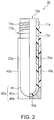
- FIG. 2 is a partial vertical cross-sectional view illustrating the composite preform according to the first embodiment of the present invention.
- FIG. 3 is a partial vertical cross-sectional view illustrating a composite container according to the first embodiment of the present invention.
- FIG. 4 is a horizontal cross-sectional view taken along line IV-IV of the composite container illustrated in FIG. 3 .
- FIG. 5 is a schematic diagram illustrating one embodiment of a method for manufacturing a heat shrinkable plastic member.
- FIG. 6 is a vertical cross-sectional view illustrating a state where a preform is inserted in the heat shrinkable plastic member.
- FIG. 7 is a front view of the heat shrinkable plastic member.
- FIG. 8 is a front view of the preform.
- FIGS. 9( a ) to 9( c ) are diagrams illustrating the shape of a margin bonded by thermocompression.
- FIG. 10 is a schematic diagram illustrating a method for manufacturing the composite container.
- FIG. 11 is a perspective view illustrating the bottom portion side of a composite preform according to a second embodiment of the present invention.
- FIG. 12 is a bottom view illustrating the composite preform according to the second embodiment of the present invention.
- FIG. 13 is a perspective view illustrating a step for performing thermocompression bonding on a margin of the composite preform according to the second embodiment of the present invention.
- FIG. 14 is a front view illustrating the step for performing thermocompression bonding on the margin of the composite preform according to the second embodiment of the present invention.
- FIG. 15 is a partial vertical cross-sectional view of a composite preform according to a third embodiment of the present invention.
- FIG. 16 is a vertical cross-sectional view illustrating a state where a preform is inserted in a heat shrinkable plastic member.
- FIG. 17 is a front view of the heat shrinkable plastic member.
- FIG. 18 is a perspective view illustrating a compression bonding instrument according to the third embodiment of the present invention.
- FIG. 19 is a front view of a composite preform according to a fourth embodiment of the present invention.
- FIG. 20 is a front view illustrating a compression bonding instrument according to the fourth embodiment of the present invention, which has a holding unit and a rotation mechanism and is used for thermocompression-based margin bonding and twist portion formation.
- FIG. 21 is a partial vertical cross-sectional view illustrating a composite preform according to a fifth embodiment of the present invention.
- FIG. 22 is a perspective view illustrating the periphery of the bottom portion of the composite preform according to the fifth embodiment of the present invention.
- FIG. 23 is a perspective view illustrating a pre-thermal shrinkage heat shrinkable plastic member.
- FIGS. 24( a ) to 24( g ) are schematic diagrams illustrating a composite preform production method and a composite container production method according to the fifth embodiment of the present invention.
- FIG. 25 is a perspective view illustrating the periphery of the bottom portion of a composite preform according to a modification example of the fifth embodiment of the present invention.
- FIGS. 1 to 10 are diagrams illustrating the first embodiment of the present invention.
- a composite preform 70 is provided with a preform 10 a formed from a plastic material and a heat shrinkable plastic member 40 a , which has a substantially bottomed cylindrical shape and is provided so as to surround the outside of the preform 10 a.
- the preform 10 a is provided with a mouth portion 11 a , a body portion 20 a connected to the mouth portion 11 a , and a bottom portion 30 a connected to the body portion 20 a.
- the length of the heat shrinkable plastic member 40 a is longer than the lengths of the body portion and the bottom portion of the preform 10 a .
- a margin 80 a for thermocompression bonding is formed in an end portion (one end) 40 b of the plastic member 40 a , which is on the bottom portion 30 a side of the preform 10 a.
- the margin 80 a has a curved surface portion 44 formed along the shape of the bottom portion 30 a of the preform 10 a and a first facing surface 46 a and a second facing surface 46 b respectively protruding from the curved surface portion 44 .
- the first facing surface 46 a and the second facing surface 46 b are bonded and integrated with each other by thermocompression.
- Each of the first facing surface 46 a and the second facing surface 46 b extends substantially in a straight line along the radial direction of the body portion 20 a when viewed from the bottom surface direction. In this case, the first facing surface 46 a and the second facing surface 46 b are compression-bonded over the entire region in the radial direction of the body portion 20 a.
- a composite container 10 A illustrated in FIG. 3 can be obtained by biaxial stretch blow molding being performed on the composite preform 70 and the plastic member 40 a and the preform 10 a of the composite preform 70 being integrally expanded.
- the composite container 10 A is provided with a container main body 10 formed from a plastic material and positioned inside and a plastic member 40 provided in close contact with the outside of the container main body 10 .
- the composite container 10 A is obtained by the heat shrinkable plastic member 40 a and the preform 10 a of the composite preform 70 being integrally expanded by biaxial stretch blow molding being performed on the composite preform 70 by means of a blow molding mold 50 .
- the container main body 10 is provided with a mouth portion 11 , a neck portion 13 provided below the mouth portion 11 , a shoulder portion 12 provided below the neck portion 13 , a body portion 20 provided below the shoulder portion 12 , and a bottom portion 30 provided below the body portion 20 .
- “upper” and “lower” refer to the upper side and the lower side in the upright state of the composite container 10 A ( FIG. 3 ), respectively.
- the mouth portion 11 has a screw portion 14 screwed into a cap (not illustrated) and a flange portion 17 provided below the screw portion 14 .
- the shape of the mouth portion 11 may be a conventionally known shape or the mouth portion 11 may be a stopper-type mouth portion or the like.
- the neck portion 13 is positioned between the flange portion 17 and the shoulder portion 12 and has a substantially cylindrical shape having a substantially uniform diameter.
- the shoulder portion 12 is positioned between the neck portion 13 and the body portion 20 and is shaped so as to have a diameter gradually increasing from the neck portion 13 side toward the body portion 20 side.
- the body portion 20 has a cylindrical shape having a substantially uniform diameter as a whole.
- the present invention is not limited thereto, and the body portion 20 may have a polygonal tubular shape such as a quadrangular tubular shape and an octagonal tubular shape.
- the body portion 20 may have a tubular shape having a horizontal cross section that is not uniform from the top to the bottom.
- the body portion 20 has no unevenness and has a substantially flat surface in the present embodiment, the present invention is not limited thereto.
- the body portion 20 may have an uneven part such as a panel and a groove.
- the bottom portion 30 has a recessed portion 31 positioned in the middle and a ground portion 32 provided around the recessed portion 31 .
- the shape of the bottom portion 30 is not particularly limited, and the bottom portion 30 may have a conventionally known bottom portion shape (such as a petaloid bottom shape and a round bottom shape).
- the thickness of the container main body 10 in the body portion 20 is not limited thereto, the thickness can be reduced to, for example, approximately 50 ⁇ m or more and 250 ⁇ m or less.
- the weight of the container main body 10 is not limited thereto, the weight can be, for example, 10 g or more and 20 g or less in a case where the container main body 10 has an internal capacity of 500 ml. By reducing the wall thickness of the container main body 10 in this manner, it is possible to reduce the weight of the container main body 10 .
- the container main body 10 can be manufactured by biaxial stretch blow molding being performed on the preform 10 a manufactured by injection molding of a resin material.
- a vapor deposited layer such as a diamond-shaped carbon layer and a silicon oxide thin layer may be formed on the inner surface of the container main body 10 so that the barrier properties of the container are enhanced.
- the container main body 10 may be made of, for example, a bottle having a full filling capacity of 100 ml or more and 2,000 ml or less.
- the container main body 10 may be a large bottle having a full filling capacity of, for example, 10 L or more and 60 L or less.
- the heat shrinkable plastic member 40 is attached, without adhesion, to the outer surface of the container main body 10 .
- the heat shrinkable plastic member 40 is brought into close contact with the outer surface of the container main body 10 in a thinly extended state and is attached to the container main body 10 in a state of not moving or rotating with ease.
- the heat shrinkable plastic member 40 is provided over the entire circumferential region of the container main body 10 so as to surround the container main body 10 and has a substantially circular horizontal cross section.
- the plastic member 40 ( 40 a ) is obtained by the plastic member 40 ( 40 a ) being provided so as to surround the outside of the preform 10 a as will be described later, the plastic member 40 ( 40 a ) being brought into close contact with the outside of the preform 10 a , and then biaxial stretch blow molding being performed on the plastic member 40 ( 40 a ) and the preform 10 a .
- the heat shrinkable plastic member 40 is manufactured by the tubular heat shrinkable plastic member 40 a and the preform 10 a being integrally stretched.
- the plastic member 40 can be provided so as to cover the shoulder portion 12 , the body portion 20 , and the bottom portion 30 of the container main body 10 except for the mouth portion 11 and the neck portion 13 .
- the plastic member 40 may be provided so as to cover the neck portion 13 , the shoulder portion 12 , the body portion 20 , and the bottom portion 30 of the container main body 10 except for the mouth portion 11 .
- the thickness of the heat shrinkable plastic member 40 is not limited thereto, the thickness can be, for example, 5 ⁇ m or more and 500 ⁇ m or less, more preferably approximately 5 ⁇ m or more and 50 ⁇ m or less, in a state of being attached to the container main body 10 .
- the heat shrinkable plastic member 40 may be colored in a visible light color such as red, blue, yellow, green, brown, black, and white.
- the heat shrinkable plastic member 40 may be transparent (semitransparent) or opaque.
- the heat shrinkable plastic member 40 may be colored in a visible light color with the container main body 10 colorless and transparent.
- both the container main body 10 and the heat shrinkable plastic member 40 may be colored in a visible light color.
- a pigment having the visible light color may be added to a molding material in a step for manufacturing the heat shrinkable plastic member 40 a before blow molding by extrusion molding or the like.
- the heat shrinkable plastic member 40 is not welded or adhered to the container main body 10 , and thus can be separated (peeled) and removed from the container main body 10 .
- the heat shrinkable plastic member 40 can be separated (peeled) from the container main body 10 by, for example, being cut out by means of a knife or the like or peeled along a cutting line or a notch provided in advance in the heat shrinkable plastic member 40 .
- the heat shrinkable plastic member 40 can be separated and removed from the container main body 10 , and thus it is possible to recycle the container main body 10 that is colorless and transparent as in conventional cases.
- one end of the heat shrinkable plastic member 40 that is on the bottom portion 30 side of the container main body 10 is compression-bonded to form a compression bonding bottom portion 45 A.
- the heat shrinkable plastic member 40 is compression-bonded at a position covering the bottom portion 30 of the container main body 10 .
- the first facing surface 46 a and the second facing surface 46 b ( FIG. 1 ) of the heat shrinkable plastic member 40 a of the composite preform 70 described above are bonded by thermocompression so as to be overlapped with each other.
- an opening 48 d ( FIG. 6 ) of the heat shrinkable plastic member 40 a is blocked after blow molding, and the bottom portion 30 is completely covered by the heat shrinkable plastic member 40 .
- the preform 10 a is prepared. As illustrated in FIGS. 1 and 2 , the preform 10 a is provided with the mouth portion 11 a , the body portion 20 a connected to the mouth portion 11 a , and the bottom portion 30 a connected to the body portion 20 a .
- the mouth portion 11 a corresponds to the mouth portion 11 of the container main body 10 described above and has substantially the same shape as the mouth portion 11 .
- the mouth portion 11 a has a screw portion 14 a screwed into a cap (not illustrated) after the composite container 10 A is manufactured and a flange portion 17 a provided below the screw portion 14 a .
- the body portion 20 a corresponds to the neck portion 13 , the shoulder portion 12 , and the body portion 20 of the container main body 10 described above and has a substantially cylindrical shape.
- the bottom portion 30 a corresponds to the bottom portion 30 of the container main body 10 described above and has a substantially hemispherical shape.
- the preform 10 a can be manufactured by a resin material being injection-molded by means of a conventionally known apparatus.
- a thermoplastic resin is used as the resin material.
- PE polyethylene
- PP polypropylene
- PET polyethylene terephthalate
- PEN polyethylene naphthalate
- PC polycarbonate
- ionomer resin e.g., polyethylene terephthalate
- the preform 10 a may contain a coloring agent such as red, blue, yellow, green, brown, black, and white, it is preferable that the preform 10 a contains no coloring agent and is colorless and transparent in view of the ease of recycling.
- the container main body 10 can be a multilayer molded bottle having two or more layers.
- a multilayer molded bottle having gas barrier properties, light shielding properties, and the like can be obtained once blow molding is performed after molding of the preform 10 a that has the three or more layers including an intermediate layer containing a resin (intermediate layer) having gas barrier properties and light shielding properties such as MXD 6, MXD 6+fatty acid salt, poly glycolic acid (PGA), ethylene vinyl alcohol copolymer (EVOH), and polyethylene naphthalate (PEN).
- a resin obtained by blending of the above-mentioned various resins or the like may be used as the intermediate layer.
- a foamed preform having a foam cell diameter of 0.5 ⁇ m or more and 100 ⁇ m or less may be molded by mixing of an inert gas (nitrogen gas, argon gas) with a molten thermoplastic resin material so that the container main body 10 is manufactured by blow molding of the foamed preform.
- the container main body 10 incorporates a foam cell, and thus the light shielding properties of the entire container main body 10 can be enhanced.
- the heat shrinkable plastic member 40 a is prepared.
- the tubular heat shrinkable plastic member 40 a can be manufactured by a method including an extrusion molding step.
- a resin material or the like to be described later is heated and melted in an extrusion device, the melted resin material or the like is continuously extruded from a ring die and cooled, and then the resin material or the like is molded into an unstretched extrusion tube 1 (see FIG. 5( a ) ).
- the plastic member 40 a that has multiple layers can be manufactured by co-extrusion of two or more resin materials.
- one end of the extrusion tube is closed by welding or adhesion of the one end of the unstretched extrusion tube.
- the extrusion tube 1 is disposed in a mold 2 having an inner diameter larger than the outer diameter of the extrusion tube 1 (see FIG. 5( b ) ).
- a blow device 3 is disposed (mounted) at the other end of the extrusion tube 1 (see FIG. 5( c ) ). At this time, it is preferable that the blow device 3 is brought into close contact with the extrusion tube 1 such that air does not leak from the space between the blow device 3 and the extrusion tube 1 .
- the extrusion tube 1 , the mold 2 , and the blow device 3 are fed into a heating furnace 4 in this disposition and heated to 70 to 150° C. inside the heating furnace 4 (see FIG. 5( d ) ).
- a hot air circulation-type heating furnace may be used as the heating furnace 4 so that the temperature inside the furnace is uniform.
- the extrusion tube 1 , the mold 2 , and the blow device 3 may be heated by being passed through a heated liquid.
- the extrusion tube 1 , the mold 2 , and the blow device 3 are taken out from the heating furnace 4 and air is ejected from the blow device 3 into the extrusion tube 1 .
- the inner surface of the extrusion tube 1 is rolled and stretched. As a result, the extrusion tube 1 expands and is enlarged in diameter along the inner surface shape of the mold 2 (see FIG. 5( e ) ).
- the extrusion tube 1 is cooled in cold water with air ejected from the blow device 3 , and the extrusion tube is taken out from the mold 2 (see FIG. 5( f ) ).
- the tubular heat shrinkable plastic member 40 a is obtained once the tube is cut into a desired size (see FIG. 5( g ) ).
- a commercially available tubular heat shrinkable plastic member 40 a may be used.
- the heat shrinkable plastic member 40 a is capable of containing a resin material such as polyethylene, polypropylene, polyethylene terephthalate, polyethylene naphthalate, poly-4-methylpentene-1, polystyrene, AS resin, ABS resin, polyvinyl chloride, polyvinylidene chloride, polyvinyl acetate, polyvinyl alcohol, polyvinyl acetal, polyvinyl butyral, ionomer resin, diallyl phthalate resin, fluoro-based resin, polymethyl methacrylate, polyacrylic acid, polyacrylic acid methyl, polyacrylonitrile, polyacrylamide, polybutadiene, polybutene-1, polyisoprene, polychloroprene, ethylene propylene rubber, butyl rubber, nitrile rubber, acrylic rubber, silicone rubber, fluoro rubber, nylon 6, nylon 6,6, MXD 6, aromatic polyamide, polycarbonate, butylene polyterephthalate, U polymer, liquid crystal polymer,
- polyethylene, polypropylene, and polystyrene are preferable as the three are capable of further preventing breakage from, for example, a part bonded by thermocompression when blow molding is performed during the production of the composite container 10 A.
- the resin material may contain a copolymer resulting from polymerization of two or more monomer units constituting the above-mentioned resins. Further, the resin material may contain two or more of the above-mentioned resins. Further, various additives may be added to the material of the heat shrinkable plastic member 40 a in addition to the main resin component insofar as the material is not impaired in terms of properties.
- additives examples include a plasticizer, an ultraviolet stabilizer, a coloring inhibitor, a matting agent, a deodorant, a flame retardant, a weathering agent, an antistatic agent, a yarn friction reducing agent, a slip agent, a release agent, an antioxidant, an ion exchanger, and a coloring pigment.
- the heat shrinkable plastic member 40 a may contain a material having gas barrier properties such as oxygen barrier properties and water vapor barrier properties.
- gas barrier properties such as oxygen barrier properties and water vapor barrier properties.
- Conceivable as the material is polyethylene, polypropylene, MXD-6, PGA, EVOH, polyethylene naphthalate, or mixtures of those materials and an oxygen adsorbing material such as fatty acid salt.
- the heat shrinkable plastic member 40 a may be provided with a layer made of the material having gas barrier properties.
- the heat shrinkable plastic member 40 a may contain a material having light ray barrier properties such as ultraviolet ray barrier properties.
- a material having light ray barrier properties such as ultraviolet ray barrier properties.
- Conceivable as the material is a resin material containing two or more of the above-mentioned resins or a material obtained by a light-shielding resin being added to polyethylene terephthalate, polyethylene, or polypropylene.
- a foamed member may be used that has a foam cell diameter of 0.5 to 100 ⁇ m and is manufactured by mixing of an inert gas (nitrogen gas, argon gas) with a molten thermoplastic resin material.
- an inert gas nitrogen gas, argon gas
- the heat shrinkable plastic member 40 a may be provided with a layer made of the material having light ray barrier properties.
- the heat shrinkable plastic member 40 a may contain a material (low-thermal conductivity material) higher in heat retention properties or cold insulation properties than the plastic material constituting the preform 10 a . In this case, it becomes possible to make it difficult for the temperature of a content liquid to be transmitted to the surface of the composite container 10 A without increasing the thickness of the container main body 10 itself. As a result, the heat retention properties or the cold insulation properties of the composite container 10 A are enhanced.
- Conceivable as the material is, for example, foamed polyurethane, polystyrene, polyethylene, polypropylene, phenol resin, polyvinyl chloride, urea resin, silicone, polyimide, and melamine resin.
- the heat shrinkable plastic member 40 a may be provided with a layer made of the material (low-thermal conductivity material) high in heat retention properties or cold insulation properties. Also, it is preferable to mix hollow particles with a resin material containing the resins.
- the average particle diameter of the hollow particles is preferably 1 ⁇ m or more and 200 ⁇ m or less and more preferably 5 ⁇ m or more and 80 ⁇ m or less.
- the “average particle diameter” means a volume average particle diameter and can be measured by a known method and by means of a particle size distribution and particle diameter distribution measuring apparatus (such as the Nanotrac Particle Size Distribution Measuring Apparatus manufactured by Nikkiso Co., Ltd.).
- the hollow particles may be organic hollow particles that are made of resin or the like or may be inorganic hollow particles that are made of glass or the like, the organic hollow particles, which are excellent in dispersibility, are preferable.
- the resin constituting the organic hollow particles include styrene-based resin such as crosslinked styrene-acrylic resin, (meth)acrylic resin such as acrylonitrile-acrylic resin, phenolic resin, fluoro-based resin, polyamide-based resin, polyimide-based resin, polycarbonate-based resin, and polyether-based resin.
- ROPAQUE HP-1055 ROPAQUE HP-91, ROPAQUE OP-84J, ROPAQUE ULTRA, ROPAQUE SE, ROPAQUE ST, (manufactured by Rohm and Haas Co., Ltd.), Nipol MH-5055 (manufactured by Nippon Zeon Co., Ltd.), SX 8782, and SX 866 (manufactured by JSR Corporation).
- the content of the hollow particles is preferably 0.01 parts by mass or more and 50 parts by mass or less and more preferably 1 part by mass or more and 20 parts by mass or less with respect to 100 parts by mass of the resin material contained in the heat shrinkable plastic member 40 a .
- the content of the hollow particles is preferably 0.01 parts by mass or more and 50 parts by mass or less and more preferably 1 part by mass or more and 20 parts by mass or less with respect to 100 parts by mass of the resin material contained in the layer of the heat shrinkable plastic member 40 a that contains the hollow particles.
- the heat shrinkable plastic member 40 a may contain a material less slippery than the plastic material constituting the preform 10 a . In this case, a user can easily grip the composite container 10 A even without changing the material of the container main body 10 .
- the heat shrinkable plastic member 40 a may be provided with a layer made of the material less slippery than the plastic material constituting the preform 10 a . In this case, the layer is preferably the outermost layer of the heat shrinkable plastic member 40 a.
- the heat shrinkable plastic member 40 a may be made of the same material as the container main body 10 (preform 10 a ). In this case, for example, the heat shrinkable plastic member 40 can be disposed mainly at a part of the composite container 10 A where strength enhancement is desired and the strength of the place can be selectively enhanced.
- the material include a thermoplastic resin, especially polyethylene (PE), polypropylene (PP), polyethylene terephthalate (PET), polyethylene naphthalate (PEN), and polycarbonate (PC).
- the length of the heat shrinkable plastic member 40 a is longer than the total length of the body portion 20 a and the bottom portion 30 a of the preform 10 a .
- the heat shrinkable plastic member 40 a has the margin 80 a in the end portion (one end) 40 b .
- the length of the margin 80 a is preferably 3 mm or more and more preferably 5 mm or more and 20 mm or less.
- the length of the heat shrinkable plastic member 40 a is the length of the pre-thermal shrinkage heat shrinkable plastic member 40 a that includes the margin 80 a and is a length X along the axial direction of the heat shrinkable plastic member 40 a .
- the length of the preform 10 a is the length of the body portion 20 a and the bottom portion 30 a of the preform 10 a excluding the mouth portion 11 a and is a length Y measured along the axial direction of the preform 10 a from a region 13 a corresponding to the neck portion 13 to the bottom portion 30 a.
- the heat shrinkable plastic member 40 a may be designed or printed. In this case, it is possible to display an image or a character on the composite container 10 A after blow molding even without separate labeling or the like with respect to the container main body 10 .
- the printing can be performed by a printing method such as an inkjet method, a gravure printing method, an offset printing method, and a flexo printing method.
- a UV curable ink is applied to the heat shrinkable plastic member 40 a ( 40 ), UV irradiation is performed thereon, and curing is performed. Then, it is possible to form a printed layer.
- This printing may be applied to the heat shrinkable plastic member 40 a that is yet to be inserted into the preform 10 a or may be applied in a state where the heat shrinkable plastic member 40 a is provided outside the preform 10 a . Further, printing may be applied to the heat shrinkable plastic member 40 of the composite container 10 A after blow molding.
- the heat shrinkable plastic member 40 a may be colored in a visible light color such as red, blue, yellow, green, brown, black, and white or may be transparent or opaque.
- the heat shrinkable plastic member 40 a manufactured in this manner and open at both ends is inserted into the preform 10 a from one end side. At this time, the heat shrinkable plastic member 40 a covers the periphery of the body portion 20 a and the bottom portion 30 a of the preform 10 a excluding the mouth portion 11 a . In this manner, the preform 10 a is inserted from the side of the heat shrinkable plastic member 40 a that is opposite to the side where the margin 80 a is provided as illustrated in FIG. 6 .
- the preform 10 a and the heat shrinkable plastic member 40 a are heated.
- the heat shrinkable plastic member 40 a undergoes thermal shrinkage and comes into close contact with the outer surface of the preform 10 a.
- Methods for heating the preform 10 a and the heat shrinkable plastic member 40 a are not particularly limited, and the heating can be appropriately performed by means of infrared rays, hot air, or the like.
- the heating temperature is preferably 60° C. or more and 250° C. or less and more preferably 80° C. or more and 150° C. or less.
- the heating temperature is the surface temperature of the heat shrinkable plastic member 40 a during heating and is not the irradiation temperature of infrared rays, hot air, or the like.
- thermocompression bonding can be performed by the end portion 40 b of the plastic member 40 a being sandwiched in a horizontal direction by a pair of compression bonding instruments (not illustrated) after a compression bonding portion is heated by means of infrared rays, hot air, or the like.
- the opening 48 d FIG.
- the material of the compression bonding instrument is not particularly limited, and a metallic instrument or a heat-resistant resin-based instrument can be used. Methods for bonding the margin 80 a by thermocompression are not limited to the above. Insofar as compression bonding can be performed with the margin sandwiched or the like after heating by means of infrared rays, hot air, or the like, a metallic or heat-resistant resin-based instrument (hereinafter, referred to as the “compression bonding instrument” in some cases) or the like can be used and a combination of the instruments may be used.
- the shape of the post-thermocompression bonding margin 80 a is not particularly limited, and the shape can be any shape as illustrated in FIGS. 9( a ) to 9( c ) .
- the first facing surface 46 a and the second facing surface 46 b formed in the end portion 40 b of the plastic member 40 a may be compression-bonded substantially in a straight line along the radial direction of the body portion 20 a when viewed from the bottom surface direction.
- the end portion 40 b of the plastic member 40 a may be compression-bonded in a cross shape when viewed from the bottom surface direction ( FIG. 9( b ) ) and the compression bonding portions of the end portion 40 b may be disposed so as to be equally distributed by approximately 120° when viewed from the bottom surface direction ( FIG. 9( c ) ).
- the surface of the compression bonding instrument may be flat or may have an uneven shape in part or in whole.
- a heating mechanism may be provided on the surface of the compression bonding instrument. Then, it is possible to further enhance the compression bonding strength of the margin 80 a . It is preferable that the heating temperature of the surface of the compression bonding instrument is, for example, 100° C. or more and 250° C. or less.
- the pressure during compression bonding is preferably 50 N/cm 2 or more and 1,000 N/cm 2 or less and more preferably 100 N/cm 2 or more and 500 N/cm 2 or less.
- the temperature of the heat shrinkable plastic member 40 a during compression bonding is preferably 80° C. or more and 200° C. or less although the temperature depends on materials.
- the post-thermocompression bonding margin 80 a may be cut to an appropriate length as desired. Once the margin is cut to the appropriate length (such as approximately 2 mm), the bottom portion has a decent appearance when the composite container is completed.
- the post-thermal shrinkage heat shrinkable plastic member 40 a is not adhered to the outer surface of the preform 10 a and is in close contact with the preform 10 a to the extent of not moving or rotating or to the extent of not falling due to its own weight.
- the plastic member 40 a has a bottomed cylindrical shape and has a cylindrical body portion 41 and a bottom portion 42 connected to the body portion 41 .
- the bottom portion 42 of the plastic member 40 a covers the bottom portion 30 a of the preform 10 a , and thus various functions and characteristics can be imparted to the bottom portion 30 in addition to the body portion 20 of the composite container 10 A.
- the method for manufacturing a composite container according to the present embodiment includes a step for heating the composite preform 70 manufactured as described above and inserting the composite preform 70 into a blow molding mold and a step for integrally expanding the preform 10 a and the heat shrinkable plastic member 40 a by performing blow molding on the composite preform 70 after the heating.
- the composite preform 70 described above is prepared.
- This composite preform 70 is provided with the preform 10 a and the heat shrinkable plastic member 40 a that has a substantially bottomed cylindrical shape and is provided so as to surround the outside of the preform 10 a , and the plastic member 40 a is bonded by thermocompression at the margin 80 a .
- the composite preform 70 is heated by a heating device 51 (see FIG. 10( a ) ).
- the composite preform 70 is uniformly heated in the circumferential direction by the heating device 51 while rotating with the mouth portion 11 a facing downwards.
- the heating temperature of the preform 10 a and the plastic member 40 a in this heating step may be, for example, 90° C. to 130° C.
- the composite preform 70 heated by the heating device 51 is sent to the blow molding mold 50 (see FIG. 10( b ) ).
- the composite container 10 A is molded by means of this blow molding mold 50 .
- the blow molding mold 50 includes a pair of body portion molds 50 a and 50 b divided from each other and a bottom portion mold 50 c (see FIG. 10( b ) ).
- the pair of body portion molds 50 a and 50 b are open to each other, and the bottom portion mold 50 c is raised upwards.
- the composite preform 70 is inserted between the pair of body portion molds 50 a and 50 b.
- the pair of body portion molds 50 a and 50 b are closed after the bottom portion mold 50 c is lowered. Then, the blow molding mold 50 that is sealed by the pair of body portion molds 50 a and 50 b and the bottom portion mold 50 c is constituted. Next, air is pressed into the preform 10 a and biaxial stretch blow molding is applied to the composite preform 70 .
- the container main body 10 is obtained from the preform 10 a in the blow molding mold 50 .
- the body portion molds 50 a and 50 b are heated to 30° C. to 80° C. and the bottom portion mold 50 c is cooled to 5° C. to 25° C.
- the plastic member 40 a and the preform 10 a of the composite preform 70 are integrally expanded in the blow molding mold 50 .
- the preform 10 a and the plastic member 40 a are integrated into a shape corresponding to the inner surface of the blow molding mold 50 .
- the pair of body portion molds 50 a and 50 b and the bottom portion mold 50 c are separated from each other and the composite container 10 A is taken out from the inside of the blow molding mold 50 .
- the preform 10 a that is made of PET and illustrated in FIG. 8 was manufactured by means of an injection molding machine.
- the weight of this preform 10 a was 23.8 g and the length Y of the preform 10 a was 90 mm.
- a polyolefin resin was melted and extruded from a ring-shaped die. Next, diameter enlargement was performed by the inner surface of the extruded tube being pressurized or the outer surface of the tube being given a negative pressure from the inner surface, and the heat shrinkable plastic member 40 a was manufactured.
- the length X of the manufactured heat shrinkable plastic member 40 a was 100 mm and the length of the margin 80 a was 10 mm.
- the preform 10 a was manually inserted from the end of the heat shrinkable plastic member 40 a that is opposite to the margin 80 a.
- thermal shrinkage was performed on the heat shrinkable plastic member 40 a by the preform 10 a and the heat shrinkable plastic member 40 a being heated to 100° C. by means of an infrared heater.
- the margin 80 a was sandwiched and bonded by thermocompression at a pressure of 300 N/cm 2 by means of a metal plate heated to 100° C., and the composite preform 70 was obtained.
- the composite preform 70 obtained as described above was heated to 100° C. by means of an infrared heater and transported to the blow molding mold that is illustrated in FIG. 10 b .
- the composite preform 70 was blow-molded in this blow molding mold, and the composite container 10 A having a full filling capacity of 500 mL was obtained.
- the plastic member 40 of the composite container 10 A covered the bottom portion 30 of the container main body 10 , and no compression bonding portion peeling or breakage was observed.
- FIGS. 11 to 14 are diagrams illustrating the second embodiment of the present invention.
- the position where the margin 80 a is compression-bonded is different, and the other configurations are substantially identical to those of the first embodiment described above.
- the same parts as those of the first embodiment illustrated in FIGS. 1 to 13 are denoted by the same reference numerals, and detailed description thereof will be omitted.
- the first facing surface 46 a and the second facing surface 46 b that are disposed to face each other are formed at the margin 80 a .
- the first facing surface 46 a and the second facing surface 46 b are formed in an annular shape as a whole and constitute the end portion 40 b of the plastic member 40 a.
- a part of the first facing surface 46 a and a part of the second facing surface 46 b are compression-bonded to each other.
- a first compression bonding part 46 c having a substantially intermediate position in the radial direction of the body portion 20 a in the first facing surface 46 a and a second compression bonding part 46 d having a substantially intermediate position in the radial direction of the body portion 20 a in the second facing surface 46 b are bonded by thermocompression to each other.
- the first compression bonding part 46 c and the second compression bonding part 46 d are connected to each other, and the first facing surface 46 a and the second facing surface 46 b are integrated.
- the first facing surface 46 a and the second facing surface 46 b are formed in the shape of ⁇ (or number 8) as a whole when viewed from the bottom surface direction. Accordingly, a pair of openings 48 e and 48 f are formed between the first facing surface 46 a and the second facing surface 46 b.
- the first facing surface 46 a and the second facing surface 46 b are compression-bonded in a state of mutual misalignment in the upward-downward direction (axial direction of the heat shrinkable plastic member 40 a ).
- an end edge 46 e of the first facing surface 46 a and an end edge 46 f of the second facing surface 46 b are mutually misaligned in a state where the first compression bonding part 46 c and the second compression bonding part 46 d are compression-bonded.
- the end edge 46 f of the second facing surface 46 b is positioned more outwards than the end edge 46 e of the first facing surface 46 a (on a side that is far from the body portion 20 a ).
- a step for compression-bonding a part of the first facing surface 46 a and a part of the second facing surface 46 b to each other follows a step for performing thermal shrinkage on the heat shrinkable plastic member 40 a and precedes a step for heating the composite preform 70 by means of the heating device 51 ( FIG. 10( a ) ).
- first compression bonding part 46 c of the first facing surface 46 a and the second compression bonding part 46 d of the second facing surface 46 b are sandwiched inwards, by means of a thermocompression bonding tool or the like, in a state where the heat shrinkable plastic member 40 a has a high temperature immediately after the thermal shrinkage step, and the first compression bonding part 46 c and the second compression bonding part 46 d are compression-bonded as a result.
- each of the pair of compression bonding instruments 90 D and 90 E has a compression bonding point 90 F.
- the compression bonding instrument 90 D is thicker than the compression bonding instrument 90 E.
- a pair of compression bonding instruments 90 A and 90 B are brought close to each other from both sides in the axial direction of the plastic member 40 a such that the pair of compression bonding points 90 F sandwich the first facing surface 46 a and the second facing surface 46 b .
- thermocompression shape of the part where the first facing surface 46 a and the second facing surface 46 b are bonded by thermocompression (shapes of the first compression bonding part 46 c and the second compression bonding part 46 d viewed from the front side) can be circular, square, rectangular, rhombic, and so on.
- first facing surface 46 a and the second facing surface 46 b may be melted and compression-bonded by means of a heated tool (not illustrated) or the like after cooling of the heat shrinkable plastic member 40 a .
- first facing surface 46 a and the second facing surface 46 b may be melted and compression-bonded by means of heat generation resulting from ultrasonic vibration of a tool (not illustrated) or the like after cooling of the heat shrinkable plastic member 40 a.
- the margin 80 a is deformed such that the first facing surface 46 a and the second facing surface 46 b are narrowed during blow molding of the composite preform 70 , and thus the heat shrinkable plastic member 40 and the bottom portion 30 of the container main body 10 are in close contact with uniformity after the blow molding and the appearance of the bottom portion 30 can be decent.
- air is discharged from the pair of openings 48 e and 48 f in the blow molding step, and thus it is possible to more effectively restrain air from remaining between the heat shrinkable plastic member 40 and the bottom portion 30 of the container main body 10 .
- a part of the first facing surface 46 a and a part of the second facing surface 46 b are compression-bonded to each other, and thus the close contact between the heat shrinkable plastic member 40 and the bottom portion 30 of the container main body 10 can be made more reliable, and it is possible to manufacture the composite container 10 A that is decent in appearance and excellent in light shielding properties with high quality.
- the end edge 46 e of the first facing surface 46 a and the end edge 46 f of the second facing surface 46 b are mutually misaligned in a state where the first compression bonding part 46 c and the second compression bonding part 46 d are compression-bonded.
- the pair of openings 48 e and 48 f are unlikely to be closed during blow molding of the composite preform 70 , and thus air is easily discharged from the pair of openings 48 e and 48 f and air stagnation between the heat shrinkable plastic member 40 and the bottom portion 30 of the container main body 10 can be further suppressed.
- FIGS. 15 to 18 are diagrams illustrating the third embodiment of the present invention.
- the third embodiment illustrated in FIGS. 15 to 18 differs from the first embodiment in that the plastic member 40 a has an end portion compression-bonded along the shape of the bottom portion 30 a of the preform 10 a to form a compression bonding bottom portion 45 , and the other configurations are substantially identical to those of the first embodiment described above.
- the same parts as those of the first embodiment illustrated in FIGS. 1 to 10 are denoted by the same reference numerals, and detailed description thereof will be omitted.
- FIG. 15 is a diagram illustrating the composite preform 70 according to the present embodiment.
- the composite preform 70 according to the present embodiment is provided with the preform 10 a formed from a plastic material and the heat shrinkable plastic member 40 a , which has a substantially bottomed cylindrical shape and is provided so as to surround the outside of the preform 10 a.
- the end portion 40 b of the plastic member 40 a on the bottom portion side of the preform 10 a is compression-bonded along the shape of the bottom portion 30 a of the preform 10 a to form the compression bonding bottom portion 45 .
- the composite container 10 A can be obtained by blow molding of the composite preform 70 illustrated in FIG. 15 .
- the configuration of the preform 10 a is identical to that illustrated in the first embodiment (see FIGS. 1 and 2 ), and detailed description thereof will be omitted here.
- the heat shrinkable plastic member 40 a is provided so as to surround the outside of the preform 10 a , without adhering to the preform 10 a , and is in close contact with the preform 10 a to the extent of not moving or rotating or to the extent of not falling due to its own weight.
- the heat shrinkable plastic member 40 a is provided over the entire circumferential region of the preform 10 a so as to surround the preform 10 a . As illustrated in FIG. 15 , one end of the heat shrinkable plastic member 40 a that is on the bottom portion 30 a side of the preform 10 a is bonded by thermocompression along the shape of the bottom portion 30 a of the preform 10 a to form the compression bonding bottom portion 45 .
- the compression bonding bottom portion 45 of the heat shrinkable plastic member 40 a has a curved surface portion 43 formed along the shape of the bottom portion 30 a of the preform 10 a and a first piece 47 a and a second piece 47 b respectively protruding from the curved surface portion 43 .
- the first piece 47 a and the second piece 47 b are bonded and integrated with each other by thermocompression.
- Each of the first piece 47 a and the second piece 47 b extends substantially in a straight line along the radial direction of the body portion 20 a when viewed from the bottom surface direction.
- the first piece 47 a and the second piece 47 b are compression-bonded over the entire region in the radial direction of the body portion 20 a.
- the heat shrinkable plastic member 40 a By one end of the heat shrinkable plastic member 40 a being bonded by thermocompression along the shape of the bottom portion 30 a of the preform 10 a as described above, it is possible to obtain the composite container 10 A in which the bottom portion 30 of the container main body 10 is covered with the plastic member 40 and it is possible to improve the close contactability of the plastic member 40 with respect to the container main body 10 as bubbles are not generated during blow molding. In addition, since no bubbles are present, the appearance of the composite container 10 A can be improved as well.
- the same material as that illustrated in the first embodiment can be used as the material of the heat shrinkable plastic member 40 a.
- the method for manufacturing the composite preform 70 includes a step for preparing the preform 10 a provided with the mouth portion 11 a , the body portion 20 a connected to the mouth portion 11 a , and the bottom portion 30 a connected to the body portion 20 a , a step for preparing the tubular heat shrinkable plastic member 40 a longer than the preform 10 a , a step for inserting the preform 10 a from one end of the plastic member 40 a , a step for performing thermal shrinkage on the plastic member 40 a by heating the preform 10 a and the plastic member 40 a , and a step for bonding the other end of the plastic member 40 a on the bottom portion 30 a side of the preform 10 a by thermocompression along the shape of the bottom portion 30 a of the preform 10 a.
- the preform 10 a and the heat shrinkable plastic member 40 a are prepared as in the case of the first embodiment.
- the length of the heat shrinkable plastic member 40 a is longer than the sum of the lengths of the body portion 20 a and the bottom portion 30 a of the preform 10 a .
- the length of the heat shrinkable plastic member 40 a exceeds the length of the body portion 20 a and the bottom portion 30 a of the preform 10 a preferably by 3 mm or more and more preferably by 5 mm or more and 20 mm or less.
- the length of the heat shrinkable plastic member 40 a is the length of the pre-thermal shrinkage heat shrinkable plastic member 40 a and is the length X along the axial direction of the heat shrinkable plastic member 40 a .
- the sum of the lengths of the body portion 20 a and the bottom portion 30 a of the preform 10 a is the length of the body portion 20 a and the bottom portion 30 a of the preform 10 a excluding the mouth portion 11 a and is the length Y along the axial direction of the preform 10 a (see FIG. 8 ).
- the heat shrinkable plastic member 40 a manufactured in this manner and open at both ends is inserted into the preform 10 a from one end side.
- the preform 10 a is inserted from one end of the heat shrinkable plastic member 40 a as illustrated in FIG. 16 .
- the preform 10 a and the heat shrinkable plastic member 40 a are heated.
- the heat shrinkable plastic member 40 a undergoes thermal shrinkage and comes into close contact with the outer surface of the preform 10 a.
- thermocompression bonding can be performed by the end portion 40 b of the plastic member 40 a being sandwiched by the pair of compression bonding instruments 90 A and 90 B illustrated in FIG. 18 after a compression bonding portion is heated by means of infrared rays, hot air, or the like.
- Each of the pair of compression bonding instruments 90 A and 90 B has a substantially semicylindrical (or substantially hemispherical) recessed receiving portion 90 C having a shape corresponding to the bottom portion 30 a of the preform 10 a .
- the pair of compression bonding instruments 90 A and 90 B are brought close to each other from both sides in the axial direction of the plastic member 40 a and moved such that the pair of recessed receiving portions 90 C wrap the bottom portion 30 a of the preform 10 a .
- the opening 48 d formed in the cylindrical end portion 40 b of the plastic member 40 a is blocked, and the first piece 47 a and the second piece 47 b can be bonded by thermocompression and form the compression bonding bottom portion 45 .
- the materials of the compression bonding instruments 90 A and 90 B are not particularly limited, and a metallic instrument or a heat-resistant resin-based instrument can be used.
- the end portion 40 b of the plastic member 40 a can be bonded by thermocompression along the bottom portion 30 a of the preform 10 a by means of the compression bonding instruments 90 A and 90 B illustrated in FIG. 18 .
- the shapes of the compression bonding instruments 90 A and 90 B are not particularly limited insofar as the plastic member 40 a can be bonded by thermocompression along the bottom portion 30 a of the preform 10 a .
- the surface of the recessed receiving portion 90 C of the compression bonding instruments 90 A and 90 B may be flat or may have an uneven shape in part or in whole.
- a heating mechanism may be provided on the surfaces of the compression bonding instruments 90 A and 90 B. Then, it is possible to further enhance the compression bonding strength. It is preferable that the heating temperature of the surface of the compression bonding instrument is, for example, 100° C. or more and 250° C. or less.
- the pressure during compression bonding is preferably 50 N/cm 2 or more and 1,000 N/cm 2 or less and more preferably 100 N/cm 2 or more and 500 N/cm 2 or less.
- the temperature of the heat shrinkable plastic member 40 a during compression bonding is preferably 80° C. or more and 200° C. or less although the temperature depends on materials.
- the end portion 40 b of the plastic member 40 a may be cut to an appropriate length as desired.
- the bottom portion 30 has a decent appearance when the composite container 10 A is completed.
- the cutting is performed such that a length Z (see FIG. 1 ) from the vertex of the bottom portion 30 a of the preform 10 a to the endmost part of the compression-bonded plastic member 40 a is 0.5 mm or more and 5 mm or less.
- the compression bonding bottom portion 45 may be linearly cut or may be cut in a curved shape (not illustrated) along the shape of the bottom portion of the preform 10 a.
- the post-thermal shrinkage heat shrinkable plastic member 40 a is not adhered to the outer surface of the preform 10 a and is in close contact with the preform 10 a to the extent of not moving or rotating or to the extent of not falling due to its own weight.
- the configuration of the composite container 10 A manufactured by means of the composite preform 70 according to the present embodiment is substantially identical to that according to the first embodiment.
- the heat shrinkable plastic member 40 is in close contact with the outer surface of the container main body 10 in a thinly extended state and is attached to the container main body 10 in a state of not moving or rotating with ease.
- One end of the heat shrinkable plastic member 40 on the bottom portion 30 side of the container main body 10 is compression-bonded to form the compression bonding bottom portion 45 A (see FIG. 3 ).
- the heat shrinkable plastic member 40 is compression-bonded at a position covering the bottom portion 30 of the container main body 10 .
- the first piece 47 a and the second piece 47 b ( FIG. 15 ) of the heat shrinkable plastic member 40 a of the composite preform 70 described above are bonded by thermocompression so as to be overlapped with each other.
- the opening 48 d ( FIG. 18 ) of the heat shrinkable plastic member 40 a is blocked after blow molding, and the bottom portion 30 is completely covered by the heat shrinkable plastic member 40 .
- the method for manufacturing the composite container 10 A according to the present embodiment is substantially identical to that according to the first embodiment.
- the method for manufacturing the composite container 10 A according to the present embodiment includes a step for heating the composite preform 70 described above and inserting the composite preform 70 into a blow molding mold and a step for integrally expanding the preform 10 a and the heat shrinkable plastic member 40 a by performing blow molding on the composite preform 70 after the heating.
- the preform 10 a that is made of PET and illustrated in FIG. 8 was manufactured by means of an injection molding machine.
- the weight of this preform 10 a was 23.8 g and the sum Y of the lengths of the body portion 20 a and the bottom portion 30 a of the preform 10 a was 90 mm.
- a polyolefin resin was melted and extruded from a ring-shaped die. Next, diameter enlargement was performed by the inner surface of the extruded tube being pressurized or the outer surface of the tube being given a negative pressure from the inner surface, and the heat shrinkable plastic member 40 a was manufactured.
- the length X of the manufactured heat shrinkable plastic member 40 a was 100 mm.
- the preform 10 a was manually inserted from one end of the heat shrinkable plastic member 40 a.
- thermocompression bonding was performed along the shape of the bottom portion 30 a of the preform 10 a by one end of the plastic member 40 a being sandwiched at a pressure of 300 N/cm 2 by means of the pair of compression bonding instruments 90 A and 90 B heated to 100° C. and illustrated in FIG. 18 , and the composite preform 70 was obtained.
- the composite preform 70 obtained as described above was heated to 100° C. by means of an infrared heater and transported to a blow molding mold.
- the composite preform 70 was blow-molded in this blow molding mold, and the composite container 10 A having a full filling capacity of 500 mL was obtained.
- the plastic member 40 of the composite container 10 A covered the bottom portion of the container main body 10 . In addition, no compression bonding portion peeling or breakage was observed and no presence of bubbles could be confirmed.
- FIGS. 19 to 20 are diagrams illustrating the fourth embodiment of the present invention.
- the fourth embodiment illustrated in FIGS. 19 to 20 differs from the first embodiment in that the plastic member 40 a has an end portion where a twist portion 80 is formed, and the other configurations are substantially identical to those of the first embodiment described above.
- the same parts as those of the first embodiment illustrated in FIGS. 1 to 10 are denoted by the same reference numerals, and detailed description thereof will be omitted.
- FIG. 19 is a diagram illustrating the composite preform 70 according to the present embodiment. As illustrated in FIG. 19 , the composite preform 70 according to the present embodiment is provided with the preform 10 a formed from a plastic material and the heat shrinkable plastic member 40 a , which has a substantially bottomed cylindrical shape and is provided so as to surround the outside of the preform 10 a.
- the preform 10 a is provided with the mouth portion 11 a , the body portion 20 a connected to the mouth portion 11 a , and the bottom portion 30 a connected to the body portion 20 a .
- the configuration of the preform 10 a is identical to that illustrated in the first embodiment, and detailed description thereof will be omitted here.
- the length of the heat shrinkable plastic member 40 a is longer than the lengths of the body portion 20 a and the bottom portion 30 a of the preform 10 a .
- the margin 80 a for thermocompression bonding is formed in the end portion (one end) 40 b of the plastic member 40 a , which is on the bottom portion 30 a side of the preform 10 a .
- This margin 80 a is bonded by thermocompression and twisted, and the twist portion 80 is formed as a result.
- the composite container 10 A can be obtained by blow molding of the composite preform 70 illustrated in FIG. 19 .
- the configuration of the composite container 10 A manufactured by means of the composite preform 70 according to the present embodiment is substantially identical to that according to the first embodiment.
- the heat shrinkable plastic member 40 is in close contact with the outer surface of the container main body 10 in a thinly extended state and is attached to the container main body 10 in a state of not moving or rotating with ease.
- One end of the heat shrinkable plastic member 40 on the bottom portion 30 side of the container main body 10 is compression-bonded to form the compression bonding bottom portion 45 A (see FIG. 3 ).
- the heat shrinkable plastic member 40 is compression-bonded at a position covering the bottom portion 30 of the container main body 10 .
- thermocompression bonding is performed such that the twist portion 80 (see FIG. 19 ) of the above-described composite preform 70 is crushed.
- the opening 48 d (see FIG. 6 ) of the heat shrinkable plastic member 40 a is blocked after blow molding, and the bottom portion 30 is completely covered by the heat shrinkable plastic member 40 .
- the method for manufacturing the composite preform 70 includes a step for preparing the preform 10 a provided with the mouth portion 11 a , the body portion 20 a connected to the mouth portion 11 a , and the bottom portion 30 a connected to the body portion 20 a , a step for preparing the tubular heat shrinkable plastic member 40 a having the margin 80 a for thermocompression bonding at one end, a step for inserting the preform 10 a from the other end of the plastic member 40 a , a step for performing thermal shrinkage on the plastic member 40 a by heating the plastic member 40 a , a step for bonding the margin 80 a of the plastic member 40 a by thermocompression, and a step for forming the twist portion 80 by twisting the margin 80 a bonded by thermocompression.
- the preform 10 a and the heat shrinkable plastic member 40 a are prepared as in the case of the first embodiment.
- the length of the heat shrinkable plastic member 40 a is longer than the total length of the body portion 20 a and the bottom portion 30 a of the preform 10 a .
- the heat shrinkable plastic member 40 a has the margin 80 a in the end portion (one end) 40 b (see FIG. 6 ).
- the length of the margin 80 a is preferably 3 mm or more and more preferably 5 mm or more and 20 mm or less.
- the heat shrinkable plastic member 40 a open at both ends is inserted into the preform 10 a from one end side.
- the heat shrinkable plastic member 40 a covers the periphery of the body portion 20 a and the bottom portion 30 a of the preform 10 a excluding the mouth portion 11 a .
- the preform 10 a is inserted from the side of the heat shrinkable plastic member 40 a that is opposite to the side where the margin 80 a is provided.
- the preform 10 a and the heat shrinkable plastic member 40 a are heated.
- the heat shrinkable plastic member 40 a undergoes thermal shrinkage and comes into close contact with the outer surface of the preform 10 a .
- the post-thermal shrinkage heat shrinkable plastic member 40 a is not adhered to the outer surface of the preform 10 a and is in close contact with the preform 10 a to the extent of not moving or rotating or to the extent of not falling due to its own weight.
- thermocompression bonding the margin 80 a by thermocompression are not particularly limited, and the thermocompression bonding can be performed by, for example, a method similar to that according to the first embodiment.
- the margin 80 a bonded by thermocompression is twisted, and then the twist portion 80 illustrated in FIG. 19 is formed.
- the plastic member 40 a in which the twist portion 80 is formed by twisting of the margin 80 a it is possible to obtain the plastic member 40 that is provided with a bottom portion which is decent in appearance.
- twist portion 80 can be formed by the margin 80 a being manually twisted by means of an instrument such as pliers.
- the formation can be mechanically performed by means of, for example, a rotary device (see FIG. 20 ) including a holding unit 81 holding the preform 10 a and the plastic member 40 a and compression bonding instruments 82 and 83 having a rotation mechanism.
- the formation may be performed based on a combination of those methods.
- the twist portion 80 can be formed by the margin 80 a being sandwiched by means of an instrument such as pliers and the preform 10 a and the plastic member 40 a being rotated by a rotation unit.
- the formation of the twist portion 80 can be performed simultaneously with thermocompression bonding of the margin 80 a . Then, it is possible to reduce the number of work steps and further improve productivity. Specifically, it is possible to form the twist portion 80 by providing the rotation mechanism in the compression bonding instruments 82 and 83 , fixing the preform 10 a and the plastic member 40 a to the holding unit 81 , and rotating the compression bonding instruments 82 and 83 . Also, it is possible to form the twist portion 80 by using the compression bonding instruments 82 and 83 as holding units and rotating the preform 10 a and the plastic member 40 a by means of the rotation unit. The extent to which the margin 80 a is twisted is not particularly limited.
- the extent may be approximately 0.25 rotations or more and 30 rotations or less or the twisting may be performed until the margin 80 a is twisted off, it is preferable that the twisting is performed until the margin 80 a is twisted off so that the appearance can be improved and breakage of the thermocompression-bonded part attributable to blow molding can be prevented more effectively.
- the method for manufacturing the composite container 10 A according to the present embodiment is substantially identical to that according to the first embodiment.
- the method for manufacturing the composite container 10 A according to the present embodiment includes a step for heating the composite preform 70 manufactured as described above and inserting the composite preform 70 into a blow molding mold and a step for integrally expanding the preform 10 a and the heat shrinkable plastic member 40 a by performing blow molding on the composite preform 70 after the heating.
- the preform 10 a that is made of PET and illustrated in FIG. 8 was manufactured by means of an injection molding machine.
- the weight of this preform 10 a was 23.8 g and the length Y of the body portion 20 a and the bottom portion 30 a of the preform 10 a was 90 mm.
- a polyolefin resin was melted and extruded from a ring-shaped die. Next, diameter enlargement was performed by the inner surface of the extruded tube being pressurized or the outer surface of the tube being given a negative pressure from the inner surface, and the heat shrinkable plastic member 40 a was manufactured.
- the length X of the manufactured heat shrinkable plastic member 40 a was 100 mm and the length of the margin 80 a was 10 mm.
- the preform 10 a was manually inserted from the end of the heat shrinkable plastic member 40 a that is opposite to the margin 80 a.
- thermal shrinkage was performed on the heat shrinkable plastic member 40 a by the preform 10 a and the heat shrinkable plastic member 40 a being heated to 100° C. by means of an infrared heater.
- the preform 10 a and the plastic member 40 a were fixed to the holding unit 81 illustrated in FIG. 20 , and thermocompression bonding was performed by the margin 80 a being sandwiched at a pressure of 300 N/cm 2 by means of the rotation mechanism-equipped compression bonding instruments 82 and 83 illustrated in FIG. 20 and heated to 100° C. Further, the preform 10 a and the plastic member 40 a were rotated by the rotation mechanism until the compression-bonded margin 80 a was twisted off and the twist portion 80 (see FIG. 19 ) was formed.
- the composite preform 70 obtained as described above was heated to 100° C. by means of an infrared heater and transported to a blow molding mold.
- the composite preform 70 was blow-molded in this blow molding mold, and the composite container 10 A having a full filling capacity of 500 mL was obtained.
- the container main body 10 was covered up to the bottom portion of the container main body 10 by the plastic member 40 . No bubbles were observed between the container main body 10 and the plastic member 40 .
- FIGS. 21 to 25 are diagrams illustrating the fifth embodiment of the present invention.
- the fifth embodiment illustrated in FIGS. 21 to 25 mainly differs from the first embodiment in that a first notch portion 49 a and a second notch portion 49 b are formed in the plastic member 40 a , and the other configurations are substantially identical to those of the first embodiment described above.
- FIGS. 21 to 25 the same parts as those of the first embodiment illustrated in FIGS. 1 to 10 are denoted by the same reference numerals, and detailed description thereof will be omitted.
- the configuration of the composite container 10 A according to the present embodiment is substantially identical to that according to the first embodiment ( FIGS. 3 and 4 ).
- the heat shrinkable plastic member 40 is compression-bonded at a position covering the bottom portion 30 of the container main body 10 to form the compression bonding bottom portion 45 A.
- thermocompression bonding is performed such that the first piece 47 a and the second piece 47 b ( FIG. 22 ) of the heat shrinkable plastic member 40 a of the composite preform 70 , which will be described later, are overlapped with each other.
- the opening 48 d ( FIGS. 21 and 22 ) of the heat shrinkable plastic member 40 a is blocked after blow molding, and the bottom portion 30 is completely covered by the heat shrinkable plastic member 40 .
- the composite preform 70 is provided with the preform 10 a formed from a plastic material and the heat shrinkable plastic member 40 a , which has a substantially cylindrical shape and is provided so as to surround the outside of the preform 10 a.
- the preform 10 a is provided with the mouth portion 11 a , the body portion 20 a connected to the mouth portion 11 a , and the bottom portion 30 a connected to the body portion 20 a .
- the configuration of the preform 10 a is identical to that illustrated in the first embodiment, and detailed description thereof will be omitted here.
- the heat shrinkable plastic member 40 a is attached, without adhesion, to the outer surface of the preform 10 a .
- the heat shrinkable plastic member 40 a is in close contact with the preform 10 a to the extent of not moving or rotating or to the extent of not falling due to its own weight.
- the heat shrinkable plastic member 40 a is provided over the entire circumferential region of the preform 10 a so as to surround the preform 10 a and has a circular horizontal cross section.
- the heat shrinkable plastic member 40 a is provided so as to cover the mouth portion 11 a and the entire region of the bottom portion 30 a excluding a lower surface 30 b.
- the heat shrinkable plastic member 40 a has a large diameter portion 48 a and a diameter reduced portion 48 b smaller in diameter than the large diameter portion 48 a .
- a transition portion 48 c is interposed between the large diameter portion 48 a and the diameter reduced portion 48 b.
- the large diameter portion 48 a is substantially cylindrical and covers the entire region of the body portion 20 a of the preform 10 a .
- the present invention is not limited thereto, and the large diameter portion 48 a may cover a part of the body portion 20 a such as a region other than the region 13 a corresponding to the neck portion 13 .
- the diameter reduced portion 48 b is substantially cylindrical as a whole and extends from the bottom portion 30 a of the preform 10 a toward the outside (side opposite to the mouth portion 11 a ).
- the opening 48 d is formed in the region that is surrounded by the diameter reduced portion 48 b .
- the lower surface 30 b of the bottom portion 30 a is exposed outwards from the opening 48 d .
- the diameter reduced portion 48 b is contraction-formed so as to be smaller in diameter than the large diameter portion 48 a by thermal shrinkage of the heat shrinkable plastic member 40 a .
- a length L 1 of the diameter reduced portion 48 b may be, for example, 30% or more and 100% or less of a diameter D 1 of the large diameter portion 48 a .
- a diameter D 2 of the diameter reduced portion 48 b may be, for example, 30% or more and 90% or less of the diameter D 1 of the large diameter portion 48 a.
- the transition portion 48 c is connected to the large diameter portion 48 a and the diameter reduced portion 48 b .
- This transition portion 48 c is formed along the bottom portion 30 a of the preform 10 a .
- the transition portion 48 c corresponds to the shape of the bottom portion 30 a , and constitutes a part of a spherical surface in this case.
- the horizontal cross section of the transition portion 48 c is substantially circular with a diameter gradually decreasing from the large diameter portion 48 a toward the diameter reduced portion 48 b.
- FIG. 22 is a perspective view illustrating the part of the heat shrinkable plastic member 40 a that is around the bottom portion 30 a .
- each of the first notch portion 49 a and the second notch portion 49 b is formed in the diameter reduced portion 48 b .
- the first notch portion 49 a and the second notch portion 49 b are provided at positions facing each other in the radial direction of the diameter reduced portion 48 b .
- Each of the first notch portion 49 a and the second notch portion 49 b is formed in a linear or V shape in the longitudinal direction of the preform 10 a along the wall surface of the diameter reduced portion 48 b .
- a length (length along the longitudinal direction of the preform 10 a ) L 2 of the first notch portion 49 a and the second notch portion 49 b is, for example, 3 mm or more and 20 mm or less.
- the length L 2 is a length that does not reach the bottom portion 30 a of the preform 10 a.
- the diameter reduced portion 48 b is provided with the first piece 47 a and the second piece 47 b separated from each other by the first notch portion 49 a and the second notch portion 49 b .
- Each of the first piece 47 a and the second piece 47 b has a substantially semicircular arc shape when viewed from the bottom surface direction.
- the first piece 47 a and the second piece 47 b face each other across the opening 48 d.
- the first notch portion 49 a and the second notch portion 49 b being formed at positions facing each other in the diameter reduced portion 48 b as described above, the first piece 47 a and the second piece 47 b collapse in a direction in which the first piece 47 a and the second piece 47 b approach each other when the composite preform 70 is blow-molded.
- no gap is formed between the heat shrinkable plastic member 40 a and the bottom portion 30 a of the preform 10 a , and thus the heat shrinkable plastic member 40 and the bottom portion 30 of the container main body 10 are substantially uniformly covered after blow molding. Accordingly, the appearance, the light shielding properties, and the gas barrier properties of the heat shrinkable plastic member 40 in the bottom portion 30 are not deteriorated.
- FIG. 23 is a perspective view illustrating the heat shrinkable plastic member 40 a before thermal shrinkage (before mounting on the preform 10 a ).
- the heat shrinkable plastic member 40 a is substantially cylindrical as a whole and has the body portion 41 and one end 41 a and the other end 41 b , which are respectively formed at both longitudinal ends of the body portion 41 .
- the one end 41 a of the body portion 41 is an end portion facing the mouth portion 11 a side when the heat shrinkable plastic member 40 a is mounted on the preform 10 a
- the other end 41 b of the body portion 41 is an end portion facing the bottom portion 30 a.
- first notch portion 49 a and the second notch portion 49 b are respectively formed at positions facing each other at the one end 41 a of the heat shrinkable plastic member 40 a .
- Each of the first notch portion 49 a and the second notch portion 49 b is linearly formed in the longitudinal direction of the body portion 41 , and each of the first notch portion 49 a and the second notch portion 49 b terminates midway in the longitudinal direction of the body portion 41 from the one end 41 a of the body portion 41 .
- first piece 47 a and the second piece 47 b (before thermal shrinkage) separated from each other by the first notch portion 49 a and the second notch portion 49 b are formed at the one end 41 a of the heat shrinkable plastic member 40 a .
- a length L 3 of the first notch portion 49 a and the second notch portion 49 b before thermal shrinkage is, for example, 5 mm or more and 20 mm or less.
- One that has a thermal shrinkage action with respect to the preform 10 a is used as the heat shrinkable plastic member 40 a .
- the heat shrinkable plastic member 40 a one that contracts with respect to the preform 10 a when heat is applied or the like is used as the heat shrinkable plastic member (outside contraction member) 40 a.
- the preform 10 a formed from a plastic material is prepared (see FIG. 24( a ) ).
- the preform 10 a is manufactured by an injection molding method and by means of, for example, an injection molding machine (not illustrated).
- the preform 10 a has the mouth portion 11 a , the cylindrical body portion 20 a , and the substantially hemispherical bottom portion 30 a.
- the substantially cylindrical heat shrinkable plastic member 40 a that has the one end 41 a and the other end 41 b is prepared ( FIG. 23 ).
- the first notch portion 49 a and the second notch portion 49 b are respectively formed at positions facing each other at the one end 41 a of this heat shrinkable plastic member 40 a.
- the heat shrinkable plastic member (outside contraction member) 40 a is provided (loosely inserted) outside the preform 10 a (see FIG. 24( b ) ).
- the heat shrinkable plastic member 40 a is loosely inserted into the preform 10 a from the other end 41 b side.
- the heat shrinkable plastic member 40 a is mounted so as to cover the entire region of the body portion 20 a of the preform 10 a and the entire region of the bottom portion 30 a as viewed from the side.
- the one end 41 a of the heat shrinkable plastic member 40 a protrudes to the outside (side opposite to the mouth portion 11 a ) beyond the bottom portion 30 a of the preform 10 a.
- the preform 10 a and the heat shrinkable plastic member 40 a are heated by means of a heating device 55 (see FIG. 24( c ) ). At this time, the preform 10 a and the heat shrinkable plastic member 40 a are uniformly heated in the circumferential direction by the heating device 55 while rotating with the mouth portion 11 a facing downwards.
- the heating temperature of the preform 10 a and the heat shrinkable plastic member 40 a in this heating step may be, for example, 90° C. to 130° C.
- the heat shrinkable plastic member 40 a undergoes thermal shrinkage and comes into close contact with the outside of the preform 10 a (see FIG. 24( c ) ).
- the heat shrinkable plastic member 40 a comes into close contact with the preform 10 a so as to be along the body portion 20 a and the bottom portion 30 a and forms the large diameter portion 48 a and the transition portion 48 c .
- the part of the heat shrinkable plastic member 40 a that protrudes to the outside beyond the bottom portion 30 a of the preform 10 a contracts radially inwards and becomes the diameter reduced portion 48 b .
- the first piece 47 a and the second piece 47 b separated from each other by the first notch portion 49 a and the second notch portion 49 b are formed in the diameter reduced portion 48 b (see FIG. 22 ).
- the composite preform 70 that has the preform 10 a and the heat shrinkable plastic member 40 a in close contact with the outside of the preform 10 a is obtained (see FIG. 24( c ) ).
- the heat shrinkable plastic member 40 a is mounted on the preform 10 a with the first notch portion 49 a and the second notch portion 49 b formed in advance.
- the present invention is not limited thereto.
- the first notch portion 49 a and the second notch portion 49 b may be formed after the heat shrinkable plastic member 40 a is mounted on the preform 10 a.
- the preform 10 a is prepared first as in the above-described case.
- the heat shrinkable plastic member 40 a that has neither the first notch portion 49 a nor the second notch portion 49 b is prepared.
- the heat shrinkable plastic member 40 a is loosely inserted with respect to the preform 10 a , and then the heat shrinkable plastic member 40 a is brought into close contact with the outside of the preform 10 a by thermal shrinkage being performed on the heat shrinkable plastic member 40 a .
- the first notch portion 49 a and the second notch portion 49 b are respectively formed at positions facing each other at the one end 41 a on the open side of the heat shrinkable plastic member 40 a .
- the composite preform 70 is obtained as a result (see FIG. 21 ).
- the composite preform 70 is manufactured through, for example, the above-described steps (see FIGS. 24( a ) to 24( c ) ).
- the composite preform 70 is heated by the heating device 51 (see FIG. 24( d ) ).
- the composite preform 70 is uniformly heated in the circumferential direction by the heating device 51 while rotating with the mouth portion 11 a facing downwards.
- the heating temperature of the preform 10 a and the heat shrinkable plastic member 40 a in this heating step may be, for example, 90° C. to 130° C.
- the composite preform 70 heated by the heating device 51 is sent to the blow molding mold 50 (see FIG. 24( e ) ).
- the composite container 10 A is molded by means of this blow molding mold 50 .
- the blow molding mold 50 includes the pair of body portion molds 50 a and 50 b divided from each other and the bottom portion mold 50 c (see FIG. 24( e ) ).
- the pair of body portion molds 50 a and 50 b are open to each other, and the bottom portion mold 50 c is raised upwards.
- the composite preform 70 is inserted between the pair of body portion molds 50 a and 50 b.
- the pair of body portion molds 50 a and 50 b are closed after the bottom portion mold 50 c is lowered. Then, the blow molding mold 50 that is sealed by the pair of body portion molds 50 a and 50 b and the bottom portion mold 50 c is constituted. Next, air is pressed into the preform 10 a and biaxial stretch blow molding is applied to the composite preform 70 .
- the container main body 10 is obtained from the preform 10 a in the blow molding mold 50 .
- the body portion molds 50 a and 50 b are heated to 30° C. to 80° C. and the bottom portion mold 50 c is cooled to 5° C. to 25° C.
- the heat shrinkable plastic member 40 a and the preform 10 a of the composite preform 70 are integrally expanded in the blow molding mold 50 .
- the preform 10 a and the heat shrinkable plastic member 40 a are integrated into a shape corresponding to the inner surface of the blow molding mold 50 .
- the composite container 10 A that is provided with the container main body 10 and the heat shrinkable plastic member 40 provided on the outer surface of the container main body 10 is obtained.
- the first piece 47 a and the second piece 47 b ( FIG. 22 ) formed in the diameter reduced portion 48 b of the heat shrinkable plastic member 40 a collapse in a direction in which the first piece 47 a and the second piece 47 b approach each other.
- the heat shrinkable plastic member 40 a is compression-bonded at a position covering the bottom portion 30 of the container main body 10 .
- the pair of body portion molds 50 a and 50 b and the bottom portion mold 50 c are separated from each other, and the composite container 10 A is taken out from the inside of the blow molding mold 50 .
- the first notch portion 49 a and the second notch portion 49 b are respectively formed at positions facing each other in the diameter reduced portion 48 b of the heat shrinkable plastic member 40 a .
- the diameter reduced portion 48 b is deformed such that the first piece 47 a and the second piece 47 b are narrowed during blow molding of the composite preform 70 , and thus the heat shrinkable plastic member 40 and the bottom portion 30 of the container main body 10 can be in close contact with uniformity after the blow molding and the appearance, the light shielding properties, and the gas barrier properties in the bottom portion 30 can be decent.
- the composite container 10 A that is given various functions and characteristics such as light shielding properties and gas barrier properties can be manufactured with high quality.
- a general blow molding apparatus can be used as it is when the composite container 10 A is manufactured, and thus there is no need to prepare a new molding facility for manufacturing the composite container 10 A.
- the heat shrinkable plastic member 40 a is provided outside the preform 10 a , there is no need to prepare a new molding facility for molding the preform 10 a.
- FIG. 25 a modification example of the composite preform 70 according to the present embodiment will be described with reference to FIG. 25 .
- the modification example illustrated in FIG. 25 is different in that a part of the first piece 47 a and a part of the second piece 47 b are compression-bonded to each other, and the other configurations are substantially identical to those of the above-described embodiment illustrated in FIGS. 21 to 24 .
- FIG. 25 the same parts as those illustrated in FIGS. 21 to 24 are denoted by the same reference numerals, and detailed description thereof will be omitted.
- the diameter reduced portion 48 b is provided with the first piece 47 a and the second piece 47 b separated from each other by the first notch portion 49 a and the second notch portion 49 b.
- a part of the first piece 47 a and a part of the second piece 47 b are compression-bonded to each other.
- a first compression bonding part 47 c having a substantially intermediate position between the first notch portion 49 a and the second notch portion 49 b in the first piece 47 a and a second compression bonding part 47 d having a substantially intermediate position between the first notch portion 49 a and the second notch portion 49 b in the second piece 47 b are bonded by thermocompression to each other.
- the first compression bonding part 47 c and the second compression bonding part 47 d are connected to each other, and the first piece 47 a and the second piece 47 b are integrated.
- Each of the first piece 47 a and the second piece 47 b is formed in a w or ⁇ shape when viewed from the bottom surface direction.
- a step for compression-bonding a part of the first piece 47 a and a part of the second piece 47 b to each other follows a step for performing thermal shrinkage on the heat shrinkable plastic member 40 a ( FIG. 24( c ) ) and precedes a step for heating the composite preform 70 by means of the heating device 51 ( FIG. 24( d ) ).
- first compression bonding part 47 c of the first piece 47 a and the second compression bonding part 47 d of the second piece 47 b are sandwiched inwards, by means of a thermocompression bonding tool (not illustrated) or the like, in a state where the heat shrinkable plastic member 40 a has a high temperature immediately after the thermal shrinkage step ( FIG. 24( c ) ), and the first compression bonding part 47 c and the second compression bonding part 47 d are compression-bonded as a result (see the arrows in FIG. 25 ).
- melting and compression bonding may be performed by means of a heated tool (not illustrated) or the like after cooling of the heat shrinkable plastic member 40 a .
- melting and compression bonding may be performed by means of heat generation resulting from ultrasonic vibration of a tool (not illustrated) or the like after cooling of the heat shrinkable plastic member 40 a .
- Conditions (temperature, pressure, and so on) at a time of this compression bonding can be the same as those according to the first embodiment.
- the diameter reduced portion 48 b is deformed such that the first piece 47 a and the second piece 47 b are narrowed during blow molding of the composite preform 70 , and thus the heat shrinkable plastic member 40 and the bottom portion 30 of the container main body 10 can be in close contact with uniformity after the blow molding and the appearance in the bottom portion 30 can be decent.
- air is discharged from the opening 48 d in the blow molding step, and thus it is possible to more effectively prevent air from remaining between the heat shrinkable plastic member 40 and the bottom portion 30 of the container main body 10 .
- a part of the first piece 47 a and a part of the second piece 47 b are compression-bonded to each other, and thus the close contact between the heat shrinkable plastic member 40 and the bottom portion 30 of the container main body 10 can be made more reliable, and it is possible to manufacture the composite container 10 A that is decent in appearance and excellent in light shielding properties with high quality.
Landscapes
- Engineering & Computer Science (AREA)
- Mechanical Engineering (AREA)
- Manufacturing & Machinery (AREA)
- Ceramic Engineering (AREA)
- Physics & Mathematics (AREA)
- Geometry (AREA)
- Blow-Moulding Or Thermoforming Of Plastics Or The Like (AREA)
- Lining Or Joining Of Plastics Or The Like (AREA)
- Laminated Bodies (AREA)
Applications Claiming Priority (16)
| Application Number | Priority Date | Filing Date | Title |
|---|---|---|---|
| JPJP2016-121027 | 2016-06-17 | ||
| JP2016-121027 | 2016-06-17 | ||
| JP2016121027 | 2016-06-17 | ||
| JP2016-181905 | 2016-09-16 | ||
| JPJP2016-181905 | 2016-09-16 | ||
| JP2016181905A JP6814402B2 (ja) | 2016-09-16 | 2016-09-16 | 複合プリフォーム、複合容器および複合プリフォームの製造方法 |
| JPJP2017-109490 | 2017-06-01 | ||
| JP2017-109297 | 2017-06-01 | ||
| JPJP2017-109297 | 2017-06-01 | ||
| JP2017109490A JP6907718B2 (ja) | 2017-06-01 | 2017-06-01 | 複合プリフォームおよびその製造方法、複合容器およびその製造方法、ならびに熱収縮性プラスチック製部材 |
| JP2017109297A JP6907717B2 (ja) | 2017-06-01 | 2017-06-01 | 複合プリフォームの製造方法および複合容器の製造方法 |
| JP2017-109490 | 2017-06-01 | ||
| JP2017-117022 | 2017-06-14 | ||
| JP2017117022A JP6907741B2 (ja) | 2016-06-17 | 2017-06-14 | 複合プリフォームおよびその製造方法ならびに複合容器およびその製造方法 |
| JPJP2017-117022 | 2017-06-14 | ||
| PCT/JP2017/022419 WO2017217550A1 (ja) | 2016-06-17 | 2017-06-16 | 複合プリフォームおよびその製造方法、複合容器およびその製造方法、ならびに熱収縮性プラスチック製部材 |
Publications (2)
| Publication Number | Publication Date |
|---|---|
| US20190337217A1 US20190337217A1 (en) | 2019-11-07 |
| US11213992B2 true US11213992B2 (en) | 2022-01-04 |
Family
ID=60664438
Family Applications (1)
| Application Number | Title | Priority Date | Filing Date |
|---|---|---|---|
| US16/310,564 Active 2038-03-14 US11213992B2 (en) | 2016-06-17 | 2017-06-16 | Composite preform, method for manufacturing same, composite container, method for manufacturing said composite container, and heat shrinkable plastic member |
Country Status (7)
| Country | Link |
|---|---|
| US (1) | US11213992B2 (zh) |
| EP (1) | EP3957461A1 (zh) |
| KR (2) | KR102511253B1 (zh) |
| CN (2) | CN109328130B (zh) |
| ES (1) | ES2901614T3 (zh) |
| TW (2) | TWI766751B (zh) |
| WO (1) | WO2017217550A1 (zh) |
Cited By (1)
| Publication number | Priority date | Publication date | Assignee | Title |
|---|---|---|---|---|
| US20210362901A1 (en) * | 2017-02-23 | 2021-11-25 | Dai Nippon Printing Co., Ltd. | Composite preform and method for producing the same, composite container and method for producing the same, and composite container product loaded with beer |
Families Citing this family (3)
| Publication number | Priority date | Publication date | Assignee | Title |
|---|---|---|---|---|
| BR112018070424B1 (pt) * | 2016-04-06 | 2022-08-30 | Amcor Rigid Plastics Usa, Llc | Métodos de formação de uma pré-forma |
| TWI766751B (zh) | 2016-06-17 | 2022-06-01 | 日商大日本印刷股份有限公司 | 複合預成形體及其製造方法、複合容器及其製造方法 |
| JP7292139B2 (ja) * | 2018-07-26 | 2023-06-16 | 三菱ケミカル株式会社 | 熱収縮性プラスチック製部材、複合プリフォームおよび複合容器 |
Citations (13)
| Publication number | Priority date | Publication date | Assignee | Title |
|---|---|---|---|---|
| DE2135406A1 (de) | 1971-07-15 | 1973-02-01 | Bosch Verpackungsmaschinen | Verfahren und vorrichtung zum herstellen von hohlkoerpern aus thermoplastischem kunststoff mit dekor |
| JPS61206623A (ja) | 1985-03-12 | 1986-09-12 | Mitsui Toatsu Chem Inc | 多層容器の製造方法 |
| JPS6430729A (en) | 1987-07-27 | 1989-02-01 | Mazda Motor | Method and apparatus for manufacturing hollow plastic formed item |
| JP2000158521A (ja) | 1998-11-27 | 2000-06-13 | Japan Steel Works Ltd:The | 二重容器の成形方法 |
| JP2004231280A (ja) | 2003-01-31 | 2004-08-19 | Yoshino Kogyosho Co Ltd | 合成樹脂製容器 |
| US20050051259A1 (en) | 2003-09-09 | 2005-03-10 | Chin-Kuang Luo | Method for sealing heat pipes |
| JP2008233890A (ja) | 2007-02-22 | 2008-10-02 | Kirin Brewery Co Ltd | シュリンクラベル及びその製造方法並びにダイカッター |
| WO2014208746A1 (ja) | 2013-06-28 | 2014-12-31 | 大日本印刷株式会社 | ブロー成形方法、複合プリフォーム、複合容器、内側ラベル部材およびプラスチック製部材 |
| JP2015128858A (ja) | 2014-01-07 | 2015-07-16 | 大日本印刷株式会社 | ブロー成形方法、複合プリフォーム、複合容器、内側ラベル部材およびプラスチック製部材 |
| JP2016097530A (ja) | 2014-11-19 | 2016-05-30 | 大日本印刷株式会社 | 複合容器の製造装置、複合容器の製造方法、複合容器およびプラスチック製部材 |
| CA2969016A1 (en) | 2014-12-08 | 2016-06-16 | Dai Nippon Printing Co., Ltd. | Composite preform, composite container, composite preform, plastic member, and method for producing composite container |
| JP2018043483A (ja) | 2016-09-16 | 2018-03-22 | 大日本印刷株式会社 | 複合プリフォーム、複合容器および複合プリフォームの製造方法 |
| US20190337217A1 (en) | 2016-06-17 | 2019-11-07 | Dai Nippon Printing Co., Ltd. | Composite preform, method for manufacturing same, composite container, method for manufacturing said composite container, and heat shrinkable plastic member |
Family Cites Families (13)
| Publication number | Priority date | Publication date | Assignee | Title |
|---|---|---|---|---|
| JPH0439785Y2 (zh) * | 1987-08-06 | 1992-09-17 | ||
| JP2000326393A (ja) * | 1999-05-18 | 2000-11-28 | Showa Denko Kk | 多層ボトル、そのプリフォーム及びそれらの製造方法 |
| CN1299953C (zh) * | 1999-11-30 | 2007-02-14 | 株式会社吉野工业所 | 聚酯树脂层压容器的成形方法 |
| FR2820679B1 (fr) * | 2001-02-15 | 2003-10-31 | Kalix Sa | Procede de realisation, par soudage, du fond de tubes en matiere plastique, dispositif pour la mise en oeuvre et tube obtenu |
| JP2002248675A (ja) * | 2001-02-23 | 2002-09-03 | Toyo Seikan Kaisha Ltd | 多層プリフォーム及びそのの製造方法 |
| EP1795449B2 (en) * | 2004-09-17 | 2014-09-17 | Toyo Seikan Kaisha, Ltd. | Flat container comprising thermoplastic resin and method for molding the same |
| JP4535259B2 (ja) * | 2004-09-30 | 2010-09-01 | 株式会社吉野工業所 | ブロー成形容器 |
| JP5267901B2 (ja) * | 2007-06-29 | 2013-08-21 | 株式会社吉野工業所 | ダイレクトブロー成形法による合成樹脂製二重容器 |
| CN201175987Y (zh) * | 2008-03-07 | 2009-01-07 | 铨宝工业股份有限公司 | 吹塑成型机的配置结构 |
| NL2003132C2 (en) * | 2009-07-03 | 2011-01-04 | Heineken Supply Chain Bv | Container, preform assembly and method and apparatus for forming containers. |
| TW201236849A (en) * | 2010-10-20 | 2012-09-16 | Avery Dennison Corp | Labeling of preformed articles, labels, inks, and related methods |
| WO2012057090A1 (ja) * | 2010-10-25 | 2012-05-03 | 日精エー・エス・ビー機械株式会社 | 中空容器の製造方法 |
| JP2014208746A (ja) | 2013-03-29 | 2014-11-06 | ぺんてる株式会社 | 油性ボールペン用インキ |
-
2017
- 2017-06-16 TW TW110125010A patent/TWI766751B/zh active
- 2017-06-16 CN CN201780037159.2A patent/CN109328130B/zh active Active
- 2017-06-16 CN CN202111009700.3A patent/CN113715194B/zh active Active
- 2017-06-16 EP EP21202227.1A patent/EP3957461A1/en not_active Withdrawn
- 2017-06-16 TW TW111102464A patent/TWI776771B/zh active
- 2017-06-16 ES ES17813443T patent/ES2901614T3/es active Active
- 2017-06-16 KR KR1020227006440A patent/KR102511253B1/ko active IP Right Grant
- 2017-06-16 KR KR1020227006430A patent/KR102423379B1/ko active IP Right Grant
- 2017-06-16 US US16/310,564 patent/US11213992B2/en active Active
- 2017-06-16 WO PCT/JP2017/022419 patent/WO2017217550A1/ja unknown
Patent Citations (18)
| Publication number | Priority date | Publication date | Assignee | Title |
|---|---|---|---|---|
| DE2135406A1 (de) | 1971-07-15 | 1973-02-01 | Bosch Verpackungsmaschinen | Verfahren und vorrichtung zum herstellen von hohlkoerpern aus thermoplastischem kunststoff mit dekor |
| JPS61206623A (ja) | 1985-03-12 | 1986-09-12 | Mitsui Toatsu Chem Inc | 多層容器の製造方法 |
| JPS6430729A (en) | 1987-07-27 | 1989-02-01 | Mazda Motor | Method and apparatus for manufacturing hollow plastic formed item |
| JP2000158521A (ja) | 1998-11-27 | 2000-06-13 | Japan Steel Works Ltd:The | 二重容器の成形方法 |
| JP2004231280A (ja) | 2003-01-31 | 2004-08-19 | Yoshino Kogyosho Co Ltd | 合成樹脂製容器 |
| US20050051259A1 (en) | 2003-09-09 | 2005-03-10 | Chin-Kuang Luo | Method for sealing heat pipes |
| TW200510088A (en) | 2003-09-09 | 2005-03-16 | Ya No Chao Tao Technology Co Ltd | Method of sealing heat pipe |
| JP2008233890A (ja) | 2007-02-22 | 2008-10-02 | Kirin Brewery Co Ltd | シュリンクラベル及びその製造方法並びにダイカッター |
| WO2014208746A1 (ja) | 2013-06-28 | 2014-12-31 | 大日本印刷株式会社 | ブロー成形方法、複合プリフォーム、複合容器、内側ラベル部材およびプラスチック製部材 |
| CN105263693A (zh) | 2013-06-28 | 2016-01-20 | 大日本印刷株式会社 | 吹塑成型方法、复合预塑型坯、复合容器、内侧标签部件和塑料制部件 |
| KR20160024840A (ko) | 2013-06-28 | 2016-03-07 | 다이니폰 인사츠 가부시키가이샤 | 블로우 성형 방법, 복합 프리폼, 복합 용기, 내측 라벨 부재 및 플라스틱제 부재 |
| EP3015245A1 (en) | 2013-06-28 | 2016-05-04 | Dai Nippon Printing Co., Ltd. | Blow molding method, composite preform, composite container, inside label member, and plastic-made member |
| US20160136864A1 (en) | 2013-06-28 | 2016-05-19 | Dai Nippon Printing Co., Ltd. | Blow molding method, composite perform, composite container, inner label member, and plastic member |
| JP2015128858A (ja) | 2014-01-07 | 2015-07-16 | 大日本印刷株式会社 | ブロー成形方法、複合プリフォーム、複合容器、内側ラベル部材およびプラスチック製部材 |
| JP2016097530A (ja) | 2014-11-19 | 2016-05-30 | 大日本印刷株式会社 | 複合容器の製造装置、複合容器の製造方法、複合容器およびプラスチック製部材 |
| CA2969016A1 (en) | 2014-12-08 | 2016-06-16 | Dai Nippon Printing Co., Ltd. | Composite preform, composite container, composite preform, plastic member, and method for producing composite container |
| US20190337217A1 (en) | 2016-06-17 | 2019-11-07 | Dai Nippon Printing Co., Ltd. | Composite preform, method for manufacturing same, composite container, method for manufacturing said composite container, and heat shrinkable plastic member |
| JP2018043483A (ja) | 2016-09-16 | 2018-03-22 | 大日本印刷株式会社 | 複合プリフォーム、複合容器および複合プリフォームの製造方法 |
Non-Patent Citations (8)
| Title |
|---|
| Chinese Office Action (Application No. 201780037159.2) dated Aug. 17, 2020 (with English translation). |
| Chinese Office Action (Application No. 201780037159.2) dated Mar. 19, 2021 (with English translation). |
| English translation of International Preliminary Report on Patentability (Chapter I) (Application No. PCT/JP2017/022419) dated Dec. 27, 2018, 6 pages. |
| Extended European Search Report (Application No. 17813443.3) dated Apr. 9, 2020. |
| International Search Report and Written Opinion (Application No. PCT/JP2017/022419) dated Sep. 12, 2017. |
| Japanese Office Action (Application No. 2017-109490) dated Mar. 12, 2021 (with English translation). |
| Japanese Office Action (Application No. 2020-206154) dated Oct. 15, 2021 (with English translation). |
| Korean Office Action (Application No. 10-2019-7001202) dated Feb. 22, 2021 (with English translation). |
Cited By (3)
| Publication number | Priority date | Publication date | Assignee | Title |
|---|---|---|---|---|
| US20210362901A1 (en) * | 2017-02-23 | 2021-11-25 | Dai Nippon Printing Co., Ltd. | Composite preform and method for producing the same, composite container and method for producing the same, and composite container product loaded with beer |
| US20210394948A1 (en) * | 2017-02-23 | 2021-12-23 | Dai Nippon Printing Co., Ltd. | Composite preform and method for producing the same, composite container and method for producing the same, and composite container product loaded with beer |
| US11866222B2 (en) * | 2017-02-23 | 2024-01-09 | Dai Nippon Printing Co., Ltd. | Composite preform and method for producing the same, composite container and method for producing the same, and composite container product loaded with beer |
Also Published As
| Publication number | Publication date |
|---|---|
| WO2017217550A1 (ja) | 2017-12-21 |
| CN109328130A (zh) | 2019-02-12 |
| CN113715194B (zh) | 2023-08-29 |
| ES2901614T3 (es) | 2022-03-23 |
| KR20220027301A (ko) | 2022-03-07 |
| TWI776771B (zh) | 2022-09-01 |
| KR20220027300A (ko) | 2022-03-07 |
| TWI766751B (zh) | 2022-06-01 |
| TW202218850A (zh) | 2022-05-16 |
| EP3957461A1 (en) | 2022-02-23 |
| KR102423379B1 (ko) | 2022-07-22 |
| KR102511253B1 (ko) | 2023-03-16 |
| TW202140245A (zh) | 2021-11-01 |
| CN109328130B (zh) | 2022-02-25 |
| US20190337217A1 (en) | 2019-11-07 |
| CN113715194A (zh) | 2021-11-30 |
Similar Documents
| Publication | Publication Date | Title |
|---|---|---|
| US11213992B2 (en) | Composite preform, method for manufacturing same, composite container, method for manufacturing said composite container, and heat shrinkable plastic member | |
| JP2021151796A (ja) | 複合プリフォームおよびその製造方法ならびに複合容器およびその製造方法 | |
| JP6814402B2 (ja) | 複合プリフォーム、複合容器および複合プリフォームの製造方法 | |
| JP6575840B2 (ja) | 複合容器の製造方法、複合プリフォームおよび複合容器 | |
| JP6907717B2 (ja) | 複合プリフォームの製造方法および複合容器の製造方法 | |
| EP3473405B1 (en) | Composite preform, method for manufacturing the same, composite container, method for manufacturing said composite container, and heat shrinkable plastic member | |
| JP2016117166A (ja) | 複合容器およびその製造方法、複合プリフォーム、ならびにプラスチック製部材 | |
| JP2016120687A (ja) | 複合容器およびその製造方法、プラスチック製部材ならびに複合プリフォーム | |
| JP7320205B2 (ja) | 複合容器およびその製造方法、複合プリフォーム、ならびにプラスチック製部材 | |
| JP7159134B2 (ja) | 複合容器およびその製造方法、複合プリフォーム、ならびにプラスチック製部材 | |
| JP2017144584A (ja) | 複合容器、複合プリフォームおよびプラスチック製部材 | |
| JP2017013382A (ja) | 複合容器の製造方法、複合プリフォームおよび複合容器 | |
| JP6668625B2 (ja) | 複合容器の製造方法、ブロー成形金型、複合容器、複合プリフォームおよびプラスチック製部材 | |
| JP6489417B2 (ja) | 複合容器およびその製造方法、プラスチック製部材、ならびに複合プリフォーム | |
| JP2016107540A (ja) | ブロー成形方法、複合プリフォーム、複合容器、内側ラベル部材およびプラスチック製部材 | |
| JP2016120689A (ja) | 複合容器およびその製造方法、複合プリフォームおよびその製造方法、ならびにプラスチック製部材 | |
| JP2019209695A (ja) | 複合容器およびその製造方法、複合プリフォーム、ならびにプラスチック製部材 | |
| JP2018202707A (ja) | 複合プリフォームおよびその製造方法、複合容器およびその製造方法、ならびに熱収縮性プラスチック製部材 | |
| JP2016124147A (ja) | 複合容器およびその製造方法、複合プリフォーム、ならびにプラスチック製部材 | |
| JP2016107538A (ja) | ブロー成形方法、複合プリフォーム、複合容器、内側ラベル部材およびプラスチック製部材 | |
| JP2016107506A (ja) | ブロー成形方法、複合プリフォーム、複合容器、内側ラベル部材およびプラスチック製部材 | |
| JP2018015992A (ja) | 複合容器の製造方法 | |
| JP2016124137A (ja) | 複合容器およびその製造方法、プリフォームならびに複合プリフォーム | |
| JP2016120684A (ja) | 複合容器およびその製造方法、複合プリフォーム、ならびにプラスチック製部材 | |
| JP2016120686A (ja) | 複合容器およびその製造方法、複合プリフォームおよびその製造方法、ならびにプラスチック製部材 |
Legal Events
| Date | Code | Title | Description |
|---|---|---|---|
| FEPP | Fee payment procedure |
Free format text: ENTITY STATUS SET TO UNDISCOUNTED (ORIGINAL EVENT CODE: BIG.); ENTITY STATUS OF PATENT OWNER: LARGE ENTITY |
|
| AS | Assignment |
Owner name: DAI NIPPON PRINTING CO., LTD., JAPAN Free format text: ASSIGNMENT OF ASSIGNORS INTEREST;ASSIGNORS:SUGA, YUSUKE;MIYAWAKI, TAKUMA;HIROSE, KAZUYA;AND OTHERS;SIGNING DATES FROM 20181228 TO 20190107;REEL/FRAME:048089/0576 |
|
| STPP | Information on status: patent application and granting procedure in general |
Free format text: DOCKETED NEW CASE - READY FOR EXAMINATION |
|
| STPP | Information on status: patent application and granting procedure in general |
Free format text: RESPONSE TO NON-FINAL OFFICE ACTION ENTERED AND FORWARDED TO EXAMINER |
|
| STPP | Information on status: patent application and granting procedure in general |
Free format text: NON FINAL ACTION MAILED |
|
| STPP | Information on status: patent application and granting procedure in general |
Free format text: RESPONSE TO NON-FINAL OFFICE ACTION ENTERED AND FORWARDED TO EXAMINER |
|
| STPP | Information on status: patent application and granting procedure in general |
Free format text: NOTICE OF ALLOWANCE MAILED -- APPLICATION RECEIVED IN OFFICE OF PUBLICATIONS |
|
| STPP | Information on status: patent application and granting procedure in general |
Free format text: AWAITING TC RESP., ISSUE FEE NOT PAID |
|
| STPP | Information on status: patent application and granting procedure in general |
Free format text: NOTICE OF ALLOWANCE MAILED -- APPLICATION RECEIVED IN OFFICE OF PUBLICATIONS |
|
| STPP | Information on status: patent application and granting procedure in general |
Free format text: PUBLICATIONS -- ISSUE FEE PAYMENT RECEIVED |
|
| STPP | Information on status: patent application and granting procedure in general |
Free format text: PUBLICATIONS -- ISSUE FEE PAYMENT VERIFIED |
|
| STCF | Information on status: patent grant |
Free format text: PATENTED CASE |