US11206754B2 - Depth sensing with absolute position and temperature compensation - Google Patents
Depth sensing with absolute position and temperature compensation Download PDFInfo
- Publication number
- US11206754B2 US11206754B2 US15/901,297 US201815901297A US11206754B2 US 11206754 B2 US11206754 B2 US 11206754B2 US 201815901297 A US201815901297 A US 201815901297A US 11206754 B2 US11206754 B2 US 11206754B2
- Authority
- US
- United States
- Prior art keywords
- gauge wheel
- sensor
- arm
- frame
- coupled
- Prior art date
- Legal status (The legal status is an assumption and is not a legal conclusion. Google has not performed a legal analysis and makes no representation as to the accuracy of the status listed.)
- Active, expires
Links
- 230000001939 inductive effect Effects 0.000 claims description 15
- 230000005355 Hall effect Effects 0.000 claims description 11
- CWYNVVGOOAEACU-UHFFFAOYSA-N Fe2+ Chemical group [Fe+2] CWYNVVGOOAEACU-UHFFFAOYSA-N 0.000 claims description 6
- 239000002184 metal Substances 0.000 claims description 6
- 238000001514 detection method Methods 0.000 claims description 4
- 230000008859 change Effects 0.000 claims description 3
- 238000010899 nucleation Methods 0.000 description 132
- 238000010276 construction Methods 0.000 description 108
- 239000002689 soil Substances 0.000 description 15
- 238000004891 communication Methods 0.000 description 8
- 238000005259 measurement Methods 0.000 description 6
- 230000007423 decrease Effects 0.000 description 5
- 230000007246 mechanism Effects 0.000 description 4
- 238000003971 tillage Methods 0.000 description 4
- 238000004364 calculation method Methods 0.000 description 3
- 230000003287 optical effect Effects 0.000 description 3
- 238000012935 Averaging Methods 0.000 description 2
- 241001124569 Lycaenidae Species 0.000 description 2
- 230000008901 benefit Effects 0.000 description 2
- 238000010606 normalization Methods 0.000 description 2
- 230000004044 response Effects 0.000 description 2
- 239000011435 rock Substances 0.000 description 2
- 230000003466 anti-cipated effect Effects 0.000 description 1
- 230000000694 effects Effects 0.000 description 1
- 239000004519 grease Substances 0.000 description 1
- 238000012417 linear regression Methods 0.000 description 1
- 230000007257 malfunction Effects 0.000 description 1
- 239000000463 material Substances 0.000 description 1
- 238000000034 method Methods 0.000 description 1
- 238000012856 packing Methods 0.000 description 1
- 230000000149 penetrating effect Effects 0.000 description 1
- 239000004033 plastic Substances 0.000 description 1
- 230000009467 reduction Effects 0.000 description 1
- 230000000630 rising effect Effects 0.000 description 1
- 239000000126 substance Substances 0.000 description 1
Images


Classifications
-
- A—HUMAN NECESSITIES
- A01—AGRICULTURE; FORESTRY; ANIMAL HUSBANDRY; HUNTING; TRAPPING; FISHING
- A01B—SOIL WORKING IN AGRICULTURE OR FORESTRY; PARTS, DETAILS, OR ACCESSORIES OF AGRICULTURAL MACHINES OR IMPLEMENTS, IN GENERAL
- A01B63/00—Lifting or adjusting devices or arrangements for agricultural machines or implements
- A01B63/002—Devices for adjusting or regulating the position of tools or wheels
-
- A—HUMAN NECESSITIES
- A01—AGRICULTURE; FORESTRY; ANIMAL HUSBANDRY; HUNTING; TRAPPING; FISHING
- A01B—SOIL WORKING IN AGRICULTURE OR FORESTRY; PARTS, DETAILS, OR ACCESSORIES OF AGRICULTURAL MACHINES OR IMPLEMENTS, IN GENERAL
- A01B63/00—Lifting or adjusting devices or arrangements for agricultural machines or implements
- A01B63/14—Lifting or adjusting devices or arrangements for agricultural machines or implements for implements drawn by animals or tractors
- A01B63/24—Tools or tool-holders adjustable relatively to the frame
-
- A—HUMAN NECESSITIES
- A01—AGRICULTURE; FORESTRY; ANIMAL HUSBANDRY; HUNTING; TRAPPING; FISHING
- A01C—PLANTING; SOWING; FERTILISING
- A01C7/00—Sowing
- A01C7/08—Broadcast seeders; Seeders depositing seeds in rows
- A01C7/10—Devices for adjusting the seed-box ; Regulation of machines for depositing quantities at intervals
- A01C7/107—Calibration of the seed rate
-
- A—HUMAN NECESSITIES
- A01—AGRICULTURE; FORESTRY; ANIMAL HUSBANDRY; HUNTING; TRAPPING; FISHING
- A01C—PLANTING; SOWING; FERTILISING
- A01C7/00—Sowing
- A01C7/20—Parts of seeders for conducting and depositing seed
- A01C7/201—Mounting of the seeding tools
- A01C7/203—Mounting of the seeding tools comprising depth regulation means
-
- A—HUMAN NECESSITIES
- A01—AGRICULTURE; FORESTRY; ANIMAL HUSBANDRY; HUNTING; TRAPPING; FISHING
- A01C—PLANTING; SOWING; FERTILISING
- A01C5/00—Making or covering furrows or holes for sowing, planting or manuring
- A01C5/06—Machines for making or covering drills or furrows for sowing or planting
- A01C5/062—Devices for making drills or furrows
- A01C5/064—Devices for making drills or furrows with rotating tools
Definitions
- the present disclosure relates to systems and methods for planting seeds, in particular with a row crop planter.
- a productive crop yield is typically one that grows and emerges uniformly from the soil. Understanding planting depth provides valuable information that may be used to generate a productive crop yield.
- the disclosure provides a seeding machine that includes a frame, a first gauge wheel arm pivotally coupled to the frame, a first gauge wheel coupled to the first gauge wheel arm, a second gauge wheel arm pivotally coupled to the frame, a second gauge wheel coupled to the second gauge wheel arm, and a depth sensor coupled to both the first gauge wheel arm and the second gauge wheel arm, the depth sensor including a differential gearbox and a single potentiometer.
- the disclosure provides a seeding machine that includes a frame, a gauge wheel arm pivotally coupled to the frame, a gauge wheel coupled to the gauge wheel arm, and an inductive proximity sensor coupled to the frame to detect a rotational position of the gauge wheel arm.
- the disclosure provides a seeding machine that includes a frame, a gauge wheel arm pivotally coupled to the frame and rotatable about a pivot axis, a gauge wheel coupled to the gauge wheel arm, and a position sensor assembly to detect a rotational position of the gauge wheel arm about the pivot axis.
- the position sensor assembly includes both a sensing element positioned on and carried by the frame and an eccentric surface on the gauge wheel arm.
- the sensing element includes a sensing surface that faces the pivot axis.
- the disclosure provides a seeding machine that includes a frame, a gauge wheel arm pivotally coupled to the frame, a gauge wheel coupled to the gauge wheel arm, and a position sensor assembly to detect a rotational position of the gauge wheel arm.
- the position sensor assembly includes an eccentric surface.
- the disclosure provides a seeding machine that includes a frame, a gauge wheel arm pivotally coupled to the frame and rotatable about a pivot axis, a gauge wheel coupled to the gauge wheel arm, and a position sensor assembly to detect a rotational position of the gauge wheel arm about the pivot axis.
- the position sensor assembly includes a sensing surface and a sensed surface. When the gauge wheel arm rotates, the sensing surface remains parallel to the sensed surface.
- the disclosure provides a seeding machine that includes a frame, a first gauge wheel arm pivotally coupled to the frame, a first gauge wheel coupled to the first gauge wheel arm, a second gauge wheel arm pivotally coupled to the frame, a second gauge wheel coupled to the second gauge wheel arm, and a position sensor assembly having a position sensor and a linkage coupled between the first gauge wheel arm and the position sensor.
- the disclosure provides a seeding machine that includes a frame, a first gauge wheel arm pivotally coupled to the frame, a first gauge wheel coupled to the first gauge wheel arm, a second gauge wheel arm pivotally coupled to the frame, a second gauge wheel coupled to the second gauge wheel arm, and a position sensor assembly having a position sensor disposed between the first gauge wheel arm and the second gauge wheel arm such that the position sensor is at least partially concealed from view between the first and second gauge wheels when viewing the seeding machine along an axis of rotation of the first gauge wheel.
- the disclosure provides a seeding machine that includes a frame, a furrow opener coupled to the frame, a first gauge wheel arm pivotally coupled to the frame, a first gauge wheel coupled to the first gauge wheel arm, a second gauge wheel arm pivotally coupled to the frame, a second gauge wheel coupled to the second gauge wheel arm, and a position sensor assembly having a first position sensor to detect a rotational movement of the first gauge wheel arm, the position sensor assembly further including a second position sensor to detect wear of the furrow opener.
- the disclosure provides a seeding machine that includes a frame, a first gauge wheel arm pivotally coupled to the frame, a first gauge wheel coupled to the first gauge wheel arm, a second gauge wheel arm pivotally coupled to the frame, a second gauge wheel coupled to the second gauge wheel arm, and a position sensor assembly having a position sensor to detect a rotational movement of the first gauge wheel arm, and a controller in communication with the position sensor, wherein the position sensor outputs signals corresponding to a position of the gauge wheel arm, and wherein the controller is configured to provide an alert if the first gauge wheel is missing or if the first gauge wheel arm has remained in a same position for a predetermined period of time.
- the disclosure provides a seeding machine that includes a frame, a first gauge wheel arm pivotally coupled to the frame, a first gauge wheel coupled to the first gauge wheel arm, a second gauge wheel arm pivotally coupled to the frame, a second gauge wheel coupled to the second gauge wheel arm, and a position sensor assembly having a first position sensor coupled to the first gauge wheel arm and a second position sensor coupled to the second gauge wheel arm.
- the disclosure provides a seeding machine that includes a frame, a first gauge wheel arm pivotally coupled to the frame, a first gauge wheel coupled to the first gauge wheel arm, a second gauge wheel arm pivotally coupled to the frame, a second gauge wheel coupled to the second gauge wheel arm, and a position sensor assembly having a position sensor that includes a single sensing array positioned between the first gauge wheel arm and the second gauge wheel arm.
- the disclosure provides a seeding machine that includes a frame, a first gauge wheel arm pivotally coupled to the frame, a first gauge wheel coupled to the first gauge wheel arm, a second gauge wheel arm pivotally coupled to the frame, a second gauge wheel coupled to the second gauge wheel arm, and a position sensor assembly having a position sensor that includes an accelerometer coupled to the first gauge wheel arm to measure movement of the first gauge wheel arm.
- the disclosure provides a seeding machine that includes a main frame, and a row unit coupled to the main frame.
- the row unit has a row unit sub-frame.
- a gauge wheel arm is pivotally coupled to the sub-frame, a gauge wheel is coupled to the gauge wheel arm, and a seed firmer is coupled to the sub-frame.
- the seeding machine also includes a first position sensor coupled to at least one of the sub-frame or the gauge wheel arm. The first position sensor detects a rotational position of the gauge wheel arm relative to the sub-frame.
- the seeding machine also includes a second position sensor coupled to at least one of the sub-frame or the seed firmer.
- the disclosure provides a seeding machine that includes a main frame, and a row unit coupled to the main frame.
- the row unit has a row unit sub-frame.
- a gauge wheel arm is pivotally coupled to the sub-frame, and a gauge wheel is coupled to the gauge wheel arm.
- the gauge wheel has an edge.
- the seeding machine also includes a position sensor coupled to the sub-frame. The position sensor detects a position of the edge of the gauge wheel.
- the disclosure provides a seeding machine that includes a main frame, and a row unit coupled to the main frame.
- the row unit has a row unit sub-frame.
- a first gauge wheel arm is pivotally coupled to the sub-frame, a first gauge wheel is coupled to the first gauge wheel arm, a second gauge wheel arm is pivotally coupled to the sub-frame, and a second gauge wheel is coupled to the second gauge wheel arm.
- the seeding machine also includes a position sensor disposed between the first gauge wheel arm and the second gauge wheel arm.
- the disclosure provides a seeding machine that includes a main frame, and a row unit coupled to the main frame.
- the row unit has a row unit sub-frame.
- a gauge wheel arm is pivotally coupled to the sub-frame, and a gauge wheel is coupled to the gauge wheel arm.
- a seed firmer is pivotally coupled to the sub-frame.
- the seeding machine also includes a first position sensor coupled to at least one of the sub-frame or the gauge wheel arm, a second position sensor coupled to at least one of the sub-frame or the seed firmer, and a controller coupled to both the first position sensor and the second position sensor.
- the controller receives signals from both the first position sensor and the second position sensor, and calculates a depth of a seed furrow based on the signals from both the first position sensor and the second position sensor.
- the disclosure provides a seeding machine that includes a frame, a furrow opener coupled to the frame, and a position sensor assembly having a position sensor that faces the furrow opener and detects wear of the furrow opener.
- the disclosure provides a seeding machine that includes a frame, a ground following device coupled to the frame, a furrow following device coupled to the frame, and a position sensor assembly having a first position sensor that detects movement of the ground following device and a second position sensor that detects movement of the furrow following device.
- the disclosure provides a row unit for a seeding machine.
- the row unit includes a frame, a first gauge wheel arm pivotally coupled to the frame, a first gauge wheel coupled to the first gauge wheel arm, a second gauge wheel arm pivotally coupled to the frame, a second gauge wheel coupled to the second gauge wheel arm, and a depth sensor having a potentiometer coupled to the first gauge wheel arm.
- the disclosure provides a depth sensor.
- the depth sensor includes a differential gearbox having a housing, a first bevel gear disposed at least partially within the housing, a second bevel gear disposed at least partially within the housing, a third bevel gear disposed at least partially within the housing, and a fourth bevel gear disposed at least partially within the housing.
- the first bevel gear, the second bevel gear, the third bevel gear, and the fourth bevel gear are in mutual engagement with one another.
- the third bevel gear and the fourth bevel gear are coupled to the housing with a pin structure.
- the depth sensor also includes a ring gear fixed to the housing, a fifth bevel gear engaged with the ring gear, and a single potentiometer, wherein the fifth bevel gear is coupled to the single potentiometer.
- the disclosure provides a row unit for a seeding machine.
- the row unit includes a frame, a gauge wheel arm pivotally coupled to the frame, a gauge wheel coupled to the gauge wheel arm, and a position sensor assembly configured to detect a gap corresponding to a rotational position of the gauge wheel arm.
- the position sensor assembly includes a sensing target surface.
- the sensing target surface is at least one of an eccentric surface or a cam surface.
- the disclosure provides a gauge wheel arm for a row unit.
- the gauge wheel arm includes a bearing section for rotatably mounting the arm to a frame for rotation about a pivot axis, an arm portion extending from the bearing section, and a gauge wheel mounting portion at an end of the arm opposite the bearing section.
- the bearing section has a surface. A portion of the bearing section surface defines a sensing target surface relative to the pivot axis.
- the disclosure provides a row unit for a seeding machine.
- the row unit includes a frame, a first gauge wheel arm pivotally coupled to the frame, a first gauge wheel coupled to the first gauge wheel arm, a second gauge wheel arm pivotally coupled to the frame, a second gauge wheel coupled to the second gauge wheel arm, and a position sensor assembly having a position sensor at least partially disposed between the first gauge wheel arm and the second gauge wheel arm such that the position sensor is at least partially concealed from view between the first and second gauge wheels when viewing the row unit along an axis of rotation of the first gauge wheel.
- the disclosure provides a row unit for a seeding machine.
- the row unit includes a frame, a first gauge wheel arm pivotally coupled to the frame, a first gauge wheel coupled to the first gauge wheel arm, a second gauge wheel arm pivotally coupled to the frame, a second gauge wheel coupled to the second gauge wheel arm, and a position sensor assembly having a position sensor disposed both between the first gauge wheel arm and the second gauge wheel arm and under at least a portion of the frame.
- the disclosure provides a row unit for a seeding machine.
- the row unit includes a frame, a furrow opener coupled to the frame, and a position sensor assembly having a position sensor configured to detect wear of the furrow opener.
- the disclosure provides a row unit for a seeding machine.
- the row unit includes a frame, a ground following device coupled to the frame, a furrow following device coupled to the frame, and a position sensor assembly having a first position sensor configured to detect movement of the ground following device relative to the frame, and a second position sensor configured to detect movement of the furrow following device relative to the frame.
- the disclosure provides a row unit for a seeding machine.
- the row unit includes a frame, a gauge wheel arm pivotally coupled to the frame, a gauge wheel coupled to the gauge wheel arm, a position sensor assembly having a position sensor configured to detect a rotational position of the gauge wheel arm, and a controller coupled to the position sensor.
- the controller is configured to receive a signal from the position sensor and to provide an alert based on the signal.
- the disclosure provides a gauge wheel arm for a row unit.
- the gauge wheel arm includes a bearing section for rotatably mounting the gauge wheel arm to a frame of the row unit for rotation about a pivot axis, and a sensing target surface configured to be detected by a position sensor on the row unit.
- the sensing surface includes at least one of an eccentric surface or a cam surface.
- the disclosure provides a gauge wheel arm for a row unit.
- the gauge wheel arm includes a bearing section for rotatably mounting the arm to a frame for rotation about a pivot axis, an arm portion extending from the bearing section, and a gauge wheel mounting portion at an end of the arm opposite the bearing section.
- the bearing section includes a raised shoulder portion having a sensing target surface.
- the sensing surface includes a first eccentric surface and a second eccentric surface circumferentially spaced from the first eccentric surface.
- the disclosure provides an agricultural machine including a frame, an arm pivotally coupled to the frame at a first end of the arm, and a target element on the first end of the arm.
- the target element is configured to rotate with the arm, and includes an outer surface and a projection extending away from the outer surface.
- the agricultural machine also includes a first sensor fixed to the frame. The first sensor is configured to detect the outer surface.
- the agricultural machine also includes a second sensor fixed to the frame. The second sensor is configured to detect the projection.
- the disclosure provides a system for re-calibrating a machine.
- the system includes an arm having a first end and a second, opposite end.
- the arm is configured to be coupled to a frame of the machine and to move within a range of motion during an active state of the machine.
- a target element is on the first end of the arm.
- the target element includes an outer surface and a projection extending away from the outer surface. A portion of the outer surface defines an eccentric surface along the target element.
- the system also includes a magnetic field sensor configured to be coupled to the frame and to detect the projection when the arm is rotated outside of the range of motion and the machine is not in the active state.
- FIG. 1 is a partially schematic perspective view of a seeding machine.
- FIG. 2 is a partially schematic side view of a row unit for the seeding machine of FIG. 1 , including gauge wheel arms and gauge wheels.
- FIGS. 3 and 4 are perspective views of the gauge wheel arms and rotary potentiometer position sensors coupled to each of the gauge wheel arms.
- FIG. 5 is a perspective view of the gauge wheel arms and a schematic illustration of a position sensor that includes a mechanical averaging differential gearbox coupled to both gauge wheel arms.
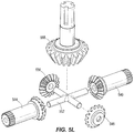
- FIGS. 5A-L are front, back, and perspective views of the mechanical averaging differential gearbox.
- FIG. 6 is a perspective view of the gauge wheel arms and an over-the-shaft position sensor coupled to a pivot shaft for the gauge wheel arms.
- FIG. 9 is a perspective view of the gauge wheel arms and a position sensor that includes accelerometers coupled to the gauge wheel arms.
- FIG. 10 is a side view of one of the gauge wheels, as well as a position sensor that detects an edge of the side wheel.
- FIG. 11 is a perspective view of one of the gauge wheel arms, as well as a position sensor in the form of an assembly that includes a sensing element and a sensed surface.
- FIG. 11A is a schematic illustration of a compensation system for a position sensor.
- FIG. 12 is a graphical representation of the output of the position sensor of FIG. 11 .
- FIG. 13 is a schematic view of a sensor for measuring wear on a blade of a seeding machine.
- FIG. 1 illustrates a seeding machine 10 (e.g., a row crop planter).
- the seeding machine 10 includes a main frame 14 .
- a plurality of individual row units 18 are coupled (e.g., mounted) on a rear portion of the main frame 14 , such that the row units 18 are pulled over a layer of soil 20 .
- the row units 18 may be positioned forward of the frame 14 and are pushed over the soil layer, or the machine may have a combination of push and pull row units 18 .
- Seed sources such as storage tanks 22 a - 22 c are coupled to the main frame 14 , and hold seed that is delivered, e.g., pneumatically or in any other suitable manner, to a mini-hopper (not shown) associated with each row unit 18 .
- the storage tanks 22 a - 22 c are coupled to the mini-hoppers by way of conduits 26 , such as hoses, and a pressurized delivery apparatus (not shown).
- Each storage tank 22 a - 22 c contains the same or different varieties of seed to be planted in the soil 20 .
- Each row unit 18 is connected to a conduit 26 such that each row unit 18 is coupled to a storage tank 22 a - 22 c to receive seed.
- each row unit 18 further includes its own sub-frame 30 , to which various components (e.g., a furrow opener, a furrow closer, etc.) are mounted.
- FIG. 2 illustrates an example of a row unit 118 that may be used in place of one of the row units 18 in FIG. 1 . Similar to the row unit 18 , the row unit 118 is also coupled to the main frame 14 . In some constructions, a plurality of row units 118 are coupled to the main frame 14 , similar to the row units 18 in FIG. 1 .
- each row unit 118 includes hoppers 122 a , 122 b , which hold chemical and seed, respectively (as opposed to the row unit 18 receiving seed from bulk storage as in the construction illustrated in FIG. 1 ).
- the hoppers 122 a , 122 b are coupled to a row unit sub-frame 130 .
- Each row unit 118 also includes a gauge wheel or wheels 132 coupled to the row unit sub-frame 130 .
- the gauge wheel 132 contacts and rolls along the soil 20 , and a furrow opener 134 (e.g., an opening wheel or blade or other structure having a stationary or rotating surface that contacts and moves soil away to form a furrow) is coupled to the row unit sub-frame 130 for forming a furrow 136 (illustrated schematically) in the soil 20 .
- a seed metering device 138 coupled to the row unit sub-frame 130 receives seeds from the hopper 122 b and meters and dispenses the seeds into the furrow 136 .
- a furrow closer 140 (e.g., a closing and packing wheel or wheels or other structure having a stationary or rotating surface that contacts and presses soil 20 ) coupled to the row unit sub-frame 130 pushes soil around the seeds to close the furrow 136 (see FIG. 1 ).
- Each row unit 118 may also include a seed firmer 144 (e.g. an angled arm as illustrated in FIG. 2 , a press wheel coupled to a press wheel arm, or other structure that firms a seed) coupled to the row unit sub-frame 130 that firms each seed and pushes it into the open furrow 136 to ensure good seed to soil contact before the furrow 136 is closed.
- each row unit 118 also includes at least one depth sensor in the form of a position sensor 148 (illustrated schematically) that is used to determine a depth 154 of the furrow 136 .
- the depth 154 is measured from a top surface 158 of the soil 20 to a bottom 162 of the furrow 136 , along a direction that is perpendicular to the top surface 158 (assuming a flat, non-inclined top surface 158 ).
- the depth 154 is equivalent to a distance between a bottom of the gauge wheel or wheels 132 and a bottom of the furrow opener 134 .
- one or more of the position sensors 148 described herein detects positions of the gauge wheel arm 166 (e.g., relative to the sub-frame 130 ).
- the position sensor or sensors 148 detect the positions of the gauge wheel arm 166 by detecting rotational movement of the gauge wheel arm 166 relative to the sub-frame 130 .
- the illustrated row unit 118 includes two gauge wheel arms 166 .
- the gauge wheel arms 166 are pivotally coupled to the sub-frame 130 .
- Each gauge wheel arm 166 is coupled to one gauge wheel 132 , such that rotation of each of the gauge wheel arms 166 changes a position of each of the gauge wheels 132 relative to the sub-frame 130 and thus relative to the opener 134 .
- each of the gauge wheel arms 166 rotates about a pivot axis 170 .
- a downforce is applied to the row unit 118 (e.g., with a downforce adjustment mechanism 174 ) the downforce pushes the row unit 118 and consequently the furrow opener 134 into the soil 20 to dig the furrow 136 .
- the gauge wheels 132 however continue to ride along the top surface 158 of the soil 20 .
- the depth 154 of the furrow 136 therefore depends on a position of the gauge wheels 132 relative to the furrow opener 134 , and the position of the gauge wheels 132 depends on a rotational position of the gauge wheel arms 166 relative to the sub-frame 130 .
- signals from the position sensor or sensors 148 are sent to a controller 178 , which calculates the depth 154 .
- the controller 178 when coupled to a global positioning system (GPS) signal processor, may generate a seed depth map and store that map for later analysis.
- GPS global positioning system
- a display 182 is also provided (e.g., in the operator cab 12 ), which displays (e.g., in real time) the depth 154 .
- the controller 178 may be positioned at various locations on seeding machine 10 .
- the controller 178 is positioned within the operator cab 12 , and signals are sent by wire or wirelessly from the position sensor or sensors 148 to the controller 178 .
- the position sensor or sensors 148 themselves includes a controller 178 .
- Other constructions include different locations for the controller 178 .
- stops 186 are also provided for each gauge wheel arm 166 to limit rotation of the gauge wheel arm 166 .
- the stops 186 may be adjusted to a desired position to set the depth 154 in the furrow 136 .
- the position of the stops 186 may be manually adjusted or a remote adjustment assembly may be included such as shown in U.S. Pat. No. 4,413,685, the entire contents of which are incorporated herein by reference.
- the gauge wheel arms 132 may not always be contacting the stops 186 , and thus the actual depth 154 may not be determined solely by knowing the position of the stops 186 .
- the furrow opener 134 may wear during use, altering the actual depth 154 .
- relying on the stops 186 alone is not sufficient to determine the actual depth 154 of the furrow 136 at any given time.
- one of the position sensors 148 a is coupled to one gauge wheel arm 166
- another position sensor 148 a is coupled to another gauge wheel arm 166 , to separately detect the rotational positions of each of the gauge wheel arms 166 relative to the sub-frame 130 .
- each of the position sensors 148 a is a rotary potentiometer with a linkage 190 coupled to the gauge wheel arm 166 .
- other constructions include different types of position sensors 148 a (e.g., ultrasonic, etc.), as well as different linkages 190 than that illustrated.
- the position sensors 148 a are illustrated as being positioned between and/or below the two gauge wheel arms 166 , and coupled to a bracket 192 of the sub-frame 130 , such that the position sensors 148 a are at least partially enclosed by the gauge wheels 132 (e.g., such that the position sensors 148 a are at least partially concealed from view between the gauge wheels 132 when viewing the row unit along an axis of rotation 149 of the gauge wheel 132 or wheels 132 , the axis of rotation 149 being illustrated in FIG. 5 ).
- the position sensors 148 a are disposed below at least a portion of the sub-frame 130 . However, other constructions include different locations for the position sensors 148 a .
- a controller e.g., the controller 178
- a single position sensor 148 b (illustrated schematically in FIG. 5 , and in detail in FIGS. 5A-5K ) is used to measure rotational positions of multiple gauge wheel arms 166 at the same time, and to average the rotational positions of the gauge wheel arms 166 . Taking an average measurement is useful, for example, when the two gauge wheels 132 are riding over uneven or inclined surfaces, and where one gauge wheel 132 may be lifted up or raised slightly relative to the other gauge wheel 132 .
- the position sensor 148 b includes a first link arm 504 and a second link arm 508 .
- the first link arm 504 and the second link arm 508 each generally have an S-shaped or curvilinear profile, although other constructions include differently shaped profiles.
- the position sensor 148 b further includes a third link arm 512 pivotally coupled to the first link arm 504 , and a fourth link arm 516 pivotally coupled to the second link arm 508 with pins 520 .
- the third link arm 512 and the fourth link arm 516 each generally have a linear shaped profile, although other constructions include differently shaped profiles.
- the third link arm 512 and the fourth link arm 516 are pivotally coupled to the gauge wheel arms 166 with pins 524 ( FIG. 5D ).
- the position sensor 148 b further includes a differential gearbox 528 ( FIG. 5D ) coupled to the first link arm 504 and the second link arm 508 .
- the differential gearbox 528 includes an outer housing 532 .
- the differential gearbox 528 further includes an inner housing 536 disposed within the outer housing 532 .
- the inner housing 536 has a cylindrical shape, although other constructions include different shapes than that illustrated.
- a first bevel gear 540 ( FIGS. 5B and 5C ) is coupled to the first link 504 and is disposed at least partially within the inner housing 536 .
- the first bevel gear 540 is coupled to the first link 504 via a spline connection, although other constructions include different connections.
- the first bevel gear 540 rotates with the first link 504 .
- a second bevel gear 544 ( FIGS. 5B and 5C ) is coupled to the second link 508 and is disposed at least partially within the inner housing 536 .
- the second bevel gear 544 is coupled to the second link 508 via a spline connection, although other constructions include different connections.
- the second bevel gear 544 rotates with the second link 508 .
- the first bevel gear 540 and the second bevel gear 544 each rotate about a common axis 546 ( FIG. 5A ).
- a third bevel gear 548 ( FIGS. 5A-5C ) is disposed at least partially within the inner housing 536 .
- the third bevel gear 548 is pivotally coupled to the inner housing 536 via a pin structure 552 .
- a fourth bevel gear 556 ( FIGS. 5A-5C ) is disposed at least partially within the inner housing 536 .
- the fourth bevel gear 556 is pivotally coupled to the inner housing 536 with the same pin structure 552 .
- the pin structure 552 also extends into the first bevel gear 540 and the second bevel gear 544 (i.e., forms a cross-shaped bevel gear support structure, as illustrated in FIG. 5L ).
- the third bevel gear 548 and the fourth bevel gear 556 each rotate about a second common axis 558 ( FIG. 5A ) that is perpendicular to the first common axis 546 .
- the first bevel gear 540 , the second bevel gear 544 , the third bevel gear 548 , and the fourth bevel gear 556 are each the same size.
- the position sensor 148 b further includes a ring gear 560 that is fixed to the inner housing 536 .
- the ring gear 560 is fixed to the inner housing with fasteners 564 , although in other constructions the ring gear 560 may be fixed in other manners, or may be integrally formed as a single piece with the inner housing 536 .
- the position sensor 148 b further includes a larger, fifth bevel gear 568 that engages with the ring gear 560 .
- the fifth bevel gear 568 is coupled to a single potentiometer 572 (illustrated schematically in FIG. 5A ).
- various other bearings, washers, and/or fasteners 576 are provided to complete the connections between the components described above, and to facilitate movement of the components as described further below.
- the row unit 18 travels along the surface of a field. If the field contains rocks, debris, or other obstacles, one of the gauge wheels 132 may ride up and over one of the obstacles. When the one gauge wheel 132 encounters the obstacle, the gauge wheel 132 rises, causing a rotation of the gauge wheel arm 166 . When the gauge wheel arm 166 rotates, the third link arm 512 rotates, causing rotation of the first link arm 504 .
- the position sensor 148 b senses an average position of the two gauge wheel arms 166 .
- the first link arm 504 in FIG. 5C is rotated out of the page (i.e., counterclockwise in FIG. 5C ) due to riding over the obstacle, the first bevel gear 540 rotates counterclockwise.
- the rotation of first bevel gear 540 will cause the third bevel gear 548 to rotate and to cause rotation of the pin structure 552 .
- the pin structure 552 is coupled to the housing 536 such that the pin structure 552 and the housing 536 rotate together, causing the ring gear 560 to rotate.
- the pin structure 552 only rotates half as much as the first bevel gear 540 so that the input into the potentiometer 572 is only half the gauge wheel arm 166 movement, and so that the input into the potentiometer 572 is therefore the average of the two gauge wheel arms 166 .
- first link arm 504 is rotated out of the page in FIG. 5C while the second link arm 508 is rotated in an opposite direction into the page, the first bevel gear 540 and the second bevel gear 544 will rotate in opposite directions, causing no rotation of the pin structure 552 and thus no change in the average position of the gauge wheel arms 166 .
- the position sensor 148 c is instead an over-the-shaft sensor (illustrated schematically) in the form of an angular position sensor in contact with (e.g., fixed) to a pivot shaft 198 .
- At least one of the gage wheel arms 166 pivots about the pivot shaft 198 .
- the pivot shaft 198 extends through a bearing section 200 of one of the gauge wheel arms 166 , with the pivot axis 170 extending through the pivot shaft 198 .
- the bearing section 200 is used to rotatably mount the gauge wheel arm 166 to the frame 130 for rotation about the pivot axis 170 (e.g., with the rest of the gauge wheel arm itself extending away from the bearing section 200 and toward the gauge wheel 132 and toward a gauge wheel mounting portion at the end of the gauge wheel arm 166 ).
- the over-the-shaft position sensor 148 d is a potentiometer that includes a linkage or other structure coupled to the gauge wheel arm 166 , although other constructions include different types of sensors for measuring the angular position of the gauge wheel arm 166 .
- a signal relating to the rotational position of the gauge wheel arm 166 is sent from the position sensor 148 c to the controller 178 to calculate the depth 154 .
- an over-the-shaft position sensor 148 c is provided for each gauge wheel arm 166 .
- the position sensor 148 d includes a single sensing array 202 positioned between the two gauge wheel arms 166 and fixed in place on the sub-frame 130 .
- the sensing array 202 includes for example a Hall Effect sensor(s) and/or a magneto-resistive sensor(s).
- the position sensor 148 d further includes a first magnet 206 coupled to (e.g., disposed on or within) one of the gauge wheel arms 166 , and a second magnet 210 coupled to the other gauge wheel arm 166 .
- the Hall Effect sensor(s) and/or magneto-resistive sensor(s) may be coupled to the gauge wheel arms 166 , and the magnet or magnets may be positioned between the two gauge wheel arms 166 on the sub-frame 130 .
- the sensing array 202 is illustrated as being positioned between the two gauge wheel arms 166 , such that the sensing array 202 is at least partially enclosed by the gauge wheels 132 , and disposed below at least a portion of the sub-frame 130 .
- other constructions include different locations for the position sensors 148 d.
- the first magnet 206 and the second magnet 210 pass by the sensing array 202 (e.g., without contacting the sensing array 202 ).
- the sensing array 202 detects the first magnet 206 and the second magnet 210 , and sends one or more signals to the controller 178 . Those signals are then used to determine a rotational position of each of the gauge wheel arms 166 relative to the sub-frame 130 , and/or to average the rotational positions of the gauge wheel arms 166 , and to then calculate the depth 154 .
- the sensing array 202 includes a single printed circuit board (PCB) that includes the Hall Effect sensor(s), and/or magneto-resistive sensor(s), and/or a microcontroller (e.g., the controller 178 or a separate controller that communicates with the controller 178 ).
- PCB printed circuit board
- the controller 178 or a separate controller that communicates with the controller 178 .
- more than one magnet is coupled to one of the gauge wheel arms 166 .
- Other sensor types may be used such as ultrasonic, optical, etc.
- some constructions of the seeding machine 10 also include a stop 186 .
- the stop 186 is shown in two different positions in each of FIGS. 7 and 8 , for illustrative purposes, demonstrating the adjustability of the stop 186 .
- the position sensor 148 e includes at least one accelerometer 214 coupled (e.g., mounted directly or otherwise directly coupled) to each gauge wheel arm 166 .
- the accelerometer position sensors 148 e determine the rotational positions of the gauge wheel arms 166 .
- the accelerometers 214 send signals (e.g., with wires or wirelessly) to the controller 178 , and the controller 178 calculates the depth 154 .
- the position sensor 148 f is a wheel edge sensor coupled to the sub-frame 130 and positioned to detect a position (e.g., height) of an edge 218 of one or more of the gauge wheels 132 . The position of the edge 218 is then used to calculate the depth 154 of the furrow 136 .
- the wheel edge position sensor 148 f is an optical sensor, a capacitive sensor, an ultrasonic sensor, a Hall Effect sensor, or a magneto-resistive sensor, although other constructions include different types of sensors (see for example the sensing elements 570 in U.S. Publication No. 2017/0086349, the entire contents of which are incorporated herein by reference).
- the edge 218 is the radially outward most edge of a metallic rim of the gauge wheel 132 .
- the edge 218 of the gauge wheel 132 includes at least one magnet or reflector, and the position sensor 148 f detects the magnet or reflector as it passes by the position sensor 148 f .
- the Hall Effect sensor, magneto-resistive sensor, or other sensor is coupled to the gauge wheel 132 , and a magnet or reflector is instead coupled to the sub-frame 130 .
- the controller 178 receives a signal from the position sensor 148 f relating to the edge 218 and determines a height of the gauge wheel 132 relative to the sub-frame 130 . As illustrated in FIG.
- the wheel edge position sensor 148 f is or forms part of a vertical structure positioned adjacent the edge 218 of the gauge wheel 132 .
- one wheel edge position sensor 148 f is positioned adjacent each gauge wheel 132 to separately measure the position of each gauge wheel 132 .
- signals from the wheel edge position sensors 148 f are sent to the controller 178 (e.g., to be averaged together to calculate a single measured depth 154 ).
- Other constructions include different shapes, sizes, and positions for the wheel edge position sensor 148 f than that illustrated.
- the edge 218 is an outer edge of the gauge wheel 132 .
- the position sensor 148 f may monitor other portions of the gauge wheel 132 .
- the gauge wheel 132 may include a radially inner metal portion having an outer rim, and an annular rubber or plastic tire portion coupled to the outer rim and surrounding the metal portion.
- the position sensor 148 f may detect the outer rim of the metal portion to detect wear of the metal portion.
- the row unit 118 may also include one or more additional sensors to detect and monitor wear of the rubber tire portion.
- the controller 178 may calibrate to take into account actual or anticipated wear of the rubber portion.
- the position sensor 148 g is an assembly that includes a sensing element 226 coupled to the sub-frame 130 (e.g., to a stationary shank of the sub-frame 130 ) which detects the distance between the sensing element 226 and a surface of the rotating gauge wheel arm 166 .
- the sensing element 226 is positioned on (e.g., fixed to) and carried by the sub-frame 130 .
- the gauge wheel arm 166 is formed with a sensing target surface 246 that varies non-linearly relative to the sensing element 226 .
- the sensing target surface 246 is eccentric relative to the gauge wheel pivot axis 170 (i.e., the sensing target surface 246 is a surface having an eccentricity greater than zero). In some constructions, the sensing target surface 246 forms a cam surface. As the gauge wheel arm 166 pivots, the distance between the sensing element 226 and the sensing target surface 246 changes. In some embodiments the sensing target surface 246 is machined into or otherwise integrally forms part of a raised shoulder portion or portions 203 of the bearing section 200 . Alternatively, the raised shoulder portion 203 is omitted and the sensing target surface 246 is formed in the generally cylindrical surface of the bearing section 200 . In another alternative, the sensing target surface 246 is formed on a sensor target clip (e.g., made of ferrous and/or non-ferrous material) that is releasably coupled to the bearing section 200 .
- a sensor target clip e.g., made of ferrous and/or non-ferrous material
- the sensing element 226 is a non-contact position sensor (e.g., an inductive proximity sensor, Hall Effect sensor, etc.) that detects a rotational position of the gauge wheel arm 166 .
- the sensing element 226 is positioned so as to be at least partially enclosed by the gauge wheels 132 , and disposed below at least a portion of the sub-frame 130 .
- the sensing element 226 includes a sensing portion 234 having at least one sensing surface (e.g., lower planar surface) that directly faces the sensing target surface 246 of the gauge wheel arm 166 . As illustrated in FIG.
- a three-dimensional projection 238 of the sensing surface bounded by an outer perimeter of the sensing portion 234 extends normally away from the sensing surface toward and perpendicular to the pivot axis 170 , such that the pivot axis 170 extends through the three-dimensional projection 238 .
- the dashed-line arrows illustrated in FIG. 11 represent the three-dimensional projection 238 extending away from the sensing portion 234 and passing through the bearing section 200 , thus crossing paths with the pivot axis 170 . It is noted, however, that in use the sensing portion 234 detects only the sensing target surface 246 itself. Thus, the portion of the projection 238 extending past the sensing target surface 246 in FIG. 11 is provided only to illustrate a position of the projection 238 relative to the pivot axis 170 .
- the sensing target surface 246 is sensed by the sensing element 226 , which determines a proximity of the sensing target surface 246 .
- the sensing target surface 246 is defined by a tapering thickness 242 on the raised shoulder portion 203 . As illustrated in FIG. 11 , the thickness 242 a at a first portion 250 of the raised shoulder portion 203 is less than a thickness 242 b at a second portion 254 of the raised shoulder portion 203 .
- a distance (i.e., gap) 258 between the sensing target surface 246 and the sensing element 226 decreases linearly as the gauge wheel arm 166 rotates counterclockwise about the pivot axis 170 (i.e., as the gauge wheel arm 166 lowers).
- the thickness 242 continuously increases moving clockwise around the sensing target surface 246 , such that when the sensing target surface 246 rotates counterclockwise with the gauge wheel arm 166 , the distance 258 continuously decreases.
- the distance 258 is directly proportional to an angle of the gage wheel arm 166 , and hence a depth of the furrow 136 .
- the distance 258 increases (representing a raising of the gauge wheel arm 166 )
- the depth of the furrow 136 also increases.
- the depth of the furrow 136 also decreases.
- FIG. 12 illustrates an example of a relationship between a measured output of the sensing element 226 and the depth of the furrow 136 , using a linear regression model.
- the sensing target surface 246 (or a plane tangent thereto) is parallel to the sensing surface (or a plane tangent thereto) of the sensing portion 234 in a least one position of the gauge wheel arm 166 (e.g., as the gauge wheel arm 166 rotates, a tangency (i.e., a line or a plane tangent to the curve) of the sensing target surface 246 remains parallel to the sensing surface).
- This parallel arrangement facilitates detection of the sensing target surface 246 by the sensing portion 234 of the sensing element 226 .
- the sensing target surface 246 (or a plane tangent thereto) is parallel to a corresponding portion of the sensing surface of the sensing portion 234 at all points during rotation of the gauge wheel arm 166 .
- One advantage of forming the gauge wheel arm 166 with the sensing target surface 246 (or otherwise attaching the sensing target surface 246 to the gauge wheel arm 166 ) is that the sensing element 226 thereby measures an actual gauge wheel arm 166 position (and not, for example, just the position of a gauge wheel arm stop).
- another sensing target surface 260 is disposed along an opposite side of the bearing section 200 , opposite a grease zurk 261 . This enables the gauge wheel arm 166 to be used on either side of the row unit 118 .
- FIG. 11A schematically illustrates a compensation system 300 for a position sensor.
- the system 300 is illustrated in the context of FIG. 11 , and is used for example to provide position and temperature compensation for a position sensor 148 h , which may be the same as position sensor 148 g shown in FIG. 11 , although the system 300 may be used to provide compensation for other position sensors (e.g., any of the position sensors described herein).
- the system 300 includes the position sensor 148 h , which may be in the form of position sensor 148 g described above, and the associated sensing element 226 coupled to (e.g., fixed to) the sub-frame 130 .
- the position sensor 148 h is a non-contact, analog inductive proximity sensor.
- Other constructions include different types of sensors.
- the system 300 also includes a target element 304 in the form of a sensor target clip (e.g., ferrous metal clip).
- the target element 304 is clipped, for example, or otherwise coupled over the end of the gauge wheel arm 166 , and includes a sensing target surface similar to the sensing target surface 246 illustrated in FIG. 11 that is detected by the position sensor 148 h , and may optionally include a sensing target surface similar to the sensing target surface 260 of FIG. 11 .
- the target surface 246 may be eccentric relative to the gauge wheel pivot axis 170 (e.g., such that a distance between the position sensor 148 h and the target surface 246 changes as the gauge wheel arm 166 rotates).
- the target element 304 instead is a raised shoulder portion of the gauge wheel arm 166 , and/or is integrally formed as a single piece with the gauge wheel arm 166 .
- the target element 304 includes a projection 312 extending away from an outer surface 314 of the target element 304 .
- the projection 312 extends away from the target surface 246 .
- the projection 312 is spaced adjacent to the target surface 246 .
- the projection 312 may take a variety of forms, including a rib, protrusion, spike, rod, thin plate, rectangular bar, etc.
- the projection 312 extends perpendicular to the outer surface 314 of the target element 304 , or substantially perpendicular to the outer surface 314 .
- the projection 312 is integrally formed as a single piece with the target element 304 .
- the gauge wheel arm 166 extends along a longitudinal axis, and the longitudinal axis extends through the projection 312 (e.g., when the sensor target clip is coupled to the end of the gauge wheel arm 166 ).
- Other constructions include various other numbers, locations, sizes, and shapes for the projection 312 than that illustrated.
- the system 300 further includes a compensation sensor 316 .
- the compensation sensor 316 is coupled (e.g., fixed to) the sub-frame 130 .
- the compensation sensor 316 includes a sensing element 320 that detects the projection 312 .
- the sensing element 320 is a non-contact position sensor (e.g., magnetic field sensor, gear-tooth sensor, inductive proximity sensor, back biased Hall Effect sensor, etc.).
- the seeding machine 10 is configured to rest on a ground surface, and the projection 312 is configured to extend vertically away from the ground surface when the projection 312 is detected by the compensation sensor 316 .
- the projection 312 includes a leading edge 324 (e.g., an edge extending perpendicular or substantially perpendicular to the outer surface of the target element 304 , and/or forming a rapidly rising surface that extends toward the sensing element 320 ).
- the sensing element 320 is configured to detect when the leading edge 324 is directly below, or in proximity to, the sensing element 320 , and/or when the leading edge 324 is moving past the sensing element 320 .
- Other constructions include different types of sensors than that illustrated for the compensation sensor 316 , as well as sensors that detect different surfaces or areas of the projection 312 than the leading edge 324 .
- the system 300 further includes a controller 328 (e.g., having a processor, memory, etc.).
- the controller 328 is coupled to both the position sensor 148 h and to the compensation sensor 316 , and is programmed with knowledge of the predetermined distance or angle.
- each sensor 148 h , 316 may include its own associated (e.g., integrated) controller.
- the controller 328 is programmed to receive a signal or signals from the compensation sensor 316 in response to the compensation sensor 316 detecting the projection 312 (e.g., detecting the leading edge 324 ).
- the controller 328 is also programmed to receive a signal or signals from the position sensor 148 as the gauge wheel arm 166 is rotating.
- the controller 328 is disposed in a cab of the seeding machine 10 , or on the sub-frame 130 .
- the compensation sensor 316 and the projection 312 are used to establish a zero reference position of the gauge wheel arm 166 , and to re-reference or re-calibrate the position sensor 148 h and/or the controller 324 .
- the compensation sensor 316 is used to detect the projection 312 when the seeding machine 10 is in, or only in, an inactive state (e.g., when the seeding machine 10 and/or the row unit 18 has been raised off of the ground). In this condition, the gauge arms 132 are hanging down, and the projection 312 is directly below the compensation sensor 316 (e.g., as illustrated in FIG. 11A ).
- the seeding machine 10 is moving along a field, for example, and the gauge wheel arm 166 is rotating within a range of motion (e.g., within a 20 degree range, within a 30 degree range, etc. about the pivot axis 170 ) that does not place the projection 312 within detection range of the compensation sensor 316 .
- a range of motion e.g., within a 20 degree range, within a 30 degree range, etc. about the pivot axis 170 .
- the compensation sensor 316 detects the projection 312 (e.g., detects the leading edge 324 )
- the compensation sensor 316 sends a signal to the controller 324 (e.g., indicating an absolute position of the target element 304 relative to the position sensor 148 h ).
- the controller 324 knows the fixed distance and/or angle between the position sensor 148 h and the compensation sensor 316 , the controller 324 is able to re-reference, or re-calibrate the controller 324 (or to re-reference or re-calibrate the controller position sensor 148 h itself). This re-referencing, or re-calibration, effectively removes effects from temperature drifts, run out, wear, etc.
- the controller 324 is able to re-set a zero reference position of the gauge wheel arm 166 relative to the position sensor 148 h .
- the controller 328 can then use this re-set zero reference position to determine how far the gauge wheel arm 166 later rotates relative to the re-set zero reference position.
- the seeding machine 10 and/or row unit 18 can then again be raised off of the ground, and the compensation sensor 316 can be used again a second time to re-calibrate the controller 324 and establish a re-set zero reference position.
- the system 300 may be used on other machines, including tillage machines, mower decks, construction and forestry machines, harvesters, or other machines (e.g., agricultural or industrial) that use a pivoting arm or other implement (e.g., similar to the pivoting gauge wheel arm 166 ).
- the system 300 may be used on soil tillage machines, vertical tillage machines, deep tillage machines, row crop cultivators, field cultivators, wheeled harvesters, loaders, bunchers, or various other machines.
- the compensation sensor 316 may be used to re-reference or re-calibrate a position sensor that is detecting an angular position of the pivoting arm or other implement.
- the position sensor(s) 148 described above are first calibrated before any measurements or calculations are made, and are subsequently re-calibrated one or more times after extensive use of the seeding machine 10 (e.g., once the furrow opener 134 begins to wear).
- the position sensors 148 described above detect rotational positions of the gauge wheel arm or arms 166 .
- those rotational positions must be compared with known rotational positions of the gauge wheel arms 166 when the depth 154 of the furrow 136 is considered zero.
- the row unit 118 may first be placed for example on a flat, hard surface (e.g., concrete), such that a bottom of the furrow opener 134 and bottoms of the gauge wheels 132 are all in contact with the concrete.
- the rotational positions of the gauge wheel arms 166 are then measured. Those measurements may then be used by the controller 178 to determine changes in the rotational positions of the gauge wheels 132 during operation, and to thereby fully calculate the depth 154 .
- the position sensor or sensors 148 the actual depth 154 may be determined on a continuous basis.
- the position sensor 148 output signals may also or alternatively be used as a diagnostic tool. For example, if a gauge wheel 132 remains in the same position for an extended (e.g., predetermined) period of time, this may indicate a malfunction on the row unit 118 that is holding the gauge wheel 132 in place. Likewise, loss of a gauge wheel 132 (i.e., a missing gauge wheel 132 that is no longer coupled to the gauge wheel arm 166 ) may be indicated by the signals. While this is rare, loss of a gauge wheel 132 may otherwise be undetected for a long time.
- the position sensor 148 may provide output signals that are used to indicate if the first gauge wheel arm 166 is out of an expected position by a predetermined magnitude or for a predetermined duration of time (e.g., the gauge wheel arm 166 is stuck and remaining in the same position) or is oscillating greater than a predetermined frequency about its pivot axis 170 (e.g., indicating further downforce may be needed to control or stabilize the gauge wheel arm 166 ), or if a differential between the two gauge wheels arms 166 is equal to or greater than a predetermined threshold and/or equal to or greater than a predetermined threshold for a predetermined amount of time (e.g., indicating that the two gauge wheel arms 166 are concurrently at different rotational positions for too great of a period of time).
- the row unit 118 includes at least one further position sensor 150 positioned on or adjacent the seed firmer 144 .
- the further position sensor 150 measures a rotational position of the seed firmer 144 relative to the sub-frame 130 (e.g., by detecting rotational movement of the seed firmer 144 relative to the sub-frame 130 ).
- the seed firmer 144 is rigid is coupled to the sub-frame 130 via a four-bar pivoting linkage 222 (see for example U.S. Patent Publication No. 2017/0086360 and U.S. Patent Publication No. 2017/0086362, both of which are incorporated in their entireties herein, for examples of four-bar pivoting linkages).
- Other seed firmers 144 may include a single rigid bar or pivoting arm, and/or may include a pressing wheel to firm the seeds.
- the further position sensor 150 may be a potentiometer, accelerometer, or other sensor positioned on the seed firmer 144 (e.g., on the four-bar pivoting linkage 222 ).
- the further position sensor 150 measures a rotational position of the four-bar pivoting linkage 222 relative to the sub-frame 130 .
- the further position sensor 150 may be any of a number of different types of sensors, including the types of sensors described above in conjunction with determining the rotational positions of the gauge wheel arms 166 .
- the further position sensor 150 may include a rotary potentiometer coupled to the seed firmer 144 (or four-bar linkage) and to the sub-frame, or may include any other rotary sensor coupled to a pivot point of the seed firmer 144 .
- the further position sensor 150 may include an over-the-shaft type of sensor, for example if the seed firmer 144 is of a type that pivots about a shaft.
- the further position sensor 150 may include a sensing array coupled to the sub-frame 130 or seed firmer 144 , and one or more magnets coupled to the seed firmer 144 or sub-frame 130 to detect the rotational position of the seed firmer 144 .
- the further position sensor 150 may include an accelerometer coupled to the seed firmer 144 .
- the position sensor or sensors 148 used to detect the rotational positions of the gauge wheel arms 166 are different types of sensors than the further position sensor 150 used to detect movement of the seed firmer 144 .
- the signal or signals from the further position sensor 150 are sent to the controller 178 , along with the signal or signals from the position sensor or sensors 148 associated with the gauge wheel arms 166 .
- the signals from these various position sensors 148 , 150 indicate both a rotational position of the seed firmer 144 relative to the sub-frame 130 and a rotational position of the gauge wheels 132 relative to the frame.
- the controller 178 may continuously calculate the depth 154 without having to calibrate or re-calibrate the position sensors 148 . This represents an actual depth measurement by analysis of the positions of a furrow following device (e.g., the seed firmer) and of a ground following device (e.g., the gauge wheel 132 ), each relative to the sub-frame 130 .
- the seeding machine 10 includes a sensor 262 (illustrated schematically) for measuring wear on the furrow opener 134 (or other blade on the seeding machine 10 ).
- the sensor 262 is an inductive proximity sensor coupled to the row unit 118 or other structure, although other constructions include different sensors (e.g., infrared, RF, optical, capacitive, etc.).
- the sensor 262 faces the furrow opener 134 (i.e., in a direction into the page in FIG. 13 ) and a shank 266 on the sub-frame 130 .
- the senor 262 and/or shank 266 may be located elsewhere (e.g., the sensor 262 may be located on the shank 266 and may look out toward the furrow opener 134 ). In some constructions the sensor 262 is positioned to generally be free of dirt, moisture, etc., and is coupled to the sub-frame 130 .
- the sensor 262 detects a predetermined portion of the furrow opener 134 (which is metallic in the illustrated construction). As the furrow opener 134 wears over time (e.g., to a diameter represented by the broken line 268 in FIG. 13 ), less of the furrow opener 134 is within a detectable region or projection of the sensor 262 . Thus, the inductive response in the sensor 262 decreases with an increasing degree of furrow opener 134 wear.
- the furrow opener 134 includes a disk blade, and the sensor 262 is a disk blade wear sensor that provides wear indication directly to an operator.
- the sensor 262 may be mounted, for example, perpendicularly to the disk blade to detect an effective disk blade radius (i.e., to detect a reduction in an outer portion of the disk blade after wear of the disk blade, thus representing how a radius of the disk blade has been reduced).
- the senor 262 may also or alternatively be used to monitor the quality of an outer edge of the furrow opener 134 (e.g., to detect roundness of the furrow opener 134 , dents in the edge caused by rock strikes, etc.).
- the senor 262 is coupled to a controller (e.g., the controller 178 ) to receive signals from the sensor 262 . Signals from the sensor 262 corresponding to the level of wear of the furrow opener 134 may be used by the controller to control one or more elements on the seeding machine 10 (e.g., depth adjustment mechanisms such as a support adjustment bar and support roller like the support adjustment bar 62 and the support roller 72 in U.S. Pat. No. 4,413,685, or other stop members or mechanisms for setting a depth adjustment on a planting machine).
- the sensor 262 and/or the controller 178 are coupled to a display that displays wear of the furrow opener 134 (e.g., to an operator during use of the seeding machine 10 ). In some constructions, the controller 178 provides an alert if the furrow opener 134 wears beyond a predetermined amount.
- the seeding machine 10 includes both the sensor 262 , as well as one or more of the position sensors 148 described above. Similar to the sensor 262 , the sensor or sensors 148 may be coupled to a controller (e.g., the controller 178 ). The controller 178 monitors signals from the sensors 262 , 148 to determine both an amount of wear on the furrow opener 134 (or other blade(s) on the seeding machine 10 ) as well as movement of the gauge wheel arms 166 . This information is then used together to determine a depth of the furrow 136 and/or to control one or more elements on the seeding machine 10 .
- a controller e.g., the controller 178
- the controller 178 monitors signals from the sensors 262 , 148 to determine both an amount of wear on the furrow opener 134 (or other blade(s) on the seeding machine 10 ) as well as movement of the gauge wheel arms 166 . This information is then used together to determine a depth of the furrow 136 and/or to control one or more elements
- one or more of the position sensors 148 are first calibrated before any measurements or calculations are made, and are subsequently re-calibrated one or more times after extensive use of the seeding machine 10 (e.g., once the furrow opener 134 begins to wear).
- the sensor 262 By using the sensor 262 , such re-calibration, or normalization, following the initial calibration is no longer required, since the wear of the furrow opener 134 is accounted for via the measurements from the sensor 262 (i.e., the sensor 262 is used for calibration or normalization).
- the controller 178 may assume that the furrow opener 134 has not worn, and that the furrow opener 134 is therefore penetrating into the furrow 134 in a consistent, identical manner with each use of the seeding machine 10 .
- the controller 178 may assume also that a particular depth of the furrow 136 is being achieved based solely on a measured angle of the gauge wheel arms 166 . With the additional use of the sensor 262 , however, the controller 10 is able to take into account and compensate for wear of the furrow opener 134 .
- this information may be evaluated by the controller 178 (e.g., used as an offset or compensation value after measuring the gauge wheel arm 166 positions with the positions sensor or sensor 148 ) when determining the actual depth of the furrow 136 .
- the seeding machine 10 may include any one or more of the positions sensors, or a combination thereof. Additionally, any of the sensors (e.g., position sensors) described herein may be disposed between the gauge wheel arms and/or under at least a portion of the frame, and in some constructions one or more features of the sensors (e.g., the potentiometer, differential gearbox, sensing array, etc.) may be at least partially concealed from view between the gauge wheel arms when viewing the seeding machine along an axis of rotation of one of the gauge wheels.
- the seeding machine 10 may use at least one controller, such as the controller 178 , to receive signals from any of the position sensors described herein, and to use those signals to control one or more elements on the seeding machine 10 and/or to perform calculations relating to the seeding machine 10 (e.g., corresponding to furrow depth, positioning of components, etc.).
- the controller 178 may use at least one controller, such as the controller 178 to receive signals from any of the position sensors described herein, and to use those signals to control one or more elements on the seeding machine 10 and/or to perform calculations relating to the seeding machine 10 (e.g., corresponding to furrow depth, positioning of components, etc.).
- a seeding machine comprising a frame, a first gauge wheel arm pivotally coupled to the frame, a first gauge wheel coupled to the first gauge wheel arm, a second gauge wheel arm pivotally coupled to the frame, a second gauge wheel coupled to the second gauge wheel arm, and a depth sensor coupled to both the first gauge wheel arm and the second gauge wheel arm, the depth sensor including a differential gearbox and a single potentiometer.
- the depth sensor includes a first link coupled to the first gauge wheel arm and a second link coupled to the second gauge wheel arm
- the differential gearbox includes a housing, a first bevel gear coupled to the first link and disposed at least partially within the housing, a second bevel gear coupled to the second link and disposed at least partially within the housing, a third bevel gear coupled to and disposed within the housing, and a fourth bevel gear coupled to and disposed within the housing, wherein the first bevel gear, the second bevel gear, the third bevel gear, and the fourth bevel gear are in engagement with one another such that rotational movement of the first gauge wheel arm causes an equal and opposite rotational movement of the second gauge wheel arm.
- Clause 7 The seeding machine of clause 1, further comprising a controller in communication with the depth sensor, wherein the depth sensor outputs signals corresponding to positions of the gauge wheel arms, and wherein the controller is configured to provide an alert if one of the gauge wheel arms is missing or if one of the gauge wheel arms has remained in a same position for a predetermined period of time.
- a seeding machine comprising a frame, a gauge wheel arm pivotally coupled to the frame, a gauge wheel coupled to the gauge wheel arm, and a position sensor assembly configured to detect a rotational position of the gauge wheel arm, the position sensor assembly including an eccentric surface.
- the gauge wheel arm includes a bearing section having a raised shoulder portion with a tapered thickness, the raised shoulder portion defining the eccentric surface such that as the gauge wheel arm pivots relative to the frame, a distance between the inductive proximity sensor and the eccentric surface changes.
- Clause 16 The seeding machine of clause 8, wherein the seeding machine includes a furrow opener, and wherein the position sensor assembly includes a sensor to detect wear of the furrow opener.
- Clause 17 The seeding machine of clause 8, further comprising a controller in communication with the position sensor assembly, wherein the position sensor assembly provides outputs signals corresponding to a position of the gauge wheel arm, and wherein the controller is configured to provide an alert if the gauge wheel arm is missing or the gauge wheel arm has remained in a same position for a predetermined period of time.
- Clause 25 The seeding machine of clause 18, further comprising a controller in communication with the position sensor, wherein the position sensor outputs signals corresponding to a position of the first gauge wheel arm, and wherein the controller is configured to provide an alert if the first gauge wheel arm is missing or if the first gauge wheel arm has remained in a same position for a predetermined period of time
- a seeding machine comprising a frame. a first gauge wheel arm pivotally coupled to the frame, a first gauge wheel coupled to the first gauge wheel arm, a second gauge wheel arm pivotally coupled to the frame, a second gauge wheel coupled to the second gauge wheel arm, and a position sensor assembly having a position sensor disposed between the first gauge wheel arm and the second gauge wheel arm such that the position sensor is at least partially concealed from view between the first and second gauge wheels when viewing the seeding machine along an axis of rotation of the first gauge wheel.
- Clause 31 The seeding machine of clause 26, wherein the seeding machine includes a furrow opener, and wherein the position sensor assembly includes a sensor to detect wear of the furrow opener.
- Clause 32 The seeding machine of clause 26, further comprising a controller in communication with the position sensor, wherein the position sensor outputs signals corresponding to a position of the first gauge wheel arm, and wherein the controller is configured to provide an alert if the first gauge wheel arm is missing or if the first gauge wheel arm has remained in a same position for a predetermined period of time.
- a seeding machine comprising a frame, a furrow opener coupled to the frame, a first gauge wheel arm pivotally coupled to the frame, a first gauge wheel coupled to the first gauge wheel arm, a second gauge wheel arm pivotally coupled to the frame, a second gauge wheel coupled to the second gauge wheel arm, and a position sensor assembly having a first position sensor to detect a rotational movement of the first gauge wheel arm, the position sensor assembly further including a second position sensor to detect wear of the furrow opener.
- Clause 34 The seeding machine of clause 33, wherein the first position sensor is configured to detect a rotational movement of both the first gauge wheel arm and the second gauge wheel arm.
- the position sensor assembly includes a controller, wherein the controller is configured to receive signals from both the first position sensor and the second position sensor, and to use the signals to determine a depth of a furrow.
- Clause 37 The seeding machine of clause 36, wherein the controller is configured to provide an alert if one of the gauge wheel arms is missing or if one of the gauge wheel arms has remained in a same position for a predetermined period of time.
- a seeding machine comprising a frame, a first gauge wheel arm pivotally coupled to the frame, a first gauge wheel coupled to the first gauge wheel arm, a second gauge wheel arm pivotally coupled to the frame, a second gauge wheel coupled to the second gauge wheel arm, and a position sensor assembly having a position sensor to detect a rotational movement of the first gauge wheel arm, and a controller in communication with the position sensor, wherein the position sensor outputs signals corresponding to a position of the gauge wheel arm, and wherein the controller is configured to provide an alert if the first gauge wheel is missing or if the first gauge wheel arm has remained in a same position for a predetermined period of time.
- a seeding machine comprising a frame, a first gauge wheel arm pivotally coupled to the frame, a first gauge wheel coupled to the first gauge wheel arm, a second gauge wheel arm pivotally coupled to the frame, a second gauge wheel coupled to the second gauge wheel arm, and a position sensor assembly having a position sensor that includes a single sensing array positioned between the first gauge wheel arm and the second gauge wheel arm.
- Clause 50 The seeding machine of clause 44, further comprising a controller in communication with the position sensor, wherein the position sensor outputs signals corresponding to a position of the first gauge wheel arm, and wherein the controller is configured to provide an alert if the first gauge wheel arm is missing or if the first gauge wheel arm has remained in a same position for a predetermined period of time.
- a seeding machine comprising a frame, a first gauge wheel arm pivotally coupled to the frame, a first gauge wheel coupled to the first gauge wheel arm, a second gauge wheel arm pivotally coupled to the frame, a second gauge wheel coupled to the second gauge wheel arm, and a position sensor assembly having a position sensor that includes an accelerometer coupled to the first gauge wheel arm to measure movement of the first gauge wheel arm.
- Clause 55 The seeding machine of clause 51, wherein the seeding machine includes a furrow opener, and wherein the position sensor assembly includes a sensor to detect wear of the furrow opener.
- Clause 56 The seeding machine of clause 51, further comprising a controller in communication with the position sensor, wherein the position sensor outputs signals corresponding to a position of the first gauge wheel arm, and wherein the controller is configured to provide an alert if the first gauge wheel arm is missing or if the first gauge wheel arm has remained in a same position for a predetermined period of time.
- Clause 60 The seeding machine of clause 57, wherein the frame includes a shank, wherein the position sensor is coupled to the shank and faces away from the shank and toward the furrow opener.
- a seeding machine comprising a frame, a ground following device coupled to the frame. a furrow following device coupled to the frame, and a position sensor assembly having a first position sensor that detects movement of the ground following device and a second position sensor that detects movement of the furrow following device.
- Clause 64 The seeding machine of clause 62, wherein the seed firmer is coupled to the frame via a four-bar pivoting linkage.
- Clause 65 The seeding machine of clause 64, wherein the second position sensor is a rotary potentiometer coupled to the four-bar pivoting linkage and the frame.
Landscapes
- Life Sciences & Earth Sciences (AREA)
- Soil Sciences (AREA)
- Environmental Sciences (AREA)
- Engineering & Computer Science (AREA)
- Mechanical Engineering (AREA)
- Zoology (AREA)
- Sowing (AREA)
- Fertilizing (AREA)
Abstract
Description
Claims (15)
Priority Applications (4)
| Application Number | Priority Date | Filing Date | Title |
|---|---|---|---|
| US15/901,297 US11206754B2 (en) | 2018-02-21 | 2018-02-21 | Depth sensing with absolute position and temperature compensation |
| EP19152876.9A EP3530093B1 (en) | 2018-02-21 | 2019-01-21 | A compensation system for a position sensor of an agricultural machine |
| US17/557,979 US12022754B2 (en) | 2018-02-21 | 2021-12-21 | Depth sensing with absolute position and temperature compensation |
| US18/761,097 US20240349636A1 (en) | 2018-02-21 | 2024-07-01 | Depth sensing with absolute position and temperature compensation |
Applications Claiming Priority (1)
| Application Number | Priority Date | Filing Date | Title |
|---|---|---|---|
| US15/901,297 US11206754B2 (en) | 2018-02-21 | 2018-02-21 | Depth sensing with absolute position and temperature compensation |
Related Child Applications (1)
| Application Number | Title | Priority Date | Filing Date |
|---|---|---|---|
| US17/557,979 Division US12022754B2 (en) | 2018-02-21 | 2021-12-21 | Depth sensing with absolute position and temperature compensation |
Publications (2)
| Publication Number | Publication Date |
|---|---|
| US20190254222A1 US20190254222A1 (en) | 2019-08-22 |
| US11206754B2 true US11206754B2 (en) | 2021-12-28 |
Family
ID=65138929
Family Applications (3)
| Application Number | Title | Priority Date | Filing Date |
|---|---|---|---|
| US15/901,297 Active 2038-07-23 US11206754B2 (en) | 2018-02-21 | 2018-02-21 | Depth sensing with absolute position and temperature compensation |
| US17/557,979 Active 2038-06-02 US12022754B2 (en) | 2018-02-21 | 2021-12-21 | Depth sensing with absolute position and temperature compensation |
| US18/761,097 Pending US20240349636A1 (en) | 2018-02-21 | 2024-07-01 | Depth sensing with absolute position and temperature compensation |
Family Applications After (2)
| Application Number | Title | Priority Date | Filing Date |
|---|---|---|---|
| US17/557,979 Active 2038-06-02 US12022754B2 (en) | 2018-02-21 | 2021-12-21 | Depth sensing with absolute position and temperature compensation |
| US18/761,097 Pending US20240349636A1 (en) | 2018-02-21 | 2024-07-01 | Depth sensing with absolute position and temperature compensation |
Country Status (2)
| Country | Link |
|---|---|
| US (3) | US11206754B2 (en) |
| EP (1) | EP3530093B1 (en) |
Cited By (6)
| Publication number | Priority date | Publication date | Assignee | Title |
|---|---|---|---|---|
| US11925137B2 (en) | 2019-03-08 | 2024-03-12 | Deere & Company | Planter row unit with load sensing depth stop assembly |
| US12022754B2 (en) | 2018-02-21 | 2024-07-02 | Deere & Company | Depth sensing with absolute position and temperature compensation |
| US12029146B2 (en) | 2019-10-30 | 2024-07-09 | Deere & Company | Implement having weight transfer system and method of operating the same |
| US12127497B2 (en) | 2019-03-05 | 2024-10-29 | Deere & Company | Planter row unit downforce control with ground view sensor |
| US12543626B2 (en) | 2022-04-21 | 2026-02-10 | Cnh Industrial America Llc | System and method for controlling row cleaner positioning on a seed-planting implement |
| US12582024B2 (en) | 2022-08-31 | 2026-03-24 | Cnh Industrial Canada, Ltd. | Sensor drift detection for a downforce control system of a seeding implement |
Families Citing this family (16)
| Publication number | Priority date | Publication date | Assignee | Title |
|---|---|---|---|---|
| US10939604B2 (en) * | 2018-10-01 | 2021-03-09 | Deere & Company | Multi-sensor tool height control for ground engaging tools |
| US11191204B2 (en) * | 2019-02-18 | 2021-12-07 | Cnh Industrial Canada, Ltd. | System and method for monitoring soil conditions within a field |
| US11343956B2 (en) * | 2019-02-18 | 2022-05-31 | Cnh Industrial Canada, Ltd. | System and method for monitoring soil conditions within a field |
| US11582899B2 (en) | 2019-12-24 | 2023-02-21 | Cnh Industrial America Llc | Particle delivery system of an agricultural row unit |
| US11589500B2 (en) | 2019-12-24 | 2023-02-28 | Cnh Industrial America Llc | Particle delivery system of an agricultural row unit |
| US11490558B2 (en) | 2019-12-24 | 2022-11-08 | Cnh Industrial America Llc | Particle delivery system of an agricultural row unit |
| US11523556B2 (en) | 2019-12-24 | 2022-12-13 | Cnh Industrial America Llc | Particle delivery system of an agricultural row unit |
| US11523555B2 (en) | 2019-12-24 | 2022-12-13 | Cnh Industrial America Llc | Particle delivery system of an agricultural row unit |
| US11483963B2 (en) | 2019-12-24 | 2022-11-01 | Cnh Industrial America Llc | Particle delivery system of an agricultural row unit |
| US11564344B2 (en) | 2019-12-24 | 2023-01-31 | Cnh Industrial America Llc | Particle delivery system of an agricultural row unit |
| US11553638B2 (en) | 2019-12-24 | 2023-01-17 | Cnh Industrial America Llc | Particle delivery system of an agricultural row unit |
| US11596095B2 (en) | 2019-12-24 | 2023-03-07 | Cnh Industrial America Llc | Particle delivery system of an agricultural row unit |
| US11564346B2 (en) | 2019-12-24 | 2023-01-31 | Cnh Industrial America Llc | Particle delivery system of an agricultural row unit |
| US11553639B2 (en) | 2019-12-24 | 2023-01-17 | Cnh Industrial America Llc | Particle delivery system of an agricultural row unit |
| US11516958B2 (en) | 2019-12-24 | 2022-12-06 | Cnh Industrial America Llc | Particle delivery system of an agricultural row unit |
| US20240324493A1 (en) * | 2023-03-27 | 2024-10-03 | Deere & Company | Gauge wheel linkage assembly |
Citations (36)
| Publication number | Priority date | Publication date | Assignee | Title |
|---|---|---|---|---|
| US2192948A (en) | 1939-03-25 | 1940-03-12 | Deere & Co | Planter |
| US4445923A (en) | 1982-12-30 | 1984-05-01 | Owens-Illinois, Inc. | Position sensing device |
| US4850454A (en) | 1988-07-29 | 1989-07-25 | Allied-Signal Inc. | Disc brake lining wear sensor |
| US5479992A (en) | 1993-07-27 | 1996-01-02 | Dawn Equipment Company | Agricultural implement controller to compensate for soil hardness variation |
| US5591945A (en) | 1995-04-19 | 1997-01-07 | Elo Touchsystems, Inc. | Acoustic touch position sensor using higher order horizontally polarized shear wave propagation |
| US6076611A (en) * | 1998-12-17 | 2000-06-20 | Agco Corporation | Implement mounted depth control system |
| US6216794B1 (en) | 1999-07-01 | 2001-04-17 | Andrew F. Buchl | Joystick control for an automatic depth control system and method |
| US20020174813A1 (en) | 2001-05-24 | 2002-11-28 | Hagny Matthew P. | Depth-limited furrow closing arrangement and method for no-till agricultural seeders |
| US20050155536A1 (en) | 2004-01-16 | 2005-07-21 | Wendte Keith W. | Tandem gauge wheel assembly for planting unit |
| US7360495B1 (en) | 2006-12-18 | 2008-04-22 | Howard D. Martin | Method for planter depth monitoring |
| WO2008086283A2 (en) | 2007-01-08 | 2008-07-17 | Precision Planting Inc. | Load sensing pin |
| EP2322026A1 (en) | 2009-11-17 | 2011-05-18 | Deere & Company | Row unit and planting machine with such row unit |
| US20110313575A1 (en) | 2010-06-22 | 2011-12-22 | Trevor Kowalchuk | Down Pressure Adjustment Device And Method For Use With A Disc Opener Assembly Of An Agricultural Implement |
| US20140048296A1 (en) | 2012-08-20 | 2014-02-20 | Dawn Equipment Company | Agricultural Apparatus For Sensing And Providing Feedback Of Soil Property Changes In Real Time |
| WO2014066650A1 (en) | 2012-10-24 | 2014-05-01 | Precision Planting Llc | Agricultural trench closing systems, methods, and apparatus |
| US20140116735A1 (en) | 2010-09-15 | 2014-05-01 | Dawn Equipment Compnay | Agricultural Systems |
| WO2014066654A1 (en) | 2012-10-24 | 2014-05-01 | Precision Planting Llc | Agricultural trench depth sensing systems, methods, and apparatus |
| US20140303854A1 (en) | 2013-04-08 | 2014-10-09 | Ag Leader Technology | On-the-go soil sensors and control methods for agricultural machines |
| US20150230391A1 (en) | 2014-02-19 | 2015-08-20 | Shane Houck | Depth control for a seed planting system |
| US20150237790A1 (en) | 2013-03-07 | 2015-08-27 | Blue River Technology, Inc. | System and method for automated odometry calibration for precision agriculture systems |
| EP3072763A1 (en) | 2015-03-25 | 2016-09-28 | Honeywell International Inc. | Brake disc stack wear measurement |
| US20160348529A1 (en) | 2015-06-01 | 2016-12-01 | Hamilton Sundstrand Corporation | Redundant speed summing actuators |
| US20170086349A1 (en) | 2015-09-30 | 2017-03-30 | Deere & Company | Agricultural planting depth sensor |
| US20170094894A1 (en) | 2015-10-02 | 2017-04-06 | Deere & Company | Controlling an agricultural vehicle based on sensed inputs |
| EP3213617A1 (en) | 2015-11-06 | 2017-09-06 | Vredo Beheer B.V. | Method, implement and system for introducing manure into the ground |
| US20170303465A1 (en) | 2012-08-10 | 2017-10-26 | The Climate Corporation | Systems and methods for control, monitoring and mapping of agricultural applications |
| US20170367251A1 (en) | 2016-06-28 | 2017-12-28 | Agco Corporation | Down force control to allow for easier depth adjustment |
| EP3300569A1 (en) | 2016-09-30 | 2018-04-04 | Deere & Company | Planter row unit furrow depth sensing apparatus |
| EP3300567A1 (en) | 2016-09-30 | 2018-04-04 | Deere & Company | Planter row unit furrow depth sensing apparatus |
| US20180092293A1 (en) * | 2016-09-30 | 2018-04-05 | Deere & Company | Planter row unit furrow depth sensing apparatus and method |
| US20180092289A1 (en) * | 2016-09-30 | 2018-04-05 | Deere & Company | Planter row unit furrow depth sensing apparatus and method |
| US20180092290A1 (en) * | 2016-09-30 | 2018-04-05 | Deere & Company | Planter row unit furrow depth sensing apparatus and method |
| US20180092288A1 (en) * | 2016-09-30 | 2018-04-05 | Deere & Company | Planter row unit furrow depth sensing apparatus and method |
| US20180114305A1 (en) | 2015-05-08 | 2018-04-26 | Precison Planting Llc | Work layer imaging and analysis for implement monitoring, control and operator feedback |
| US20180120082A1 (en) | 2016-10-27 | 2018-05-03 | Deere & Company | Time domain depth sensor |
| US20190124824A1 (en) * | 2017-10-31 | 2019-05-02 | Deere & Company | Method of managing planter row unit downforce |
Family Cites Families (38)
| Publication number | Priority date | Publication date | Assignee | Title |
|---|---|---|---|---|
| US4413685A (en) | 1979-12-11 | 1983-11-08 | Gremelspacher Philip E | Planter implement with adjusting position-display apparatus and system thereof |
| DE3430136C1 (en) | 1984-08-16 | 1986-04-24 | Amazonen-Werke H. Dreyer Gmbh & Co Kg, 4507 Hasbergen | Seed drill |
| US4915014A (en) | 1985-05-08 | 1990-04-10 | Deere & Company | Disk harrow hydraulic wing balancing system |
| US5201372A (en) | 1991-09-30 | 1993-04-13 | Deere & Company | Wing fold implement with hydraulic mode indicator |
| US6688244B1 (en) | 2002-08-08 | 2004-02-10 | Deere & Company | Product on demand delivery system |
| US7673570B1 (en) | 2008-12-01 | 2010-03-09 | Dawn Equipment Company | Row-clearing unit for agricultural implement |
| US8522889B2 (en) | 2010-08-30 | 2013-09-03 | Cnh America Llc | Agricultural implement with combined down force and depth control |
| US8544397B2 (en) | 2010-09-15 | 2013-10-01 | Dawn Equipment Company | Row unit for agricultural implement |
| US8634992B2 (en) | 2011-01-26 | 2014-01-21 | Precision Planting Llc | Dynamic supplemental downforce control system for planter row units |
| US9743578B2 (en) | 2011-04-27 | 2017-08-29 | Kinze Manufacturing, Inc. | Agricultural devices, systems, and methods for determining soil and seed characteristics and analyzing the same |
| EP2701482B1 (en) | 2011-04-27 | 2018-06-06 | Kinze Manufacturing, Inc. | Down and/or up force adjustment system |
| US8380356B1 (en) | 2012-06-12 | 2013-02-19 | Ag Leader Technology | Seeder downforce section control |
| US8863676B2 (en) | 2012-07-12 | 2014-10-21 | Deere & Company | Twin-row multiple variety planter and method of use |
| CA2879731C (en) | 2012-07-25 | 2021-04-20 | Precision Planting Llc | Systems, methods and apparatus for multi-row agricultural implement control and monitoring |
| LT3729933T (en) | 2012-07-25 | 2022-04-11 | Precision Planting Llc | Downforce control system on an agricultural implement |
| US9506750B2 (en) | 2012-09-07 | 2016-11-29 | Apple Inc. | Imaging range finding device and method |
| US20140076047A1 (en) | 2012-09-14 | 2014-03-20 | James Z. Liu | Tank commidity volume measurement apparatus and method |
| US9198343B2 (en) | 2013-07-12 | 2015-12-01 | Deere & Company | Implement weight transfer with feedback control |
| UA120259C2 (en) | 2013-11-08 | 2019-11-11 | Пресіжн Плентінг Елелсі | Implement weight management systems, methods, and apparatus |
| US10285323B2 (en) | 2013-11-13 | 2019-05-14 | Cnh Industrial America Llc | Agricultural tillage implement fold sequence control |
| US9848522B2 (en) | 2014-11-07 | 2017-12-26 | Dawn Equipment Company | Agricultural system |
| US9723778B2 (en) | 2014-11-07 | 2017-08-08 | Dawn Equipment Company | Agricultural system |
| US10582653B2 (en) | 2014-11-07 | 2020-03-10 | Dawn Equipment Company | Agricultural planting system with automatic depth control |
| US9826677B2 (en) | 2014-12-16 | 2017-11-28 | Cnh Industrial Canada, Ltd. | Seed implement incorporating a down pressure sensing and adjustment system |
| US9888624B2 (en) | 2015-06-30 | 2018-02-13 | Cnh Industrial America Llc | Individual row lift system for planters |
| US9839178B2 (en) | 2015-09-30 | 2017-12-12 | Deere & Company | Seed firmer |
| US9848527B2 (en) | 2015-09-30 | 2017-12-26 | Deere & Company | Furrow following device |
| US10091926B2 (en) | 2016-08-12 | 2018-10-09 | Deere & Company | Downforce sensing and control with acceleration correction |
| US9936631B1 (en) | 2016-09-30 | 2018-04-10 | Deere & Company | Device and method for detecting and reporting seed placement |
| US10928504B2 (en) | 2017-01-31 | 2021-02-23 | Kinze Manufactoring, Inc. | Radar based seed sensor for use with agricultural systems, methods, and apparatus |
| CA3194187A1 (en) | 2017-11-15 | 2019-05-23 | Precision Planting Llc | Seed trench closing sensors |
| WO2019118758A1 (en) | 2017-12-15 | 2019-06-20 | Kinze Manufacturing, Inc. | Systems, methods, and apparatus for controlling downforce of an agricultural implement |
| US11206754B2 (en) | 2018-02-21 | 2021-12-28 | Deere & Company | Depth sensing with absolute position and temperature compensation |
| US11202404B2 (en) | 2019-03-05 | 2021-12-21 | Deere & Company | Planter row unit downforce control with ground view sensor |
| US11134606B2 (en) | 2019-03-08 | 2021-10-05 | Deere & Company | Planter row unit with load sensing depth stop assembly |
| US12029146B2 (en) | 2019-10-30 | 2024-07-09 | Deere & Company | Implement having weight transfer system and method of operating the same |
| US11279366B1 (en) | 2020-11-17 | 2022-03-22 | Deere & Company | Feedforward mechanism with signal decay for torque adjustment in diesel engine operation |
| US12256946B2 (en) | 2020-11-30 | 2025-03-25 | Timothy Tian Roberts | Surgical rongeur and methods thereof |
-
2018
- 2018-02-21 US US15/901,297 patent/US11206754B2/en active Active
-
2019
- 2019-01-21 EP EP19152876.9A patent/EP3530093B1/en active Active
-
2021
- 2021-12-21 US US17/557,979 patent/US12022754B2/en active Active
-
2024
- 2024-07-01 US US18/761,097 patent/US20240349636A1/en active Pending
Patent Citations (46)
| Publication number | Priority date | Publication date | Assignee | Title |
|---|---|---|---|---|
| US2192948A (en) | 1939-03-25 | 1940-03-12 | Deere & Co | Planter |
| US4445923A (en) | 1982-12-30 | 1984-05-01 | Owens-Illinois, Inc. | Position sensing device |
| US4850454A (en) | 1988-07-29 | 1989-07-25 | Allied-Signal Inc. | Disc brake lining wear sensor |
| US5479992A (en) | 1993-07-27 | 1996-01-02 | Dawn Equipment Company | Agricultural implement controller to compensate for soil hardness variation |
| US5591945A (en) | 1995-04-19 | 1997-01-07 | Elo Touchsystems, Inc. | Acoustic touch position sensor using higher order horizontally polarized shear wave propagation |
| US6076611A (en) * | 1998-12-17 | 2000-06-20 | Agco Corporation | Implement mounted depth control system |
| US6216794B1 (en) | 1999-07-01 | 2001-04-17 | Andrew F. Buchl | Joystick control for an automatic depth control system and method |
| US20020174813A1 (en) | 2001-05-24 | 2002-11-28 | Hagny Matthew P. | Depth-limited furrow closing arrangement and method for no-till agricultural seeders |
| US6530334B2 (en) * | 2001-05-24 | 2003-03-11 | Matthew P. Hagny | Depth-limited furrow closing arrangement and method for no-till agricultural seeders |
| US20050155536A1 (en) | 2004-01-16 | 2005-07-21 | Wendte Keith W. | Tandem gauge wheel assembly for planting unit |
| US7360495B1 (en) | 2006-12-18 | 2008-04-22 | Howard D. Martin | Method for planter depth monitoring |
| WO2008086283A2 (en) | 2007-01-08 | 2008-07-17 | Precision Planting Inc. | Load sensing pin |
| EP2322026A1 (en) | 2009-11-17 | 2011-05-18 | Deere & Company | Row unit and planting machine with such row unit |
| US20110313575A1 (en) | 2010-06-22 | 2011-12-22 | Trevor Kowalchuk | Down Pressure Adjustment Device And Method For Use With A Disc Opener Assembly Of An Agricultural Implement |
| US9968030B2 (en) * | 2010-06-22 | 2018-05-15 | Cnh Industrial Canada, Ltd. | Down pressure adjustment device and method for use with a disc opener assembly of an agricultural implement |
| US9232687B2 (en) * | 2010-09-15 | 2016-01-12 | Dawn Equipment Company | Agricultural systems |
| US20140116735A1 (en) | 2010-09-15 | 2014-05-01 | Dawn Equipment Compnay | Agricultural Systems |
| US20170303465A1 (en) | 2012-08-10 | 2017-10-26 | The Climate Corporation | Systems and methods for control, monitoring and mapping of agricultural applications |
| US20140048296A1 (en) | 2012-08-20 | 2014-02-20 | Dawn Equipment Company | Agricultural Apparatus For Sensing And Providing Feedback Of Soil Property Changes In Real Time |
| US9107337B2 (en) * | 2012-08-20 | 2015-08-18 | Dawn Equipment Company | Agricultural apparatus for sensing and providing feedback of soil property changes in real time |
| WO2014066650A1 (en) | 2012-10-24 | 2014-05-01 | Precision Planting Llc | Agricultural trench closing systems, methods, and apparatus |
| US9750174B2 (en) * | 2012-10-24 | 2017-09-05 | Precision Planting Llc | Agricultural trench depth sensing systems, methods, and apparatus |
| WO2014066654A1 (en) | 2012-10-24 | 2014-05-01 | Precision Planting Llc | Agricultural trench depth sensing systems, methods, and apparatus |
| US20150237790A1 (en) | 2013-03-07 | 2015-08-27 | Blue River Technology, Inc. | System and method for automated odometry calibration for precision agriculture systems |
| US20140303854A1 (en) | 2013-04-08 | 2014-10-09 | Ag Leader Technology | On-the-go soil sensors and control methods for agricultural machines |
| US9554504B2 (en) * | 2014-02-19 | 2017-01-31 | Shane Houck | Depth control for a seed planting system |
| US20150230391A1 (en) | 2014-02-19 | 2015-08-20 | Shane Houck | Depth control for a seed planting system |
| EP3072763A1 (en) | 2015-03-25 | 2016-09-28 | Honeywell International Inc. | Brake disc stack wear measurement |
| US20180114305A1 (en) | 2015-05-08 | 2018-04-26 | Precison Planting Llc | Work layer imaging and analysis for implement monitoring, control and operator feedback |
| US20160348529A1 (en) | 2015-06-01 | 2016-12-01 | Hamilton Sundstrand Corporation | Redundant speed summing actuators |
| US9693496B2 (en) * | 2015-09-30 | 2017-07-04 | Deere & Company | Agricultural planting depth sensor |
| US20170086349A1 (en) | 2015-09-30 | 2017-03-30 | Deere & Company | Agricultural planting depth sensor |
| US20170094894A1 (en) | 2015-10-02 | 2017-04-06 | Deere & Company | Controlling an agricultural vehicle based on sensed inputs |
| EP3213617A1 (en) | 2015-11-06 | 2017-09-06 | Vredo Beheer B.V. | Method, implement and system for introducing manure into the ground |
| US20170367251A1 (en) | 2016-06-28 | 2017-12-28 | Agco Corporation | Down force control to allow for easier depth adjustment |
| US10462956B2 (en) * | 2016-06-28 | 2019-11-05 | Agco Corporation | Down force control to allow for easier depth adjustment |
| EP3300567A1 (en) | 2016-09-30 | 2018-04-04 | Deere & Company | Planter row unit furrow depth sensing apparatus |
| US20180092293A1 (en) * | 2016-09-30 | 2018-04-05 | Deere & Company | Planter row unit furrow depth sensing apparatus and method |
| US20180092289A1 (en) * | 2016-09-30 | 2018-04-05 | Deere & Company | Planter row unit furrow depth sensing apparatus and method |
| US20180092290A1 (en) * | 2016-09-30 | 2018-04-05 | Deere & Company | Planter row unit furrow depth sensing apparatus and method |
| US20180092287A1 (en) * | 2016-09-30 | 2018-04-05 | Deere & Company | Planter row unit furrow depth sensing apparatus and method |
| US20180092292A1 (en) * | 2016-09-30 | 2018-04-05 | Deere & Company | Planter row unit furrow depth sensing apparatus and method |
| US20180092288A1 (en) * | 2016-09-30 | 2018-04-05 | Deere & Company | Planter row unit furrow depth sensing apparatus and method |
| EP3300569A1 (en) | 2016-09-30 | 2018-04-04 | Deere & Company | Planter row unit furrow depth sensing apparatus |
| US20180120082A1 (en) | 2016-10-27 | 2018-05-03 | Deere & Company | Time domain depth sensor |
| US20190124824A1 (en) * | 2017-10-31 | 2019-05-02 | Deere & Company | Method of managing planter row unit downforce |
Non-Patent Citations (4)
| Title |
|---|
| EP17194407.7 Extended European Search Report dated Jan. 8, 2018 (9 pages). |
| European Patent Office Extended Search Report for Application No. 18203540.2 dated Mar. 19, 2019 (11 pages). |
| European Patent Office Extended Search Report for Application No. 19152876.9 dated Jul. 4, 2019 (11 pages). |
| United States Patent Office Action for U.S. Appl. No. 15/692,538 dated May 20, 2019 (13 pages). |
Cited By (6)
| Publication number | Priority date | Publication date | Assignee | Title |
|---|---|---|---|---|
| US12022754B2 (en) | 2018-02-21 | 2024-07-02 | Deere & Company | Depth sensing with absolute position and temperature compensation |
| US12127497B2 (en) | 2019-03-05 | 2024-10-29 | Deere & Company | Planter row unit downforce control with ground view sensor |
| US11925137B2 (en) | 2019-03-08 | 2024-03-12 | Deere & Company | Planter row unit with load sensing depth stop assembly |
| US12029146B2 (en) | 2019-10-30 | 2024-07-09 | Deere & Company | Implement having weight transfer system and method of operating the same |
| US12543626B2 (en) | 2022-04-21 | 2026-02-10 | Cnh Industrial America Llc | System and method for controlling row cleaner positioning on a seed-planting implement |
| US12582024B2 (en) | 2022-08-31 | 2026-03-24 | Cnh Industrial Canada, Ltd. | Sensor drift detection for a downforce control system of a seeding implement |
Also Published As
| Publication number | Publication date |
|---|---|
| US20190254222A1 (en) | 2019-08-22 |
| US12022754B2 (en) | 2024-07-02 |
| US20240349636A1 (en) | 2024-10-24 |
| US20220183205A1 (en) | 2022-06-16 |
| EP3530093A1 (en) | 2019-08-28 |
| EP3530093B1 (en) | 2020-12-09 |
Similar Documents
| Publication | Publication Date | Title |
|---|---|---|
| US12022754B2 (en) | Depth sensing with absolute position and temperature compensation | |
| US10555454B2 (en) | Planter row unit furrow depth sensing apparatus and method | |
| US10687456B2 (en) | Planter row unit furrow depth sensing apparatus and method | |
| US10694658B2 (en) | Planter row unit furrow depth sensing apparatus and method | |
| US11122731B2 (en) | Method of managing planter row unit downforce | |
| US10681859B2 (en) | Planter row unit furrow depth sensing apparatus and method | |
| US10918012B2 (en) | Planter row unit furrow depth sensing apparatus and method | |
| US10687457B2 (en) | Planter row unit furrow depth sensing apparatus and method | |
| AU2022218520A1 (en) | Agricultural trench depth sensing systems, methods, and apparatus |
Legal Events
| Date | Code | Title | Description |
|---|---|---|---|
| FEPP | Fee payment procedure |
Free format text: ENTITY STATUS SET TO UNDISCOUNTED (ORIGINAL EVENT CODE: BIG.); ENTITY STATUS OF PATENT OWNER: LARGE ENTITY |
|
| AS | Assignment |
Owner name: DEERE & COMPANY, ILLINOIS Free format text: ASSIGNMENT OF ASSIGNORS INTEREST;ASSIGNOR:RHODES, MICHAEL;REEL/FRAME:045118/0227 Effective date: 20180214 |
|
| STPP | Information on status: patent application and granting procedure in general |
Free format text: NON FINAL ACTION MAILED |
|
| STPP | Information on status: patent application and granting procedure in general |
Free format text: RESPONSE TO NON-FINAL OFFICE ACTION ENTERED AND FORWARDED TO EXAMINER |
|
| STPP | Information on status: patent application and granting procedure in general |
Free format text: NON FINAL ACTION MAILED |
|
| STPP | Information on status: patent application and granting procedure in general |
Free format text: EX PARTE QUAYLE ACTION MAILED |
|
| STPP | Information on status: patent application and granting procedure in general |
Free format text: RESPONSE TO EX PARTE QUAYLE ACTION ENTERED AND FORWARDED TO EXAMINER |
|
| STPP | Information on status: patent application and granting procedure in general |
Free format text: NOTICE OF ALLOWANCE MAILED -- APPLICATION RECEIVED IN OFFICE OF PUBLICATIONS |
|
| STPP | Information on status: patent application and granting procedure in general |
Free format text: PUBLICATIONS -- ISSUE FEE PAYMENT RECEIVED |
|
| STPP | Information on status: patent application and granting procedure in general |
Free format text: PUBLICATIONS -- ISSUE FEE PAYMENT VERIFIED |
|
| STCF | Information on status: patent grant |
Free format text: PATENTED CASE |
|
| MAFP | Maintenance fee payment |
Free format text: PAYMENT OF MAINTENANCE FEE, 4TH YEAR, LARGE ENTITY (ORIGINAL EVENT CODE: M1551); ENTITY STATUS OF PATENT OWNER: LARGE ENTITY Year of fee payment: 4 |