US11204144B2 - LED flame bulb and light string containing same - Google Patents
LED flame bulb and light string containing same Download PDFInfo
- Publication number
- US11204144B2 US11204144B2 US15/733,534 US201915733534A US11204144B2 US 11204144 B2 US11204144 B2 US 11204144B2 US 201915733534 A US201915733534 A US 201915733534A US 11204144 B2 US11204144 B2 US 11204144B2
- Authority
- US
- United States
- Prior art keywords
- flame
- led
- area
- signal
- beads
- Prior art date
- Legal status (The legal status is an assumption and is not a legal conclusion. Google has not performed a legal analysis and makes no representation as to the accuracy of the status listed.)
- Active
Links
Images


Classifications
-
- F—MECHANICAL ENGINEERING; LIGHTING; HEATING; WEAPONS; BLASTING
- F21—LIGHTING
- F21S—NON-PORTABLE LIGHTING DEVICES; SYSTEMS THEREOF; VEHICLE LIGHTING DEVICES SPECIALLY ADAPTED FOR VEHICLE EXTERIORS
- F21S10/00—Lighting devices or systems producing a varying lighting effect
- F21S10/04—Lighting devices or systems producing a varying lighting effect simulating flames
- F21S10/043—Lighting devices or systems producing a varying lighting effect simulating flames by selectively switching fixed light sources
-
- H—ELECTRICITY
- H05—ELECTRIC TECHNIQUES NOT OTHERWISE PROVIDED FOR
- H05B—ELECTRIC HEATING; ELECTRIC LIGHT SOURCES NOT OTHERWISE PROVIDED FOR; CIRCUIT ARRANGEMENTS FOR ELECTRIC LIGHT SOURCES, IN GENERAL
- H05B45/00—Circuit arrangements for operating light-emitting diodes [LED]
- H05B45/40—Details of LED load circuits
- H05B45/44—Details of LED load circuits with an active control inside an LED matrix
- H05B45/46—Details of LED load circuits with an active control inside an LED matrix having LEDs disposed in parallel lines
-
- F—MECHANICAL ENGINEERING; LIGHTING; HEATING; WEAPONS; BLASTING
- F21—LIGHTING
- F21S—NON-PORTABLE LIGHTING DEVICES; SYSTEMS THEREOF; VEHICLE LIGHTING DEVICES SPECIALLY ADAPTED FOR VEHICLE EXTERIORS
- F21S10/00—Lighting devices or systems producing a varying lighting effect
- F21S10/04—Lighting devices or systems producing a varying lighting effect simulating flames
-
- F—MECHANICAL ENGINEERING; LIGHTING; HEATING; WEAPONS; BLASTING
- F21—LIGHTING
- F21S—NON-PORTABLE LIGHTING DEVICES; SYSTEMS THEREOF; VEHICLE LIGHTING DEVICES SPECIALLY ADAPTED FOR VEHICLE EXTERIORS
- F21S4/00—Lighting devices or systems using a string or strip of light sources
- F21S4/20—Lighting devices or systems using a string or strip of light sources with light sources held by or within elongate supports
-
- F—MECHANICAL ENGINEERING; LIGHTING; HEATING; WEAPONS; BLASTING
- F21—LIGHTING
- F21V—FUNCTIONAL FEATURES OR DETAILS OF LIGHTING DEVICES OR SYSTEMS THEREOF; STRUCTURAL COMBINATIONS OF LIGHTING DEVICES WITH OTHER ARTICLES, NOT OTHERWISE PROVIDED FOR
- F21V15/00—Protecting lighting devices from damage
- F21V15/01—Housings, e.g. material or assembling of housing parts
-
- F—MECHANICAL ENGINEERING; LIGHTING; HEATING; WEAPONS; BLASTING
- F21—LIGHTING
- F21V—FUNCTIONAL FEATURES OR DETAILS OF LIGHTING DEVICES OR SYSTEMS THEREOF; STRUCTURAL COMBINATIONS OF LIGHTING DEVICES WITH OTHER ARTICLES, NOT OTHERWISE PROVIDED FOR
- F21V17/00—Fastening of component parts of lighting devices, e.g. shades, globes, refractors, reflectors, filters, screens, grids or protective cages
- F21V17/10—Fastening of component parts of lighting devices, e.g. shades, globes, refractors, reflectors, filters, screens, grids or protective cages characterised by specific fastening means or way of fastening
- F21V17/12—Fastening of component parts of lighting devices, e.g. shades, globes, refractors, reflectors, filters, screens, grids or protective cages characterised by specific fastening means or way of fastening by screwing
-
- F—MECHANICAL ENGINEERING; LIGHTING; HEATING; WEAPONS; BLASTING
- F21—LIGHTING
- F21V—FUNCTIONAL FEATURES OR DETAILS OF LIGHTING DEVICES OR SYSTEMS THEREOF; STRUCTURAL COMBINATIONS OF LIGHTING DEVICES WITH OTHER ARTICLES, NOT OTHERWISE PROVIDED FOR
- F21V21/00—Supporting, suspending, or attaching arrangements for lighting devices; Hand grips
- F21V21/02—Wall, ceiling, or floor bases; Fixing pendants or arms to the bases
-
- F—MECHANICAL ENGINEERING; LIGHTING; HEATING; WEAPONS; BLASTING
- F21—LIGHTING
- F21V—FUNCTIONAL FEATURES OR DETAILS OF LIGHTING DEVICES OR SYSTEMS THEREOF; STRUCTURAL COMBINATIONS OF LIGHTING DEVICES WITH OTHER ARTICLES, NOT OTHERWISE PROVIDED FOR
- F21V23/00—Arrangement of electric circuit elements in or on lighting devices
- F21V23/003—Arrangement of electric circuit elements in or on lighting devices the elements being electronics drivers or controllers for operating the light source, e.g. for a LED array
-
- H—ELECTRICITY
- H05—ELECTRIC TECHNIQUES NOT OTHERWISE PROVIDED FOR
- H05B—ELECTRIC HEATING; ELECTRIC LIGHT SOURCES NOT OTHERWISE PROVIDED FOR; CIRCUIT ARRANGEMENTS FOR ELECTRIC LIGHT SOURCES, IN GENERAL
- H05B45/00—Circuit arrangements for operating light-emitting diodes [LED]
-
- H—ELECTRICITY
- H05—ELECTRIC TECHNIQUES NOT OTHERWISE PROVIDED FOR
- H05B—ELECTRIC HEATING; ELECTRIC LIGHT SOURCES NOT OTHERWISE PROVIDED FOR; CIRCUIT ARRANGEMENTS FOR ELECTRIC LIGHT SOURCES, IN GENERAL
- H05B45/00—Circuit arrangements for operating light-emitting diodes [LED]
- H05B45/30—Driver circuits
- H05B45/305—Frequency-control circuits
-
- H—ELECTRICITY
- H05—ELECTRIC TECHNIQUES NOT OTHERWISE PROVIDED FOR
- H05B—ELECTRIC HEATING; ELECTRIC LIGHT SOURCES NOT OTHERWISE PROVIDED FOR; CIRCUIT ARRANGEMENTS FOR ELECTRIC LIGHT SOURCES, IN GENERAL
- H05B47/00—Circuit arrangements for operating light sources in general, i.e. where the type of light source is not relevant
- H05B47/10—Controlling the light source
- H05B47/155—Coordinated control of two or more light sources
-
- H—ELECTRICITY
- H05—ELECTRIC TECHNIQUES NOT OTHERWISE PROVIDED FOR
- H05B—ELECTRIC HEATING; ELECTRIC LIGHT SOURCES NOT OTHERWISE PROVIDED FOR; CIRCUIT ARRANGEMENTS FOR ELECTRIC LIGHT SOURCES, IN GENERAL
- H05B47/00—Circuit arrangements for operating light sources in general, i.e. where the type of light source is not relevant
- H05B47/10—Controlling the light source
- H05B47/175—Controlling the light source by remote control
- H05B47/19—Controlling the light source by remote control via wireless transmission
- H05B47/195—Controlling the light source by remote control via wireless transmission the transmission using visible or infrared light
-
- F—MECHANICAL ENGINEERING; LIGHTING; HEATING; WEAPONS; BLASTING
- F21—LIGHTING
- F21Y—INDEXING SCHEME ASSOCIATED WITH SUBCLASSES F21K, F21L, F21S and F21V, RELATING TO THE FORM OR THE KIND OF THE LIGHT SOURCES OR OF THE COLOUR OF THE LIGHT EMITTED
- F21Y2115/00—Light-generating elements of semiconductor light sources
- F21Y2115/10—Light-emitting diodes [LED]
Definitions
- the following relates to the field of light, in particular to an LED flame bulb which simulates flame flicker, and a light string including the LED flame bulbs.
- burning flames in many instances may result in fire accidents which, if unattended or not properly controlled, can produce extensive damage, smoke or pollution. Especially in closed, crowded places, even a risk of suffocation.
- unattended candles or flames may burn young children playing around, and candles or oil lamps have the disadvantage of not being reusable.
- An aspect relates to LED flame bulbs and light strings installed with any one of the above LED flame bulbs.
- an LED flame bulb includes an LED light strip and a light strip control unit, wherein the light strip includes a substrate and a plurality of LED beads.
- the substrate is divided into a flame bottom area, a flame core area and an outer flame area in order from one end to the other end, and the plurality of LED beads are respectively arranged in the flame bottom area, the flame core area and the outer flame area; there are at least 2 LED beads in the flame core area; the light strip control unit controls the LED beads in the flame bottom area and the outer flame area to be on and off at a set frequency respectively, and controls the LED beads in the flame core area to be on and off in sequence.
- the brightness of the LED beads in the flame core area is higher than that of the LED beads in the flame bottom area and the outer flame area.
- the rated power of the LED beads in the flame core area is greater than that of the LED beads in the flame bottom area and the outer flame area; or the current provided by the light strip control unit to the LED beads in the flame core area is greater than the current provided by it to the LED beads in the flame bottom area and the outer flame area.
- the ratio of the luminous power of the LED beads in the flame bottom area, the flame core area and the outer flame area is 1:(3 ⁇ 5):(2 ⁇ 3).
- the light strip control unit controls the current supplied to the LED beads in the flame bottom area, the flame core area and the outer flame area to vary with time, which further adjusts the brightness of the LED beads in each area with time to simulate the vivid flame brightness change.
- the every two LED beads are connected inversely in parallel and then connected in series to the light strip control unit.
- a LED flame bulb string including a plurality of LED flame bulbs; the LED flame bulb string further includes a light string control unit and a connecting portion, which includes a positive wire and a negative wire; the plurality of LED flame bulbs are connected in parallel, of which the positive poles are connected to the light string control unit through the positive wire, and the negative poles are connected to the light string control unit through the negative wire.
- the light string control unit includes a signal generator and a driving signal conversion unit;
- the driving signal conversion unit includes a diode, a PMOS transistor, a first resistor and a second resistor;
- the positive pole of the diode is connected to a DC power, and the negative pole of the diode is connected to the drain pole of the PMOS transistor through a first branch, and the negative pole of the diode is also connected to the positive wire of the connection portion through a second branch.
- the gate of the PMOS transistor is connected to the output end of the signal generator through a first resistor, and is connected to a DC power through a second resistor, and the source pole of the PMOS transistor is also connected to the DC power source; the signal generator outputs a driving signal to the positive wire of the connecting portion through the PMOS transistor of the driving signal conversion unit, and then controls the LED bulbs on the light string to light up in constant lighting mode simultaneously or sequentially, or light up in flame flicker emulation mode simultaneously or sequentially.
- the light string control unit also includes an infrared signal receiving unit and/or a key signal input unit;
- the infrared signal receiving unit includes an infrared signal receiving unit, and the infrared signal receiving unit is connected to the signal generator;
- the key signal input unit includes a switch, which is connected to the signal generator; the signal generator receives an input signal from the infrared signal receiving unit or the switch.
- the light strip control unit includes a signal receiving unit and an LED driving unit connected in series; the signal receiving unit is connected to the positive wire of the connecting portion, and is connected to the LED driving unit; the LED driving unit is also connected to a plurality of the LED beads; the signal receiving unit receives the driving signal output by the signal generator through the positive wire of the connecting portion, and outputs the signal to the LED driving unit; the LED driving unit controls each LED bead to be constantly on according to the signal of the signal receiving unit, or controls the LED beads of the flame bottom area and the outer flame area on the light strip to be on and off at a set frequency respectively, and controls the LED beads in the flame core area to be on and off in sequence.
- FIG. 1 is a structural sketch view of a LED flame bulb in some embodiments
- FIG. 2 is a circuit diagram of the light strip control unit
- FIG. 3 is a circuit diagram of each LED bead connected to the light strip control unit in FIG. 3 ;
- FIG. 4 is a timing sequence and brightness diagram of the LED beads flashing in FIG. 4 ;
- FIG. 5 is a structural sketch view of the LED flame bulb string of the present application.
- FIG. 6 is a sketch view of the connection between the light string control unit and the internal circuits of the LED bulbs in FIG. 6 ;
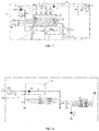
- FIG. 7 is a circuit diagram of the light string control unit of the light string in FIG. 6 ;
- FIG. 8 is a circuit diagram of the light strip control unit of each LED bulb of the light string.
- FIG. 9 is a waveform diagram of the output driving signal of the light string control unit.
- the LED flame bulb of the present embodiment includes a bulb shell 11 , a base 12 , an LED light strip 13 , and a light strip control unit.
- the base 12 is covered on the open end of the bulb shell, the LED light strip 13 is arranged in the bulb shell 11 with one end hung on the base 12 .
- the light strip control unit is arranged on the base 12 and electrically connected to the light strip 13 .
- the bulb shell 11 is a cylindrical, gallbladder, multi-prism, multi-prism crystal, sphere, ellipsoid, water drop body, flame body and other shapes with an open end.
- the base 12 can refer to relevant standards to choose a G-type or E-type screw holder.
- the G-type screw holder is a bulb holder that is connected to the positive and negative poles of the power supply with a double pin or a plug.
- the E-type screw holder is a bulb holder with screw thread arranged in the side wall of the cylinder and a bottom contact insulated from the screw thread arranged at the bottom, which are used to connect to the positive and negative poles of the power supply.
- the LED light strip 13 includes a substrate and a plurality of LED beads disposed on the substrate.
- the substrate is divided into a flame bottom area A, a flame core area B, and an outer flame area C in sequence from the end of the substrate connected to the base to the other end.
- the LED beads in each area flash in accordance with preset flashing methods.
- the LED beads in the flame bottom area A and the outer flame area C are switched on and off according to the set frequency respectively. In some embodiments, methods to switch on and off of the LED beads in the flame bottom area A and the outer flame area C are synchronized.
- At least two LED beads are arranged in the flame core area B, and the LED beads of area B in the linear direction from the flame bottom area A to the flame area C are switched on and off in sequence, wherein there is only one LED bead lit at the same moment.
- the flame bottom area A, the flame core area B and the outer flame area C are with different brightness respectively, wherein the flame core area B has the highest brightness.
- This effect is achieved by setting the LED beads in different areas to have different power, or by controlling the light strip control unit to supply different current to the LED beads in different areas.
- the bulb differentiates the brightness of different areas to imitate different flame brightness of different parts.
- the substrate is a PCB board, and a total of 7 LED beads L 1 ⁇ L 7 are linearly arranged on the substrate at equal intervals.
- the flame bottom area includes LED bead L 1
- the flame core area includes LED beads L 2 -L 6
- the outer flame area includes LED bead L 7
- the rated power ratio of the LED beads set in the flame bottom area, the flame core area and the outer flame area is 1:(3 ⁇ 5):(2 ⁇ 3), in order to simulate different brightness of different flame areas.
- the light strip control unit 14 includes a voltage level output module IN 1 , a voltage regulating unit 141 and an LED driving unit, all of which are electrically connected in sequence.
- a stable voltage level is provided to the LED driving unit from the voltage level output module IN 1 after being stabilized by the voltage regulating unit 141 .
- the input terminal of the voltage level output module IN 1 is connected to the positive pole of the base, the output terminal pin 1 of the voltage level output module IN 1 is grounded, and its output terminal pin 2 outputs a voltage level signal;
- the voltage regulating unit 141 includes a diode D 1 and a resistor R 1 connected in series.
- the LED driving unit is a chip U 1 .
- the chip U 1 includes a VDD pin to receive DC power supply, a grounded VSS pin, and six pins of IOB 0 -IOB 5 to input or output signals.
- the VDD pin of the chip U 1 is grounded through a capacitor C 1 to filter clutter signals.
- the IOB 4 pin and the IOB 5 pin of the chip U 1 are used to receive signals for mode selection, the IOB 5 pin is connected to pin 2 of the output terminal of the voltage level output module IN 1 , and when it receives the signal, the chip U 1 drives the LED beads to flash to simulate the flame.
- the IOB 4 pin can be connected to an external circuit, where other mode of driving LED bead flashing can be set in the chip U 1 . When the IOB 4 pin receives an input signal, the chip U 1 can light up LED beads in other preset mode.
- LED bead L 2 and L 3 are connected in an anti-parallel method and then connected in series between the IOB 0 pin and the IOB 1 pin of the chip U 1 .
- LED bead L 4 and L 5 are connected in an anti-parallel method and then connected in series between the IOB 0 pin and the IOB 2 pin of the chip U 1 .
- LED bead L 6 and L 7 are connected in anti-parallel method and then connected in series between the IOB 1 pin and the IOB 2 pin of the chip U 1 .
- the IOB 3 pin of the chip U 1 is connected to LED bead L 1 in series and then grounded.
- the chip U 1 controls on and off of each LED bead through the square wave signal output from the pins of IOB 0 -IOB 3 .
- This connecting method can reduce output ends of the light strip control unit accordingly and improve the utilization rate of the output ends of the light strip control unit.
- the chip U 1 controls flashing modes of LED beads L 1 -L 7 according to the preset control program.
- the chip U 1 controls the first bead L 1 and the end LED bead L 7 in the linear LED beads on and off synchronously, and the middle LED beads L 2 -L 6 on and off in sequence, to emulate flame flickering.
- LED beads L 2 -L 6 are lit successively, only one LED bead is lit at the same moment.
- a digital-to-analog conversion module DAC is also provided in the chip U 1 to convert the square wave signal generated by the chip U 1 into an analog signal, and output the analog current with varying amplitude through the pins of IOB 0 -IOB 3 .
- the driving current amplitude of the flame bottom area A and the outer flame area C when lighting from the pins of IOB 0 -IOB 3 is less than that of the LED beads in the flame core area B.
- the brightness of the LED beads in each area is changed to simulate the different brightness of each part of a flame when flame flickering.
- the amplitude of the current to the LED beads in the same area can also vary with time to emulate the changing effect when the flame beats with time.
- each output current of the chip U 1 is a sine wave. Referring to FIG. 4 , the different shades of the squares in the figure indicate that the current amplitude received by the LED beads are in different amplitude ranges.
- the flashing mode of LED bead L 1 of the LED beads in the flame bottom area is lit once at intervals of one frame.
- the brightness of the LED bead L 1 increases as the current amplitude increases when it is lit.
- the brightness of the LED bead L 1 decreases as the current amplitude decreases when it is lit.
- the flashing method of LED bead L 7 in the outer flame area C is similar to that in the flame bottom area A, except that the lowest and highest current amplitude of the LED bead L 7 are both higher than that in the flame bottom area A.
- the LED bead L 2 in the flame core area B is lit in frame 1 with a current amplitude higher than that in the other two areas, and then LED bead L 3 -L 6 is lit in turn in frames from 2 to 5 with a current of the same amplitude as that of LED bead L 2 in frame 1 to complete a cycle.
- the cycle is repeated in frames 6 to 10 and then in frames 11 to 15 , with the current amplitude in each cycle increased.
- the brightness change of the linearly arranged LED beads are shown by the higher brightness of the central area and the lower brightness of the two ends, which simulate flame brightness changing with time.
- a plurality of LED beads are arranged linearly on both sides of the substrate of the LED light strip, and the LED beads on the same position of both sides have the same flashing mode.
- the number of LED beads on the light strip is variable as long as the proportion of the flame core area is greater than that of other areas, such as 1:2:1 or 2:3:2 or other, in order to simulate the different forms of flame bottom, flame core and the outer flame.
- the ratio of the actual luminous power of the LED beads in the flame bottom area A, flame core area B, and the outer flame area C can be 1:2:1 or 1:3:2 or other, to realize different brightness of different parts of the flame.
- multiple groups of LED beads may be arranged linearly along the direction of the light strip on the same surface of the substrate. Defining the direction from the flame bottom area to the outer flame area is radial and the direction perpendicular to the radial on the substrate is lateral, the LED beads simulate the flickering flame in a method that the LED beads in the lateral rows of the flame bottom area and the outer flame area keep flashing, and the LED beads in the lateral rows of the flame core area flash in sequence.
- the LED bulb in embodiments above can mimic flame effect of beating and flickering, and has the characteristics of small size, easy transport and carry, simple components, high integration and low cost, which has a wide application prospect.
- the substrate of the LED bulb is divided into the flame bottom area, the flame core area, and the outer flame area, and arranged with the LED beads in the flame bottom area and the outer flame area keeping flashed while LED beads in the flame core area lighting up in sequence to simulate flame flicker. Further, by setting different rated power of the LED beads or supplying different current to the LED beads in above different areas, a vivid effect of different brightness of flame bottom, flame core and the outer flame areas is achieved. Furthermore, in the embodiment of making the brightness of each area different by changing the supplying current, the current provided to each LED bead can also be changed with time, to realize the effect of flame brightness changing with time.
- a light string includes a light string control unit 21 , a connecting portion 22 , and a plurality of LED flame bulbs 10 .
- the plurality of LED flame bulbs are connected in parallel to the connecting portion 22 , and the light string control unit 21 receives driving signal and controls each LED flame bulb 10 on and off through the connecting portion 22 .
- the connecting portion 22 includes a positive wire and a negative wire, one end of the positive wire is connected to the output end of the light string control unit 21 and the positive wire is also connected to the positive pole of the base of each LED flame bulb.
- One end of the negative wire is connected to the negative pole of the DC power and the negative wire is also connected to the negative pole of the base of each LED flame bulb.
- the light string control unit 21 includes a signal generator 211 , a power conversion unit 212 , an oscillator Y 1 , an infrared signal receiving unit 213 , a key signal input unit 214 , and a driving signal conversion unit 215 .
- the signal generator 211 is a chip U 2 , which includes a VDD pin for receiving driving power, a VSS pin for grounding, an OSCI pin for receiving oscillator input, an OSCO pin for receiving oscillator output, an IR pin for receiving the infrared control signal output from the infrared signal receiving unit, a KEY pin for receiving the KEY control output from the key signal input unit, and an OUT pin for outputting the signal.
- the VDD pin of the chip U 2 is grounded through the capacitor C 4
- the OSCI pin is grounded through the capacitor C 5
- the OSCO pin is grounded through the capacitor C 6 , which are used to filter out clutter signals.
- a variety of programs are preset in the chip U 2 to control the lighting mode of each LED bulb, which can control the LED bulbs to work in constant lighting mode at the same time or in sequence, or work in flame flicker emulation mode at the same time or in sequence.
- the power conversion unit 212 includes a diode D 2 and a resistor R 2 connected in series, wherein the positive terminal of the diode D 2 is connected to the DC power, and the negative terminal of the diode D 2 is connected to the VDD pin of the chip U 2 through the resistor R 2 .
- the infrared signal receiving unit 213 includes an infrared signal receiving unit, a resistor R 4 and a capacitor C 7 .
- the infrared signal receiving unit includes three pins, the first pin of the infrared signal receiving unit is connected to the DC power through a resistor R 4 , and is also connected to the ground wire of the second pin through a capacitor C 7 at the same time; the second pin of the infrared signal receiving unit is grounded; and the third pin of the infrared signal receiving unit is connected to the IR pin of the chip U 2 .
- the key signal input unit 214 includes a switch Si, of which one end is grounded and the other end is connected to the KEY pin of the chip U 2 .
- the light string control unit may receive the control signal input by the user from the infrared remote control or the switch, and then control the lighting mode of each LED bulb on the light string.
- the driving signal conversion unit 215 includes a MOS transistor Q 1 , a resistor R 3 , a resistor R 5 and a resistor R 6 , a capacitor C 2 , a capacitor C 3 and a capacitor C 8 , a diode D 3 , a 3 V voltage conversion module F, and a signal output module OUT 1 .
- the voltage from the DC power VIN is stabilized at 3V through the 3.0V voltage conversion module F, then the voltage from the DC power VIN is connected to the signal output module OUT 1 through the diode D 3 .
- the DC power VIN is also grounded through the capacitor C 8 .
- One end of the capacitor C 2 with high capacitance and one end of the capacitor C 3 with low capacitance are connected between the 3.0V voltage conversion module F and the diode D 3 , and the other ends are grounded to filter the power signal.
- One end of the resistor R 6 is connected between the diode D 3 and the signal output module OUT 1 , and the other end is grounded.
- the MOS transistor Q 1 is a P-channel enhanced MOS transistor, its source is connected to the DC power VIN, its gate is connected to the DC power VIN through a resistor R 5 , which is also connected to pin 5 of the chip U 2 through a resistor R 3 , and its drain is connected between the diode D 3 and the signal output module OUT 1 .
- the signal output module OUT 1 includes two input pins and one output pin, wherein the input pin 1 is electrically connected to the diode D 3 , the input pin 2 is grounded, and the output pin is connected to the positive wire of the connecting portion 22 .
- the user may press the switch Si or use the infrared remote control to transmit a signal to the infrared receiving unit to input the control signal.
- the VDD pin of the chip U 2 receives the driving voltage regulated by the power conversion unit and starts to work, and the oscillator Y 1 outputs a 32768 Hz clock oscillation signal to start-up the chip U 2 .
- the chip U 2 changes the flashing mode of the light string once according to the control signal input by the user each time, and the chip U 2 outputs varying signal to control the drain of the PMOS (positive channel Metal Oxide Semiconductor) transistor disconnected or output negative current, forming a 32 BIT drive signal that carries the control information of all LED bulbs and is output by the output module OUT 1 .
- the driving signal is transmitted through the connecting portion to the light strip control unit of each LED flame bulb to realize its specific lighting mode.
- the light string control unit will output DC power to the light strip control unit of each LED bulb.
- the light string control unit when the user inputs an infrared signal to the infrared receiving unit or presses the key switch, which controls each LED bulb to work in constant lighting mode, the light string control unit will control each LED bulb on the light string to light up constantly at the same time. Depending on the user's input of infrared control signals or the user's presses of the switch, the light string control unit can control the lighting mode of each LED bulb of the light string to switch to constant lighting sequentially, flame flicker emulation simultaneously or flame flicker emulation sequentially.
- the circuit structure of the light strip control unit of the LED bulb shall be adjusted in order to cooperate with the control unit of the light string.
- FIG. 8 is a circuit diagram of the light strip control unit 14 ′ applied to the LED bulb in the light string.
- the structure of the current conversion unit and the LED driving unit is consistent with the structure of the above embodiments.
- the difference is that a signal receiving unit is also connected between the positive pole of diode D 1 in the current conversion unit and the VDD pin of the LED driving unit.
- the signal receiving unit is a chip U 3 , which is used to receive the signal of the light string control unit.
- the chip U 3 includes a VDD pin for receiving DC power supply, a CK pin for receiving a clock signal, a VSS pin for grounding, and pins of OUT 1 and OUT 2 for outputting signals.
- the CK pin of the chip U 3 is connected to the output pin 2 of the drive voltage level output module IN 1 through the pull-up resistor R 7 , and is also grounded through the resistor R 8 to achieve voltage clamping;
- the OUT 1 pin of the chip U 3 is connected to the IOB 5 pin of the chip U 1 ;
- the OUT 2 pin of the chip U 3 is connected to the IOB 4 pin of the chip U 1 ;
- the VDD pin of the chip U 3 is also grounded through capacitor C 9 to filter clutter signals.
- the chip U 1 is preset with two LED bead driving modes of constant lighting and flame flicker emulation, of which the constant lighting mode is triggered when the IOB 4 pin of chip U 1 receives a signal, and the flame flicker emulation mode is triggered when the IOB 5 pin of chip U 1 receives a signal.
- the light string control unit 14 ′ works, referring to FIG. 9 , each time the user inputs a control signal, the light string control unit will output a driving signal, and the driving signal is received by the CK pin of the chip U 3 of the signal receiving unit of each LED bulb.
- the CK pin of the chip U 3 receives the falling edge of the square wave of the driving signal, the chip U 3 begins to read the 32 bit data input after the falling edge of the square wave, so as to confirm whether the LED bulb works, and whether the working mode is constant lighting mode or flame flicker emulation mode.
- the chip U 3 controls the IOB 0 -IOB 3 pins of the chips U 1 not to output the voltage level by output signals from pins OUT 1 and OUT 2 of the chip U 3 , therefore the LED beads are not lit.
- the data transmission process is separated from the LED beads driving process to different time to avoid signal interference.
- the chip U 3 receives the falling edge of the square wave of the driving signal again, the chip U 3 stops reading the square wave signal, but outputs the control signal to the chip U 1 depending on the previously read signal to control its working mode. Meanwhile, the chip U 1 receives the driving voltage level to start driving the LED bead. The chip U 1 keeps driving the LED beads until the chip U 3 detects the next falling edge signal of the square wave and repeats above process of reading the driving signal.
- the OUT 2 pin of the chip U 3 When the CK pin of the chip U 3 receives the driving signal that drives the LED bulb to illuminate constantly, the OUT 2 pin of the chip U 3 outputs a signal to the IOB 4 pin of the chip U 1 , and the chip U 1 works in the constant lighting mode.
- the IOB 0 -IOB 3 pins of the chip U 1 output multiple driving voltage levels to light up each LED bead constantly.
- the OUT 1 pin of the chip U 3 outputs the signal to the IOB 5 pin of the chip U 1 , and the chip U 1 works in flame flicker emulation mode.
- the IOB 0 -IOB 3 pins of the chip U 1 output signals according to a preset program, so that the LED beads in the flame bottom area and the outer flame area on the light strip keep flashing, and the LED beads in the flame core area light up in sequence to simulate flame flickering.
- the LED light string provided by the present application has a variety of lighting modes including constant lighting, sequential flashing, synchronous flame flickering and sequential flame flickering, which can be realized by infrared remote control or switch control, simple to operate and rich in modes.
- the light string control unit u controls a plurality of LED bulbs in parallel through the positive wire and the negative wire, which can control the on/off operation of each LED bulb separately. Compared with the prior art where a multi-wire connection structure is required for the control unit and each LED bulb, only the positive wire and negative wire are needed due to the simplified connection between the light string control unit and each LED bulb.
- the power conversion unit when the input power supply is AC power less than or equal to 230V, the power conversion unit includes a rectifier circuit and a voltage regulator circuit connected in sequence.
Landscapes
- Engineering & Computer Science (AREA)
- General Engineering & Computer Science (AREA)
- Computer Networks & Wireless Communication (AREA)
- Microelectronics & Electronic Packaging (AREA)
- Circuit Arrangement For Electric Light Sources In General (AREA)
- Non-Portable Lighting Devices Or Systems Thereof (AREA)
Abstract
Description
Claims (5)
Applications Claiming Priority (3)
| Application Number | Priority Date | Filing Date | Title |
|---|---|---|---|
| CN201910646338.7 | 2019-07-17 | ||
| CN201910646338.7A CN110332496A (en) | 2019-07-17 | 2019-07-17 | Flame flickering LED lights and string lights |
| PCT/CN2019/099543 WO2021007892A1 (en) | 2019-07-17 | 2019-08-07 | Flame flashing led lamp and lamp string |
Publications (2)
| Publication Number | Publication Date |
|---|---|
| US20210254803A1 US20210254803A1 (en) | 2021-08-19 |
| US11204144B2 true US11204144B2 (en) | 2021-12-21 |
Family
ID=68145776
Family Applications (1)
| Application Number | Title | Priority Date | Filing Date |
|---|---|---|---|
| US15/733,534 Active US11204144B2 (en) | 2019-07-17 | 2019-08-07 | LED flame bulb and light string containing same |
Country Status (3)
| Country | Link |
|---|---|
| US (1) | US11204144B2 (en) |
| CN (1) | CN110332496A (en) |
| WO (1) | WO2021007892A1 (en) |
Families Citing this family (4)
| Publication number | Priority date | Publication date | Assignee | Title |
|---|---|---|---|---|
| CN216203043U (en) * | 2021-09-27 | 2022-04-05 | 珈伟新能源股份有限公司 | Linearly distributed flying firefly lamp |
| CN113915579A (en) * | 2021-09-28 | 2022-01-11 | 海宁市鑫诚电子有限公司 | LED lamp bead capable of simulating flame |
| CN218295376U (en) * | 2022-10-17 | 2023-01-13 | 江苏智慧光彩光电科技有限公司 | Lighting lamp |
| CN115460732B (en) * | 2022-11-11 | 2023-03-24 | 深圳市爱图仕影像器材有限公司 | Light equipment control method and device, terminal equipment and storage medium |
Citations (19)
| Publication number | Priority date | Publication date | Assignee | Title |
|---|---|---|---|---|
| US20050196716A1 (en) * | 2004-03-03 | 2005-09-08 | Haab Dan B. | Artificial flame |
| US20060208666A1 (en) * | 2005-03-16 | 2006-09-21 | Johnson David C | Electronic lighting device for simulating a flame |
| CA2577486A1 (en) | 2007-02-07 | 2008-08-07 | Excellence Opto. Inc. | Led melody decoration kit with multicolor light sources |
| US20120049765A1 (en) * | 2010-08-31 | 2012-03-01 | Sun Lu | Chandelier lamp system |
| CN103561507A (en) | 2013-09-30 | 2014-02-05 | 常州市巨泰电子有限公司 | LED lamp string single way band control circuit and control method |
| CN204157098U (en) | 2014-06-23 | 2015-02-11 | 何业龙 | A kind of multi-mode LED cascade control circuit and LED string |
| US20150369432A1 (en) * | 2014-06-24 | 2015-12-24 | Xiaofeng Li | Electric candle with illuminating panel |
| CN206130878U (en) | 2016-09-23 | 2017-04-26 | 福建万象春电子科技有限公司 | LED flame lamp |
| CN106764915A (en) | 2016-12-02 | 2017-05-31 | 广州漫美帝灯光设备有限公司 | The three-dimensional flame lamp of emulation and its control method |
| CN108076565A (en) | 2017-12-28 | 2018-05-25 | 鸿利智汇集团股份有限公司 | A kind of dimmable LED device and control method |
| US20180163937A1 (en) * | 2015-01-08 | 2018-06-14 | Atake Digital Technology (Shenzhen) Co., Ltd. | Electronic candle lamp and light-emitting diode (led) lamp |
| US10028353B2 (en) | 2015-08-29 | 2018-07-17 | Taizhou Heystar Electronic Technology Co., Ltd | LED lamp string having selectable light emitting mode |
| CN207740994U (en) | 2018-01-29 | 2018-08-17 | 欧创实业(深圳)有限公司 | Multifunction electronic flame lamp |
| CN208475210U (en) | 2018-07-20 | 2019-02-05 | 常州市环科电子有限公司 | Solar energy flame lamp |
| CN109519860A (en) | 2018-12-12 | 2019-03-26 | 海宁市鑫诚电子有限公司 | A kind of LED luminous flame component |
| CN109882794A (en) | 2019-02-22 | 2019-06-14 | 浙江生辉照明有限公司 | Flame lamp control device and flame lamp |
| US10344930B1 (en) | 2018-04-30 | 2019-07-09 | Feit Electric Company, Inc. | Flame lamp |
| CN209386191U (en) | 2018-12-12 | 2019-09-13 | 海宁市鑫诚电子有限公司 | A kind of LED luminous flame component |
| CN209540754U (en) | 2019-02-22 | 2019-10-25 | 浙江生辉照明有限公司 | Flame lamp control device and flame lamp |
-
2019
- 2019-07-17 CN CN201910646338.7A patent/CN110332496A/en active Pending
- 2019-08-07 WO PCT/CN2019/099543 patent/WO2021007892A1/en not_active Ceased
- 2019-08-07 US US15/733,534 patent/US11204144B2/en active Active
Patent Citations (21)
| Publication number | Priority date | Publication date | Assignee | Title |
|---|---|---|---|---|
| US20050196716A1 (en) * | 2004-03-03 | 2005-09-08 | Haab Dan B. | Artificial flame |
| US20060208666A1 (en) * | 2005-03-16 | 2006-09-21 | Johnson David C | Electronic lighting device for simulating a flame |
| CA2577486A1 (en) | 2007-02-07 | 2008-08-07 | Excellence Opto. Inc. | Led melody decoration kit with multicolor light sources |
| US20120049765A1 (en) * | 2010-08-31 | 2012-03-01 | Sun Lu | Chandelier lamp system |
| CN103561507A (en) | 2013-09-30 | 2014-02-05 | 常州市巨泰电子有限公司 | LED lamp string single way band control circuit and control method |
| CN204157098U (en) | 2014-06-23 | 2015-02-11 | 何业龙 | A kind of multi-mode LED cascade control circuit and LED string |
| US20150369432A1 (en) * | 2014-06-24 | 2015-12-24 | Xiaofeng Li | Electric candle with illuminating panel |
| US20180163937A1 (en) * | 2015-01-08 | 2018-06-14 | Atake Digital Technology (Shenzhen) Co., Ltd. | Electronic candle lamp and light-emitting diode (led) lamp |
| US10028353B2 (en) | 2015-08-29 | 2018-07-17 | Taizhou Heystar Electronic Technology Co., Ltd | LED lamp string having selectable light emitting mode |
| CN206130878U (en) | 2016-09-23 | 2017-04-26 | 福建万象春电子科技有限公司 | LED flame lamp |
| CN106764915A (en) | 2016-12-02 | 2017-05-31 | 广州漫美帝灯光设备有限公司 | The three-dimensional flame lamp of emulation and its control method |
| CN108076565A (en) | 2017-12-28 | 2018-05-25 | 鸿利智汇集团股份有限公司 | A kind of dimmable LED device and control method |
| CN207740994U (en) | 2018-01-29 | 2018-08-17 | 欧创实业(深圳)有限公司 | Multifunction electronic flame lamp |
| US10422495B1 (en) | 2018-04-30 | 2019-09-24 | Feit Electric Company, Inc. | Flame lamp |
| US20190360651A1 (en) | 2018-04-30 | 2019-11-28 | Feit Electric Company, Inc. | Flame lamp |
| US10344930B1 (en) | 2018-04-30 | 2019-07-09 | Feit Electric Company, Inc. | Flame lamp |
| CN208475210U (en) | 2018-07-20 | 2019-02-05 | 常州市环科电子有限公司 | Solar energy flame lamp |
| CN109519860A (en) | 2018-12-12 | 2019-03-26 | 海宁市鑫诚电子有限公司 | A kind of LED luminous flame component |
| CN209386191U (en) | 2018-12-12 | 2019-09-13 | 海宁市鑫诚电子有限公司 | A kind of LED luminous flame component |
| CN209540754U (en) | 2019-02-22 | 2019-10-25 | 浙江生辉照明有限公司 | Flame lamp control device and flame lamp |
| CN109882794A (en) | 2019-02-22 | 2019-06-14 | 浙江生辉照明有限公司 | Flame lamp control device and flame lamp |
Non-Patent Citations (1)
| Title |
|---|
| International Search Report dated Apr. 20, 2020 from PCT Application No. PCT/CN2019/099543. |
Also Published As
| Publication number | Publication date |
|---|---|
| CN110332496A (en) | 2019-10-15 |
| WO2021007892A1 (en) | 2021-01-21 |
| US20210254803A1 (en) | 2021-08-19 |
Similar Documents
| Publication | Publication Date | Title |
|---|---|---|
| US11204144B2 (en) | LED flame bulb and light string containing same | |
| US4510556A (en) | Electronic lighting apparatus for simulating a flame | |
| US6926423B2 (en) | Light with simulated candle flicker | |
| US6066924A (en) | Candle emulation | |
| US10184627B2 (en) | LED lamp convenient to switch flame direction | |
| CN202043348U (en) | Light-emitting diode (LED) lamp capable of conveniently regulating color temperature | |
| US8820984B2 (en) | Programmable lighting effect device and system | |
| CN101491159A (en) | Device and method for addressing power to a load selected from a plurality of loads | |
| CN101737700B (en) | Color-changing light with acoustic control music color lamps | |
| CN106764915A (en) | The three-dimensional flame lamp of emulation and its control method | |
| CN104315453B (en) | High flame lamp true to nature and its implementation | |
| CN109769332A (en) | An indication method, indicator circuit and electronic product | |
| CN105992445B (en) | A kind of sound effect control system | |
| US8188669B2 (en) | Decorative lamp for displaying snowing or water-flowing pattern | |
| CN201344416Y (en) | Peacock spreading tail decorative wall lamp | |
| US7108397B2 (en) | String lamps device | |
| CN205001932U (en) | Can select LED lights cluster of luminous mode | |
| CN213342755U (en) | Eye moistening lamp capable of simulating natural light | |
| US10609775B1 (en) | Three-line four-way light string and control system thereof | |
| CN206118124U (en) | But low pressure is remote control light modulation lamp cluster regularly | |
| CN204026504U (en) | Many wicks wave electric candle | |
| CN204580836U (en) | A kind of electronic incense burner of USB port charging | |
| CN203131690U (en) | Smokeless simulation candle | |
| JP3214075U (en) | Dimmable lamp that can be controlled by ordinary switches | |
| CN216253300U (en) | Colorful light analog control circuit and light source equipment |
Legal Events
| Date | Code | Title | Description |
|---|---|---|---|
| AS | Assignment |
Owner name: JIANGMEN LIDU LIGHTING CO., LTD., CHINA Free format text: ASSIGNMENT OF ASSIGNORS INTEREST;ASSIGNORS:XU, GUODU;LU, SHAOMING;REEL/FRAME:053561/0637 Effective date: 20200730 |
|
| FEPP | Fee payment procedure |
Free format text: ENTITY STATUS SET TO UNDISCOUNTED (ORIGINAL EVENT CODE: BIG.); ENTITY STATUS OF PATENT OWNER: SMALL ENTITY |
|
| FEPP | Fee payment procedure |
Free format text: ENTITY STATUS SET TO SMALL (ORIGINAL EVENT CODE: SMAL); ENTITY STATUS OF PATENT OWNER: SMALL ENTITY |
|
| STPP | Information on status: patent application and granting procedure in general |
Free format text: NON FINAL ACTION MAILED |
|
| STPP | Information on status: patent application and granting procedure in general |
Free format text: RESPONSE TO NON-FINAL OFFICE ACTION ENTERED AND FORWARDED TO EXAMINER |
|
| STPP | Information on status: patent application and granting procedure in general |
Free format text: NOTICE OF ALLOWANCE MAILED -- APPLICATION RECEIVED IN OFFICE OF PUBLICATIONS |
|
| STPP | Information on status: patent application and granting procedure in general |
Free format text: PUBLICATIONS -- ISSUE FEE PAYMENT VERIFIED |
|
| STCF | Information on status: patent grant |
Free format text: PATENTED CASE |
|
| MAFP | Maintenance fee payment |
Free format text: PAYMENT OF MAINTENANCE FEE, 4TH YR, SMALL ENTITY (ORIGINAL EVENT CODE: M2551); ENTITY STATUS OF PATENT OWNER: SMALL ENTITY Year of fee payment: 4 |