US11198024B2 - Controlled descent safety systems and methods - Google Patents
Controlled descent safety systems and methods Download PDFInfo
- Publication number
- US11198024B2 US11198024B2 US16/258,103 US201916258103A US11198024B2 US 11198024 B2 US11198024 B2 US 11198024B2 US 201916258103 A US201916258103 A US 201916258103A US 11198024 B2 US11198024 B2 US 11198024B2
- Authority
- US
- United States
- Prior art keywords
- throttle
- capstan
- chassis
- tension member
- flexible tension
- Prior art date
- Legal status (The legal status is an assumption and is not a legal conclusion. Google has not performed a legal analysis and makes no representation as to the accuracy of the status listed.)
- Active, expires
Links
Images


Classifications
-
- A—HUMAN NECESSITIES
- A62—LIFE-SAVING; FIRE-FIGHTING
- A62B—DEVICES, APPARATUS OR METHODS FOR LIFE-SAVING
- A62B1/00—Devices for lowering persons from buildings or the like
- A62B1/06—Devices for lowering persons from buildings or the like by making use of rope-lowering devices
- A62B1/14—Devices for lowering persons from buildings or the like by making use of rope-lowering devices with brakes sliding on the rope
-
- A—HUMAN NECESSITIES
- A62—LIFE-SAVING; FIRE-FIGHTING
- A62B—DEVICES, APPARATUS OR METHODS FOR LIFE-SAVING
- A62B1/00—Devices for lowering persons from buildings or the like
- A62B1/06—Devices for lowering persons from buildings or the like by making use of rope-lowering devices
- A62B1/08—Devices for lowering persons from buildings or the like by making use of rope-lowering devices with brake mechanisms for the winches or pulleys
- A62B1/10—Devices for lowering persons from buildings or the like by making use of rope-lowering devices with brake mechanisms for the winches or pulleys mechanically operated
-
- B—PERFORMING OPERATIONS; TRANSPORTING
- B66—HOISTING; LIFTING; HAULING
- B66D—CAPSTANS; WINCHES; TACKLES, e.g. PULLEY BLOCKS; HOISTS
- B66D1/00—Rope, cable, or chain winding mechanisms; Capstans
- B66D1/28—Other constructional details
- B66D1/40—Control devices
- B66D1/42—Control devices non-automatic
-
- B—PERFORMING OPERATIONS; TRANSPORTING
- B66—HOISTING; LIFTING; HAULING
- B66D—CAPSTANS; WINCHES; TACKLES, e.g. PULLEY BLOCKS; HOISTS
- B66D1/00—Rope, cable, or chain winding mechanisms; Capstans
- B66D1/60—Rope, cable, or chain winding mechanisms; Capstans adapted for special purposes
- B66D1/74—Capstans
- B66D1/7442—Capstans having a horizontal rotation axis
- B66D1/7452—Capstans having a horizontal rotation axis driven manually only
-
- B—PERFORMING OPERATIONS; TRANSPORTING
- B66—HOISTING; LIFTING; HAULING
- B66D—CAPSTANS; WINCHES; TACKLES, e.g. PULLEY BLOCKS; HOISTS
- B66D5/00—Braking or detent devices characterised by application to lifting or hoisting gear, e.g. for controlling the lowering of loads
- B66D5/02—Crane, lift hoist, or winch brakes operating on drums, barrels, or ropes
- B66D5/16—Crane, lift hoist, or winch brakes operating on drums, barrels, or ropes for action on ropes or cables
-
- B—PERFORMING OPERATIONS; TRANSPORTING
- B66—HOISTING; LIFTING; HAULING
- B66D—CAPSTANS; WINCHES; TACKLES, e.g. PULLEY BLOCKS; HOISTS
- B66D5/00—Braking or detent devices characterised by application to lifting or hoisting gear, e.g. for controlling the lowering of loads
- B66D5/02—Crane, lift hoist, or winch brakes operating on drums, barrels, or ropes
- B66D5/18—Crane, lift hoist, or winch brakes operating on drums, barrels, or ropes for generating braking forces which are proportional to the loads suspended; Load-actuated brakes
-
- B—PERFORMING OPERATIONS; TRANSPORTING
- B66—HOISTING; LIFTING; HAULING
- B66D—CAPSTANS; WINCHES; TACKLES, e.g. PULLEY BLOCKS; HOISTS
- B66D2700/00—Capstans, winches or hoists
- B66D2700/01—Winches, capstans or pivots
- B66D2700/0108—Winches, capstans or pivots with devices for paying out or automatically tightening the cable
Definitions
- Embodiments of the technology relate, in general, to controlled velocity devices, and in particular to personal controlled descent control devices.
- FIG. 1 is a perspective view of a controlled descent device according to one embodiment.
- FIG. 2 is an exploded perspective view of a controlled descent device according to one embodiment.
- FIG. 3 is side elevation view of a capstan according to one embodiment of a controlled descent device according to a first mode of operation.
- FIG. 4 is a schematic representation of a controlled descent device according to a first mode of operation.
- FIG. 5 is a schematic representation of a controlled descent device according to a second mode of operation.
- FIG. 6 is an exploded perspective view of a controlled descent device according to one embodiment.
- FIG. 7 is a cut-away side elevation view of a controlled descent device according to one embodiment.
- FIG. 8 is an enlarged cross-sectional view of the cut-away side elevation view of a controlled descent device shown in FIG. 7 .
- FIG. 9 is a cut-away side elevation view of a controlled descent device showing the operation of a controlled descent device according to one embodiment.
- FIG. 10 is a perspective view of a throttle of the present disclosure.
- FIG. 11 is a perspective view of a throttle of the present disclosure.
- FIG. 12 is a perspective view of a throttle of the present disclosure.
- FIG. 13 is a side elevation view of a throttle of the present disclosure.
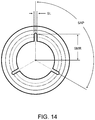
- FIG. 14 is a front elevation view of a throttle of the present disclosure.
- FIG. 15 is a graph showing certain data related to the operation of a controlled descent device of the present disclosure.
- FIG. 16 is a perspective view of a throttle of the present disclosure.
- the device disclosed herein is useful as a load lowering velocity controller.
- the device can operate broadly as a velocity control mechanism for any load experiencing a force tending to move or accelerate it.
- the device disclosed herein can be used to control the velocity of an ascending load, for example, an ascending weather balloon.
- the device disclosed herein can be used to control the relative velocity of a laterally moving vehicle, for example, a trailer that has come loose from a towing vehicle.
- the device will be disclosed in detail herein as a load lowering velocity controller of the type useful in lowering people out of buildings in emergency situations.
- Controlled descent from emergency situations may be accomplished by a skilled practitioner, such as a firefighter, trained in rappelling. To an untrained, young or infirm individual, exiting an emergency situation with a mere rope can be extremely dangerous. Additionally, even trained responders, such as firefighters, may find themselves in situations where they are injured, carrying additional weight such as while rescuing others, or lack the equipment necessary for a controlled descent. Further, the practitioner may require use of his or her hands during the descent to operate equipment such as a firearm or manipulate themselves or another payload.
- the controlled descent device disclosed herein can be utilized in a hands-free operation by trained and untrained persons alike.
- Embodiments described herein can be less expensive, have less mass, be less bulky, and can be easier to maintain than powered winches or other existing safety systems. Embodiments described herein may be useful in power outages, such as those frequently occurring during fires or disasters, where an external power source may not be required. Embodiments described herein can be operated automatically, without hand braking, in a compact and cost-effective manner. Embodiments of the system can be used for a variety of different weights of users without the need to adjust for different weights. For example, a firefighter within an average weight range could attach a device described herein and use the device to safely descend from a building without being required to manipulate the device based on his or her weight or otherwise tailor the system during descent.
- a device described herein can be designed based on other factors related to weight, such as the waist size or the clothing sizes of a user.
- controlled descent devices can be designed and manufactured for predetermined load ranges, including weight ranges for persons such as firefighters.
- multiple technologies can be incorporated into a single descent control unit that can be suitably fabricated as a portable and/or wearable system.
- the system in one embodiment, as discussed below with respect to the system shown FIG. 4 , can allow a user, after confirmation of device operation within the desired controlled velocity range, to simply clip or otherwise attach the device to himself, attach a free end of the flexible tension member, such as a rope, onto a relatively fixed position and jump to a place of safety while descending at a range of predetermined rates.
- the controlled descent device can be permanently mounted in strategic locations, as discussed below with respect to the system shown in FIG. 5 .
- a device can be ready for use by a user, after confirmation of device operation within the desired controlled velocity range, who clips himself onto a free end of the flexible tension member associated with the device.
- the device disclosed herein can utilize moving parts to adjust the velocity control profile, prior to or during use.
- Moving parts can be used to manipulate the gain of the capstan 28 or the force generated by the throttle 30 .
- Parts can be moved by way of user input, or by mechanisms powered from the kinetic energy of the payload, or actuated by forces present in the device, such as tensile force in the flexible tension member.
- the device disclosed here in can be used by a person, after confirmation of device operation within the desired controlled velocity range, without the person interacting with the device in any way to effect controlled descent. That is, the device can be operable for use in lowering a load, such as a person, in a controlled manner with the person not needing to manipulate the device for it to work properly.
- controlled descent includes translation of an object within a controlled velocity range, including constant velocity descent of a load under the force of gravity.
- the device can be a relatively compact design suitable for attachment and operation from a belt, harness, or bodice, or other suitable load distributing garment of a wearer. Additionally, the device can be substantially enclosed and protected from the elements for operation in harsh environments.
- a controlled descent device 10 having a housing 12 .
- the housing is any structure for mounting and/or protecting the capstan and flexible tension member.
- the housing can be made of two or more parts joined together to make an enclosure for a capstan 28 .
- the capstan 28 is described more fully with respect to FIGS. 2 and 3 below.
- a chassis 16 of the housing 12 can have joined thereto the capstan 28 .
- the chassis 16 can be a portion of the controlled descent device 10 that on one side thereof can have a connection member (not shown), such as a clip for clipping to a safety harness of a user, and on another side thereof have disposed thereon the capstan 28 .
- a housing cover 14 can be joined to the chassis 16 in any suitable manner, including screw connections 18 as shown in FIG. 1 .
- the housing cover 14 of the housing 12 can have joined thereto the capstan 28 .
- the capstan 28 can be joined to or can be integral with either the chassis 16 or housing cover 14 .
- the capstan can be integral with another part, for example the chassis, the chassis and capstan can be machined out of a single piece of suitable material, such as aluminum for example.
- the capstan 28 could be partitioned into multiple parts, with a portion of the capstan being integral to the chassis 16 and the remaining portion integral to the housing cover 14 .
- the housing shown in FIG. 1 has a cylindrical shape
- the housing can be other shapes, including generally rectangular, or box-shaped, pentagonal, hexagonal, octagonal, and other polygonal shapes, organic shapes such as those defined with Bayesian surfaces.
- a polygonal shape can facilitate relatively easier visualization of a capstan wrap angle, as disclosed more fully below.
- the overall shape of the housing can be designed in any shape and size suitable for the use for which it is intended. For example, the size and shape can be dependent on the size of the flexible tension member required for the load for which velocity control is desired.
- the size and shape can be designed for relatively compact attachment to the firefighter's safety harness, turn-out gear, self-contained breather apparatus, or other attachment, and can be nominally about 3 inches in diameter. While overall size of device 10 is not limited, in general, for personal, harness-attached uses, the largest dimension of a face of the housing 12 , for example the diameter D as shown in FIG. 1 , can be from about 11 ⁇ 2 inches to about 6 inches. Likewise, if the shape of the housing were a generally rectangular box shape, the largest side dimension of the housing could be from about 11 ⁇ 2 inch to about 6 inches.
- the largest dimension of a face of the housing can be from 2 inches to about 4 inches. In an embodiment, the largest dimension of a face of the housing can be from about 5 inches to about 16 inches.
- a housing width, W, as measured from an external surface of chassis 16 to an external face of housing cover 14 can be from about 0.5 inches to about 6 inches, and can be from about 1 inch to about 3 inches. Larger dimensions, while potentially not convenient for wearable personal emergency use can be utilized.
- the housing cover 14 can be joined to chassis 16 in any suitable manner. As described more fully below, it can be desirable for the housing cover 14 to be attached to the chassis 16 in variable positions.
- the housing cover 14 can be joined to chassis 16 by one or more screw connections 18 , as shown in FIGS. 1 and 2 .
- Housing cover 14 can also be joined to chassis 16 by mechanical, chemical, metallurgical, autogenous, adhesive connection, weld connection, clamping, press fit, and the like.
- the housing 12 can be made of any material of suitable durability for the conditions of the intended use of the controlled descent device 10 .
- the housing can be made any suitable engineering structural material such as, but not limited to materials including polymers, metals, ceramics, fiberglass, carbon fiber, or organics such as wood.
- the housing 12 can have on an outer periphery 20 thereof two openings through which a flexible tension member 22 can pass through during operation: an entry aperture 24 and an exit aperture 26 .
- the flexible tension member 22 can be, but is not limited to, an organic or polymer-based fiber cord, rope, cable, webbing, coated cables, carbon fiber, composite material, homogenous material such as a steel band, or other flexible load bearing line suitable for the application.
- the size and type of flexible tension member 22 can be selected for the conditions of the intended use of the controlled descent device 10 .
- the flexible tension member 22 can be any tension member certified by the National Fire Protection Association (NFPA), or equivalent international regulatory body, such as Conformotti Eurofuge (CE) in Europe.
- the size and shape of the entry aperture 24 and the exit aperture 26 can be determined by the cross-sectional dimension, e.g., the diameter, or stiffness of the flexible tension member used with the controlled descent device 10 .
- the chassis 16 defines a cavity 32 in which is disposed the capstan 28 and a portion of the flexible tension member 22 wrapped at least partially around capstan 28 .
- Chassis 16 can define a cavity 32 of sufficient size and depth such that all or a portion of the capstan 28 is disposed within chassis 16 .
- a portion of housing cover 14 likewise defines a portion of cavity 32 and when the housing cover 14 is joined to chassis 16 a portion of the capstan 28 is disposed in the chassis 16 and in the housing cover 14 .
- the capstan 28 is substantially enclosed within cavity 32 . Such enclosure can ensure safe and reliable operation of the device by preventing the capstan from being exposed to damage. However, in an embodiment, the capstan can be exposed. In an embodiment, either of chassis 16 or housing cover 14 can provide for partial coverage of capstan 28 . In an embodiment, housing cover 14 can be eliminated, and throttle 30 can be provided on an extension of chassis 16 .
- Throttle 30 is sized to both fit securely into entry aperture 24 and, as well, have an interior aperture 34 through which flexible tension member 22 passes, the interior aperture 34 being sized appropriately to be a first-stage energy transformer, as discussed in more detail below.
- the energy being transformed is kinetic energy of a descending load, and the energy is transformed primarily into heat.
- the throttle 30 can change dimensionally, such as through thermal expansion of a bimetallic actuator, thus providing a certain amount of closed-loop feedback control.
- flexible tension member 22 can be anchored to a relatively fixed location by an anchor 36 which can be any suitable configuration of the flexible tension member or additional apparatus.
- the anchor 36 can be a simple loop of the flexible tension member at a first end of the flexible tension member 22 , with the loop being adapted to be secured to a relatively fixed location, such as to a post or beam in a building.
- the anchor can be, or can incorporate, any of hooks, grapples, or the like intended for fixedly attaching to a relatively fixed location.
- anchor 36 can be a loop of the flexible tension member completed by a clip, carabiner, axe, or other firefighting equipment, or the like after being wrapped around a beam of a building.
- a portion of the flexible tension member 22 , including the other, second, end of the flexible tension member 22 can be stored appropriately for use, for example in a coil 38 inside a storage compartment 40 .
- the coil 38 can be any suitable arrangement that permits the flexible tension member to leave the storage compartment 40 during operation without bunching, or knotting up, and thereby preventing the flexible tension member 22 from traversing throttle 30 in the intended manner.
- Storage compartment 40 can be a bag, box, or other compartment in which flexible tension member 22 can be coiled for use.
- a safety stop 42 can be disposed at the end of flexible tension member 22 so that if the entire length of flexible tension member attempts to pass through throttle 30 , the safety stop 42 would prevent any further motion of the flexible tension member 22 through the bottle 30 , thereby effectively preventing the flexible tension member 22 from becoming detached from the housing 12 .
- Capstan 28 can be, but is not limited to, a radially symmetric shape, such as the frustum of a cone. Radial symmetry can be useful because of the relative ease of manufacture, as well as the inherent strength of such a shape.
- the capstan 28 can have a proximal face 50 that can be joined to or integral with the inner surface of chassis 16 , and a distal face 52 a distance H 1 from the proximal face 50 .
- the capstan 28 can have, but is not limited to, a peripheral surface 54 having a shape which can be defined as that of a frustum of a cone. As shown in FIG.
- peripheral surface 54 defines a general linear, conical shape, but the peripheral surface can have complex, non-linear radial geometry. That is, the peripheral surface 54 can be non-symmetric or symmetric and could include non-linear forms such as parabolic or even exponential curvature. As described herein, when the flexible tension member 22 is wrapped around the peripheral surface 54 , the tendency of the flexible tension member 22 is to be urged into the smallest diameter indicated as D 1 in FIG. 3 . The smallest diameter D 1 occurs at a radius having a radius of curvature RC that is configured for the type and size of flexible tension member 22 used in the device 10 .
- the taper of the peripheral surface 54 is determined by a taper angle 56 , and the radius of curvature RC can be limited in extent by the included angle 58 .
- the root radius of curvature RC can be but is not limited to about 1 ⁇ 2 the average diameter of the tension member.
- the various capstan 28 features, including distance H 1 , the diameter D 1 , the radius of curvature RC and the taper angle 56 and the included angle 58 , and total volume of material used in the capstan, can be specified to control the effective force gain in the flexible tension member 28 wrapped about capstan 28 .
- wrap angle describes an angle swept by the flexible tension 22 member when at least partially wound around the capstan 28 , and which can be in a helical configuration.
- the capstan 28 peripheral surface 54 can have a surface finish and hardness sufficient to provide for a coefficient of friction and wear properties for the particular flexible tension member 22 utilized.
- the surface finish can be established by the manufacturing process itself, or provided with a post-machining treatments such as grinding, abrasive cutting, polishing, lapping, abrasive blasting, peening, honing, electrical discharge machining, milling, lithography, industrial etching, chemical milling, laser texturing, chemical etching, anodizing, nitriding,
- the surface finish of peripheral surface 54 can have visually-discerned disruptions, such as those produced by knurling or dimpling, such as can be found on golf balls.
- the capstan 28 can be made from any suitable material including metal.
- the peripheral surface 54 can be machined or otherwise manipulated to a finish that serves to allow the flexible tension member to slidably traverse the peripheral surface 54 at a controlled rate when the controlled descent device 10 is in operation.
- the capstan 28 having an asymmetrical peripheral service 54 , serves to urge the flexible tension member 22 toward the smallest diameter D 1 .
- adjacent wraps of flexible tension member 22 tend to press upon each other as each is being urged toward diameter D 1 .
- This urging of adjacent wraps to the smallest diameter D 1 causes adjacent wraps to frictionally engage one another, such that in operation as the flexible tension member traverses the peripheral surface 54 , the capstan serves as a second stage energy transformer.
- this energy transformation can tend to amplify the retarding force generated in the throttle 34 , which serves as first stage energy transformer.
- additional energy transformation stages can be utilized, for example energy transformation pre- or post- the disclosed device.
- the capstan 28 operates to produce a system mechanical gain, such that when a payload is attached to the controlled descent device 10 and the payload and the controlled descent device 10 begin to descend such that the flexible tension member 22 begins to enter the controlled descent device 10 through the entry aperture and traverse the capstan 28 , a relatively small oppositely directed force on the flexible tension member 22 at the entry aperture 24 can effectively limit, including slowing, and including stopping, the descent of the payload connected to the controlled descent device 10 .
- the number of complete or partial wraps of the flexible tension member 22 about capstan 28 produces a quantifiable mechanical advantage.
- the controlled descent device 10 can be designed for a predetermined load by constructing the controlled descent device 10 to have a predetermined number of wraps or partial wraps of the flexible tension member 22 about the capstan 28 , and having throttle 30 designed to “fine tune,” so to speak the operation of the controlled descent device, as disclosed more fully below.
- the throttle 30 can serve as a first energy transformer by frictionally engaging the flexible tension member.
- the throttle 30 can also operate by other methods, direct or indirect, such as would be achieved with a counter-tapered throttle with an adjustable diameter or by non-contact velocity detection, or by eddy current braking in the flexible tension member 22 as it passes into the controlled descent device 10 .
- the operation of the controlled descent device 10 can be considered in the context of the drag force the device produces on flexible tension member during operation.
- flexible tension member 22 can be anchored to a relatively fixed position on a building, and the controlled descent device 10 can be attached to a harness of a firefighter.
- the descent will be controlled within a velocity range, when the drag force on flexible tension member 22 between the controlled descent device and the anchor point is ideally equal to the force of the load of the firefighter, or within an operating window proportional to the allowable velocity range.
- the drag force F drag is a function of both the energy transformations that occur due to the opposing force of the throttle 30 , F throttle and the opposing force due to design of the capstan 28 , F capstan , the type of flexible tension member 22 , and the wrap angle of the flexible tension member 22 about capstan 28 .
- ⁇ is the dimensionless coefficient of friction between the flexible tension member and the capstan
- ⁇ is the subtended angle in radians of the flexible tension member about the capstan
- a controlled descent device can be designed for a given load requirement (F drag ) by predetermining the coefficient of friction between the flexible tension member and the capstan, and by predetermining the number of wraps of the flexible tension member 22 about the capstan. Once these factors are determined, the nominal amplification factor is determined and the throttle force (F throttle ) can be set accordingly, to achieve the desired drag force (F drag ) on the system.
- throttle 30 can be considered conceptually as a tube having a diameter and an internal surface area and surface configuration such that the coefficient of friction between the tube and the flexible tension member 22 provide the throttle force, F throttle which is amplified by the capstan 28 .
- controlled descent can be achieved when the load to be lowered is within a range of the drag force, F drag produced by the controlled descent device 10 .
- F drag the drag force
- the load force equals F drag velocity will be constant.
- the load force is not equal to F drag , then a non-zero net force acts on the load.
- the sign sense of the net force determines acceleration or deceleration of the load.
- the throttle force is variable, closed loop velocity control can be achieved by mechanical means or by electrically controlled adjustments.
- the controlled descent device 10 as described herein can, therefore, be adapted to a given expected load force, including by the end user, such as a firefighter.
- a controlled descent device 10 can be provided for controlled velocity descent of firefighters within a defined weight range, over a defined velocity range.
- a controlled descent device can be designed for a particularly wide range of drag force, F drag , through the use of wrap angle on the capstan 28 .
- Such a capstan 28 can be more precisely controlled through the addition of a low drag throttle that produces a throttle force, F throttle .
- FIG. 4 one mode of operation is schematically illustrated, in which the payload is connected to the controlled descent device 10 .
- the anchor 36 at a first end of flexible tension member 22 can be secured to a relatively rigid object, shown in FIG. 4 as reference object 60 .
- controlled descent device 10 can be attached to a payload, which can be a person, for example by attaching in any suitable manner to a belt or harness.
- a firefighter can be the payload, and the firefighter can have attached to his or her harness or belt the controlled descent device 10 .
- the controlled descent device 10 attached to the firefighter will begin to descend and the flexible tension member stored in storage compartment 40 , such as in a coil 38 will begin to traverse through the interior aperture 34 of throttle 30 in which some energy is transferred to heat and distributed to the throttle 30 , the capstan 28 and flexible tension member 22 , in some proportion.
- the energy absorbed by the flexible tension member can be removed from the device, reducing the heat transferred to the capstan 28 , allowing safe operating temperatures during descent.
- capstan 28 as a second energy transformer transforms more kinetic energy to heat, and distributes it to the capstan 28 and flexible tension member 22 , in some proportion. Because of the two energy transformations and the design of the controlled descent device 10 , the payload with the controlled descent device 10 attached thereto can descend in a controlled velocity range, In practice, the desired velocity can vary within a range, and can be predetermined to not exceed a defined upper limit.
- FIG. 5 shows a similar operation of the controlled descent device 10 as in FIG. 4 , but in a different configuration in which the controlled descent device 10 is secured immovably to a reference object.
- the anchor 36 of the first end of flexible tension member 22 is secured to the payload, for example a firefighter dropping in free fall from an upper elevation of a building.
- the storage compartment 40 and coil 38 of flexible tension member 22 can be operable near the control descent device 10 .
- the payload such as the firefighter
- the flexible tension member 22 is drawn into the controlled descent device 10 through throttle 30 in which some kinetic energy is transferred to heat, and distributed to the throttle 30 , the capstan 28 , and flexible tension member 22 , in some proportion.
- the payload can descend in a controlled velocity manner.
- the drag force, F drag imparted on the payload, which is the force that prevents the payload from free falling, and keeps the payload moving within a controlled velocity range, is proportional to the portion of the drag force imparted by throttle 30 and the amplification thereof, achieved by the wraps of the flexible tension member 22 on the capstan 28 , the coefficient of friction between the flexible tension member 22 and the capstan 28 , and by other design features as described herein.
- the descent velocity can be controlled by changes to the throttle 30 design and or to the capstan 28 design and/or number of wraps of the flexible tension member 22 on the capstan 28 , and the effective coefficient of friction between the flexible tension member 22 and the capstan 28 .
- the mechanical gain achieved by the capstan 28 can be adjusted by, but is not limited to, changing the wrap angle of the flexible tension member 22 .
- the wrap angle may be adjusted by the user or by feedback mechanisms during a descent, or it can be set prior to use, for example in a “factory setting” for a given payload, or for a range of payloads.
- wrap angle on the capstan 28 can be manipulated by changing the configuration of housing cover 14 with respect to chassis 16 .
- exit aperture 26 is likewise rotated such that the wrap angle of flexible tension member 22 is changed.
- the wrap angle can be substantially infinitely variable.
- the attachment of housing cover 14 to chassis 16 permits small incremental changes to the rotational position of exit aperture 26 .
- housing cover 14 can be attached to chassis 16 by a central bolting mechanism, thereby permitting free rotation of housing cover 14 with respect to the chassis 16 prior to bolt tightening.
- the mating surfaces of the housing cover 14 and chassis 16 can have complementary “toothed” or notched portions that help maintain the desired position of housing cover 14 with respect to chassis 16 after attachment.
- capstan diameter, taper angle, included angle, radius of curvature of the root, coefficients of friction, heat transfer coefficient, surface finishes, materials, and volume of material can be selected depending on the load intended to experience a controlled descent under varying environmental conditions, such as in the presence of water, retarding liquid, powder or foam.
- capstan 28 increases the mechanical gain by reason of increased contact area between the flexible tension member 22 and the peripheral surface 54 of the capstan 28 . It is also believed that increasing the radius of curvature RC of the root of the capstan 28 decreases the mechanical gain by reason of decreased contact stress between the flexible tension member 22 and the capstan 28 peripheral surface 54 . It is believed that increasing the taper angle 56 of the capstan 28 increases the mechanical gain by two distinct mechanisms. First, by increasing the lateral force that the flexible tension member 22 applies between adjacent wraps. Second, by increasing the relative motion between the flexible tension member and itself.
- FIG. 6 another embodiment of a controlled descent device 10 is described.
- the embodiments described with respect to FIGS. 6-16 describe an embodiment of a controlled descent device 10 having a variable throttle and the related benefits derived from a variable throttle and related structure.
- the variable throttle embodiment can be utilized with any of the components of the controlled descent device 10 described above.
- FIG. 6 there is shown an “exploded” view of a variable throttle device to more fully show internal components and shows certain common components of the descent device as described above.
- the chassis 16 can define a cavity 32 in which is disposed a capstan 28 and a portion of a flexible tension member 22 wrapped at least partially around capstan 28 .
- Chassis 16 can define a cavity 32 of sufficient size and depth such that all or a portion of the capstan 28 is disposed within chassis 16 .
- a portion of housing cover 14 likewise defines a portion of cavity 32 and when the housing cover 14 is joined to chassis 16 a portion of the capstan 28 is disposed in the chassis 16 and in the housing cover 14 .
- the capstan 28 is substantially enclosed within cavity 32 .
- Such enclosure can ensure safe and reliable operation of the device by preventing the capstan from being exposed to damage.
- the capstan can be exposed.
- either of chassis 16 or housing cover 14 can provide for partial coverage of capstan 28 .
- housing cover 14 can be eliminated, and throttle 30 can be provided on an extension of chassis 16 .
- throttle 30 can be a variable throttle 70 , and can have a tubular hour-glass shape through which flexible tension member 22 passes, with a smallest diameter being sized appropriately to be variable a first-stage energy transformer providing a certain amount of closed-loop feedback control, as discussed in more detail below.
- Variable throttle 70 can be secured in place in the housing 12 , for example in cover 14 , by a retainer 72 , as shown in more detail below.
- FIG. 7 depicts a cutaway side elevation view of the controlled descent device 10 shown in FIG. 6 .
- variable throttle can be secured in operable position with one end abutting a portion of housing 12 , and the other end abutting retainer 72 , which can be a tubular member secured into housing 12 and bottoming out on one end of variable throttle 70 .
- a smallest diameter of variable throttle 70 that is the central portion thereof referred to herein as the throttle aperture 78 , can be smaller than the outside diameter of flexible tension member 22 , such that flexible tension member 22 can be compressed when passing through variable throttle 70 .
- variable throttle 70 The compression of flexible tension member 22 during movement through variable throttle 70 can cause frictional heating that results in a dimensional change in the smallest diameter of the variable throttle 70 , and a corresponding change in the retarding force supplied by the variable throttle 70 to flexible tension member 22 , as discussed more fully below.
- retainer 72 can be any member that serves to secure variable throttle 70 in operable position.
- retainer 72 can be a generally cylindrical tube having an inner diameter RID greater than the outside diameter TOD of the flexible tension member 22 , such that flexible tension member 22 can pass freely through, i.e., without any frictional resistance, retainer 72 .
- Retainer 72 can be made of metal, plastic, composite, or combinations thereof, and secured in housing 12 by press fit, welding, compression, adhesion, threaded connection, or combinations thereof.
- retainer 72 can be metal and can have external threads that engage internal threads of housing 12 at entry aperture 24 , and retainer 72 can be screwed into housing 12 until an interior portion thereof abuts variable throttle 70 on a first end 76 A, and the variable throttle 70 can in turn can be forced into abutting a receiving portion 86 of housing 12 at a second end 76 B.
- Retainer 72 can have a grooved or chamfered portion of the inner diameter in contact with first end 76 A of variable throttle 70 , such that first end 76 A variable throttle 70 can be held securely from movement in an X direction, that is, the length of variable throttle 70 is fixed, and in a Y direction, that is, the outside diameter at first end 76 A can be fixed.
- variable throttle 70 can be secured against a portion of housing 12 that secures it from movement in an X direction, that is, the length of variable throttle 70 is fixed, and in a Y direction, that is, the outside diameter at second end 76 B can be fixed.
- each end of variable throttle 70 including what can be generally circular peripheral surfaces thereof, can be seated in a relatively immobile position, secured between the retainer 72 and the receiving portion 86 of housing 12 , such that movement due to thermal expansion in the X and Y directions is constrained at each end.
- a central portion of an hour-glass shaped variable throttle can have an inner diameter less the outside diameter TOD of the flexible tension member 22 and is referred to herein as the throttle aperture 78 .
- air pocket 74 can radially surround the throttle aperture 78 , thereby tending to provide a layer of insulating air space that can serve to reduce heat transfer from the variable throttle 70 during operation.
- variable throttle 70 In operation, as depicted in FIG. 8 , as flexible tension member 22 is drawn through variable throttle 70 at a velocity, it is compressed as it passes through the smallest diameter of the variable throttle, and the resulting friction produces heat in both the flexible tension member 22 and the variable throttle 70 . As heat builds up in the variable throttle 70 , thermal expansion causes a dimensional change of the variable throttle 70 . Because the variable throttle length and diameter is fixed at each end, 76 A and 76 B, any dimensional changes are forced into the central, narrowed portion, i.e., the throttle aperture 78 .
- the dimensional changes can result in a decrease in the diameter of the throttle aperture 78 , thereby causing an increase in the retarding force and a corresponding slowing of the velocity of flexible tension member 22 through variable throttle 70 .
- the corresponding reduction in heat production can cause a reduction in thermal expansion and an increase in the diameter of the throttle aperture, thereby allowing a corresponding increase in the velocity of flexible tension member 22 .
- the description above holds for most materials of interest, including metals, in which the coefficient of expansion is positive. For some materials, such as certain ceramics, the coefficient of thermal expansion can be negative, resulting in a decrease in the diameter of the throttle aperture without being fixed at each end.
- the controlled descent device 10 can incorporate two distinct stages of energy transformation, including a variable stage driven by kinetic energy of the descending load.
- the variable stage is a negative feedback loop that senses heat energy at the throttle aperture, reacting mechanically to reduce the velocity of the descending load.
- the flexible tension member 22 which can be a rope, passes through the device 10 at a rope velocity RV, with a corresponding kinetic energy. Due to the compression of the flexible tension member 22 as it passes through the throttle aperture 78 , some of the kinetic energy of the flexible tension member is converted into heat, and transferred into the variable throttle 70 .
- variable throttle 70 Some heat is conducted to the variable throttle 70 and at least some of the heat can be carried away by the flexible tension member.
- the heat conducted to the variable throttle 70 results in a temperature rise and, for materials having a positive coefficient of thermal expansion, causes a volumetric increase of the variable throttle 70 .
- the volume increase is a function of the coefficient of thermal expansion and change in temperature.
- variable throttles including hour-glass shaped throttles, if the variable throttle 70 is rigidly constrained on its end peripheral surfaces axially and radially, as described above, then the volumetric expansion of the variable throttle 70 results in a reduction of the diameter of the variable throttle 70 at a central location, referred to herein as the throttle aperture 78 .
- the throttle 70 expands volumetrically and its throttle aperture 78 is reduced, it is forced to further constrict the flexible tension member, that is, the normal force (aligned radially around the circumference of the flexible tension member) increases.
- the normal force multiplied by the coefficient of friction generates a throttle force, F throttle .
- F throttle therefore, can increase with increasing rope velocity RV, and can oppose a load force, thereby controlling the acceleration of the load.
- the variable throttle 70 can beneficially reduce acceleration during descent of a load.
- the capstan 28 can act as a second stage energy transformer, again converting a portion of the kinetic energy of the flexible tension member into heat. Some heat from the moving flexible tension member can be conducted to the capstan and some of the remaining heat in the flexible tension member can be carried away by the flexible tension member. The proportion of energy transformed from kinetic energy to heat energy is function of the capstan “gain” and throttle force, F throttle . As discussed above, the gain of the capstan 28 can be manipulated by modifications to its geometry (diameter, cone angle, surface finish, material, total material volume etc.) and the wrap angle of the flexible tension member around the capstan.
- heat stored in the capstan may be transferred from the capstan to the throttle by means of a thermal conductor 82 .
- a metallic conduit shown schematically as 82 in FIG. 9 , may connect the capstan and the variable throttle, such that heat can be conducted between the two components.
- the metallic conduit can be, for example, a copper wire attached at one end to the capstan and to the other at or near the variable throttle.
- the additional energy delivered to the throttle can further constrict the variable throttle aperture 78 and increased throttle force, F throttle , which can be amplified by the gain of the capstan, thus resulting in increased load force and ultimately reduced velocity.
- Differential thermal expansion of the throttle 70 , relative to the housing 12 and retainer 72 can be equilibrated prior to deployment by insulating the entire device, or controlling heat transfer in the device 10 via a thermal conductor 82 and material selection of the capstan 28 , throttle 78 , housing 12 .
- the present disclosure discloses a way for a first stage variable throttle to adaptively increase the drag force on a flexible tension member as load velocity increases; thereby controlling velocity range of the descending load.
- the adaptive response of the throttle is powered by kinetic energy in the system, which is transformed into thermal energy (frictional heating) that is in turn delivered to the variable throttle.
- the controlled descent device can be described as a system in which Q (heat added to the system) causes W (work done by the system), the Q being added due to frictional contact between system components and a flexible tension member, and the W being drag forces induced in the system.
- a heat pipe such as a conductive element or device such as a Peltier junction
- U the internal thermal energy stored in the device components
- a heat pipe such as a conductive element or device such as a Peltier junction
- the capstan 28 can store substantial internal energy, U, as an applied load descends.
- the internal energy U in the capstan 28 can be used to selectively heat or cool structures within the system, e.g., to affect throttle function and/or mitigate undesirable thermal variation in the system. Because the variable throttle length and diameter is fixed at each end, 76 A and 76 B, any dimensional changes are forced into the central portion, i.e., the throttle aperture 78 .
- the dimensional changes can result in a decrease in the diameter of the throttle aperture 78 , thereby causing an increase in the retarding force and a corresponding slowing of the velocity of flexible tension member 22 through variable throttle 70 . Therefore, you can heat or cool the throttle 70 or the housing 12 to achieve a temperature differential suitable to control velocity.
- the system in addition to being described in the terms of the First Law of Thermodynamics above, the system can be described as operating with no moving parts outside of the flexible tension member moving through the device, and the movement of thermal expansion in certain components.
- variable throttle allows the throttle aperture 78 to nevertheless expand radially inwardly to impart a constricting force on the flexible tension member 22 , e.g., the rope, thus increasing the drag force in the throttle on the flexible tension member.
- the coefficient of thermal expansion, thermal mass, throttle shape, number of slits and location of slits can each play a role and allow the variable throttle 70 to produce a negative feedback loop which senses heat energy at the throttle aperture, reacting mechanically to reduce the velocity of the descending load.
- variable throttle 70 can be a tubular component in the shape of an hour-glass, with a first end 76 A and a second end 76 B.
- the variable throttle need not be limited to a circular tubular shape having generally circular-shaped first and second ends, as shown in FIG. 10 .
- the hour-glass shape need not be symmetrical along axis A, that is, the necked-down, throttle aperture 78 need not be centrally located between the first end 76 A and second end 76 B.
- the throttle force, F throttle can be more readily created by adapting the variable throttle 70 with a plurality of slits 84 , as shown in FIGS. 11 and 12 .
- three slits 84 can be made in the tubular sidewalls of variable throttle 70 .
- five slits can be made in the tubular sidewalls of variable throttle 70 .
- slits 84 can be made in the tubular sidewall of variable throttle 70 in any number and spacing that does not compromise the integrity of the variable throttle 70 during use, but it is believed that best results can be obtained with an odd number of slits between 3 and 9 spaced evenly around the circumference of variable throttle 70 .
- slits 80 can be disposed in the throttle aperture 78 portion of the variable throttle 70 , and they do not extend all the way to either first end 76 A or second end 76 B.
- variable throttle 70 is heated by the conduction of heat generated by the frictional engagement of the flexible tension member 22 moving through variable throttle 70 , the variable throttle material expands according to its coefficient of thermal expansion. Because the first and second ends of the variable throttle are mechanically fixed such that thermal expansion parallel to axis A of variable throttle 70 is limited, the thermal expansion occurs in the central portion of variable throttle 70 , that is free to expand.
- variable throttle 70 Due, it is believed, to the hour-glass shape of variable throttle 70 , the central portion, which is the throttle aperture 84 , expands radially inwardly. Slits 84 permit relatively less resistance to radial inward expansion, as the material between the slits can expand more readily while tending to cause the slit width(s) to decrease. That is, the slit width for each slit can close, permitting thermal expansion of the portions of the throttle aperture 78 between the slits 84 . As the throttle aperture 78 thermally expands and the slits widths narrow, the radially inward force of the throttle aperture 78 on the flexible tension member 22 causes greater restriction of the flexible tension member, which produces the throttle force TF described above.
- a side elevation view of a representative variable throttle 70 with three slits 84 is shown in FIG. 13 .
- a front elevation view of the representative variable throttle 70 shown in FIG. 13 is shown in FIG. 14 .
- the representative variable throttle shown in FIGS. 13 and 14 is described with representative dimensions below, but these dimensions are to be understood as nonlimiting, and are provided for a stainless steel variable throttle 70 for use with a flexible tension member 22 in the form of a flexible tension member having a diameter of about 0.230 inches, and for use with a load force in free fall under the influence of gravity of between about 50 pounds and about 300 pounds.
- a variable throttle 70 can have a throttle length L measured parallel to axis A of between about 0.250 inches and about 2 inches and can be 0.355 inches.
- the variable throttle can have a tubular wall thickness T of between about 0.010 inches and about 0.030 inches and can be 0.020 inches. In general, relatively thinner wall thicknesses can result in faster response times due to the relatively less thermal mass.
- the variable throttle can have an outside diameter OD of between about 0.275 inches and about 0.450 inches and can be about 0.326 inches.
- the variable throttle can have an inside diameter ID of between about 0.100 inches and 0.250 inches and can be between about 0.170 inches and 0.200 inches for a flexible tension member 22 (e.g., flexible tension member) diameter of 0.230 inches, for a 10% to 30% constriction of the flexible tension member 22 in throttle aperture 84 .
- the slit 84 can have a slit length SL of between about XX and YY inches, and a slit width SW of between about 0.010 inches and about 0.020 inches and can be about 0.012 inches.
- the slits can be spaced at a slit angular spacing SAP to be equally spaced, for example an SAP of 120 degrees for the three-slit version, as shown.
- the ends of the slits can be a slit maximum radius SMR measured from axis A radially out to the end of the slit, of between about 0.090 inches to about 0.150 inches and can be about 0.125 inches.
- the variable throttle 70 performance in a controlled descent device 10 is illustrated in the measured in-use data shown in FIG. 15 .
- the graph of FIG. 15 graphs both descent velocity, DV and throttle force, F throttle against time, showing relative response curves.
- Line A 1 represents theoretical velocity of a load in free fall under the influence of gravity at 9.8 m/s 2 .
- Line B 1 represents the descent velocity of a variable throttle 70 having no slits 84 .
- Line B 2 represents the throttle force of a variable throttle 70 having no slits 84 .
- Line C 1 represents the descent velocity of a variable throttle 70 with slits 84 .
- Line C 2 represents the throttle force of a variable throttle 70 with slits 84 .
- the descent velocity is significantly decreased relative to free fall with a variable throttle with or without slits, but the descent velocity is relatively more greatly decreased in a controlled descent device utilizing a variable throttle with slits.
- the throttle force is significantly increased in a controlled descent device utilizing a variable throttle with slits, relative to a controlled descent device utilizing a variable throttle without slits.
- the descent control device 10 can have a throttle or variable throttle as described above.
- the descent control device 10 can include more than one throttle and/or variable throttle.
- two variable throttles 70 can be axially aligned and abut one another to provide for two throttle apertures 78 that flexible tension member 22 passes through.
- more than two throttles, including variable throttles can be aligned and utilized to provide a predetermined throttle force.
- variable throttle 70 can have two throttle apertures 78 , and each throttle aperture can have, or not have, slits 84 .
- the controlled descent device 10 can have any of known clips, buckles, straps, over-center clasp, or other means to attach to a user's belt, harness, or other safety equipment.
- the controlled descent device disclosed herein can include as an integral part a belt or harness.
- the velocity of a load under the force of gravity can be adjusted, including slowed, by an additional retarding force on flexible tension member 22 prior to entering the throttle 30 of device 10 .
- an operator can physically manipulate, such as with a gloved hand or a twist of the body, the angle of entry of the flexible tension member, or, likewise, the operator can simply supply a slight “tug” to flexible tension member 22 as it plays into the device to affect a velocity change.
Landscapes
- Engineering & Computer Science (AREA)
- Mechanical Engineering (AREA)
- Health & Medical Sciences (AREA)
- General Health & Medical Sciences (AREA)
- Business, Economics & Management (AREA)
- Emergency Management (AREA)
- Operating, Guiding And Securing Of Roll- Type Closing Members (AREA)
Abstract
Description
F drag =F throttle *e μΘ
Claims (10)
Priority Applications (2)
| Application Number | Priority Date | Filing Date | Title |
|---|---|---|---|
| US16/258,103 US11198024B2 (en) | 2018-01-26 | 2019-01-25 | Controlled descent safety systems and methods |
| US17/520,931 US20220054865A1 (en) | 2018-01-26 | 2021-11-08 | Controlled Descent Safety Systems and Methods |
Applications Claiming Priority (2)
| Application Number | Priority Date | Filing Date | Title |
|---|---|---|---|
| US201862622632P | 2018-01-26 | 2018-01-26 | |
| US16/258,103 US11198024B2 (en) | 2018-01-26 | 2019-01-25 | Controlled descent safety systems and methods |
Related Child Applications (1)
| Application Number | Title | Priority Date | Filing Date |
|---|---|---|---|
| US17/520,931 Continuation US20220054865A1 (en) | 2018-01-26 | 2021-11-08 | Controlled Descent Safety Systems and Methods |
Publications (2)
| Publication Number | Publication Date |
|---|---|
| US20190232093A1 US20190232093A1 (en) | 2019-08-01 |
| US11198024B2 true US11198024B2 (en) | 2021-12-14 |
Family
ID=67391250
Family Applications (2)
| Application Number | Title | Priority Date | Filing Date |
|---|---|---|---|
| US16/258,103 Active 2040-01-26 US11198024B2 (en) | 2018-01-26 | 2019-01-25 | Controlled descent safety systems and methods |
| US17/520,931 Abandoned US20220054865A1 (en) | 2018-01-26 | 2021-11-08 | Controlled Descent Safety Systems and Methods |
Family Applications After (1)
| Application Number | Title | Priority Date | Filing Date |
|---|---|---|---|
| US17/520,931 Abandoned US20220054865A1 (en) | 2018-01-26 | 2021-11-08 | Controlled Descent Safety Systems and Methods |
Country Status (2)
| Country | Link |
|---|---|
| US (2) | US11198024B2 (en) |
| WO (1) | WO2019148069A1 (en) |
Families Citing this family (3)
| Publication number | Priority date | Publication date | Assignee | Title |
|---|---|---|---|---|
| US10022570B2 (en) * | 2016-05-20 | 2018-07-17 | Bailout, LLC | Personal escape device with eddy current braking |
| US11110304B2 (en) * | 2017-10-20 | 2021-09-07 | Textron Innovations Inc. | Integrated emergency egress equipment |
| CN115108487A (en) * | 2022-08-30 | 2022-09-27 | 启东市德立神起重运输机械有限公司 | Anti-falling safety device of crane |
Citations (12)
| Publication number | Priority date | Publication date | Assignee | Title |
|---|---|---|---|---|
| US554587A (en) * | 1896-02-11 | Fire-escape | ||
| US2544964A (en) * | 1947-01-15 | 1951-03-13 | George W Phelan | Portable individual fire escape |
| GB999552A (en) * | 1962-03-30 | 1965-07-28 | Joseph Trouin | Safety apparatus |
| US4145027A (en) * | 1976-10-21 | 1979-03-20 | Joseph Brimo | Safety device |
| DE2831449A1 (en) * | 1977-03-18 | 1980-01-31 | Rudolf F Hermani | Abseil equipment with telescopic crosspiece in stirrup-shaped frame - has sliding bolt so that user's wt. contracts ends of frame to reinforce braking action of handle |
| US4494629A (en) * | 1981-08-12 | 1985-01-22 | Raeburn John L | Lowering device and method |
| US6814185B1 (en) * | 2003-05-15 | 2004-11-09 | Meyer Ostrobrod | Descent controller with safety brake |
| US7055653B2 (en) * | 2003-12-11 | 2006-06-06 | Yoshio Hamada | Escape device |
| US7055651B2 (en) * | 2003-09-09 | 2006-06-06 | Simple Little Gizmos Llc | Belay device |
| US7131515B2 (en) * | 2001-09-25 | 2006-11-07 | Tech Safety Lines, Inc. | Compact descent controller |
| US20190084813A1 (en) * | 2014-10-07 | 2019-03-21 | Skysaver Rescue Ltd. | Centrifugal brake mechanism |
| US10918892B2 (en) * | 2019-04-16 | 2021-02-16 | Tech Safety Lines, Inc. | Heat resistant descent controller |
Family Cites Families (4)
| Publication number | Priority date | Publication date | Assignee | Title |
|---|---|---|---|---|
| KR100540206B1 (en) * | 2003-07-25 | 2005-12-29 | 천정명 | Descent apparatus of safety |
| CN102300608B (en) * | 2009-01-06 | 2014-03-19 | Vr-科技有限责任公司 | Descent device with automatic and manual control |
| US9623269B2 (en) * | 2013-03-14 | 2017-04-18 | Black Diamond Equipment, Ltd. | Systems for assisted braking belay with a cam-clutch mechanism |
| US10022570B2 (en) * | 2016-05-20 | 2018-07-17 | Bailout, LLC | Personal escape device with eddy current braking |
-
2019
- 2019-01-25 US US16/258,103 patent/US11198024B2/en active Active
- 2019-01-28 WO PCT/US2019/015351 patent/WO2019148069A1/en not_active Ceased
-
2021
- 2021-11-08 US US17/520,931 patent/US20220054865A1/en not_active Abandoned
Patent Citations (12)
| Publication number | Priority date | Publication date | Assignee | Title |
|---|---|---|---|---|
| US554587A (en) * | 1896-02-11 | Fire-escape | ||
| US2544964A (en) * | 1947-01-15 | 1951-03-13 | George W Phelan | Portable individual fire escape |
| GB999552A (en) * | 1962-03-30 | 1965-07-28 | Joseph Trouin | Safety apparatus |
| US4145027A (en) * | 1976-10-21 | 1979-03-20 | Joseph Brimo | Safety device |
| DE2831449A1 (en) * | 1977-03-18 | 1980-01-31 | Rudolf F Hermani | Abseil equipment with telescopic crosspiece in stirrup-shaped frame - has sliding bolt so that user's wt. contracts ends of frame to reinforce braking action of handle |
| US4494629A (en) * | 1981-08-12 | 1985-01-22 | Raeburn John L | Lowering device and method |
| US7131515B2 (en) * | 2001-09-25 | 2006-11-07 | Tech Safety Lines, Inc. | Compact descent controller |
| US6814185B1 (en) * | 2003-05-15 | 2004-11-09 | Meyer Ostrobrod | Descent controller with safety brake |
| US7055651B2 (en) * | 2003-09-09 | 2006-06-06 | Simple Little Gizmos Llc | Belay device |
| US7055653B2 (en) * | 2003-12-11 | 2006-06-06 | Yoshio Hamada | Escape device |
| US20190084813A1 (en) * | 2014-10-07 | 2019-03-21 | Skysaver Rescue Ltd. | Centrifugal brake mechanism |
| US10918892B2 (en) * | 2019-04-16 | 2021-02-16 | Tech Safety Lines, Inc. | Heat resistant descent controller |
Also Published As
| Publication number | Publication date |
|---|---|
| WO2019148069A1 (en) | 2019-08-01 |
| US20190232093A1 (en) | 2019-08-01 |
| US20220054865A1 (en) | 2022-02-24 |
Similar Documents
| Publication | Publication Date | Title |
|---|---|---|
| US20220054865A1 (en) | Controlled Descent Safety Systems and Methods | |
| US8567561B2 (en) | Personal escape device and methods for using same | |
| EP2736606B1 (en) | Height rescue apparatus | |
| US10151361B2 (en) | Centrifugal brake mechanism | |
| JP5389883B2 (en) | Personal altitude rescue device | |
| US7237651B2 (en) | Rappelling apparatus | |
| US20120186907A1 (en) | Fast Rope Descent System | |
| JP2012529307A (en) | Desandor with automatic brake | |
| US6672428B2 (en) | Personal descent apparatus | |
| CN110290839A (en) | Fall protection device and its adjustment mechanism | |
| US12343570B2 (en) | Descent control device | |
| EP1478439B1 (en) | Descent apparatus | |
| CN110454556A (en) | Balancing device based on eddy current brake | |
| US20240285981A1 (en) | Controlled descent safety systems and methods | |
| US20050236233A1 (en) | Lifting and descent apparatus | |
| US9987507B2 (en) | Personal escape and rescue device | |
| WO2024096744A1 (en) | Descent control device | |
| RU2422173C1 (en) | Life-saving appliance | |
| CN110115809A (en) | A kind of drop device by damping element energy-absorbing | |
| IL163425A (en) | Personal descent apparatus | |
| WO2019157537A1 (en) | Harness connection point |
Legal Events
| Date | Code | Title | Description |
|---|---|---|---|
| FEPP | Fee payment procedure |
Free format text: ENTITY STATUS SET TO UNDISCOUNTED (ORIGINAL EVENT CODE: BIG.); ENTITY STATUS OF PATENT OWNER: SMALL ENTITY |
|
| FEPP | Fee payment procedure |
Free format text: ENTITY STATUS SET TO SMALL (ORIGINAL EVENT CODE: SMAL); ENTITY STATUS OF PATENT OWNER: SMALL ENTITY |
|
| STPP | Information on status: patent application and granting procedure in general |
Free format text: NON FINAL ACTION MAILED |
|
| STPP | Information on status: patent application and granting procedure in general |
Free format text: RESPONSE TO NON-FINAL OFFICE ACTION ENTERED AND FORWARDED TO EXAMINER |
|
| STPP | Information on status: patent application and granting procedure in general |
Free format text: NOTICE OF ALLOWANCE MAILED -- APPLICATION RECEIVED IN OFFICE OF PUBLICATIONS |
|
| AS | Assignment |
Owner name: BAILOUT SYSTEMS, INC., OHIO Free format text: ASSIGNMENT OF ASSIGNORS INTEREST;ASSIGNORS:SIMPKINS, HASKELL;KRUPP, BEN T.;HENKE, PATRICK T.;AND OTHERS;SIGNING DATES FROM 20201207 TO 20210126;REEL/FRAME:057882/0840 Owner name: BAILOUT SYSTEMS, INC., OHIO Free format text: ASSIGNMENT OF ASSIGNOR'S INTEREST;ASSIGNORS:SIMPKINS, HASKELL;KRUPP, BEN T.;HENKE, PATRICK T.;AND OTHERS;SIGNING DATES FROM 20201207 TO 20210126;REEL/FRAME:057882/0840 |
|
| STPP | Information on status: patent application and granting procedure in general |
Free format text: PUBLICATIONS -- ISSUE FEE PAYMENT VERIFIED |
|
| STCF | Information on status: patent grant |
Free format text: PATENTED CASE |
|
| MAFP | Maintenance fee payment |
Free format text: PAYMENT OF MAINTENANCE FEE, 4TH YR, SMALL ENTITY (ORIGINAL EVENT CODE: M2551); ENTITY STATUS OF PATENT OWNER: SMALL ENTITY Year of fee payment: 4 |