US11197088B2 - MEMS microphone with acoustic relief channels - Google Patents
MEMS microphone with acoustic relief channels Download PDFInfo
- Publication number
- US11197088B2 US11197088B2 US16/871,027 US202016871027A US11197088B2 US 11197088 B2 US11197088 B2 US 11197088B2 US 202016871027 A US202016871027 A US 202016871027A US 11197088 B2 US11197088 B2 US 11197088B2
- Authority
- US
- United States
- Prior art keywords
- diaphragm
- back plate
- intermediate layer
- transducer
- acoustic
- Prior art date
- Legal status (The legal status is an assumption and is not a legal conclusion. Google has not performed a legal analysis and makes no representation as to the accuracy of the status listed.)
- Active
Links
Images


Classifications
-
- H—ELECTRICITY
- H04—ELECTRIC COMMUNICATION TECHNIQUE
- H04R—LOUDSPEAKERS, MICROPHONES, GRAMOPHONE PICK-UPS OR LIKE ACOUSTIC ELECTROMECHANICAL TRANSDUCERS; ELECTRIC HEARING AIDS; PUBLIC ADDRESS SYSTEMS
- H04R1/00—Details of transducers, loudspeakers or microphones
- H04R1/20—Arrangements for obtaining desired frequency or directional characteristics
- H04R1/22—Arrangements for obtaining desired frequency or directional characteristics for obtaining desired frequency characteristic only
- H04R1/28—Transducer mountings or enclosures modified by provision of mechanical or acoustic impedances, e.g. resonator, damping means
- H04R1/2807—Enclosures comprising vibrating or resonating arrangements
-
- B—PERFORMING OPERATIONS; TRANSPORTING
- B81—MICROSTRUCTURAL TECHNOLOGY
- B81B—MICROSTRUCTURAL DEVICES OR SYSTEMS, e.g. MICROMECHANICAL DEVICES
- B81B3/00—Devices comprising flexible or deformable elements, e.g. comprising elastic tongues or membranes
- B81B3/0018—Structures acting upon the moving or flexible element for transforming energy into mechanical movement or vice versa, i.e. actuators, sensors, generators
- B81B3/0021—Transducers for transforming electrical into mechanical energy or vice versa
-
- B—PERFORMING OPERATIONS; TRANSPORTING
- B81—MICROSTRUCTURAL TECHNOLOGY
- B81C—PROCESSES OR APPARATUS SPECIALLY ADAPTED FOR THE MANUFACTURE OR TREATMENT OF MICROSTRUCTURAL DEVICES OR SYSTEMS
- B81C1/00—Manufacture or treatment of devices or systems in or on a substrate
- B81C1/00015—Manufacture or treatment of devices or systems in or on a substrate for manufacturing microsystems
- B81C1/00134—Manufacture or treatment of devices or systems in or on a substrate for manufacturing microsystems comprising flexible or deformable structures
- B81C1/00158—Diaphragms, membranes
-
- H—ELECTRICITY
- H04—ELECTRIC COMMUNICATION TECHNIQUE
- H04R—LOUDSPEAKERS, MICROPHONES, GRAMOPHONE PICK-UPS OR LIKE ACOUSTIC ELECTROMECHANICAL TRANSDUCERS; ELECTRIC HEARING AIDS; PUBLIC ADDRESS SYSTEMS
- H04R1/00—Details of transducers, loudspeakers or microphones
- H04R1/02—Casings; Cabinets ; Supports therefor; Mountings therein
- H04R1/04—Structural association of microphone with electric circuitry therefor
-
- H—ELECTRICITY
- H04—ELECTRIC COMMUNICATION TECHNIQUE
- H04R—LOUDSPEAKERS, MICROPHONES, GRAMOPHONE PICK-UPS OR LIKE ACOUSTIC ELECTROMECHANICAL TRANSDUCERS; ELECTRIC HEARING AIDS; PUBLIC ADDRESS SYSTEMS
- H04R19/00—Electrostatic transducers
- H04R19/04—Microphones
-
- H—ELECTRICITY
- H04—ELECTRIC COMMUNICATION TECHNIQUE
- H04R—LOUDSPEAKERS, MICROPHONES, GRAMOPHONE PICK-UPS OR LIKE ACOUSTIC ELECTROMECHANICAL TRANSDUCERS; ELECTRIC HEARING AIDS; PUBLIC ADDRESS SYSTEMS
- H04R31/00—Apparatus or processes specially adapted for the manufacture of transducers or diaphragms therefor
- H04R31/003—Apparatus or processes specially adapted for the manufacture of transducers or diaphragms therefor for diaphragms or their outer suspension
-
- H—ELECTRICITY
- H04—ELECTRIC COMMUNICATION TECHNIQUE
- H04R—LOUDSPEAKERS, MICROPHONES, GRAMOPHONE PICK-UPS OR LIKE ACOUSTIC ELECTROMECHANICAL TRANSDUCERS; ELECTRIC HEARING AIDS; PUBLIC ADDRESS SYSTEMS
- H04R7/00—Diaphragms for electromechanical transducers; Cones
- H04R7/02—Diaphragms for electromechanical transducers; Cones characterised by the construction
- H04R7/04—Plane diaphragms
-
- H—ELECTRICITY
- H04—ELECTRIC COMMUNICATION TECHNIQUE
- H04R—LOUDSPEAKERS, MICROPHONES, GRAMOPHONE PICK-UPS OR LIKE ACOUSTIC ELECTROMECHANICAL TRANSDUCERS; ELECTRIC HEARING AIDS; PUBLIC ADDRESS SYSTEMS
- H04R7/00—Diaphragms for electromechanical transducers; Cones
- H04R7/16—Mounting or tensioning of diaphragms or cones
- H04R7/18—Mounting or tensioning of diaphragms or cones at the periphery
-
- B—PERFORMING OPERATIONS; TRANSPORTING
- B81—MICROSTRUCTURAL TECHNOLOGY
- B81B—MICROSTRUCTURAL DEVICES OR SYSTEMS, e.g. MICROMECHANICAL DEVICES
- B81B2201/00—Specific applications of microelectromechanical systems
- B81B2201/02—Sensors
- B81B2201/0257—Microphones or microspeakers
-
- B—PERFORMING OPERATIONS; TRANSPORTING
- B81—MICROSTRUCTURAL TECHNOLOGY
- B81B—MICROSTRUCTURAL DEVICES OR SYSTEMS, e.g. MICROMECHANICAL DEVICES
- B81B2203/00—Basic microelectromechanical structures
- B81B2203/01—Suspended structures, i.e. structures allowing a movement
- B81B2203/0127—Diaphragms, i.e. structures separating two media that can control the passage from one medium to another; Membranes, i.e. diaphragms with filtering function
-
- B—PERFORMING OPERATIONS; TRANSPORTING
- B81—MICROSTRUCTURAL TECHNOLOGY
- B81B—MICROSTRUCTURAL DEVICES OR SYSTEMS, e.g. MICROMECHANICAL DEVICES
- B81B2203/00—Basic microelectromechanical structures
- B81B2203/03—Static structures
- B81B2203/0323—Grooves
- B81B2203/0338—Channels
-
- B—PERFORMING OPERATIONS; TRANSPORTING
- B81—MICROSTRUCTURAL TECHNOLOGY
- B81C—PROCESSES OR APPARATUS SPECIALLY ADAPTED FOR THE MANUFACTURE OR TREATMENT OF MICROSTRUCTURAL DEVICES OR SYSTEMS
- B81C2201/00—Manufacture or treatment of microstructural devices or systems
- B81C2201/01—Manufacture or treatment of microstructural devices or systems in or on a substrate
- B81C2201/0101—Shaping material; Structuring the bulk substrate or layers on the substrate; Film patterning
- B81C2201/0102—Surface micromachining
- B81C2201/0105—Sacrificial layer
- B81C2201/0109—Sacrificial layers not provided for in B81C2201/0107 - B81C2201/0108
-
- B—PERFORMING OPERATIONS; TRANSPORTING
- B81—MICROSTRUCTURAL TECHNOLOGY
- B81C—PROCESSES OR APPARATUS SPECIALLY ADAPTED FOR THE MANUFACTURE OR TREATMENT OF MICROSTRUCTURAL DEVICES OR SYSTEMS
- B81C2201/00—Manufacture or treatment of microstructural devices or systems
- B81C2201/01—Manufacture or treatment of microstructural devices or systems in or on a substrate
- B81C2201/0101—Shaping material; Structuring the bulk substrate or layers on the substrate; Film patterning
- B81C2201/0128—Processes for removing material
- B81C2201/013—Etching
-
- B—PERFORMING OPERATIONS; TRANSPORTING
- B81—MICROSTRUCTURAL TECHNOLOGY
- B81C—PROCESSES OR APPARATUS SPECIALLY ADAPTED FOR THE MANUFACTURE OR TREATMENT OF MICROSTRUCTURAL DEVICES OR SYSTEMS
- B81C2201/00—Manufacture or treatment of microstructural devices or systems
- B81C2201/01—Manufacture or treatment of microstructural devices or systems in or on a substrate
- B81C2201/0101—Shaping material; Structuring the bulk substrate or layers on the substrate; Film patterning
- B81C2201/0128—Processes for removing material
- B81C2201/0143—Focussed beam, i.e. laser, ion or e-beam
-
- H—ELECTRICITY
- H04—ELECTRIC COMMUNICATION TECHNIQUE
- H04R—LOUDSPEAKERS, MICROPHONES, GRAMOPHONE PICK-UPS OR LIKE ACOUSTIC ELECTROMECHANICAL TRANSDUCERS; ELECTRIC HEARING AIDS; PUBLIC ADDRESS SYSTEMS
- H04R2201/00—Details of transducers, loudspeakers or microphones covered by H04R1/00 but not provided for in any of its subgroups
- H04R2201/003—Mems transducers or their use
Definitions
- the present disclosure relates to microphone assemblies that include microelectromechanical systems, and more particularly to acoustic relief in such microphone assemblies, such as for high sound pressure level applications.
- Microphone assemblies that include microelectromechanical systems (MEMS) acoustic transducers convert acoustic energy into an electrical signal.
- the microphone assemblies may be employed in mobile communication devices, laptop computers, and appliances, among other devices and machinery.
- Microphone assemblies that include MEMS acoustic transducers often have poor characteristics for high sound pressure level (SPL) acoustic activity.
- SPL sound pressure level
- a first aspect of the present disclosure relates to a MEMS transducer.
- the MEMS transducer includes a transducer substrate, a back plate, a diaphragm, and an intermediate layer.
- the transducer substrate includes an aperture.
- the back plate is coupled to a first surface of the transducer substrate and covers the aperture.
- the diaphragm is oriented substantially parallel to the back plate and is spaced apart from the back plate to form a gap.
- the intermediate layer is coupled to the diaphragm and the back plate and includes an acoustic relief channel, which fluidly couples the gap to an environment surrounding the MEMS transducer.
- a second aspect of the present disclosure relates to a method of making a MEMS transducer.
- the method includes providing a transducer substrate and depositing a back plate onto the transducer substrate.
- the method additionally includes depositing an intermediate layer onto the back plate and depositing a diaphragm onto the intermediate layer.
- the method further includes releasing the diaphragm from the back plate to form a gap.
- the method also includes forming a plurality of acoustic relief channels in the intermediate layer that fluidly couple the gap to an environment surrounding the MEMS transducer.
- a third aspect of the present disclosure relates to a microphone assembly.
- the microphone assembly includes a housing having a base, a cover, and a port.
- the housing defines an enclosed volume within the microphone assembly.
- the microphone assembly additionally includes a MEMS transducer disposed in the enclosed volume.
- the MEMS transducer includes a transducer substrate, a back plate, a diaphragm, and an intermediate layer.
- the transducer substrate includes an aperture.
- the back plate is coupled to a first surface of the transducer substrate and covers the aperture.
- the diaphragm is coupled to the back plate and is in fluidic communication with the enclosed volume.
- the diaphragm is oriented substantially parallel to the back plate and is spaced apart from the back plate to form a gap.
- the intermediate layer is coupled to the diaphragm and the back plate and includes an acoustic relief channel, which fluidly couples the gap to the enclosed volume.
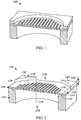
- FIG. 1 is a perspective cross-sectional view of a MEMS acoustic transducer that does not include acoustic relief channels, according to an illustrative embodiment.
- FIG. 2 is a perspective cross-sectional view of a MEMS acoustic transducer including acoustic relief channels, according to an illustrative embodiment.
- FIG. 3 is a top cross-sectional view of the MEMS acoustic transducer of FIG. 1 , according to an illustrative embodiment.
- FIG. 4 is a top cross-sectional view of the MEMS acoustic transducer of FIG. 2 .
- FIG. 5 is a side view of the MEMS acoustic transducer of FIG. 2 .
- FIG. 6 is a perspective view of a MEMS acoustic transducer that includes cylindrical posts between the back plate and the diaphragm, according to an illustrative embodiment.
- FIG. 7 is a perspective cross-sectional view of a MEMS acoustic transducer that includes rectangular walls between the back plate and the diaphragm, according to an illustrative embodiment.
- FIG. 8 is a top cross-sectional view of the MEMS acoustic transducer of FIG. 7 .
- FIG. 9 is a flow diagram of a method of making a MEMS acoustic transducer, according to an illustrative embodiment.
- FIGS. 10A-10F are side cross-sectional views of a MEMS acoustic transducer in various stages of assembly, according to various illustrative embodiments.
- FIGS. 11A-11B are side cross-sectional views of a MEMS acoustic transducer including posts between a back plate and a diaphragm, in various stages of assembly, according to various illustrative embodiments.
- FIG. 12 is a side cross-sectional view of a microphone assembly, according to an illustrative embodiment.
- LFRO low frequency roll-off
- methods and devices are described for providing high-LFRO performance for diaphragm-on-top MEMS acoustic transducers that include a movable diaphragm and a back plate located between a transducer substrate of the MEMS acoustic transducer and the moveable diaphragm.
- the methods and devices disclosed herein may have lower sensitivity to pressure changes in a low frequency range (e.g., changes in ambient pressure).
- the MEMS acoustic transducer includes a transducer substrate, a stationary back plate disposed on a first surface of the transducer substrate, and a moveable diaphragm.
- the diaphragm is spaced apart from the back plate by an intermediate layer to form a gap between the diaphragm and the back plate.
- the intermediate layer includes an acoustic relief channel (e.g., passageway, pathway, etc.) that fluidly couples the gap to an environment surrounding the MEMS acoustic transducer (e.g., a back volume of the microphone assembly) which, advantageously, allows for faster and/or more efficient equalization of air pressure across the diaphragm (e.g., between opposite sides of the diaphragm). In high sound pressure level applications, quicker equalization of pressures across the diaphragm increases the sound quality output from the microphone assembly.
- an acoustic relief channel e.g., passageway, pathway, etc.
- the intermediate layer includes a sacrificial layer (e.g., an oxide layer) that couples the diaphragm to the back plate.
- the acoustic relief channel can be formed into the sacrificial layer by over-etching the sacrificial layer during manufacturing of the MEMS acoustic transducer.
- the acoustic relief channel can extend radially outward through a side of the acoustic transducer, which, advantageously, can prevent dirt and other contaminants from entering the gap between the diaphragm and the back plate (and particularly when compared to MEMS transducers that include pierced diaphragms).
- the MEMS transducer additionally includes a plurality of posts disposed proximate to the acoustic relief channel in order to support the diaphragm in the vicinity of the acoustic relief channel.
- FIG. 1 shows a perspective view of a MEMS transducer that does not include acoustic relief channels, shown as blocked transducer 200 .
- FIG. 2 shows a top view of a MEMS transducer 100 including a plurality of acoustic relief channels 126 (“unblocked transducer 100 ”), according to an illustrative embodiment.
- the MEMS transducer 100 is configured as a capacitive acoustic transducer structured to generate an electrical signal in response to acoustic disturbances incident on the MEMS transducer 100 .
- the MEMS transducer 100 includes a transducer substrate 102 , a stationary back plate 104 , and a movable diaphragm (not shown).
- the transducer substrate 102 includes an aperture 108 disposed through the transducer substrate 102 .
- the aperture 108 is shaped as a cylinder, although any other suitable shape may be used in alternative embodiments.
- the aperture 108 is structured to carry (e.g., transmit, etc.) sound energy (e.g., pressure) to at least one of the diaphragm or the back plate 104 .
- the back plate 104 is coupled to a first surface 110 of the transducer substrate 102 .
- the back plate 104 is deposited directly onto the first surface 110 .
- the back plate 104 is perforated to allow sound (e.g., air pressure) received by the aperture 108 to pass through the back plate 104 .
- the diaphragm (not shown in FIG. 2 , but shown as diaphragm 106 in FIG. 5 ) includes an opening or pierce to allow a small amount of air to pass through the diaphragm and into a back volume of a microphone assembly.
- Sound energy e.g., sound waves, acoustic disturbances, etc.
- the change in distance results in a corresponding change in capacitance between conductive materials disposed on or within the diaphragm and the back plate 104 .
- An electrical signal representative of the change in capacitance may be generated and transmitted to other portions of the microphone assembly, such as an integrated circuit, for processing.
- the diaphragm is oriented parallel (or substantially parallel) to the back plate 104 and is spaced apart from the back plate 104 to form a gap 112 .
- the diaphragm is indirectly coupled to the back plate 104 by the intermediate layer 114 (e.g., an intervening layer) and is spaced apart from the back plate 104 by an intermediate layer 114 .
- a first side 116 of the intermediate layer 114 is coupled to the back plate 104 .
- a second side 120 of the intermediate layer 114 is coupled to the diaphragm along at least a portion of a perimeter 118 of the diaphragm.
- a height 122 of the intermediate layer 114 (e.g., an axial height of the intermediate layer 114 parallel to a central axis 124 of the aperture 108 ) is approximately equal to a distance between the diaphragm and the back plate 104 (e.g., a height of the gap 112 ).
- the intermediate layer 114 includes a sacrificial layer (e.g., an oxide layer, a phosphosilicate glass (PSG) layer, a nitride layer, or any other suitable material) that is deposited or otherwise formed onto the back plate 104 .
- the intermediate layer 114 is integrally formed with the transducer substrate 102 as a single unitary structure (e.g., such that the intermediate layer 114 forms a portion of the transducer substrate 102 ).
- the intermediate layer 114 includes a plurality of acoustic relief channels 126 .
- the intermediate layer 114 may include additional and/or fewer acoustic relief channels 126 .
- Each one of the acoustic relief channels 126 fluidly couples the gap 112 to an environment surrounding the MEMS transducer 100 (e.g., a back volume of a microphone assembly), thereby allowing air to pass freely between the gap 112 and the environment.
- the acoustic relief channels 126 provide barometric relief between air on opposing sides of the diaphragm, which reduces the sensitivity of the MEMS transducer 100 at low frequencies to a greater extent than can be achieved by using a pierced diaphragm alone.
- the acoustic relief channels 126 are etched into the intermediate layer 114 using a wet or dry etching process (e.g., reactive ion etching (RIE), deep RIE (DRIE), focused ion beam etching (FIB), etc.) or any other suitable etching process.
- RIE reactive ion etching
- DRIE deep RIE
- FIB focused ion beam etching
- FIG. 3 shows a top view of the blocked transducer 200 , which does not include acoustic relief channels.
- FIG. 4 shows a top view of the MEMS transducer 100 of FIG. 2 (“unblocked transducer 100 ”).
- Both the blocked transducer 200 and the unblocked transducer 100 are shown at a cross-section through an intermediate layer ( 214 , 114 ) between the back plate and the diaphragm.
- an intermediate layer 214 , 114
- a central portion of the intermediate layer 214 is removed in order to separate or otherwise “release” the diaphragm from the back plate.
- the intermediate layer 214 may be removed using a timed dry etch process (e.g., an RIE or DRIE process) in which a chemical solution is applied to the intermediate layer 214 for a predefined period of time until a portion of the intermediate layer 214 that covers the perforations in the back plate is removed.
- the acoustic relief channels 126 are formed into the intermediate layer 214 by over-etching the intermediate layer 114 during the release operation.
- the acoustic relief channels 126 are formed by increasing the period of time during which the central portion of the intermediate layer 114 is exposed to the chemical etching solution.
- the etching solution removes the intermediate layer 114 along a radial direction relative to the central axis 124 of the MEMS transducer 100 (e.g., the central axis 124 of the aperture 108 shown in FIG. 1 ). As shown in FIG.
- the etching operation forms a total of four acoustic relief channels 126 that are spaced equally about the perimeter 118 of the diaphragm 106 (e.g., at approximately 90° increments).
- the etching operation separates the intermediate layer 114 into a plurality of intermediate layer pieces 128 , each disposed proximate to an outer corner region of the MEMS transducer 100 .
- each one of the intermediate layer pieces 128 is triangular and includes an arcuate inner surface 130 (e.g., a curved inner surface).
- a radius 132 of each one of the arcuate inner surfaces 130 relative to the central axis 124 of the aperture 108 , is approximately equal.
- each one of the arcuate inner surfaces 130 varies depending on the period of time that the chemical etching solution is exposed to the intermediate layer 114 . Increasing the radius of each one of the arcuate inner surfaces 130 increases the LFRO of the transducer.
- the acoustic relief channels 126 can increase the LFRO by as much as a few kHz relative to the blocked transducer 200 with a pierced diaphragm (e.g., an unblocked transducer 100 having acoustic relief channels 126 that cover approximately 40% of a perimeter of the diaphragm can increase the LFRO of a pierced diaphragm MEMS by as much as two orders of magnitude in some embodiments, from approximately 100 Hz to approximately 10 kHz).
- each one of the intermediate pieces 128 are 3-sided prisms.
- the acoustic relief channels 126 may be selectively etched into the intermediate layer 114 using a secondary operation that is separate from the release operation.
- the acoustic relief channels 126 may be etched into the intermediate layer 114 using a wet etch process (e.g., using buffered hydrofluoric acid (BHF)) from an outer surface of the intermediate layer 114 .
- BHF buffered hydrofluoric acid
- the acoustic relief channels 126 may be machined into the intermediate layer 114 via a drilling operation.
- the acoustic relief channels 126 may be formed by laser cutting horizontal passages from an outer surface of the intermediate layer 114 after the diaphragm has been released from the back plate 104 (e.g., after etching the intermediate layer 114 to form the gap 112 between the diaphragm and the back plate 104 ).
- FIG. 5 shows a side cross-sectional view of the MEMS transducer 100 including the diaphragm 106 .
- Each one of the acoustic relief channels 126 includes a through-hole that extends radially outward (e.g., horizontally, into and out of the page as shown in FIG. 6 ) through an exterior surface of the MEMS transducer 100 .
- the through-hole is shaped as a rectangular window. In other embodiments, the shape and/or size of the acoustic relief channels 126 may be different.
- FIG. 6 depicts a MEMS transducer 300 that includes a plurality of posts 336 disposed within each one of a plurality of acoustic relief channels 326 .
- the posts 336 are structured to support a diaphragm within each of the acoustic relief channels 326 in order to increase the robustness of the MEMS transducer 300 .
- the posts 336 extend between a back plate 304 of the MEMS transducer 300 and a diaphragm (not shown).
- the posts 336 are integrally formed with the diaphragm as a single unitary structure. As shown in FIG.
- each one of the posts 336 is a cylinder extending from an upper surface 340 of the back plate 304 in substantially perpendicular orientation relative to the upper surface 340 .
- the size, arrangement, and position of the posts 336 may be different.
- FIGS. 7 and 8 depict a MEMS transducer 400 having posts 436 that are rectangular walls. Each one of the rectangular walls extends radially outward through at least a portion 440 (e.g., an outer portion proximate to an outer perimeter of a back plate 404 and the diaphragm) of a corresponding one of a plurality of acoustic relief channels 426 . As shown in FIG.
- a length 442 of each of the posts 436 in a substantially radial direction (e.g., away from a central axis 424 of the MEMS transducer 400 ), increases gradually with increasing distance from a central position 444 within each acoustic relief channel 426 .
- a thickness of each one of the rectangular walls 438 normal to a flow direction through each acoustic relief channel 426 is much less than a width of each acoustic relief channel 426 in order to minimize pressure drop through each acoustic relief channel 426 .
- FIG. 9 is a flow diagram of a method 500 of making a MEMS transducer.
- the MEMS transducer may be the same or similar to the MEMS transducer 100 of FIG. 2 (or, alternatively, the MEMS transducer 300 , 400 of FIGS. 6 and 7-8 , respectively).
- Various steps of the method 500 are illustrated conceptually in FIGS. 10A-10F . For simplicity, similar numbering is used to identify similar components.
- a transducer substrate 102 is provided (see FIG. 10A ).
- the transducer substrate 102 may be formed from silicon, silicon oxide, glass, Pyrex, quartz, ceramics, or any other suitable material.
- a back plate 104 is deposited onto a first surface 110 of the transducer substrate 102 .
- the back plate 104 may be formed from a low stress material, for example low stress silicon nitride (LSN), low stress oxide, or any other suitable material.
- Operation 504 may include depositing the back plate 104 onto the transducer substrate 102 using physical vapor deposition (PVD), chemical vapor deposition (CVD), low pressure chemical vapor deposition (LPCVD), plasma enhanced CVD (PECVD), atomic layer deposition (ALD), any other suitable process or a combination thereof.
- the back plate 104 may be relatively inflexible relative to a diaphragm 106 to be formed on the transducer substrate 102 .
- the method 500 may further include depositing a conducting layer 140 such as polysilicon, gold, platinum, or the any other suitable material onto the back plate 104 .
- the method 500 may additionally include forming apertures through the back plate 104 and the conducting layer 140 , for example, by using a wet or dry etching process.
- the conducting layer may also be etched to form an electrical contact on the back plate 104 .
- an intermediate layer 114 is deposited onto one of the back plate 104 and/or the conducting layer 140 such that the intermediate layer 114 covers an upper surface of the back plate 104 .
- FIG. 10B shows the transducer substrate 102 , the perforated back plate 104 and conductive layer 140 , and the intermediate layer 114 after step 506 .
- the method 500 may additionally include depositing an additional (second) intermediate layer 142 onto the first intermediate layer 114 and/or an additional (second) conductive layer 144 onto one of the first or second intermediate layers 114 .
- the method 500 may further include heating the MEMS transducer 100 to a temperature that is higher than a glass transition temperature for at least one of the intermediate layers 114 , thus causing the at least one intermediate layer 114 to flow and round-off the corners thereof.
- the method 500 includes selectively etching the intermediate layer 114 to form a recessed area 138 or a plurality of recessed areas 138 extending to an upper surface of the back plate 104 (operation 508 ).
- Operation 508 is depicted conceptually in FIGS. 11A and 11B .
- a recessed area 138 is formed proximate to a perimeter of the MEMS transducer 100 on either side of the MEMS transducer 100 .
- the recessed areas 138 may be sized to accommodate the posts 336 , 436 that structurally support the diaphragm 106 proximate to the acoustic relief channels 126 .
- the recessed areas 138 may be circular, rectangular, or any other suitable shape.
- Operation 508 may additionally include masking the MEMS transducer 100 to position each of the recessed areas 138 adjacent to an area where the acoustic relief channels 126 will be located.
- a diaphragm material is deposited onto the intermediate layer 114 (onto the second intermediate layer 142 and the second conductive layer 144 as shown in FIG. 10D ).
- a first portion of the diaphragm material forms the diaphragm 106 , which may be approximately the same as a shape of an upper surface of the intermediate layer 114 .
- a second portion of the diaphragm material is deposited into the recessed areas 138 .
- This second portion of the diaphragm material forms posts that help support the diaphragm 106 in the area where the acoustic relief channels 126 will be located (e.g., such as the posts 336 and 436 of FIGS. 6 and 7-8 , respectively).
- the method 500 additionally includes selectively etching the second portion to form the posts 336 , 436 in the area where the acoustic relief channels 126 will be located.
- the transducer substrate 102 is etched to form an aperture 108 into the transducer substrate 102 (see FIG. 10E ).
- the etching operation may be performed from a second surface of the transducer substrate 102 , opposite to the first surface 110 and may remove material along a central axis of the transducer substrate 102 .
- the diaphragm 106 is released from the back plate 104 . Operation 512 may include performing a back-side etch through the aperture 108 of the transducer substrate 102 .
- Operation 512 may additionally include removing a central portion of the intermediate layer 114 between the diaphragm 106 and the back plate 104 to form the gap 112 between the diaphragm 106 and the back plate 104 .
- Operation 512 may include performing the etching operation for a first predefined time period until the intermediate layer 114 is removed from above the apertures (e.g., a perforated portion) in the back plate 104 .
- the intermediate layer 114 is over-etched to form a plurality of acoustic relief channels 126 (see FIG. 10F , which also shows the MEMS transducer 100 after operation 512 ). In the area of the acoustic relief channels 126 , the intermediate layer 114 has been removed completely by operation 514 . It should be understood, however, that pieces of the intermediate layer 114 remain to support the diaphragm 106 in position with respect to the back plate 104 (e.g., near the corners of the MEMS transducer 100 as shown in FIG. 4 ). The remaining pieces of the intermediate layer 114 are not shown in the cross-sectional view of FIG. 10F .
- Operation 514 may include continuing the back-side etch operation of block 512 for a second predefined time period beyond the first predefined time period.
- the second predefined time period may be a time that is required (from the end of the first predefined time period) in order to form a through-hole channel between the gap 112 and an environment surrounding the MEMS transducer 100 (in at least one location along a perimeter of the MEMS transducer 100 ).
- the second predefined time period may be a time required to form at least one acoustic relief channel 126 of a desired size (width, etc.).
- a size of the acoustic relief channel 126 , and the amount of LFRO associated with the MEMS transducer 100 increases with increasing etch times.
- method 500 may include additional, fewer, and/or different operations.
- the MEMS transducer (e.g., the MEMS transducer 100 of FIG. 2 ), is configured to be received within a microphone assembly, shown as assembly 600 .
- the assembly 600 includes a housing including a microphone base 602 , a cover 604 (e.g., a housing lid), and a sound port 606 .
- the microphone base 602 is a printed circuit board.
- the cover 604 is coupled to the microphone base 602 (e.g., the cover 604 may be mounted onto a peripheral edge of the microphone base 602 ). Together, the cover 604 and the microphone base 602 may form an enclosed volume 608 for the assembly 600 .
- the sound port 606 is disposed on the microphone base 602 and is structured to convey sound waves to a MEMS transducer 100 located within the enclosed volume 608 .
- the sound port 606 may be disposed on the cover 604 or on a side wall of the housing.
- the MEMS transducer 100 includes a plurality of acoustic relief channels 126 that fluidly couple both sides of the diaphragm 106 to the enclosed volume 608 .
- the assembly may form part of a compact computing device (e.g., a portable communication device, a smartphone, a smart speaker, an internet of things (IoT) device, etc.), where one, two, three or more assemblies may be integrated for picking-up and processing various types of acoustic signals such as speech and music.
- a compact computing device e.g., a portable communication device, a smartphone, a smart speaker, an internet of things (IoT) device, etc.
- IoT internet of things
- the assembly 600 additionally includes an electrical circuit disposed in the enclosed volume 608 .
- the electrical circuit includes an integrated circuit (IC) 610 .
- the IC 610 may be an application specific integrated circuit (ASIC).
- ASIC application specific integrated circuit
- the IC 610 may include another type of semiconductor die integrating various analog, analog-to-digital, and/or digital circuits.
- the MEMS transducer 100 is configured to generate an electrical signal (e.g., a voltage) at a transducer output in response to acoustic activity incident on the port 606 .
- the transducer output includes a pad or terminal of MEMS transducer 100 that is electrically connected to the electrical circuit via one or more bonding wires 612 .
- the assembly 600 can further includes electrical contacts disposed on a surface of the microphone substrate 602 outside of the cover 604 . The contacts may be electrically coupled to the electrical circuit (e.g. via bonding wires 612 ) and may be configured to electrically connect the microphone assembly 600 to one of a variety of host devices.
- any two components so associated can also be viewed as being “operably connected,” or “operably coupled,” to each other to achieve the desired functionality, and any two components capable of being so associated can also be viewed as being “operably couplable,” to each other to achieve the desired functionality.
- operably couplable include but are not limited to physically mateable and/or physically interacting components and/or wirelessly interactable and/or wirelessly interacting components and/or logically interacting and/or logically interactable components.
- the phrase “A or B” will be understood to include the possibilities of “A” or “B” or “A and B.” Further, unless otherwise noted, the use of the words “approximate,” “about,” “around,” “substantially,” etc., mean plus or minus ten percent.
Landscapes
- Engineering & Computer Science (AREA)
- Physics & Mathematics (AREA)
- Acoustics & Sound (AREA)
- Signal Processing (AREA)
- Manufacturing & Machinery (AREA)
- Multimedia (AREA)
- Microelectronics & Electronic Packaging (AREA)
- Chemical & Material Sciences (AREA)
- Analytical Chemistry (AREA)
- Computer Hardware Design (AREA)
- Health & Medical Sciences (AREA)
- Otolaryngology (AREA)
- Micromachines (AREA)
Abstract
Description
Claims (21)
Priority Applications (1)
| Application Number | Priority Date | Filing Date | Title |
|---|---|---|---|
| US16/871,027 US11197088B2 (en) | 2019-05-10 | 2020-05-10 | MEMS microphone with acoustic relief channels |
Applications Claiming Priority (2)
| Application Number | Priority Date | Filing Date | Title |
|---|---|---|---|
| US201962846173P | 2019-05-10 | 2019-05-10 | |
| US16/871,027 US11197088B2 (en) | 2019-05-10 | 2020-05-10 | MEMS microphone with acoustic relief channels |
Publications (2)
| Publication Number | Publication Date |
|---|---|
| US20200389721A1 US20200389721A1 (en) | 2020-12-10 |
| US11197088B2 true US11197088B2 (en) | 2021-12-07 |
Family
ID=73650123
Family Applications (1)
| Application Number | Title | Priority Date | Filing Date |
|---|---|---|---|
| US16/871,027 Active US11197088B2 (en) | 2019-05-10 | 2020-05-10 | MEMS microphone with acoustic relief channels |
Country Status (1)
| Country | Link |
|---|---|
| US (1) | US11197088B2 (en) |
Cited By (1)
| Publication number | Priority date | Publication date | Assignee | Title |
|---|---|---|---|---|
| US20230023306A1 (en) * | 2020-07-11 | 2023-01-26 | xMEMS Labs, Inc. | Manufacturing method of device |
Families Citing this family (1)
| Publication number | Priority date | Publication date | Assignee | Title |
|---|---|---|---|---|
| US11323823B1 (en) * | 2021-01-18 | 2022-05-03 | Knowles Electronics, Llc | MEMS device with a diaphragm having a slotted layer |
Citations (3)
| Publication number | Priority date | Publication date | Assignee | Title |
|---|---|---|---|---|
| US20160167946A1 (en) * | 2013-07-05 | 2016-06-16 | Cirrus Logic International Semiconductor Ltd. | Mems device and process |
| CN206212271U (en) * | 2016-11-18 | 2017-05-31 | 北京卓锐微技术有限公司 | Mems structure |
| US20180002167A1 (en) * | 2016-06-29 | 2018-01-04 | Infineon Technologies Ag | Micromechanical structure and method for manufacturing the same |
-
2020
- 2020-05-10 US US16/871,027 patent/US11197088B2/en active Active
Patent Citations (3)
| Publication number | Priority date | Publication date | Assignee | Title |
|---|---|---|---|---|
| US20160167946A1 (en) * | 2013-07-05 | 2016-06-16 | Cirrus Logic International Semiconductor Ltd. | Mems device and process |
| US20180002167A1 (en) * | 2016-06-29 | 2018-01-04 | Infineon Technologies Ag | Micromechanical structure and method for manufacturing the same |
| CN206212271U (en) * | 2016-11-18 | 2017-05-31 | 北京卓锐微技术有限公司 | Mems structure |
Cited By (2)
| Publication number | Priority date | Publication date | Assignee | Title |
|---|---|---|---|---|
| US20230023306A1 (en) * | 2020-07-11 | 2023-01-26 | xMEMS Labs, Inc. | Manufacturing method of device |
| US12404166B2 (en) * | 2020-07-11 | 2025-09-02 | xMEMS Labs, Inc. | Manufacturing method of device |
Also Published As
| Publication number | Publication date |
|---|---|
| US20200389721A1 (en) | 2020-12-10 |
Similar Documents
| Publication | Publication Date | Title |
|---|---|---|
| US11617042B2 (en) | Acoustic transducers with a low pressure zone and diaphragms having enhanced compliance | |
| US11053117B2 (en) | MEMS component and production method for a MEMS component | |
| US10433068B2 (en) | MEMS acoustic transducer with combfingered electrodes and corresponding manufacturing process | |
| CN112689228B (en) | MEMS transducer, MEMS device and microphone assembly | |
| US8705777B2 (en) | MEMS microphone and method of manufacturing the same | |
| CN110290450B (en) | Micro-electromechanical sensor | |
| US11274034B2 (en) | Acoustic relief in MEMS | |
| US7348646B2 (en) | Micromechanical capacitive transducer and method for manufacturing the same | |
| KR20110132562A (en) | MEMS device with leakage path | |
| US11197088B2 (en) | MEMS microphone with acoustic relief channels | |
| CN111277937B (en) | MEMS microphone and manufacturing method thereof | |
| US11716578B2 (en) | MEMS die with a diaphragm having a stepped or tapered passage for ingress protection | |
| CN201742550U (en) | Capacitance minitype silicon microphone | |
| US11323823B1 (en) | MEMS device with a diaphragm having a slotted layer | |
| US11780726B2 (en) | Dual-diaphragm assembly having center constraint | |
| US10993044B2 (en) | MEMS device with continuous looped insert and trench | |
| US11528546B2 (en) | Sealed vacuum MEMS die | |
| WO2018002565A1 (en) | Mems devices and processes |
Legal Events
| Date | Code | Title | Description |
|---|---|---|---|
| AS | Assignment |
Owner name: KNOWLES ELECTRONICS, LLC, ILLINOIS Free format text: ASSIGNMENT OF ASSIGNORS INTEREST;ASSIGNORS:NADERYAN, VAHID;MOHAMMADI, MOHAMMAD;LLAMAS-YOUNG, EVAN;REEL/FRAME:052619/0405 Effective date: 20190530 |
|
| FEPP | Fee payment procedure |
Free format text: ENTITY STATUS SET TO UNDISCOUNTED (ORIGINAL EVENT CODE: BIG.); ENTITY STATUS OF PATENT OWNER: LARGE ENTITY |
|
| STPP | Information on status: patent application and granting procedure in general |
Free format text: APPLICATION DISPATCHED FROM PREEXAM, NOT YET DOCKETED |
|
| STPP | Information on status: patent application and granting procedure in general |
Free format text: DOCKETED NEW CASE - READY FOR EXAMINATION |
|
| STPP | Information on status: patent application and granting procedure in general |
Free format text: NON FINAL ACTION MAILED |
|
| STPP | Information on status: patent application and granting procedure in general |
Free format text: RESPONSE TO NON-FINAL OFFICE ACTION ENTERED AND FORWARDED TO EXAMINER |
|
| STPP | Information on status: patent application and granting procedure in general |
Free format text: NOTICE OF ALLOWANCE MAILED -- APPLICATION RECEIVED IN OFFICE OF PUBLICATIONS |
|
| STPP | Information on status: patent application and granting procedure in general |
Free format text: PUBLICATIONS -- ISSUE FEE PAYMENT VERIFIED |
|
| STCF | Information on status: patent grant |
Free format text: PATENTED CASE |
|
| MAFP | Maintenance fee payment |
Free format text: PAYMENT OF MAINTENANCE FEE, 4TH YEAR, LARGE ENTITY (ORIGINAL EVENT CODE: M1551); ENTITY STATUS OF PATENT OWNER: LARGE ENTITY Year of fee payment: 4 |