US11196942B2 - Image processing device and method, and medical observation device comprising such an image processing device, using an intensity or brightness-dependent variation of a pseudocolor pattern characteristic - Google Patents
Image processing device and method, and medical observation device comprising such an image processing device, using an intensity or brightness-dependent variation of a pseudocolor pattern characteristic Download PDFInfo
- Publication number
- US11196942B2 US11196942B2 US16/739,189 US202016739189A US11196942B2 US 11196942 B2 US11196942 B2 US 11196942B2 US 202016739189 A US202016739189 A US 202016739189A US 11196942 B2 US11196942 B2 US 11196942B2
- Authority
- US
- United States
- Prior art keywords
- digital
- pattern
- pseudocolor
- image
- intensity
- Prior art date
- Legal status (The legal status is an assumption and is not a legal conclusion. Google has not performed a legal analysis and makes no representation as to the accuracy of the status listed.)
- Active
Links
Images


Classifications
-
- G—PHYSICS
- G06—COMPUTING OR CALCULATING; COUNTING
- G06T—IMAGE DATA PROCESSING OR GENERATION, IN GENERAL
- G06T7/00—Image analysis
- G06T7/30—Determination of transform parameters for the alignment of images, i.e. image registration
- G06T7/33—Determination of transform parameters for the alignment of images, i.e. image registration using feature-based methods
-
- G06T11/10—
-
- A—HUMAN NECESSITIES
- A61—MEDICAL OR VETERINARY SCIENCE; HYGIENE
- A61B—DIAGNOSIS; SURGERY; IDENTIFICATION
- A61B1/00—Instruments for performing medical examinations of the interior of cavities or tubes of the body by visual or photographical inspection, e.g. endoscopes; Illuminating arrangements therefor
- A61B1/00002—Operational features of endoscopes
- A61B1/00004—Operational features of endoscopes characterised by electronic signal processing
- A61B1/00009—Operational features of endoscopes characterised by electronic signal processing of image signals during a use of endoscope
- A61B1/000095—Operational features of endoscopes characterised by electronic signal processing of image signals during a use of endoscope for image enhancement
-
- A—HUMAN NECESSITIES
- A61—MEDICAL OR VETERINARY SCIENCE; HYGIENE
- A61B—DIAGNOSIS; SURGERY; IDENTIFICATION
- A61B1/00—Instruments for performing medical examinations of the interior of cavities or tubes of the body by visual or photographical inspection, e.g. endoscopes; Illuminating arrangements therefor
- A61B1/00002—Operational features of endoscopes
- A61B1/00043—Operational features of endoscopes provided with output arrangements
- A61B1/00045—Display arrangement
-
- A—HUMAN NECESSITIES
- A61—MEDICAL OR VETERINARY SCIENCE; HYGIENE
- A61B—DIAGNOSIS; SURGERY; IDENTIFICATION
- A61B1/00—Instruments for performing medical examinations of the interior of cavities or tubes of the body by visual or photographical inspection, e.g. endoscopes; Illuminating arrangements therefor
- A61B1/06—Instruments for performing medical examinations of the interior of cavities or tubes of the body by visual or photographical inspection, e.g. endoscopes; Illuminating arrangements therefor with illuminating arrangements
- A61B1/0638—Instruments for performing medical examinations of the interior of cavities or tubes of the body by visual or photographical inspection, e.g. endoscopes; Illuminating arrangements therefor with illuminating arrangements providing two or more wavelengths
-
- A—HUMAN NECESSITIES
- A61—MEDICAL OR VETERINARY SCIENCE; HYGIENE
- A61B—DIAGNOSIS; SURGERY; IDENTIFICATION
- A61B90/00—Instruments, implements or accessories specially adapted for surgery or diagnosis and not covered by any of the groups A61B1/00 - A61B50/00, e.g. for luxation treatment or for protecting wound edges
- A61B90/20—Surgical microscopes characterised by non-optical aspects
-
- G—PHYSICS
- G06—COMPUTING OR CALCULATING; COUNTING
- G06T—IMAGE DATA PROCESSING OR GENERATION, IN GENERAL
- G06T7/00—Image analysis
- G06T7/0002—Inspection of images, e.g. flaw detection
- G06T7/0012—Biomedical image inspection
-
- G—PHYSICS
- G06—COMPUTING OR CALCULATING; COUNTING
- G06T—IMAGE DATA PROCESSING OR GENERATION, IN GENERAL
- G06T7/00—Image analysis
- G06T7/90—Determination of colour characteristics
-
- H—ELECTRICITY
- H04—ELECTRIC COMMUNICATION TECHNIQUE
- H04N—PICTORIAL COMMUNICATION, e.g. TELEVISION
- H04N5/00—Details of television systems
- H04N5/222—Studio circuitry; Studio devices; Studio equipment
- H04N5/262—Studio circuits, e.g. for mixing, switching-over, change of character of image, other special effects ; Cameras specially adapted for the electronic generation of special effects
- H04N5/2621—Cameras specially adapted for the electronic generation of special effects during image pickup, e.g. digital cameras, camcorders, video cameras having integrated special effects capability
-
- G—PHYSICS
- G06—COMPUTING OR CALCULATING; COUNTING
- G06T—IMAGE DATA PROCESSING OR GENERATION, IN GENERAL
- G06T2207/00—Indexing scheme for image analysis or image enhancement
- G06T2207/10—Image acquisition modality
- G06T2207/10024—Color image
-
- G—PHYSICS
- G06—COMPUTING OR CALCULATING; COUNTING
- G06T—IMAGE DATA PROCESSING OR GENERATION, IN GENERAL
- G06T2207/00—Indexing scheme for image analysis or image enhancement
- G06T2207/10—Image acquisition modality
- G06T2207/10056—Microscopic image
- G06T2207/10061—Microscopic image from scanning electron microscope
-
- G—PHYSICS
- G06—COMPUTING OR CALCULATING; COUNTING
- G06T—IMAGE DATA PROCESSING OR GENERATION, IN GENERAL
- G06T2207/00—Indexing scheme for image analysis or image enhancement
- G06T2207/10—Image acquisition modality
- G06T2207/10068—Endoscopic image
Definitions
- the invention relates to an image processing device for a medical observation device, such as a microscope or endoscope, to a medical observation device comprising such an image processing device, and to an image processing method, for example, a microscopy or endoscopy method.
- a region of interest may, for example, be a part of an observed tissue or an observed cell, which can be discerned by its optical characteristics, such as reflectance or fluorescence, and which needs to be identified for carrying out a further processing step.
- the region of interest may for example be a structure, such as a blood vessel or a tumor. In case of a tumor, the further processing step may be a biopsy or an excision.
- the fluorescence intensity in an area may be just below a threshold which would clearly mark it as a tumor.
- the intensity or brightness color of an area may be just below a threshold which would clearly mark it as a blood vessel.
- an image processing device for identifying and/or displaying such ambiguous regions of interest.
- an image processing device which comprises an image processor, wherein the image processor is configured to obtain a digital pseudocolor pattern, the digital pseudocolor pattern having a pattern characteristic and comprising a regularly varying pseudocolor, to combine the digital pseudocolor pattern with an input area of a retrieved digital input image, thus forming a patterned region, to vary the pattern characteristic and the location in the patterned region depending on one of the intensity and brightness at a corresponding location in the input area of at least one of the digital input images and a further retrieved digital input image, and to output at least one digital output image comprising the patterned region.
- a medical observation method which comprises such an image processing device, a camera system configured to record one or more digital input images, and at least one display device configured to display the at least one digital output image.
- a preferred embodiment of the medical observation device is a microscope, such as a laboratory microscope, which may be used for investigating cell structures, a surgical microscope for performing surgery, in particular on the human body, e.g. neurosurgery or eye surgery, or an endoscope, in particular a surgical endoscope.
- an image processing method which comprises the steps of retrieving one or more digital input images; generating at least one digital output image from the one or more digital input images; and outputting the at least one digital image for at least one of displaying and further processing; wherein the step of generating the at least one digital output image from the digital input image comprises the steps of; combining a digital pseudocolor with at least one input area of at least one of the one or more digital input images to create a patterned region, wherein the digital pseudocolor pattern has a pattern characteristic; and adjusting the pattern characteristic at a location of the patterned region depending on one of an intensity and brightness at a corresponding location in the input area of at least one of the one or more digital input images.
- the above method and devices allow to quickly differentiate between ambiguous and unambiguous regions of interest.
- care must be taken to mark them differently from an area which meets all the criteria for a region of interest. If an ambiguous region of interest and an unambiguous region of interest would be marked in the same manner, the user may not be able to recognize the difference and draw wrong conclusions about further steps.
- the medical observation device is a surgical microscope or endoscope, a surgeon may wrongly decide that an ambiguous region of interest is a tumor which needs to be excised.
- the ambiguous region of interest is in fact not a tumor, but an artifact, removal of the erroneously-marked tumor may pose a serious risk to the patient. Further, if all dubious regions of interest need to be confirmed manually, e.g. by varying the criteria for displaying the region of interest, the surgery will become more time-consuming and exhausting for the surgeon.
- the digital pseudocolor pattern is not uniformly applied, but changed according to the content of the area where it is applied. This allows ambiguous regions of interest to be displayed differently from unambiguous regions of interest.
- the intensity of the fluorescence in the input area may be decisive on whether an area is classified as a region of interest or not. Varying the pseudocolor pattern on intensity or brightness allows a user to immediately recognize a region of interest, which may not clearly be a tumor.
- Another example is e.g. a blood vessel, which may be identified by its color. Blood vessels, where the intensity in a specific color range is not sufficiently high enough to be unambiguously qualified as a blood vessel, can thus be marked with a different pseudocolor pattern characteristic.
- the above image processing device, medical observation device and method thus greatly improve handling of the medical observation device by positively interacting with the user using technical effects.
- the above image processing device, medical observation device and method may be further improved by comprising one or more of the additional features which are described in the following. As it is explained below, each of these additional features has its own technical effect and may be independently combined with any one of the other additional features.
- the additional features may be indiscriminately applied to the image processing device, the medical observation device and/or the image processing method. It is to be understood, that whenever a process step is explained in the following without explicitly mentioning the image processing system, the image processing device may be correspondingly configured to carry out this processing step. Vice versa, if it is stated that the image processor is configured to carry out a process step, this process step may also be part of an embodiment of the image processing method comprising or requiring the image processing device.
- the image processor may be configured in one embodiment to obtain the one or more digital input images by retrieving them from at least one of a camera system and a memory device.
- the camera system may comprise a CMOS or a CCD camera.
- the camera system may, alternatively or cumulatively, comprise an RGB camera, a multispectral camera and/or a hyperspectral camera.
- the camera system may further comprise a camera which is configured to record one or more digital input images in one or more wavelength bands comprising white light, IR, NIR and/or UV light.
- the memory device may comprise a hard disk drive, a memory card, a memory stick, a memory bank, and/or at least one of magnetic and optical disks.
- the memory device may further comprise volatile and/or volatile memory.
- the location, at which one of the intensity and brightness in the input area is determined, may be a single pixel in one of the one or more digital output images.
- the location may also be a set of preferably contiguous pixels in one or more digital input images.
- a location in the input area may be considered to correspond to the location in the patterned region if it has at least one of the same geometrical position within the at least one digital input image and the at least one digital output image as derived from the at least one digital input image, and/or the same geometrical position within the same image feature as extracted by a pattern recognition algorithm from the one or more digital input images.
- the input area may be a feature in the one or more digital input images that has been extracted, in particular by the image processing device, using a pattern recognition algorithm. Matching locations in the patterned region and in the input area improves the accuracy of the rendition in the one or more digital output images and makes sure that the pseudocolor pattern faithfully renders what is observed in the input area.
- obtaining a digital pseudocolor pattern may comprise at least one of retrieving the digital pseudocolor pattern, e.g. from a memory device, and generating the digital pseudocolor pattern, e.g. using a function stored in the image processing device.
- the image processor may, for example, comprise a memory, in which pre-defined digital pseudocolor patterns or pre-defined functions for generating one or more digital pseudocolor patterns are stored.
- the digital pseudocolor pattern may, in another embodiment, comprise a pseudocolor which may be stored in a memory device or which may be generated using a function.
- the function may be stored in the image processing device.
- the image processor may be configured to determine a pseudocolor of the digital pseudocolor pattern automatically from a set of stored pseudocolors.
- the pseudocolor preferably is a color which is not comprised in any of the one or more digital input images on which the one or more digital output images are based.
- the pattern characteristic distinguishes one digital pseudocolor pattern from another.
- the pattern characteristic may comprise at least one of a pseudocolor, intensity, brightness, transparency, contrast, geometric shape, temporal rate of change, and spatial rate of change of the digital pseudocolor pattern. Any of these pattern characteristics may be varied at a location depending on one of the intensity and brightness at the corresponding location in the input area.
- the digital pseudocolor pattern may be at least one of a temporally and spatially varying digital pseudocolor pattern.
- a temporally varying digital pseudocolor pattern has a temporal regularity, e.g. a dominant temporal frequency or, equivalently, rate of change, which governs the regular changes or repetitions of the digital pseudocolor pattern over time.
- a temporal regularity e.g. a dominant temporal frequency or, equivalently, rate of change
- a dominant temporal frequency is the rate at which the intensity of the pseudocolor in the patterned region changes over time.
- Such a temporal regularity may e.g. cause blinking of a digital pseudocolor pattern at a certain frequency.
- An example of a dominant spatial frequency or, equivalently, rate of change is for example the width of a hatching or the spatial distance between a recurring geometric designs.
- Temporal and spatial variation may be combined, e.g. by having a temporally and spatially varying pattern, such as a blinking and/or moving hatching.
- the pseudocolor intensity at the location in the patterned region may change periodically with a frequency that depends on the intensity or brightness at the corresponding location in the input area.
- the change over time of the pseudocolor intensity may be continuous, e.g. sinusoidal, or abrupt, e.g. step-wise.
- the amplitude of the temporal change and/or the maximum or minimum intensity or brightness may also depend on the intensity or brightness at the corresponding location in the input area.
- a first pattern characteristic of the digital pseudocolor pattern of a location in the patterned region may be determined depending on the intensity or brightness at the matching location in the input area and second, different pattern characteristic of the digital pseudocolor pattern in the patterned region may depend on the average intensity or brightness in the input region.
- a first pattern characteristic at a location of the pseudocolor pattern in the patterned region may depend on a local characteristic at the matching location in the input area and a second, different pattern characteristic of the pseudocolor pattern in the patterned region may depend on a global characteristic of the input area.
- the global characteristic may be based on an image area which is larger than the area of a local characteristic. For example, the local characteristic may be determined using only a single pixel whereas the global characteristic may be determined using a plurality of pixels, where the plurality of pixels may include the single pixel for the local characteristic.
- the first pattern characteristic may be at least one of an intensity or brightness
- a contrast of the pseudocolor of the digital pseudocolor pattern and the second pattern characteristic may be at least one of a spatial and temporal rate of change of the digital pseudocolor pattern, such as a size of the pattern and a blinking frequency.
- a digital input image may comprise one or more color channels.
- a single color channel may constitute a digital input image.
- a position of a spatially varying pseudocolor pattern may be periodically shifted in subsequent digital output images.
- a geometry or topology of the spatially varying pattern may remain constant over time, e.g. in the subsequent digital output images, the geometry or topology comprising e.g. the width, distance and/or shape of the digital pseudocolor pattern.
- Such a temporally and spatially varying pattern may be perceived as moving in one direction by an observer.
- a time series of digital output images may be computed or derived from a single digital output image.
- a temporally varying pattern may be computed and displayed for one or more still input images.
- a temporally varying pattern is computed for each image in a time series of digital input images based on one or more subsequent digital input images.
- the image processor is configured to compute the at least one digital output image comprising the digital pseudocolor pattern in real time. This allows an observer to react quickly and in time for critical changes in the digital input images, in particular if the digital input images represent a live stream of digital input images.
- a single digital output image may be computed for each digital input image.
- the frame rate of the digital output images may correspond to the frame rate of the digital input images.
- the digital pseudocolor pattern may, in another embodiment, contain recurring geometric elements, e.g. polygons, stripes and/or circles.
- the digital pseudocolor pattern may, according to an alternative or cumulative embodiment, comprise pseudocolored areas and non-pseudocolored areas, and/or it may comprise pseudocolored areas and areas that do contain a different pseudocolor, or areas that contain a different intensity or brightness of the pseudocolor. For example, an ambiguous region of interest, which may qualify for two different kind of regions of interest may be marked in two different pseudocolors that are assigned to the two different kinds respectively.
- the pseudocolor pattern in the patterned region may contain the two pseudocolors of the two fluorophores, e.g. in a two-colored hatching.
- a two-colored, e.g. red and blue, digital pseudocolor pattern may be used.
- the pseudocolor pattern in the patterned region may comprise at least one of a first pattern component and a second pattern component, the first pattern component having one of a form, pseudocolor, pseudocolor intensity and a pseudocolor brightness being different from that of the second pattern component.
- the second pattern component may have a lower pseudocolor intensity or brightness and/or different pseudocolor than the first pattern component.
- the first pattern component may be the part of a hatched pseudocolor pattern that comprises a pseudocolored region
- the second pattern component comprises the areas between the hatched lines and consequently has less or no pseudocolor intensity or brightness.
- the difference between the pseudocolor intensity or brightness of the first pattern component and the second component, or the contrast between the first and the second pattern component may depend on one of an intensity and brightness in the input area of one or more digital input images.
- the contrast i.e. the visibility of the pseudocolor pattern depends on the intensity or brightness of the input area.
- the contrast of the digital pseudocolor pattern may increase with the intensity or brightness in the input area.
- an input area which has only low intensity or brightness and thus would hardly be visible or discernible would contain a pattern having low contrast.
- the visibility of the pattern is increased as compared to the unpatterned input area due to the spatial and/or temporal frequencies in the pattern, it is not overly exaggerated.
- the risk is further reduced that a pseudocolor pattern based on an input area having weak intensity or brightness is confused with an input pattern based on an input area having high intensity or brightness.
- the image processor may be configured to set one of the brightness and intensity of the at least one pseudocolor at a location in the patterned region proportional to one of the brightness and intensity at a corresponding location in the input area.
- the contrast of the pseudocolor pattern depends on the brightness and intensity of the corresponding location in the input area. This allows an observer to make immediate conclusions about the input area and thus about any ambiguity of the patterned region as a location of interest. For example, with decreasing brightness and intensity, the brightness and intensity of the at least one pseudocolor may decrease.
- the pseudocolor pattern comprises both a first and second pattern component
- the second pattern component does not comprise any pseudocolor.
- the image processing device may be configured to compute a pseudocolored region in the one or more digital output images in addition to the patterned region.
- the pseudocolored region may be colored in a pseudocolor without use of a digital pseudocolor pattern. More specifically, the pseudocolored area may be computed using the device and method of EP 3 205 254, which is herewith incorporated in its entirety by reference.
- the pseudocolored region in the one or more digital output images may be at a location, in which the intensity or brightness of the corresponding input area in the one or more digital input images is above a predetermined lower threshold.
- the device and method of EP 3 205 254 may also be used to merge the pseudocolor pattern with one or more digital input images.
- a high fluorescence intensity or brightness may be generated in an area where many tumorous cells are concentrated.
- a certain predetermined threshold of fluorescence intensity or brightness there is a high certainty that high fluorescence intensity marks a tumor.
- Below this upper threshold there may be an increased statistical uncertainty whether there is a tumor.
- the input area having intensities or brightnesses above the threshold will be uniformly colored using a pseudocolor without a pattern. This may be done e.g.
- the input area having intensities or brightnesses below the threshold may be used to generate the patterned area as described above.
- the patterned area thus marks ambiguous regions of interest.
- the input area, or the patterned area respectively may be determined by comprising one or more preferably contiguous pixels, of which the intensity or brightness is both below the upper predetermined threshold and above a lower predetermined threshold.
- the lower predetermined threshold may be used to avoid the inclusion of small intensities or brightness in the input area, which may be affected by noise or measurement errors.
- a digital input image may comprise a plurality of separate input areas if the threshold criteria is met at different locations.
- the one or more digital input images may comprise a fluorescence image which has been recorded in a fluorescence spectrum of at least one fluorophore; a digital white-light image recorded in white light; a digital CT image; a digital MRT image: a digital Raman microspectroscopy image; a digital ultrasound image; and any combination thereof.
- the image processor may be further configured to select as the input area an area of the digital input image only if it comprises a plurality of preferably contiguous pixels.
- the input area may be selected to be larger than a predetermined geometric shape of the digital pseudocolor pattern.
- the image processor may be configured to select as the input area, an area of the digital input area only if it comprises a predetermined minimum number of pixels in which an intensity or brightness is at least one of below and above a respective upper and lower threshold.
- the minimum size of an input area may be 3 ⁇ 3, 4 ⁇ 4, or 5 ⁇ 5 pixels.
- the image processor may be further configured to apply a different minimum size criterion or filter of the input area depending on an average intensity or brightness of the one or more digital input images in the input area and/or depending on the contrast between the input area and its immediately surrounding area.
- a different minimum size criterion or filter of the input area depending on an average intensity or brightness of the one or more digital input images in the input area and/or depending on the contrast between the input area and its immediately surrounding area.
- small, bright areas may be as visible and as relevant for a region of interest as a larger, less bright area.
- the size of the input area may thus depend on its average intensity or brightness. The larger the average intensity, the smaller the size of the input may be.
- the average intensity or brightness may be any one of a median; an arithmetic, geometric, harmonic, quadratic, cubic, generalized, weighted, truncated, winsorized and interquartile mean; a mode; a midrange; and any combination of these values.
- the image processor may, in another embodiment, be configured to compute an average intensity in the input area and in an area surrounding the input area, and, in particular, the contrast between the input area and its surroundings.
- the image processor may be configured to adjust a threshold to the minimum size of the input area depending on this difference. Using this criterion, it is considered that an input area which has an intensity or brightness that is markedly different from its surroundings, may qualify with a higher likelihood as a true region of interest.
- the surrounding area may be located in the same or a different digital input image as the digital input image in which the input area is located.
- the intensity or brightness of the input area may be computed from a digital fluorescence image.
- the intensity or brightness of the surroundings may be determined from a digital white-light image.
- the intensity or brightness in the input area may be determined from a single color channel whereas the intensity or brightness of the surroundings is determined from another color channel or a combination of color channels.
- the upper and/or lower threshold which is used to determine the input area and thus a region of interest may be computed by the image processing device as depending on the average intensity or brightness of the input area, on a contrast between an average intensity or brightness of the input area and/or a surrounding area in the same or different digital input image.
- the upper threshold may be increased in an input area, which has a high average intensity or brightness as compared to an input area which has a lower average intensity or brightness.
- the upper threshold may alternatively or additionally be increased in an input area, which has a high contrast to the surrounding area in the same or different digital input image as compared to an input area which has a lower contrast to those surroundings.
- the upper and/or lower threshold may also be determined by the image processing device depending on an overall average intensity or brightness in the digital input image where the input area is located, or another digital input image. For example, the upper and/or lower threshold may be increased if the overall intensity of the digital input image, in which the input area is located, is larger. Conversely, the upper and/or lower threshold may be decreased if the overall intensity of the digital input image, in which the input area is located, is smaller.
- the image processing device may, in another embodiment, comprise a table or function for determining at least one of a value of an upper and/or lower threshold, and a size of the input area depending on at least one of an average intensity in the input area, in the surrounding area of the same or a different digital input image, and the difference or contrast between the intensity and the input area and the surrounding area in the same or a different digital input image.
- a table or function for determining at least one of a value of an upper and/or lower threshold, and a size of the input area depending on at least one of an average intensity in the input area, in the surrounding area of the same or a different digital input image, and the difference or contrast between the intensity and the input area and the surrounding area in the same or a different digital input image.
- the image processor may be configured to vary a pattern characteristic depending on the size of the input area.
- the image processor may be configured to adapt the geometric shape of the digital pseudocolor pattern to the size of the input area, such that more than one instance of the pseudocolor pattern fits into the input area.
- the image processing device may be configured to select the pseudocolor pattern dependent on the input area having the smallest size.
- the image processor may be adapted to automatically select between a temporally and a spatially varying pattering depending on the minimum or average size of the input area. For example, if the input area is small, a blinking pseudocolor with no spatial regularity may be used.
- the image processing device may be configured to apply the pseudocolor pattern in the patterned region only if the patterned region comprises at least a predetermined number of pixels.
- the image processor may be configured to determine at least one of the number of pixels, a dimension such as the width and/or length, and an aspect ratio of the input area and/or the patterned region.
- the image processor may be configured to compare this value with a predetermined value to determine whether the patterned region has at least one of a minimum number of pixels, dimensions, and aspect ratio.
- the patterned region or the input area may comprise an area which would otherwise not be patterned, if this area is surrounded by the input area and does not exceed a predetermined size. If, for example, an otherwise bright input area comprises a dark speck, it may be preferred for easier recognition to also pattern this dark speck if it is only small.
- the image processor may further be configured to adjust the pattern characteristic at a location at a border of the patterned region depending on one of the intensity and brightness at least one neighboring location outside the patterned region of the at least one digital output image.
- the intensity and brightness of the pseudocolor may be varied by the image processing device depending on the intensity or brightness at the least one neighboring location. This allows to smoothly adapt the intensity or brightness of the patterned region to the surroundings of the input area.
- the at least one neighboring location outside the patterned region must not necessarily be located in the same digital input image as the input area, but may be located in a different digital input image. This prevents the intensity or brightness from abruptly changing at the border of the patterned region, where in fact, the intensity or brightness of the input area tapers smoothly. Thus, the border is not artificially highlighted.
- the image processor may be configured to create a predetermined difference, or contrast, between one of the intensity and brightness of the at least one pseudocolor at a location at the border of the patterned region and at least one neighboring location outside the patterned region. This allows to maintain a specific contrast and thus visibility between the patterned region and its surroundings.
- the image processor may be further configured to retrieve one of the one or more digital input images as a digital white-light image representing an object recorded in white light, and another one of the one or more digital input images as a digital fluorescence image representing the object recorded in the fluorescence spectrum of at least one fluorophore; to determine the input area in the digital fluorescence image; to merge the pseudocolor pattern with the digital white-light image, varying one of the brightness and intensity of the pseudocolor pattern at a location in the patterned region depending on one of the brightness and intensity of the corresponding location in the digital fluorescence image.
- the merging may be performed using the device and method described in EP 3 205 254, as described above.
- the image processor may be further configured to create a continuous transition in one of the brightness and intensity between a location at a border of the patterned region and neighboring location at the border outside of the patterned region.
- the camera system may be configured to record at least one of the one or more digital input images in a fluorescence spectrum of at least one fluorophore as a digital fluorescence input image, and record one of the one or more digital input images in white light as a digital white light input image.
- aspects have been described in the context of an apparatus, it is clear that these aspects also represent a description of the corresponding method, where a block or device corresponds to a method step or a feature of a method step. Analogously, aspects described in the context of a method step also represent a description of a corresponding block or item or feature of a corresponding apparatus.
- Some or all of the method steps may be executed by (or using) a hardware apparatus, like for example, a processor, a microprocessor, a programmable computer or an electronic circuit. In some embodiments, some one or more of the most important method steps may be executed by such an apparatus.
- embodiments of the invention can be implemented in hardware or in software.
- the implementation can be performed using a non-transitory storage medium such as a digital storage medium, for example a floppy disc, a DVD, a Blu-Ray, a CD, a ROM, a PROM, and EPROM, an EEPROM or a FLASH memory, having electronically readable control signals stored thereon, which cooperate (or are capable of cooperating) with a programmable computer system such that the respective method is performed. Therefore, the digital storage medium may be computer readable.
- Some embodiments according to the invention comprise a data carrier having electronically readable control signals, which are capable of cooperating with a programmable computer system, such that one of the methods described herein is performed.
- embodiments of the present invention can be implemented as a computer program product with a program code, the program code being operative for performing one of the methods when the computer program product runs on a computer.
- the program code may, for example, be stored on a machine readable carrier.
- inventions comprise the computer program for performing one of the methods described herein, stored on a machine readable carrier.
- an embodiment of the present invention is, therefore, a computer program having a program code for performing one of the methods described herein, when the computer program runs on a computer.
- a further embodiment of the present invention is, therefore, a storage medium (or a data carrier, or a computer-readable medium) comprising, stored thereon, the computer program for performing one of the methods described herein when it is performed by a processor.
- the data carrier, the digital storage medium or the recorded medium are typically tangible and/or non-transitionary.
- a further embodiment of the present invention is an apparatus as described herein comprising a processor and the storage medium.
- a further embodiment of the invention is, therefore, a data stream or a sequence of signals representing the computer program for performing one of the methods described herein.
- the data stream or the sequence of signals may, for example, be configured to be transferred via a data communication connection, for example, via the internet.
- a further embodiment comprises a processing means, for example, a computer or a programmable logic device, configured to, or adapted to, perform one of the methods described herein.
- a processing means for example, a computer or a programmable logic device, configured to, or adapted to, perform one of the methods described herein.
- FIG. 1 shows a schematic representation of a possible embodiment of a medical observation
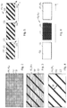
- FIGS. 2-6 show schematic representation of digital pseudocolor patterns
- FIG. 7 shows a schematic representation of merging digital input images and a digital pseudocolor pattern to obtain an output image
- FIG. 8 shows a schematic representation of an input area
- FIG. 9 shows a schematic representation of another embodiment of an input area
- FIG. 10 shows a schematic representation of a pseudocolor intensity and/or brightness variation along a line in a patterned region
- FIG. 11 shows a schematic representation of another embodiment of a pseudocolor intensity and/or brightness variation along a line in a patterned region
- FIG. 12 shows a schematic representation of input areas in a digital input image
- FIG. 13 shows a schematic representation of variants of a digital pseudocolor pattern
- FIG. 14 shows a schematic representation of a flowchart.
- an image processing device 100 as e.g. used in a medical observation device 102 , such as microscope 104 or endoscope is shown.
- the image processing device 100 comprises an image processor 106 which may be part of a general-purpose computer.
- the image processor 106 may comprise hardware, software or a combination of hardware and software. It may comprise a CPU, GPU, vector processor, FPA, and/or an ASIC.
- the image processor 106 is configured to obtain a digital pseudocolor pattern 116 .
- the digital pseudocolor pattern 116 has a pattern characteristic 118 and comprises a regularly varying pseudocolor 120 .
- the image processor 106 is further configured to combine the digital pseudocolor pattern 116 with an input area 122 of a retrieved digital input image 108 , 110 .
- a digital input image may comprise one or more color channels. A single color channel may already constitute a digital input image.
- the combination of the digital pseudocolor pattern 116 with the input area 122 and/or a matching area of one of the digital input images 108 , 110 results in a patterned region 124 .
- the image processor 106 is also configured to vary the pattern characteristic 118 at a location 126 in the patterned region 124 depending on one of the intensity and brightness at a corresponding location 128 in the input area 122 of at least one of the digital input images and a further retrieved digital input image.
- the pattern characteristic 118 may comprise at least one of the pseudocolor, intensity, brightness, transparency, contrast, geometric shape, temporal rate of change and spatial rate of change of the digital pseudocolor pattern 116 .
- the pattern characteristic 118 may, in particular, be an optical or visual characteristic, so that the various digital pseudocolor patterns 116 can be discerned visually from one another.
- Different pattern characteristics 118 allow to distinguish different pseudocolor patterns 116 from another which may be used simultaneously in one digital output image 130 . Any one pattern characteristic or any combination of these pattern characteristics 118 may be varied at the location 126 depending on one of the intensity and brightness at the corresponding location 128 in the input area 122 .
- the image processor 106 is further configured to output at least one digital output image 130 comprising the patterned region 124 .
- the image processor 106 may be configured to generate the patterned region 124 in an input area 122 , in which one of an intensity or brightness in the one or more digital input images 108 , 110 is at least one of below and above a respective upper and lower threshold.
- the intensity or brightness in the input area 122 may be computed by the image processing device 100 using an average intensity over the input area 122 .
- the average intensity may be computed using at least one of a median; an arithmetic, geometric, harmonic, quadratic, cubic, generalized, weighted, truncated, winsorized and interquartile mean, a mode, a midrange and any combination thereof.
- the input area 122 preferably comprises a plurality of pixels 128 c .
- the pixels 128 c of the plurality are preferably contiguous, i.e. form a connected area.
- the area may enclose one or more pixels 128 c , which are not part of the input area 122 , because their intensity or brightness does not meet the criterion for being an input area. This may for example be the case, if the intensity or brightness is below a lower predetermined threshold or if the intensity or brightness is above an upper predetermined threshold.
- the image processor 106 may be further configured to adjust the pattern characteristic 118 at a location 132 at the border 134 of the patterned region 124 depending on one of the intensity or brightness and at least one neighbouring location 136 outside the patterned region 124 of the at least one digital output image 130 .
- the location 128 at which one of the intensity and brightness in the input area 122 is determined, may be a single pixel 128 c .
- the matching location 126 in the patterned region 124 may also be a single pixel 126 c .
- the location 128 may comprise a set of preferably contiguous pixels 126 c in one or more digital input images 108 , 110 . In this case, the average intensity or brightness across the plurality of pixels may be determined. If more than one digital input image 108 , 110 is used to determine the intensity or brightness, matching locations 126 are used.
- the location 128 may comprise the entire input area 122 .
- a location 128 in the input area 122 corresponds to or, equivalently, matches a location 126 in the patterned region 124 if it has the same geometrical position within the at least one digital input image 108 , 110 as in the at least digital output image 130 .
- two locations 126 , 128 may be considered to match, if they have the same geometrical position within the same image feature as extracted by a pattern recognition algorithm from the one or more digital input images 108 , 110 .
- the input area 122 may be a feature 154 that has been extracted by the image processor 106 using a pattern recognition algorithm.
- An example of such a feature 154 is a blood vessel in a digital white-light image 142 , which has been recorded in white light, or a tumor which has been recorded in the fluorescence spectrum of the fluorophore 150 in a digital fluorescence image 148 .
- the image processor 106 may further be configured to create a predetermined difference between the intensity or brightness of the at least one pseudocolor 120 at a location 132 at the border 134 of the patterned region 124 and one of the intensity and brightness of at least one neighbouring location 136 outside the patterned region 124 .
- the image processor 106 may be further configured to set one of the brightness and intensity of the at least one pseudocolor 120 at a location 126 in the patterned region 124 proportional to one of the brightness and intensity at a corresponding location 128 in the input area 122 .
- the digital pseudocolor pattern 116 in the patterned region 124 may comprise a first pattern component 138 and a second pattern component 140 .
- a pseudocolor brightness or intensity of the first pattern component 138 is preferably different from the pseudocolor brightness or intensity of the second pattern component 140 .
- the first pattern component 138 and the second pattern component 140 may comprise different pseudocolors.
- the pseudocolor brightness or intensity in at least one of the first and second pattern components 138 , 140 may depend on the brightness or intensity, respectively, in the input area 122 .
- the difference between the pseudocolor intensity or brightness of the first component and that of the second pattern component at a location 126 may be dependent on the intensity and brightness at the matching location 128 in the input area 122 .
- the location 126 may have a size which comprises both pattern components 138 , 140 .
- FIGS. 2 to 6 show examples of various digital pseudocolor patterns 116 indicated as 116 a , 116 b , 116 c , 116 d , 116 e .
- the patterns 116 a - 116 e all have spatial and/or temporal regularity.
- the patterns of FIGS. 2 and 6 should not be construed to limit the variety of pseudocolor patterns 116 that may be used by the image processing device 100 in any way.
- Pseudocolor patterns 116 a - 116 d all have spatial regularity.
- a basic constituent of the digital patterns 116 a - 116 d repeats itself at a certain spatial frequency.
- the basic constituent may be of any shape, such as a polygonal shape as in pseudocolor pattern 116 a of FIG. 2 .
- the pseudocolor pattern 116 may be a hatching as the pseudocolor patterns 116 b - 116 d.
- the pattern components 138 , 140 of a pseudocolor pattern 116 a - 116 e have different pseudocolor brightness or intensity.
- One of the two components 138 , 140 in FIGS. 2 to 6 may have less intensity or brightness of the pseudocolor than the other.
- the first pattern component 138 may not contain any pseudocolor, whereas the second pattern component 140 comprises a pseudocolor.
- the first pattern component 138 comprises a pseudocolor at a lower intensity than the second pattern component 140 .
- the pseudocolor patterns 116 d - 116 e of FIGS. 5 and 6 have temporal regularity.
- the shape of the pseudocolor pattern 116 d here a hatching as an example, does not change shape, but position over time t: By shifting the position gradually from one frame 556 to the next, the impression of a pseudocolor 116 d propagating in a direction 558 may be created. By repeating a sequence of subsequent frames 556 at a certain temporal rate, or, equivalently, frequency, regularity over time t is obtained.
- the digital pseudocolor pattern 116 d of FIG. 5 has both spatial and temporal regularity.
- the digital pseudocolor pattern 116 e exhibits temporal regularity only in that the first pattern component 138 and the second pattern component 140 are displayed at a certain temporal rate of change or frequency, respectively. This creates a blinking pseudocolor pattern 116 e.
- the image processor 106 may be configured to vary at least one of a temporal and spatial rate of change of the digital pseudocolor pattern 116 depending on one of an intensity and brightness in the input area 122 .
- a distance 460 between one of the first and second pattern component 138 , 140 , or a width thereof, may depend on the intensity or brightness in the input area 122 .
- the distance 460 between the second pattern component 140 having a higher pseudocolor intensity or brightness may increase if the intensity or brightness in the input area 122 increases.
- the image processor 106 may be configured to retrieve at least one of the one or more digital input images 108 , 110 as a digital white-light image 142 .
- the digital white-light image 142 represents an object 144 recorded in white light 146 .
- the white light 146 contains enough wavelengths to faithfully render any color of the object 144 in the visible light frequencies.
- a digital white-light image 142 may be in RGB format.
- the image processor 106 may further be configured to retrieve at least another one of the one or more digital input images 108 , 110 as a digital fluorescence image 148 .
- the digital fluorescence image represents the object 144 recorded in the fluorescence spectrum of at least one fluorophore 150 . If the object contains a plurality of fluorophores, a plurality of digital fluorescence images 148 may be provided, each of the digital fluorescence images 148 preferably containing the fluorescence wavelength of a different fluorophore 150 .
- the image processing device 100 may further be configured to determine the input area 122 in the at least one digital fluorescence image 148 .
- the input area 122 may be determined to correspond to an area in a digital fluorescence image 148 in which the fluorescence brightness or intensity is above a lower threshold and below an upper threshold.
- the input area may be determined as an area in the digital fluorescence image 148 , in which the intensity or brightness is above the lower threshold, or as an area in which the intensity or brightness is below the upper threshold.
- the digital fluorescence image 148 may be normalized and/or low-pass filtered, before determining the input area.
- an input area 122 may be determined independently in each of the digital fluorescence images 148 .
- one digital fluorescence image 148 records the fluorescence spectrum of a fluorophore 150 which binds to oxygen-rich red blood cells
- determination of the input area 122 by using at least one brightness or intensity threshold may be used so that the input area 122 will correspond to an arterial blood vessel.
- another fluorophore 150 a FIG. 1
- a digital fluorescence image 148 containing the fluorescence spectrum of this other fluorophore 150 a may be used to define a tumor as an input area 122 .
- two different digital pseudocolor patterns are assigned to these two different input areas 122 which are based on different digital input images 108 , 110 , or digital fluorescence images 148 in particular.
- the two different digital pseudocolor patterns differ in at least one pattern characteristic 118 , e.g. the pseudocolor.
- the image processor 106 may further be configured to merge the pseudocolor pattern 116 with the digital white-light image 142 , wherein the brightness or intensity of the pseudocolor pattern 116 , e.g. of at least one of its components 138 , 140 at a location 126 in the patterned region 124 is set depending on the brightness or intensity of the corresponding location 128 a in the input area 122 of the digital fluorescence image 148 .
- the image processor 106 may be configured to retrieve the one or more digital input images 108 , 110 from a camera system 112 or a memory device 114 , each of which may be a part of the medical observation device 102 .
- the one or more digital input images 108 , 110 in the memory device 114 may have any appropriate data format for storing image information, such as PDF, GIF, TIF, JPEG, TGA, and/or MPG format.
- the memory device 114 may be a volatile or non-volatile memory. It may be a fixed part of the medical observation device 102 or it may be removable.
- the memory device 114 may for example be a hard disk, a memory bank, an optical disk, a memory card or a memory stick.
- the camera system 112 is preferably configured to record one or more digital input images 108 , 110 .
- the camera system 112 may be configured to record at least one of the one or more digital white-light images 142 and the one or more digital fluorescence images 148 .
- the camera system 112 may comprise at least one camera 112 a .
- the camera system 112 may comprise an RGB camera for recording white-light images such as a CCD or CMOS camera.
- the camera system 112 may, in addition or alternatively, comprise a camera for recording UV, NIR and/or IR images.
- the camera system 112 may comprise a multi-spectral or hyperspectral camera.
- the medical observation device 102 may further comprise at least one display device 152 configured to display the at least one digital output image 130 .
- the medical observation device 102 may comprise as a display device 152 , a monitor 152 a , the VR goggles 152 b , and/or an ocular 152 c .
- Any one of the display devices 152 may be stereoscopic or holographic. This allows to display digital input images 108 , 110 which are 3-dimensional, such as stereoscopic digital input images 108 , 110 .
- FIG. 7 it is shown how a digital pseudocolor pattern 116 is combined or merged with a digital input image 108 representing e.g. a digital white-light image 142 , and a digital input image 110 , representing e.g. a digital fluorescence image 148 .
- the digital white-light image 142 may be a color image or a monochrome image; the digital fluorescence image 148 may be a color image or a monochrome image.
- an input area 122 has been determined by the image processing device 100 ( FIG. 1 ).
- the combination of the digital pseudocolor pattern and the one or more digital input images 108 , 110 results in at least one digital output image 130 .
- the combination or merging function is exemplarily shown at reference numeral 762 and may employ the device and method described in EP 3 205 254 by using the digital pseudocolor pattern instead of a (constant) pseudocolor.
- the input area 122 may be determined as an area in the digital fluorescence image 148 , in which the intensity I or brightness B is above a lower threshold 764 .
- An intensity or brightness variation 766 of the pseudocolor along line 768 is shown schematically for explanatory purposes.
- the input area 122 is also indicated in the other digital input image 108 , the digital white-light image 142 .
- locations 126 and 128 are matched. This can, e.g. be accomplished by making sure that the field of views and preferably of the respective sensors which record digital input images 108 , 110 are identical. In this case, the locations 126 and 128 match if they are within the same geometrical position in their respective digital input image 108 , 110 .
- the digital pseudocolor pattern 116 is generated only for locations 128 in the input area 122 .
- An area 770 which may be enclosed by or located outside input area 122 and which does not have an intensity or brightness above the lowest lower threshold 764 , preferably is not assigned a pseudocolor pattern 116 in the one or more digital output images. The area 770 may therefore be considered as background.
- At least one pattern characteristic 118 of the digital pseudocolor pattern 116 is varied by the image processing device 100 depending on the intensity or brightness at a location 128 in the digital fluorescence image 148 in the input area 122 .
- the intensity of at least one of the first and second components 138 , 140 at the location 126 in the at least one digital output image 130 may depend on the brightness or intensity at the location 128 .
- the intensity or brightness of the pseudocolor of at least one of the pattern components 140 , 138 may be larger at a location 126 in the at least one digital output image 130 , if the intensity or brightness at the matching location 128 in the digital fluorescence image 148 is larger than at another location.
- the contrast between the pattern components 138 , 140 may be varied depending on the intensity or brightness at the location 128 .
- a location 128 having a larger intensity or brightness may result in the pseudocolor pattern 116 in the patterned region 124 to have higher contrast than at a location in the input area 122 of the digital fluorescence image 148 having lower intensity or brightness.
- the visibility of the patterned region 124 may increase with increasing intensity or brightness at the matching location 128 in the digital fluorescence image.
- a temporal and/or spatial rate of change at the location 128 may depend on the intensity or brightness of the matching location 126 .
- Line 768 a of the at least one digital output image 130 matches line 768 in the digital fluorescence image 148 .
- a variation 766 a of the intensity or brightness of the pseudocolor of at least one pattern component 138 , 140 of the patterned region 124 mirrors the intensity distribution 766 in the digital fluorescence input image 148 .
- another digital white-light color image or one or more color channels as a white-light image 142 may be used in a variant of FIG. 7 .
- the digital input image 110 in FIG. 7 may be the red channel of the RGB digital input image 108 .
- the intensity or brightness of the red color channel may e.g. be used to identify arterial blood vessels.
- another digital fluorescence image 148 recorded in the fluorescence spectrum of a different fluorophore 150 a ( FIG. 1 ) may be used.
- input areas may be determined for combination with a digital pseudocolor pattern having a different pseudocolor than the pseudocolor pattern used in the digital fluorescence image 148 of the fluorophore 150 so that the fluorophores can be distinguished visually.
- an input area 122 of a digital input image 108 , 110 is shown schematically.
- the input area 122 is defined by all those locations 128 , in which the intensity I or brightness B is above a lower threshold 764 and, here, also below an upper threshold 872 .
- Another input area 122 a may be determined by the locations 128 , in which the intensity I or brightness B is above the upper threshold 872 .
- the two different input areas 122 , 122 a are preferably assigned different digital pseudocolor patterns 116 .
- the input area 122 is assigned a digital pseudocolor pattern 116 which differs in at least one pattern characteristic 118 from the digital pseudocolor pattern 116 , which is assigned in the at least one digital output image 130 , to the input area 122 a .
- the input area 122 a may be assigned a uniform pseudocolor, preferably the same pseudocolor as the digital pseudocolor pattern 116 used in the patterned region 124 based on the input area 122 .
- the input area 122 may contain one or more areas 770 which contains or consists of locations having intensity I or brightness B below the lower or lowest lower threshold 764 .
- the basic concept shown in FIG. 8 may be expanded to more than two input areas 122 in a digital input image 108 , 110 .
- the input areas 122 , 122 a , 122 b are preferably assigned different digital pseudocolor patterns 116 .
- the input area 122 having lower thresholds 764 , 872 may be assigned a pseudocolor pattern having a lower contrast and/or a lower pseudocolor intensity or brightness, and/or a lower spatial and/or temporal rate of change than the digital pseudocolor pattern 116 assigned to an input area 122 b having higher thresholds 764 , 872 .
- the different digital pseudocolor patterns 116 which are assigned to the respective input areas 122 , 122 a , 122 b , represent different confidence levels of an input area 122 corresponding to a region of interest. A lower confidence level leads to a decreased visibility of the pseudocolor pattern in the respective area by varying at least one of the pattern characteristics.
- the input area 122 a in FIGS. 8, 9 having intensities and brightnesses above the highest upper threshold 872 may represent an area which may, with a very high likelihood, represent a tumor.
- the input area 122 a may therefore be marked in the at least one digital output image 130 with a uniform pseudocolor, whereas, with decreasing thresholds, the input areas 122 , 122 b are assigned increasingly less visible pseudocolor patterns to mark them as less probable outlines of a tumor.
- the patterned regions 124 , 124 a are shown that may e.g. result from two input areas 122 , 122 a as shown in FIG. 8 .
- the intensity I or brightness B of the pseudocolor varies continuously across the border 134 between the pseudocolor patterns 116 of two neighbouring patterned regions 124 , 124 a . There will not be a jump in the intensity or brightness of the two adjacent patterned regions 124 across the border 134 , at least in one of the pattern components 138 , 140 .
- a predetermined jump 1176 in the intensity or brightness of the pseudocolor is generated automatically across the border 134 .
- the smooth transition will avoid that undue attention is given to the transitions between neighbouring input areas 122 instead of the input area 122 itself.
- the medical observation device 102 is a surgical microscope or endoscope, the surgeon's attention is not distracted towards the border 134 .
- Introducing a predetermined jump 1176 at the border 134 will allow to put a predetermined emphasis to the border.
- the patterned region 124 a may, but need not, be located within the patterned region 124 .
- the patterned region 124 comprises, just by way of example, a pseudocolor pattern 116 which is formed as a hatching.
- Line 1076 follows the pattern component 140 of the hatching having the higher intensity or brightness of the pseudocolor of the two pattern components 138 , 140 .
- a digital pseudocolor pattern 116 other than a hatching such as polygons or circles, the same considerations apply.
- the only difference is that the intensity or brightness distribution 1074 would, in FIG. 10 , exhibit the jumps in intensity or brightness between the two components 138 , 140 , i.e. the contrast of the digital pseudocolor pattern 116 , along line 1076 .
- the patterned region 124 comprises a pseudocolor pattern, which has only temporal regularity, because it e.g. contains a uniformly distributed pseudocolor.
- the location 132 in the patterned region 124 which is located adjacent the border 134 , has an intensity or brightness which forms a smooth and continuous transition to the intensity or brightness at the neighboring location 136 across the border 134 , in the patterned region 124 a .
- the patterned region 124 a may have a uniform pseudocolor.
- a smooth and continuous transition may be formed by e.g. establishing a smooth change of the intensity or brightness gradients across the border 134 or by assigning the same intensity or brightness at the locations 132 , 136 on both sides of the border 134 .
- a second intensity or brightness distribution 1074 a of the digital pseudocolor pattern is shown as an alternative to the intensity or brightness distribution 1074 .
- an additional factor such as distance to the border or a factor proportional to the intensity or brightness at the location 128 in the input area 122 may be used to amplify the fall-off in intensity in the patterned region 124 towards the background 770 .
- the intensity or brightness distribution 1074 is computed to have a smooth transition across the border 134 to adjacent region 124 and to fall off to a predetermined value at the border 134 to the background 770 .
- the intensity of the pattern component 138 in the patterned region 124 may be computed by using the square of an intensity or brightness at location 128 , which has been normalized to a maximum value of 1. The square intensity or brightness will exaggerate any fall-off in intensity or brightness.
- FIG. 11 shows a variant where, at the border 134 , a predetermined jump 1176 in the pseudocolor intensity or brightness between two neighboring locations 132 , 136 across the border 134 is introduced by the image processing device 100 . Introducing such a jump 1176 in the intensity or brightness across the border 134 makes the border more visible than the smooth transition shown in FIG. 10 .
- the image processing device 100 may be configured to allow a user to set the predetermined jump 1176 e.g. by interaction with the image processing device 100 , for example via a graphical user interface.
- the image processing device 100 may be configured to identify an input area 122 only if it has a minimum size.
- the minimum size may comprise any one of a minimum number of pixels 128 c which needs to be contained in an input area 122 , a minimum area, a minimum aspect ratio of the input area, and any combination thereof.
- the minimum size does not need to be constant, but may be adaptive. This is shown with reference to FIG. 12 .
- the image processing device 100 may be configured to determine the minimum size depending on at least one of an average intensity or brightness in the input area 122 , a difference, e.g. a contrast, between the average intensity or brightness of the input area 122 and at least part of the background 770 , and an average intensity or brightness in the input area 122 .
- a difference e.g. a contrast
- the immediate surroundings 1278 may e.g. have a predetermined depth, i.e. extend a predetermined number of pixels away from the input area 122 , such as three to ten pixels. Alternatively or cumulatively, the immediate surroundings 1278 may be computed to contain the same number of pixels as the input area 122 . If the input area 122 borders on one or more other input areas 122 b , 122 a , the immediate surroundings 1278 may comprise pixels of these input areas 122 b , 122 a.
- At least one of the lower thresholds 764 and upper threshold 872 may depend on either the absolute average intensity or brightness in the input area 122 , the contrast between the average intensity or brightness of the input area 122 and either the remaining digital input image 108 , 110 , or the immediate surroundings 1278 of the respective input area 122 .
- at least one of the upper and lower thresholds 764 , 872 may be automatically determined such that the contrast determined from the average intensity or brightness in the input area 122 and the average intensity or brightness of its immediate surroundings 1278 is constant.
- an input area 122 c which has very high absolute intensity or brightness, may be assigned a lower minimum size by the image processing device 100 than an input area 122 d having a smaller absolute average intensity or brightness. The same may hold if the contrast between the respective input area 122 c , 122 d and the remainder of the digital input image 108 , 110 or the immediate surroundings 1278 is considered.
- An input area 122 d may be discarded although it has the same size as an input area 122 c if its absolute average intensity or brightness and/or its contrast to its surroundings or to the remainder of the digital input image 108 , 110 , are below a threshold.
- An input area 122 e may further be discarded if its aspect ratio is not within a predetermined range, e.g. because it is too elongated.
- FIG. 13 it is shown how a pattern characteristic of a temporarily varying pseudocolor pattern 116 may be modified depending on the intensity or brightness of a location of an input area 122 , such as e.g. shown in FIGS. 8 and 9 .
- the temporal regularity is achieved by alternatingly and periodically displaying the first pattern component 138 and the second pattern component 140 over time as depicted in (a).
- the transition between the two pattern components 138 and 140 i.e. the transition between the intensity or brightness of the pseudocolor in the pattern components 138 , 140 may be stepwise as shown in (b), (d), (f) and (h), or smooth, for example, saw-tooth like, sinusoidal, as shown in (c), (e), (g) and (i).
- at least one of the amplitude 1380 or, equivalently, the contrast between the pattern components 138 and 140 , or the frequency 1382 may be changed.
- one pattern characteristic may depend on the average intensity and brightness in the input area 122
- another pattern characteristic may depend on the intensity or brightness at a location 126 within the input area 122
- the temporal rate of change, period or the frequency 1382 of the digital pseudocolor pattern 116 may depend on the average intensity and brightness of the input area 122 .
- the entire input area 122 will have a uniform blinking rate.
- the amplitude 1380 at a location 128 in the patterned region 124 may depend on the intensity or brightness at the matching location 126 in the input area 122 .
- the same may of course also be applied to a spatially varying digital pseudocolor pattern 116 if, for example, the temporal rate of change is replaced by the spatial rate of change and the amplitude by local contrast or local intensity or brightness.
- the geometry (spatial rate of change) of the digital pseudocolor pattern 116 may depend on the average intensity or brightness in the input area 122
- the local contrast may depend on the intensity or brightness of the location 126 in the input area 122 .
- FIG. 14 shows a schematic representation of a flow chart of the method described above.
- a digital input image 108 , 110 is obtained.
- a digital fluorescence input image 148 recorded in the fluorescence spectrum of a first fluorophore 150 may be obtained.
- a second digital fluorescence input image 148 recorded in the fluorescence spectrum of a second fluorophore 150 a may be obtained.
- the fluorescence spectra of the two fluorophores 150 , 150 a are different.
- a digital white-light image 142 may be obtained.
- the step of obtaining a digital input image 108 , 110 may comprise at least one of recording the digital input image 108 , 110 with at least one camera 112 and retrieving the digital input image 108 , 110 from the memory device 114 .
- Steps 1484 , 1484 a and 1484 b may be performed in parallel or sequentially.
- preprocessing of the digital input image 108 , 110 may take place.
- the preprocessing 1486 may be different for each different type of digital input image.
- preprocessing 1486 may comprise any type of normalizing, correcting optical distortions, unsharp masking, deconvolution and any type of filtering.
- one or more input areas 122 may be determined in the respective digital input image e.g. by applying at least one of an upper and a lower brightness and intensity threshold. This step may be carried out in one or more of the obtained digital input images 108 , 110 . There may be one or more digital input images 108 , 110 in which no input area 122 is determined, e.g. in FIG. 14 , the digital white-light image. However, in another embodiment, an input area 122 may also be determined in one or more digital white-light images.
- a digital pseudocolor pattern is obtained and combined with at least one input area 122 in at least one of the one or more digital input images 108 , 110 to create a patterned region 124 .
- the digital pseudocolor pattern 116 may be retrieved from the memory device 114 or be generated using a function, which is stored in the memory device 114 .
- step 1494 at least one pattern characteristic 118 at a location of the patterned region 124 is adjusted depending on one of an intensity and brightness at a corresponding location in the input area 122 of at least one of the one or more digital input images 108 , 110 .
- steps 1492 and 1494 may be carried out as a single step.
- the adjustment may be part of the combining step.
- step 762 the digital input images and the digital pseudocolor pattern 116 are merged to generate at least one digital output image 130 .
- step 762 may occur simultaneously with any one of steps 1492 and 1494 .
- the patterned region 124 may be generated in one step in the at least one digital output image 130 when obtaining and adjusting the digital pseudocolor pattern 116 .
- the at least one digital output image is output for further processing or for displaying.
Landscapes
- Health & Medical Sciences (AREA)
- Life Sciences & Earth Sciences (AREA)
- Engineering & Computer Science (AREA)
- Surgery (AREA)
- General Health & Medical Sciences (AREA)
- Medical Informatics (AREA)
- Nuclear Medicine, Radiotherapy & Molecular Imaging (AREA)
- Physics & Mathematics (AREA)
- Heart & Thoracic Surgery (AREA)
- Public Health (AREA)
- Pathology (AREA)
- Biomedical Technology (AREA)
- Veterinary Medicine (AREA)
- Molecular Biology (AREA)
- Animal Behavior & Ethology (AREA)
- Radiology & Medical Imaging (AREA)
- Biophysics (AREA)
- Optics & Photonics (AREA)
- Signal Processing (AREA)
- Computer Vision & Pattern Recognition (AREA)
- General Physics & Mathematics (AREA)
- Theoretical Computer Science (AREA)
- Oral & Maxillofacial Surgery (AREA)
- Multimedia (AREA)
- Quality & Reliability (AREA)
- Endoscopes (AREA)
- Image Processing (AREA)
Abstract
Description
-
- 100 image processing device
- 102 medical observation device
- 104 microscope
- 106 image processor
- 108 digital input image
- 110 digital input image
- 112 camera system
- 112 a camera
- 114 memory device
- 116 digital pseudocolor pattern
- 116 a-e digital pseudocolor patterns
- 118 pattern characteristic
- 120 pseudocolor
- 122 input area
- 122 a-e various input areas
- 124 patterned region
- 124 a patterned region
- 126 location in patterned region
- 126 c pixel
- 128 matching location in input area
- 128 c pixel
- 130 digital output image
- 132 location at the border of the input area
- 134 border of an input area
- 136 neighbouring location across the border
- 138 first pattern component
- 140 second pattern component
- 142 digital white-light image
- 144 object
- 146 white light
- 148 digital fluorescence image
- 150 fluorophore
- 150 a further fluorophore
- 152 display device
- 152 a monitor
- 152 b VR goggles
- 152 c ocular
- 154 image feature
- 460 distances
- 556 frame
- 558 propagation direction
- 762 merging function
- 764 lower threshold
- 766 intensity distribution
- 766 a variation of intensity distribution
- 768 line
- 770 background
- 872 upper threshold
- 1074 intensity or brightness distribution
- 1074 a intensity or brightness distribution
- 1076 line
- 1176 brightness or intensity jump across border
- 1278 surroundings of input area
- 1380 amplitude
- 1382 frequency
- 1484 obtaining a digital input image
- 1484 a obtaining a digital input image
- 1484 b obtaining a digital input image
- 1486 preprocessing
- 1490 determining input area
- 1492 obtaining a digital pseudocolor pattern
- 1494 adjusting pattern characteristic
- 1496 further processing and/or displaying
- I intensity
- B brightness
- t time
Claims (15)
Applications Claiming Priority (3)
| Application Number | Priority Date | Filing Date | Title |
|---|---|---|---|
| EP19154875.9 | 2019-01-31 | ||
| EP19154875.9A EP3690819B1 (en) | 2019-01-31 | 2019-01-31 | Image processing device and method, and medical observation device comprising such an image processing device, using an intensity or brightness-dependent variation of a pseudocolor pattern characteristic |
| EP19154875 | 2019-01-31 |
Publications (2)
| Publication Number | Publication Date |
|---|---|
| US20200252554A1 US20200252554A1 (en) | 2020-08-06 |
| US11196942B2 true US11196942B2 (en) | 2021-12-07 |
Family
ID=65324162
Family Applications (1)
| Application Number | Title | Priority Date | Filing Date |
|---|---|---|---|
| US16/739,189 Active US11196942B2 (en) | 2019-01-31 | 2020-01-10 | Image processing device and method, and medical observation device comprising such an image processing device, using an intensity or brightness-dependent variation of a pseudocolor pattern characteristic |
Country Status (4)
| Country | Link |
|---|---|
| US (1) | US11196942B2 (en) |
| EP (1) | EP3690819B1 (en) |
| JP (1) | JP7078656B2 (en) |
| CN (1) | CN111508007B (en) |
Families Citing this family (3)
| Publication number | Priority date | Publication date | Assignee | Title |
|---|---|---|---|---|
| JP2021149558A (en) * | 2020-03-19 | 2021-09-27 | ソニー・オリンパスメディカルソリューションズ株式会社 | Medical image processing device, medical observation system, and image processing method |
| JP7659993B2 (en) * | 2021-01-29 | 2025-04-10 | ソニー・オリンパスメディカルソリューションズ株式会社 | Medical image processing device and medical observation system |
| EP4223250A1 (en) * | 2022-02-08 | 2023-08-09 | Leica Instruments (Singapore) Pte Ltd | Surgical microscope system and system, method and computer program for a microscope of a surgical microscope system |
Citations (5)
| Publication number | Priority date | Publication date | Assignee | Title |
|---|---|---|---|---|
| US7796801B2 (en) * | 1999-08-26 | 2010-09-14 | Nanogeometry Research Inc. | Pattern inspection apparatus and method |
| US20150276602A1 (en) * | 2012-12-13 | 2015-10-01 | Olympus Corporation | Fluorescence observation apparatus |
| EP3205254A1 (en) | 2016-02-15 | 2017-08-16 | Leica Instruments (Singapore) Pte. Ltd. | Medical inspection apparatus, such as a microscope or endoscope, using pseudocolors |
| EP3248531A1 (en) | 2016-05-23 | 2017-11-29 | Leica Instruments (Singapore) Pte. Ltd. | Medical observation device, such as a microscope or an endoscope, and method using a pseudo-color pattern having temporal and/or spatial modulation |
| EP3410394A1 (en) | 2017-06-01 | 2018-12-05 | Leica Instruments (Singapore) Pte. Ltd. | Method, image processor and device for observing an object containing a bolus of a fluorophore |
Family Cites Families (2)
| Publication number | Priority date | Publication date | Assignee | Title |
|---|---|---|---|---|
| JP2001257218A (en) * | 2000-03-10 | 2001-09-21 | Sony Corp | Method for mounting fine chip |
| US7846322B2 (en) * | 2005-03-11 | 2010-12-07 | Uop Llc | Integrated refinery with enhanced olefin and reformate production |
-
2019
- 2019-01-31 EP EP19154875.9A patent/EP3690819B1/en active Active
-
2020
- 2020-01-10 US US16/739,189 patent/US11196942B2/en active Active
- 2020-01-30 JP JP2020013724A patent/JP7078656B2/en active Active
- 2020-02-03 CN CN202010079131.9A patent/CN111508007B/en active Active
Patent Citations (5)
| Publication number | Priority date | Publication date | Assignee | Title |
|---|---|---|---|---|
| US7796801B2 (en) * | 1999-08-26 | 2010-09-14 | Nanogeometry Research Inc. | Pattern inspection apparatus and method |
| US20150276602A1 (en) * | 2012-12-13 | 2015-10-01 | Olympus Corporation | Fluorescence observation apparatus |
| EP3205254A1 (en) | 2016-02-15 | 2017-08-16 | Leica Instruments (Singapore) Pte. Ltd. | Medical inspection apparatus, such as a microscope or endoscope, using pseudocolors |
| EP3248531A1 (en) | 2016-05-23 | 2017-11-29 | Leica Instruments (Singapore) Pte. Ltd. | Medical observation device, such as a microscope or an endoscope, and method using a pseudo-color pattern having temporal and/or spatial modulation |
| EP3410394A1 (en) | 2017-06-01 | 2018-12-05 | Leica Instruments (Singapore) Pte. Ltd. | Method, image processor and device for observing an object containing a bolus of a fluorophore |
Also Published As
| Publication number | Publication date |
|---|---|
| CN111508007A (en) | 2020-08-07 |
| JP7078656B2 (en) | 2022-05-31 |
| EP3690819B1 (en) | 2023-09-13 |
| JP2020124495A (en) | 2020-08-20 |
| US20200252554A1 (en) | 2020-08-06 |
| EP3690819A1 (en) | 2020-08-05 |
| CN111508007B (en) | 2024-06-07 |
Similar Documents
| Publication | Publication Date | Title |
|---|---|---|
| US11196942B2 (en) | Image processing device and method, and medical observation device comprising such an image processing device, using an intensity or brightness-dependent variation of a pseudocolor pattern characteristic | |
| JP7594049B2 (en) | System and device for turbidity analysis | |
| EP3357406A1 (en) | Image processing apparatus, endoscope system, and image processing method | |
| JP2020532783A (en) | Speckle Contrast Analysis Using Machine Learning to Visualize Flow | |
| JP6168876B2 (en) | Detection device, learning device, detection method, learning method, and program | |
| CN112740262B (en) | Deconvolution apparatus and method using local signal-to-noise ratio | |
| JP7122328B2 (en) | Image processing device, processor device, image processing method, and program | |
| JP7610582B2 (en) | Medical image processing device, endoscope system, operation method of medical image processing device, and program for medical image processing device | |
| US20230355088A1 (en) | Methods and apparatus to detect bleeding vessels | |
| US20190200869A1 (en) | Apparatus and method for measuring blood flow direction using a fluorophore | |
| CN112752535A (en) | Medical image processing apparatus, endoscope system, and method for operating medical image processing apparatus | |
| JP6150617B2 (en) | Detection device, learning device, detection method, learning method, and program | |
| CN115245312B (en) | Endoscope multispectral image processing system and processing and training method | |
| JP7648540B2 (en) | Medical image processing device, operation method, program, and recording medium | |
| CN112584746A (en) | Medical image processing apparatus, endoscope system, and method for operating medical image processing apparatus | |
| US20190346367A1 (en) | Image processing apparatus, image processing method, and program | |
| WO2019146079A1 (en) | Endoscope image processing device, endoscope image processing method, and program | |
| JPWO2020100630A1 (en) | Medical image processing system | |
| JPWO2020039929A1 (en) | How to operate a medical image processing device, an endoscopic system, and a medical image processing device | |
| Obukhova et al. | Learning from multiple modalities of imaging data for cancer detection/diagnosis | |
| JPH04193254A (en) | Image treating apparatus for endoscope | |
| CN120640152B (en) | Endoscopic color crosstalk suppression methods and endoscopes | |
| CN113196130A (en) | Endoscope system | |
| CN109526203B (en) | Image processing device and electronic endoscope system | |
| WO2016017476A1 (en) | Video processor for endoscope, and endoscope system equipped with same |
Legal Events
| Date | Code | Title | Description |
|---|---|---|---|
| AS | Assignment |
Owner name: LEICA INSTRUMENTS (SINGAPORE) PTE. LTD., SINGAPORE Free format text: ASSIGNMENT OF ASSIGNORS INTEREST;ASSIGNOR:THEMELIS, GEORGE;REEL/FRAME:051473/0719 Effective date: 20200110 |
|
| FEPP | Fee payment procedure |
Free format text: ENTITY STATUS SET TO UNDISCOUNTED (ORIGINAL EVENT CODE: BIG.); ENTITY STATUS OF PATENT OWNER: LARGE ENTITY |
|
| STPP | Information on status: patent application and granting procedure in general |
Free format text: DOCKETED NEW CASE - READY FOR EXAMINATION |
|
| STPP | Information on status: patent application and granting procedure in general |
Free format text: NON FINAL ACTION MAILED |
|
| STPP | Information on status: patent application and granting procedure in general |
Free format text: RESPONSE TO NON-FINAL OFFICE ACTION ENTERED AND FORWARDED TO EXAMINER |
|
| STPP | Information on status: patent application and granting procedure in general |
Free format text: NOTICE OF ALLOWANCE MAILED -- APPLICATION RECEIVED IN OFFICE OF PUBLICATIONS |
|
| STPP | Information on status: patent application and granting procedure in general |
Free format text: PUBLICATIONS -- ISSUE FEE PAYMENT VERIFIED |
|
| STCF | Information on status: patent grant |
Free format text: PATENTED CASE |
|
| MAFP | Maintenance fee payment |
Free format text: PAYMENT OF MAINTENANCE FEE, 4TH YEAR, LARGE ENTITY (ORIGINAL EVENT CODE: M1551); ENTITY STATUS OF PATENT OWNER: LARGE ENTITY Year of fee payment: 4 |