US11196279B2 - System and method of utilizing a battery - Google Patents
System and method of utilizing a battery Download PDFInfo
- Publication number
- US11196279B2 US11196279B2 US16/776,832 US202016776832A US11196279B2 US 11196279 B2 US11196279 B2 US 11196279B2 US 202016776832 A US202016776832 A US 202016776832A US 11196279 B2 US11196279 B2 US 11196279B2
- Authority
- US
- United States
- Prior art keywords
- voltage
- battery
- discharge voltage
- discharge
- present
- Prior art date
- Legal status (The legal status is an assumption and is not a legal conclusion. Google has not performed a legal analysis and makes no representation as to the accuracy of the status listed.)
- Active, expires
Links
Images


Classifications
-
- H—ELECTRICITY
- H02—GENERATION; CONVERSION OR DISTRIBUTION OF ELECTRIC POWER
- H02J—CIRCUIT ARRANGEMENTS OR SYSTEMS FOR SUPPLYING OR DISTRIBUTING ELECTRIC POWER; SYSTEMS FOR STORING ELECTRIC ENERGY
- H02J7/00—Circuit arrangements for charging or depolarising batteries or for supplying loads from batteries
- H02J7/007—Regulation of charging or discharging current or voltage
-
- H02J7/90—
-
- H—ELECTRICITY
- H02—GENERATION; CONVERSION OR DISTRIBUTION OF ELECTRIC POWER
- H02J—CIRCUIT ARRANGEMENTS OR SYSTEMS FOR SUPPLYING OR DISTRIBUTING ELECTRIC POWER; SYSTEMS FOR STORING ELECTRIC ENERGY
- H02J7/00—Circuit arrangements for charging or depolarising batteries or for supplying loads from batteries
- H02J7/0013—Circuit arrangements for charging or depolarising batteries or for supplying loads from batteries acting upon several batteries simultaneously or sequentially
-
- H02J7/50—
-
- H02J7/63—
-
- H02J7/96—
Definitions
- This disclosure relates generally to information handling systems and more particularly to utilizing batteries of peripheral devices associated with information handling systems.
- An information handling system generally processes, compiles, stores, and/or communicates information or data for business, personal, or other purposes thereby allowing users to take advantage of the value of the information.
- information handling systems may also vary regarding what information is handled, how the information is handled, how much information is processed, stored, or communicated, and how quickly and efficiently the information may be processed, stored, or communicated.
- the variations in information handling systems allow for information handling systems to be general or configured for a specific user or specific use such as financial transaction processing, airline reservations, enterprise data storage, or global communications.
- information handling systems may include a variety of hardware and software components that may be configured to process, store, and communicate information and may include one or more computer systems, data storage systems, and networking systems.
- one or more systems, one or more methods, and/or one or more processes may charge a battery from a first end of discharge voltage to a first voltage; may discharge the battery to a second end of discharge voltage, greater than the first end of discharge voltage; in response to discharging the battery to the second end of discharge voltage, may withhold power from one or more cells of the battery to at least one component of a system; may charge, from the second end of discharge voltage to a second voltage, greater than the second end of discharge voltage and less than the first voltage; may discharge the battery to a third end of discharge voltage, less than the second end of discharge voltage and greater than the first end of discharge voltage; in response to discharging the battery to the third end of discharge voltage, may withhold power from the one or more cells to the at least one component of the system; may charge, from the third end of discharge voltage to a third voltage, greater than or equal to the second end of discharge voltage; and may discharge the battery to the first end of discharge voltage.
- the system may be a
- one or more systems, one or more methods, and/or one or more processes may charge, from a first end of discharge voltage to a first voltage, the battery; may discharge the battery to a second end of discharge voltage, greater than the first end of discharge voltage; in response to discharging the battery to the second end of discharge voltage, may cease at least one function of a system; may charge, from the second end of discharge voltage to a second voltage, greater than the second end of discharge voltage and less than the first voltage; may discharge the battery to a third end of discharge voltage, less than the second end of discharge voltage and greater than the first end of discharge voltage; in response to discharging the battery to the third end of discharge voltage, may cease the at least one function of the system; may charge, from the third end of discharge voltage to a third voltage, greater than or equal to the second end of discharge voltage; and may discharge the battery to the first end of discharge voltage.
- circuitry of the battery may include a battery management unit.
- the battery management unit may be configured to: measure a first present voltage; determine that the first present voltage is the second end of discharge voltage or the third end of discharge voltage; and in response to determining that the first present voltage is the second end of discharge voltage or the third end of discharge voltage, withhold power from one or more cells of the battery to at least one component of a system.
- the first present voltage may be the second end of discharge voltage.
- the battery management unit may be further configured to: measure a second present voltage of the battery; determine that the second present voltage is the second voltage; and in response to determining that the second present voltage is the second voltage, permit the battery to provide power the at least one component of the system.
- the one or more cells of the battery may include respective one or more lithium-ion cells.
- the one or more systems, one or more methods, and/or one or more processes may further: measure a first present voltage of the one or more; determine that the first present voltage is the first end of discharge voltage; and withhold power from the one or more lithium-ion cells to the at least one component of the system to prevent damage to the one or more lithium-ion cells.
- the one or more systems, one or more methods, and/or one or more processes may further: determine that a present voltage of the battery is the second end of discharge voltage; and in response to determining that the present voltage of the battery is the second end of discharge voltage, indicate that the system needs to be coupled to a power source.
- a battery may include one or more cells and circuitry coupled to the one or more cells.
- the battery may provide power to an information handling system.
- the battery may provide power to a peripheral device associated with an information handling system.
- the circuitry may charge the battery from a first end of discharge voltage to a first voltage; may discharge the battery to a second end of discharge voltage, greater than the first end of discharge voltage; in response to discharging the battery to the second end of discharge voltage, may withhold power from the one or more cells to at least one component of a system; may charge, from the second end of discharge voltage to a second voltage, greater than the second end of discharge voltage and less than the first voltage; may discharge the battery to a third end of discharge voltage; in response to discharging the battery to the third end of discharge voltage, may withhold power from the one or more cells to the at least one component of the system; may charge, from the third end of discharge voltage to a third voltage, greater than or equal to the second end of discharge
- the circuitry may further determine that a present voltage of the battery is the second end of discharge voltage. For example, the circuitry may further determine indicate that the system needs to be coupled to a power source in response to determining that the present voltage of the battery is the second end of discharge voltage.
- the circuitry may include a battery management unit.
- the battery management unit may measure a first present voltage; may determine that the first present voltage is the second end of discharge voltage or the third end of discharge voltage; and in response to determining that the first present voltage is the second end of discharge voltage or the third end of discharge voltage, may withhold power from the one or more cells to the at least one component of the system.
- the first present voltage may be the second end of discharge voltage.
- the battery management unit may further measure a second present voltage of the battery; may further determine that the second present voltage is the second voltage; and in response to determining that the second present voltage is the second voltage, may further permit the battery to provide power the at least one component of the system.
- the one or more cells include respective one or more lithium-ion cells.
- the circuitry may further measure a first present voltage of the one or more; may further determine that the first present voltage is the first end of discharge voltage; and may further withhold power from the one or more lithium-ion cells to the at least one component of the system.
- the circuitry may withhold power from the one or more lithium-ion cells to the at least one component of the system to prevent damage to the one or more lithium-ion cells.
- FIG. 1 illustrates an example of an information handling system, according to one or more embodiments
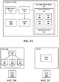
- FIG. 2A illustrates an example of peripheral device, according to one or more embodiments
- FIG. 2B illustrates an example of a battery, according to one or more embodiments
- FIG. 2C illustrates another example of an information handling system that includes a battery, according to one or more embodiments
- FIG. 3A illustrates an example of charging and discharging a battery of a peripheral device, according to one or more embodiments
- FIG. 3B illustrates an example of charging and discharging a battery, which includes a reserve, of a peripheral device, according to one or more embodiments
- FIG. 3C illustrates another example of charging and discharging a battery, which includes a reserve, of a peripheral device, according to one or more embodiments
- FIG. 4 illustrates an example of a method of utilizing a battery of a peripheral device, according to one or more embodiments
- FIG. 5 illustrates another example of a method of utilizing a battery of a system, according to one or more embodiments.
- FIG. 6 illustrates an example of a method of utilizing a battery, according to one or more embodiments.
- a reference numeral refers to a class or type of entity, and any letter following such reference numeral refers to a specific instance of a particular entity of that class or type.
- a hypothetical entity referenced by ‘ 12 A’ may refer to a particular instance of a particular class/type, and the reference ‘12’ may refer to a collection of instances belonging to that particular class/type or any one instance of that class/type in general.
- a user may have a need to rapidly charge a device (e.g., a peripheral device).
- the device may be charged ten to thirty seconds.
- the device may be utilized for about thirty minutes after it is charged ten to thirty seconds. In one or more embodiments, this may not be a normal mode of operation, but there may be instances where the user wants to utilize the device but discovers that there is no charge for utilization remaining in the device.
- a high capacity capacitor e.g., a “supercapacitor”, an “ultracapacitor”, etc.
- the high capacity capacitor may be charged before a battery of the device.
- the high capacity capacitor may be rapidly charged.
- the high capacity capacitor may be charged ten to thirty seconds and may provide power to the device for about thirty minutes after it is charged ten to thirty seconds.
- a high capacity capacitor may have a capacitance value much higher than other capacitors.
- a high capacity capacitor may have a capacitance per volume value much higher than other capacitors.
- a high capacity capacitor may have a volume of three United States quarter dollar value coins and may have a capacitance of one or more Farads.
- the high capacity capacitor may be charged more rapidly than a battery.
- a high capacity capacitor may not utilize a conventional solid dielectric.
- a high capacity capacitor may utilize an electrostatic double-layer capacitance and an electrochemical pseudocapacitance, which both may contribute to a total capacitance of the high capacity capacitor.
- a synthetic rapid charge capability of the device may be attained without losing a total time of normal utilization of the device.
- the total time of normal utilization of the device may be fifteen hours.
- increasing a volume of a battery of the device may provide total time of normal utilization of the device and the synthetic rapidly charge capability of the device.
- less volume total may be utilized by increasing a volume of a battery rather than not changing the volume of the battery and adding a high capacity capacitor.
- a volume of the battery may be increased by three percent (3%) to provide an additional thirty minutes of utilization of the device.
- an overall length of the stylus may be increased by three millimeters (3 mm) if a volume of the battery is increased to provide a rapid charge capability of the stylus, while the overall length of the stylus may be increased by thirty-five millimeters (35 mm) if a high capacity capacitor is utilized to provide a rapid charge capability of the stylus.
- it may be advantageous to increase a volume of a battery rather than adding a high capacity capacitor to a design based at least on one or more system, one or more methods, and/or one or more processes described herein.
- An information handling system (IHS) 110 may include a hardware resource or an aggregate of hardware resources operable to compute, classify, process, transmit, receive, retrieve, originate, switch, store, display, manifest, detect, record, reproduce, handle, and/or utilize various forms of information, intelligence, or data for business, scientific, control, entertainment, or other purposes, according to one or more embodiments.
- IHS 110 may be a personal computer, a desktop computer system, a laptop computer system, a server computer system, a mobile device, a tablet computing device, a personal digital assistant (PDA), a consumer electronic device, an electronic music player, an electronic camera, an electronic video player, a wireless access point, a network storage device, or another suitable device and may vary in size, shape, performance, functionality, and price.
- a portable IHS 110 may include or have a form factor of that of or similar to one or more of a laptop, a notebook, a telephone, a tablet, and a PDA, among others.
- a portable IHS 110 may be readily carried and/or transported by a user (e.g., a person).
- components of IHS 110 may include one or more storage devices, one or more communications ports for communicating with external devices as well as various input and output (I/O) devices, such as a keyboard, a mouse, and a video display, among others.
- IHS 110 may include one or more buses operable to transmit communication between or among two or more hardware components.
- a bus of IHS 110 may include one or more of a memory bus, a peripheral bus, and a local bus, among others.
- a bus of IHS 110 may include one or more of a Micro Channel Architecture (MCA) bus, an Industry Standard Architecture (ISA) bus, an Enhanced ISA (EISA) bus, a Peripheral Component Interconnect (PCI) bus, HyperTransport (HT) bus, an inter-integrated circuit (I 2 C) bus, a serial peripheral interface (SPI) bus, a low pin count (LPC) bus, an enhanced serial peripheral interface (eSPI) bus, a universal serial bus (USB), a system management bus (SMBus), and a Video Electronics Standards Association (VESA) local bus, among others.
- MCA Micro Channel Architecture
- ISA Industry Standard Architecture
- EISA Enhanced ISA
- PCI Peripheral Component Interconnect
- HT HyperTransport
- I 2 C inter-integrated circuit
- SPI serial peripheral interface
- LPC low pin count
- eSPI enhanced serial peripheral interface
- USB universal serial bus
- SMB system management bus
- VESA Video Electronics Standards Association
- IHS 110 may include firmware that controls and/or communicates with one or more hard drives, network circuitry, one or more memory devices, one or more I/O devices, and/or one or more other peripheral devices.
- firmware may include software embedded in an IHS component utilized to perform tasks.
- firmware may be stored in non-volatile memory, such as storage that does not lose stored data upon loss of power.
- firmware associated with an IHS component may be stored in non-volatile memory that is accessible to one or more IHS components.
- firmware associated with an IHS component may be stored in non-volatile memory that may be dedicated to and includes part of that component.
- an embedded controller may include firmware that may be stored via non-volatile memory that may be dedicated to and includes part of the embedded controller.
- IHS 110 may include a processor 120 , a volatile memory medium 150 , non-volatile memory media 160 and 170 , an I/O subsystem 175 , and a network interface 180 .
- volatile memory medium 150 , non-volatile memory media 160 and 170 , I/O subsystem 175 , and network interface 180 may be communicatively coupled to processor 120 .
- one or more of volatile memory medium 150 , non-volatile memory media 160 and 170 , I/O subsystem 175 , and network interface 180 may be communicatively coupled to processor 120 via one or more buses, one or more switches, and/or one or more root complexes, among others.
- one or more of volatile memory medium 150 , non-volatile memory media 160 and 170 , I/O subsystem 175 , and network interface 180 may be communicatively coupled to processor 120 via one or more PCI-Express (PCIe) root complexes.
- PCIe PCI-Express
- one or more of an I/O subsystem 175 and a network interface 180 may be communicatively coupled to processor 120 via one or more PCIe switches.
- the term “memory medium” may mean a “storage device”, a “memory”, a “memory device”, a “tangible computer readable storage medium”, and/or a “computer-readable medium”.
- computer-readable media may include, without limitation, storage media such as a direct access storage device (e.g., a hard disk drive, a floppy disk, etc.), a sequential access storage device (e.g., a tape disk drive), a compact disk (CD), a CD-ROM, a digital versatile disc (DVD), a random access memory (RAM), a read-only memory (ROM), a one-time programmable (OTP) memory, an electrically erasable programmable read-only memory (EEPROM), and/or a flash memory, a solid state drive (SSD), or any combination of the foregoing, among others.
- direct access storage device e.g., a hard disk drive, a floppy disk, etc.
- sequential access storage device e.g.
- one or more protocols may be utilized in transferring data to and/or from a memory medium.
- the one or more protocols may include one or more of small computer system interface (SCSI), Serial Attached SCSI (SAS) or another transport that operates with the SCSI protocol, advanced technology attachment (ATA), serial ATA (SATA), a USB interface, an Institute of Electrical and Electronics Engineers (IEEE) 1394 interface, a Thunderbolt interface, an advanced technology attachment packet interface (ATAPI), serial storage architecture (SSA), integrated drive electronics (IDE), or any combination thereof, among others.
- SCSI small computer system interface
- SAS Serial Attached SCSI
- ATA advanced technology attachment
- SATA serial ATA
- USB interface an Institute of Electrical and Electronics Engineers 1394 interface
- Thunderbolt interface an advanced technology attachment packet interface
- ATAPI advanced technology attachment packet interface
- SSA serial storage architecture
- IDE integrated drive electronics
- Volatile memory medium 150 may include volatile storage such as, for example, RAM, DRAM (dynamic RAM), EDO RAM (extended data out RAM), SRAM (static RAM), etc.
- One or more of non-volatile memory media 160 and 170 may include nonvolatile storage such as, for example, a read only memory (ROM), a programmable ROM (PROM), an erasable PROM (EPROM), an electrically erasable PROM, NVRAM (non-volatile RAM), ferroelectric RAM (FRAM), a magnetic medium (e.g., a hard drive, a floppy disk, a magnetic tape, etc.), optical storage (e.g., a CD, a DVD, a BLU-RAY disc, etc.), flash memory, a SSD, etc.
- a memory medium can include one or more volatile storages and/or one or more nonvolatile storages.
- network interface 180 may be utilized in communicating with one or more networks and/or one or more other information handling systems.
- network interface 180 may enable IHS 110 to communicate via a network utilizing a suitable transmission protocol and/or standard.
- network interface 180 may be coupled to a wired network.
- network interface 180 may be coupled to an optical network.
- network interface 180 may be coupled to a wireless network.
- network interface 180 may be communicatively coupled via a network to a network storage resource.
- the network may be implemented as, or may be a part of, a storage area network (SAN), personal area network (PAN), local area network (LAN), a metropolitan area network (MAN), a wide area network (WAN), a wireless local area network (WLAN), a virtual private network (VPN), an intranet, an Internet or another appropriate architecture or system that facilitates the communication of signals, data and/or messages (generally referred to as data).
- SAN storage area network
- PAN personal area network
- LAN local area network
- MAN metropolitan area network
- WAN wide area network
- WLAN wireless local area network
- VPN virtual private network
- intranet an Internet or another appropriate architecture or system that facilitates the communication of signals, data and/or messages (generally referred to as data).
- the network may transmit data utilizing a desired storage and/or communication protocol, including one or more of Fibre Channel, Frame Relay, Asynchronous Transfer Mode (ATM), Internet protocol (IP), other packet-based protocol, Internet SCSI (iSCSI), or any combination thereof, among others.
- a desired storage and/or communication protocol including one or more of Fibre Channel, Frame Relay, Asynchronous Transfer Mode (ATM), Internet protocol (IP), other packet-based protocol, Internet SCSI (iSCSI), or any combination thereof, among others.
- processor 120 may execute processor instructions in implementing one or more systems, one or more flowcharts, one or more methods, and/or one or more processes described herein. In one example, processor 120 may execute processor instructions from one or more of memory media 150 , 160 , and 170 in implementing one or more systems, one or more flowcharts, one or more methods, and/or one or more processes described herein. In another example, processor 120 may execute processor instructions via network interface 180 in implementing one or more systems, one or more flowcharts, one or more methods, and/or one or more processes described herein.
- processor 120 may include one or more of a system, a device, and an apparatus operable to interpret and/or execute program instructions and/or process data, among others, and may include one or more of a microprocessor, a microcontroller, a digital signal processor (DSP), an application specific integrated circuit (ASIC), and another digital or analog circuitry configured to interpret and/or execute program instructions and/or process data, among others.
- processor 120 may interpret and/or execute program instructions and/or process data stored locally (e.g., via memory media 150 , 160 , and 170 and/or another component of IHS 110 ).
- processor 120 may interpret and/or execute program instructions and/or process data stored remotely (e.g., via a network storage resource).
- I/O subsystem 175 may represent a variety of communication interfaces, graphics interfaces, video interfaces, user input interfaces, and/or peripheral interfaces, among others.
- PO subsystem 175 may include one or more of a touch panel and a display adapter, among others.
- a touch panel may include circuitry that enables touch functionality in conjunction with a display that is driven by a display adapter.
- non-volatile memory medium 160 may include an operating system (OS) 162 , and applications (APPs) 164 - 168 .
- OS 162 and APPs 164 - 168 may include processor instructions executable by processor 120 .
- processor 120 may execute processor instructions of one or more of OS 162 and APPs 164 - 168 via non-volatile memory medium 160 .
- one or more portions of the processor instructions of the one or more of OS 162 and APPs 164 - 168 may be transferred to volatile memory medium 150 , and processor 120 may execute the one or more portions of the processor instructions of the one or more of OS 162 and APPs 164 - 168 via volatile memory medium 150 .
- non-volatile memory medium 170 may include information handling system firmware (IHSFW) 172 .
- IHSFW 172 may include processor instructions executable by processor 120 .
- IHSFW 172 may include one or more structures and/or one or more functionalities of and/or compliant with one or more of a basic input/output system (BIOS), an Extensible Firmware Interface (EFI), a Unified Extensible Firmware Interface (UEFI), and an Advanced Configuration and Power Interface (ACPI), among others.
- BIOS basic input/output system
- EFI Extensible Firmware Interface
- UEFI Unified Extensible Firmware Interface
- ACPI Advanced Configuration and Power Interface
- processor 120 may execute processor instructions of IHSFW 172 via non-volatile memory medium 170 .
- one or more portions of the processor instructions of IHSFW 172 may be transferred to volatile memory medium 150 , and processor 120 may execute the one or more portions of the processor instructions of IHSFW 172 via volatile memory medium 150 .
- processor 120 and one or more components of IHS 110 may be included in a system-on-chip (SoC).
- SoC may include processor 120 and a platform controller hub (not specifically illustrated).
- a peripheral device 190 may be coupled to IHS 110 in a wireless fashion.
- peripheral device 190 may be a mouse.
- peripheral device 190 may be a touchpad.
- peripheral device 190 may be a stylus.
- peripheral device 190 may wirelessly communicate the peripheral data with IHS 110 .
- peripheral device 190 may wirelessly communicate the peripheral data with IHS 110 via one or more wireless protocols.
- peripheral device 190 may wirelessly communicate the peripheral data with IHS 110 via one or more of an IEEE 802.11 protocol, an IEEE 802.15 protocol, a Bluetooth protocol, a ZigBee protocol, and a 6LoWPAN protocol, among others.
- the peripheral data may include information indicating a mouse movement, a mouse click, a stylus movement, a stylus click, electronic accelerometer data, electronic gyroscope data, a touchpad drag, a touchpad click, etc.
- peripheral device 190 may include a processor 220 , a volatile memory medium 250 , a non-volatile memory medium 270 , and an interface 280 .
- non-volatile memory medium 270 may include a peripheral device firmware (FW) 273 , which may include an OS 262 and APPs 264 - 268 , and may include peripheral device data 277 .
- OS 262 may be or include a real-time operating system (RTOS).
- RTOS real-time operating system
- OS 262 may be or include a portable operating system interface (POSIX) compliant operating system.
- interface 280 may include circuitry that enables communicatively coupling to one or more devices.
- interface 280 may include circuitry that enables communicatively coupling to one or more buses.
- the one or more buses may include one or more buses described herein, among others.
- interface 280 may include circuitry that enables one or more interrupt signals to be received.
- interface 280 may include general purpose input/output (GPIO) circuitry, and the GPIO circuitry may enable one or more interrupt signals to be received and/or provided via at least one interrupt line.
- GPIO general purpose input/output
- interface 280 may include GPIO circuitry that may enable peripheral device 190 to provide and/or receive signals associated with other circuitry (e.g., diagnostic circuitry, etc.).
- interface 280 may include circuitry that enables communicatively coupling to one or more networks.
- interface 280 may include circuitry that enables communicatively coupling to network interface 180 .
- interface 280 may include a network interface.
- interface 280 may include wireless communication circuitry.
- the wireless communication circuitry may enable peripheral device to wirelessly communicate with an information handling system (e.g., IHS 110 ).
- interface 280 may include a charging interface.
- the charging interface may receive electrical current at a voltage.
- the charging interface may include a wired charging interface.
- the charging interface may include a wireless charging interface.
- one or more of OS 262 and APPs 264 - 268 may include processor instructions executable by processor 220 .
- processor 220 may execute processor instructions of one or more of OS 262 and APPs 264 - 268 via non-volatile memory medium 270 .
- one or more portions of the processor instructions of the one or more of OS 262 and APPs 264 - 268 may be transferred to volatile memory medium 250 , and processor 220 may execute the one or more portions of the processor instructions of the one or more of OS 262 and APPs 264 - 268 via volatile memory medium 250 .
- processor 220 may execute instructions in accordance with at least a portion of one or more systems, one or more flowcharts, one or more methods, and/or one or more processes described herein.
- non-volatile memory medium 270 and/or volatile memory medium 250 may store instructions that may be executable in accordance with at least a portion of one or more systems, flowcharts, one or more methods, and/or one or more processes described herein.
- processor 220 may execute instructions in accordance with at least a portion of one or more of systems, flowcharts, methods, and/or processes described herein.
- non-volatile memory medium 270 and/or volatile memory medium 250 may store instructions that may be executable in accordance with at least a portion of one or more of systems, flowcharts, methods, and/or processes described herein.
- processor 220 may utilize peripheral device data 277 .
- processor 220 may utilize peripheral device data 277 via non-volatile memory medium 270 .
- one or more portions of peripheral device data 277 may be transferred to volatile memory medium 250 , and processor 220 may utilize peripheral device data 277 via volatile memory medium 250 .
- peripheral device 190 may include a battery 285 A.
- battery 285 A may provide power to components of peripheral device 190 .
- battery 285 A may provide power one or more of processor 220 , volatile memory medium 250 , non-volatile memory medium 270 , and interface 280 , among others.
- a battery 285 may include circuitry 286 .
- battery 285 may be or include a battery system.
- circuitry 286 may include a battery management unit (BMU).
- circuitry 286 may include a processor.
- circuitry 286 may include a memory medium that stores instructions executable by the processor of circuitry 286 .
- circuitry 286 may include a microcontroller.
- circuitry 286 may be configured to implement at least a portion of one or more systems, one or more flowcharts, one or more methods, and/or one or more processes described herein.
- the processor of circuitry 286 may execute processor instructions in accordance with at least a portion of one or more systems, one or more flowcharts, one or more methods, and/or one or more processes described herein.
- battery 285 may include cells 288 A- 288 C.
- a cell 288 may include a lithium-ion (Li-ion) cell.
- cells 288 A- 288 C may be coupled to one another.
- cells 288 A- 288 C may be coupled to one another to provide a current greater than a single cells 288 may provide.
- cells 288 A- 288 C may be coupled to one another to provide a voltage greater than a single cells 288 may provide.
- battery 285 is illustrated with multiple cells 288 , battery 285 may include a single cell 288 , according to one or more embodiments.
- circuitry 286 may be coupled to cells 288 . In one or more embodiments, circuitry 286 may determine a voltage associated with a cell 288 . In one or more embodiments, circuitry 286 may determine a charging current associated with a cell 288 . In one or more embodiments, circuitry 286 may determine a discharging current associated with a cell 288 .
- circuitry 286 may regulate one or more egresses of power from one or more of cells 288 A- 288 C. For example, circuitry 286 may regulate power transferred from one or more of cells 288 A- 288 C to one or more components of peripheral device 190 . In one or more embodiments, circuitry 286 may regulate one or more ingresses of power to one or more of cells 288 A- 288 C. For example, circuitry 286 may regulate power transferred to one or more of cells 288 A- 288 C from a power source 290 A. For instance, power source 290 A may be configured to provide power to battery 285 to charge battery 285 .
- battery 285 may be coupled to power source 290 A. In one example, battery 285 may be coupled to power source 290 A in a wired fashion. In another example, battery 285 may be coupled to power source 290 A in a wireless fashion. In one or more embodiments, battery 285 may be charged by power source 290 A. In one or more embodiments, battery 285 may not include circuitry 286 . For example, battery 285 may include one or more cells 288 without circuitry 286 .
- IHS 110 may include a battery 285 B.
- battery 285 B may provide power to one or more components of IHS 110 .
- battery 285 B may provide power to one or more of processor 120 , volatile memory medium 150 , non-volatile memory medium 160 , non-volatile memory medium 170 , PO subsystem 175 , and network interface 175 , among others.
- battery 285 B may provide power to peripheral device 190 .
- battery 285 B may provide power to peripheral device 190 .
- battery 285 B may charge battery 285 A.
- IHS 110 may be coupled to power source 290 B. In one example, IHS 110 may be coupled to power source 290 B in a wired fashion. In another example, IHS 110 may be coupled to power source 290 B in a wireless fashion. In one or more embodiments, battery 285 B may be charged by power source 290 B.
- battery 285 may store a charge with a voltage 310 .
- voltage 310 may be a first end of discharge voltage.
- the first end of discharge voltage may be a first minimum voltage cutoff.
- peripheral device 190 may not discharge battery 285 below voltage 310 .
- circuitry 286 may not discharge battery 285 below voltage 310 .
- preventing a voltage of battery 285 from dropping below the first end of discharge voltage may prevent a degradation of a cell 288 of battery 285 .
- preventing a voltage of battery 285 from dropping below the first end of discharge voltage may prevent damage to a cell 288 of battery 285 .
- battery 285 may be charged to a voltage 312 during a period of time 320 A. In one or more embodiments, battery 285 may be charged to voltage 312 via power source 290 . As illustrated, battery 285 may be discharged to voltage 310 during a period of time 330 A. In one or more embodiments, utilizing peripheral device 190 may discharge battery 285 . As shown, battery 285 may be charged to voltage 312 during a period of time 320 B. As illustrated, battery 285 may be discharged to voltage 310 during a period of time 330 B. As shown, battery 285 may be charged to voltage 312 during a period of time 320 C. As illustrated, battery 285 may be discharged to voltage 310 during a period of time 330 C.
- battery 285 may be configured with an energy reserve.
- battery 285 may be configured with bigger one or more cells that may provide the energy reserve.
- the energy reserve may permit a second end of discharge voltage that is higher than the first end of discharge voltage.
- the second end of discharge voltage may be voltage 314 .
- voltage 314 may be higher than voltage 310 .
- peripheral device 190 may be utilized which may discharge battery 285 to voltage 314 . When battery 285 is discharged to voltage 314 , peripheral device 190 may indicate that battery 285 is out of charge, according to one or more embodiments.
- battery 285 may be charged to voltage 312 during period of time 320 A. As illustrated, battery 285 may be discharged to voltage 314 during period of time 330 A.
- peripheral device 190 may indicate that it is out of charge. In one or more embodiments, after period of time 330 A, peripheral device 190 may indicate that it needs to be charged. In one or more embodiments, after period of time 330 A, peripheral device 190 may no longer function as a peripheral device. In one or more embodiments, peripheral device 190 may be charged.
- battery 285 may be charged to voltage 316 during a period of time 322 .
- charging battery 285 during period of time 322 may permit access to the energy reserve of battery 285 .
- battery 285 may be discharged to voltage 310 during period of time 332 .
- battery 285 may be discharged to the first end of discharge voltage during period of time 332 .
- battery 285 may be charged to voltage 312 during period of time 320 B.
- battery 285 may be discharged to voltage 314 during period of time 330 B.
- a third end of discharge voltage may be utilized.
- the third end of discharge voltage may be between the first end of discharge voltage and the second end of discharge voltage.
- the third end of discharge voltage may be a voltage 318 , which may be between voltage 310 and voltage 314 .
- battery 285 may be charged to voltage 312 during period of time 320 A. As illustrated, battery 285 may be discharged to voltage 314 during period of time 330 A.
- peripheral device 190 may indicate that it is out of charge. In one or more embodiments, after period of time 330 A, peripheral device 190 may indicate that it needs to be charged. In one or more embodiments, after period of time 330 A, peripheral device 190 may no longer function as a peripheral device. In one or more embodiments, peripheral device 190 may be charged.
- battery 285 may be charged to voltage 316 during a period of time 322 A. In one or more embodiments, charging battery 285 during period of time 322 A may permit access to the energy reserve of battery 285 . As illustrated, battery 285 may be discharged to a voltage 318 during a period of time 334 A. For example, battery 285 may be discharged to the third end of discharge voltage during period of time 334 A.
- peripheral device 190 may indicate that it is out of charge. In one or more embodiments, after period of time 334 A, peripheral device 190 may indicate that it needs to be charged. In one or more embodiments, after period of time 334 A, peripheral device 190 may no longer function as a peripheral device. In one or more embodiments, peripheral device 190 may be charged.
- battery 285 may be charged to voltage 314 during a period of time 322 B. In one or more embodiments, charging battery 285 during period of time 322 B may permit access to the energy reserve of battery 285 . As illustrated, battery 285 may be discharged to voltage 310 during a period of time 334 B. For example, battery 285 may be discharged to the third end of discharge voltage during period of time 334 B. As illustrated, battery 285 may be charged to voltage 312 during period of time 324 . As shown, battery 285 may be discharged to voltage 314 during period of time 330 B.
- FIGS. 3A-3C are described with reference to peripheral device 190 , any system may be utilized in place of peripheral device 190 in the descriptions associated with FIGS. 3A-3C , according to one or more embodiments.
- IHS 110 may be utilized in place of peripheral device 190 in the descriptions associated with FIGS. 3A-3C .
- a battery of a system may be charged to a full capacity or above a first threshold capacity.
- the system may be or include peripheral device 190 .
- the battery of the system may be battery 285 A.
- the system may be or include IHS 110 .
- the battery of the system may be battery 285 B.
- the battery of the system may be discharged under normal utilization.
- the battery may be discharged normally.
- the battery may be discharged during normal utilization of the system.
- the battery of the system may be charged. In one example, the battery of the system may be charged in a wired fashion. In another example, the battery of the system may be charged in a wireless fashion.
- the battery of the system may be discharged utilizing the reserved energy capacity.
- a battery may be charged from a first end of discharge voltage to a first voltage.
- battery 285 may be charged from voltage 310 to voltage 312 .
- the battery may be discharged to a second end of discharge voltage, greater than the first end of discharge voltage.
- battery 285 may be discharged to voltage 314 .
- the system may be or include peripheral device 190 .
- discharging battery 285 A may include providing power from battery 285 A to one or more components of peripheral device 190 .
- discharging battery 285 A may include providing power from battery 285 A to one or more of processor 220 , volatile memory medium 250 , non-volatile memory medium 270 , and interface 280 , among others, of peripheral device 190 .
- the system may be or include IHS 110 .
- discharging battery 285 B may include providing power from battery 285 B to one or more components of IHS 110 .
- discharging battery 285 B may include providing power from battery 285 B to one or more of processor 120 , volatile memory medium 150 , non-volatile memory medium 160 , non-volatile memory medium 170 , I/O subsystem 175 , and network interface 175 , among others, of IHS 110 .
- the system may be a wireless system.
- the wireless system may include a wireless interface coupled to the battery and configured to wirelessly communicate peripheral data with an information handling system.
- ceasing at least one function of the system may be performed in response to discharging the battery to the second end of discharge voltage.
- the battery may be charged from the second end of discharge voltage to a second voltage, greater than the second end of discharge voltage and less than the first voltage.
- battery 285 may be charged from voltage may be charged to voltage 316 .
- the battery may be discharged to a third end of discharge voltage, less than the second end of discharge voltage and greater than the first end of discharge voltage.
- battery 285 may be discharged to voltage 318 .
- the at least one function of the system may be ceased. In one or more embodiments, the at least one function of the system may be ceased in response to discharging the battery to the third end of discharge voltage.
- the battery may be charged from the third end of discharge voltage to a third voltage, greater than or equal to the second end of discharge voltage.
- battery 285 may be charged from voltage 318 to voltage 314 . In another example, battery 285 may be charged from voltage 318 to a voltage greater than voltage 314 .
- the battery may be discharged to the first end of discharge voltage. For example, battery 285 may be discharged to voltage 310 .
- the battery may include a battery management unit.
- the battery management unit may measure a first present voltage.
- the first present voltage may be a voltage of battery 285 at a first time when the battery management unit measures the voltage of battery 285 .
- the battery management unit may include an analog to digital converter (ADC), which may convert a voltage of battery 285 into digital values that may be utilized by the battery management unit.
- ADC may measure the first present voltage.
- the battery management unit may determine that the first present voltage is the second end of discharge voltage or the third end of discharge voltage.
- the battery management unit may cease providing power to the system.
- the battery management unit may cease providing power to the system in response to determining that the first present voltage is the second end of discharge voltage or the third end of discharge voltage.
- the first present voltage may be the second end of discharge voltage.
- the battery management unit may measure a second present voltage of the battery.
- the second present voltage may be a voltage of battery 285 at a second time, after the first time, when the battery management unit measures the voltage of battery 285 .
- the ADC may measure the second present voltage of the battery.
- the battery management unit may determine that the second present voltage is the second voltage.
- the battery management unit may permit the battery to provide power to the system.
- the battery management unit may permit the battery to provide power to the system in response to determining that the second present voltage is the second voltage.
- the battery may include one or more lithium-ion cells.
- the battery may include circuitry that may measure a first present voltage of the one or more lithium-ion cells.
- the circuitry may include an ADC.
- the ADC may measure a first present voltage of the one or more lithium-ion cells.
- the first present voltage may be a voltage of the one or more lithium-ion cells at a first time when the circuitry measures the voltage of the one or more lithium-ion cells.
- the circuitry may determine that the first present voltage is the first end of discharge voltage. For example, the circuitry may withhold power from the one or more lithium-ion cells to the system to prevent damage to the one or more lithium-ion cells. For instance, the circuitry may withhold power from the one or more lithium-ion cells in response to determining that the first present voltage is the first end of discharge voltage. In one or more embodiments, the circuitry may include a battery management unit.
- a present voltage of the battery is the second end of discharge voltage.
- the system may indicate that the system needs to be coupled to a power source.
- the system may indicate that the system needs to be coupled to a power source in response to determining that the present voltage of the battery is the second end of discharge voltage.
- indicating that the system needs to be coupled to a power source may include emitting light emissions and/or providing at least one sound.
- emitting light emissions may include displaying information via a display.
- emitting light emissions may include illuminating a light emitting diode (LED).
- a battery may be charged from a first end of discharge voltage to a first voltage.
- battery 285 may be charged from voltage 310 to voltage 312 .
- circuitry 286 may be configured to charge battery 285 from a first end of discharge voltage to a first voltage.
- the battery may include one or more cells (e.g., one or more of cells 288 A- 288 C).
- the one or more cells may be charged from a first end of discharge voltage to a first voltage.
- circuitry 286 may be configured to charge the one or more cells from a first end of discharge voltage to a first voltage.
- battery 285 may be charged via power source 290 .
- the one or more cells e.g., one or more of cells 288 A- 288 C
- the battery may be discharged to a second end of discharge voltage, greater than the first end of discharge voltage.
- battery 285 may be discharged to voltage 314 .
- circuitry 286 may be further configured to discharge the battery to a second end of discharge voltage.
- circuitry 286 may be further configured to discharge battery 285 to a second end of discharge voltage.
- circuitry 286 may be further configured to discharge the one or more cells to a second end of discharge voltage.
- discharging battery 285 may include providing power from battery 285 to one or more components of peripheral device 190 .
- discharging battery 285 may include providing power from battery 285 to one or more of processor 220 , volatile memory medium 250 , non-volatile memory medium 270 , and interface 280 , among others, of peripheral device 190 .
- power from the one or more cells to at least one component of a system may be withheld.
- the system may be or include at least one of an information handling system and a peripheral device.
- circuitry 286 may be further configured to withhold power from the one or more cells to at least one component of a system. In one instance, circuitry 286 may be further configured to withhold power from the one or more cells to at least one of processor 220 , volatile memory medium 250 , non-volatile memory medium 270 , and interface 280 , among others, of peripheral device 190 . In another instance, circuitry 286 may be further configured to withhold power from the one or more cells to at least one of processor 120 , volatile memory medium 150 , non-volatile memory medium 160 , non-volatile memory medium 170 , I/O subsystem 175 , and network interface 175 , among others, of IHS 110 . In one or more embodiments, circuitry 286 may be further configured to withhold power from the one or more cells to at least one component of a system in response to discharging the battery to the second end of discharge voltage.
- the battery may be charged from the second end of discharge voltage to a second voltage, greater than the second end of discharge voltage and less than the first voltage.
- battery 285 may be charged from voltage may be charged to voltage 316 .
- circuitry 286 may be further configured to charge battery 286 , from the second end of discharge voltage to a second voltage, greater than the second end of discharge voltage and less than the first voltage.
- circuitry 286 may be further configured to charge the one or more cells from the second end of discharge voltage to a second voltage, greater than the second end of discharge voltage and less than the first voltage.
- circuitry 286 may be further configured to charge the one or more cells to voltage 316 .
- the battery may be discharged to a third end of discharge voltage, less than the second end of discharge voltage and greater than the first end of discharge voltage.
- battery 285 may be discharged to voltage 318 .
- circuitry 286 may be further configured to discharge battery 285 to a third end of discharge voltage.
- circuitry 286 may be further configured to discharge the one or more cells to a third end of discharge voltage.
- circuitry 286 may be further configured to discharge the one or more cells to voltage 318 .
- circuitry 286 may be further configured to withhold power from the one or more cells to the at least one component of the system. In one or more embodiments, circuitry 286 may be further configured to withhold power from the one or more cells to the at least one component of the system in response to discharging the battery to the third end of discharge voltage.
- the battery may be charged from the third end of discharge voltage to a third voltage, greater than or equal to the second end of discharge voltage.
- battery 285 may be charged from voltage 318 to voltage 314 .
- battery 285 may be charged from voltage 318 to a voltage greater than voltage 314 .
- circuitry 286 may be further configured to charge battery 285 from the third end of discharge voltage to a third voltage, greater than or equal to the second end of discharge voltage.
- circuitry 286 may be further configured to charge the one or more cells from the third end of discharge voltage to a third voltage, greater than or equal to the second end of discharge voltage.
- the battery may be discharged to the first end of discharge voltage.
- battery 285 may be discharged to voltage 310 .
- circuitry 286 may be further configured to discharge battery 285 to the first end of discharge voltage.
- circuitry 286 may be further configured to discharge the one or more cells to the first end of discharge voltage.
- circuitry 286 may include a battery management unit.
- the battery management unit may be configured to: measure a first present voltage; determine that the first present voltage is the second end of discharge voltage or the third end of discharge voltage; and in response to determining that the first present voltage is the second end of discharge voltage or the third end of discharge voltage, withhold power from the one or more cells to the at least one component of the system.
- circuitry 286 may include an ADC.
- the ADC may convert a voltage of battery 285 or a voltage of a cell of battery 285 into digital values that may be utilized by the battery management unit or by the circuitry.
- the ADC may measure a first present voltage.
- the one or more cells may include respective one or more lithium-ion cells.
- circuitry 286 may be further configured to: measure a first present voltage of the one or more; determine that the first present voltage is the first end of discharge voltage; and withhold power from the one or more lithium-ion cells to the at least one component of the system to prevent damage to the one or more lithium-ion cells.
- circuitry 286 may be further configured to: determine that a present voltage of the battery is the second end of discharge voltage; and in response to determining that the present voltage of the battery is the second end of discharge voltage, indicate that the system needs to be coupled to a power source.
- indicating that the system needs to be coupled to a power source may include emitting light emissions and/or providing at least one sound. In one example, emitting light emissions may include displaying information via a display. In another example, emitting light emissions may include illuminating a LED. In one or more embodiments, indicating that the system needs to be coupled to a power source may include providing information to a processor, which indicates that the system needs to be coupled to a power source. In one example, indicating that the system needs to be coupled to a power source may include providing information to processor 220 , which indicates that the peripheral device needs to be coupled to a power source. In another example, indicating that the system needs to be coupled to a power source may include providing information to processor 120 , which indicates that the system needs to be coupled to a power source.
- access of the reserve energy of a battery may be provided to a system via one or more switches.
- a switch may be actuated.
- access of the reserve energy of the battery may be provided to the system in response to determining that the switch was actuated.
- a combination of switches may be actuated.
- access of the reserve energy of the battery may be provided to the system in response to determining that the combination of switches was actuated.
- access of the reserve energy of a battery may be provided to a system via instructions executable by a processor.
- the instructions executable by the processor may provide access of the reserve energy of the battery to the system.
- one or more of the method and/or process elements and/or one or more portions of a method and/or a process element may be performed in varying orders, may be repeated, or may be omitted.
- additional, supplementary, and/or duplicated method and/or process elements may be implemented, instantiated, and/or performed as desired, according to one or more embodiments.
- one or more of system elements may be omitted and/or additional system elements may be added as desired, according to one or more embodiments.
- a memory medium may be and/or may include an article of manufacture.
- the article of manufacture may include and/or may be a software product and/or a program product.
- the memory medium may be coded and/or encoded with processor-executable instructions in accordance with one or more flowcharts, one or more systems, one or more methods, and/or one or more processes described herein to produce the article of manufacture.
Landscapes
- Engineering & Computer Science (AREA)
- Power Engineering (AREA)
- Charge And Discharge Circuits For Batteries Or The Like (AREA)
Abstract
Description
Claims (20)
Priority Applications (1)
| Application Number | Priority Date | Filing Date | Title |
|---|---|---|---|
| US16/776,832 US11196279B2 (en) | 2020-01-30 | 2020-01-30 | System and method of utilizing a battery |
Applications Claiming Priority (1)
| Application Number | Priority Date | Filing Date | Title |
|---|---|---|---|
| US16/776,832 US11196279B2 (en) | 2020-01-30 | 2020-01-30 | System and method of utilizing a battery |
Publications (2)
| Publication Number | Publication Date |
|---|---|
| US20210242688A1 US20210242688A1 (en) | 2021-08-05 |
| US11196279B2 true US11196279B2 (en) | 2021-12-07 |
Family
ID=77062236
Family Applications (1)
| Application Number | Title | Priority Date | Filing Date |
|---|---|---|---|
| US16/776,832 Active 2040-08-06 US11196279B2 (en) | 2020-01-30 | 2020-01-30 | System and method of utilizing a battery |
Country Status (1)
| Country | Link |
|---|---|
| US (1) | US11196279B2 (en) |
Citations (2)
| Publication number | Priority date | Publication date | Assignee | Title |
|---|---|---|---|---|
| US20160190827A1 (en) * | 2013-09-19 | 2016-06-30 | Kabushiki Kaisha Toshiba | Charging device and method for the same, and discharging device and method for the same |
| US9694704B2 (en) * | 2012-02-02 | 2017-07-04 | Mitsubishi Heavy Industries, Ltd. | Electrical charging/discharging controller, charging control method, discharging control method, and program |
-
2020
- 2020-01-30 US US16/776,832 patent/US11196279B2/en active Active
Patent Citations (2)
| Publication number | Priority date | Publication date | Assignee | Title |
|---|---|---|---|---|
| US9694704B2 (en) * | 2012-02-02 | 2017-07-04 | Mitsubishi Heavy Industries, Ltd. | Electrical charging/discharging controller, charging control method, discharging control method, and program |
| US20160190827A1 (en) * | 2013-09-19 | 2016-06-30 | Kabushiki Kaisha Toshiba | Charging device and method for the same, and discharging device and method for the same |
Also Published As
| Publication number | Publication date |
|---|---|
| US20210242688A1 (en) | 2021-08-05 |
Similar Documents
| Publication | Publication Date | Title |
|---|---|---|
| US10305314B2 (en) | System and method of wirelessly charging devices | |
| US20230376099A1 (en) | System and method for dynamic switching between batteries in a dual battery system | |
| US20210116984A1 (en) | System and method for stepwise enablement of a cache memory in an information handling system | |
| US11829216B2 (en) | System and method of enhancing performances of information handling systems by utilizing graphics processing units | |
| US11809298B2 (en) | System and method of grouping information handling systems for software updates | |
| US11196279B2 (en) | System and method of utilizing a battery | |
| US11088407B2 (en) | System and method of managing battery cells | |
| US11294438B2 (en) | System and method of providing power from one portion of an information handling system to another portion of the information handling system | |
| US11670809B2 (en) | System and method of charging a rechargeable battery | |
| US11507507B2 (en) | System and method of backing up data from a volatile memory medium to a non-volatile memory medium | |
| US11302971B1 (en) | System and method of utilizing a rechargeable battery with an information handling system | |
| US10739840B2 (en) | System and method of utilizing operating context information | |
| US10482014B2 (en) | System and method of managing a memory medium | |
| US11757138B2 (en) | System and method of operating mobile information handling systems with rechargeable batteries | |
| US10877551B2 (en) | System and method of managing information handling systems | |
| US20200042063A1 (en) | System and Method of Utilizing Information Handling Systems with Multiple Power Levels | |
| US12292779B2 (en) | Systems and methods for battery context-aware limiting of bios managed operations | |
| US11394316B2 (en) | System and method of utilizing LLC converters | |
| US11822415B1 (en) | System and method of operating a power system of an information handling system | |
| US10996727B2 (en) | System and method of managing power in information handling system | |
| US12413086B2 (en) | Adjusting a charging rate of a battery of an information handling system | |
| US10621135B2 (en) | System and method of managing signals in information handling systems | |
| US12259436B2 (en) | Battery status monitoring and battery management of an information handling system | |
| US11789511B2 (en) | System and method of determining an issue associated with a power distribution system of an information handling system | |
| US10794958B2 (en) | System and method of determining battery system condition |
Legal Events
| Date | Code | Title | Description |
|---|---|---|---|
| AS | Assignment |
Owner name: DELL PRODUCTS L.P., TEXAS Free format text: ASSIGNMENT OF ASSIGNORS INTEREST;ASSIGNORS:KRISHNAKUMAR, KARTHIKEYAN;THOMPSON, RICHARD CHRISTOPHER;REEL/FRAME:051671/0074 Effective date: 20200127 |
|
| FEPP | Fee payment procedure |
Free format text: ENTITY STATUS SET TO UNDISCOUNTED (ORIGINAL EVENT CODE: BIG.); ENTITY STATUS OF PATENT OWNER: LARGE ENTITY |
|
| AS | Assignment |
Owner name: THE BANK OF NEW YORK MELLON TRUST COMPANY, N.A., AS COLLATERAL AGENT, TEXAS Free format text: PATENT SECURITY AGREEMENT (NOTES);ASSIGNORS:DELL PRODUCTS L.P.;EMC IP HOLDING COMPANY LLC;REEL/FRAME:052216/0758 Effective date: 20200324 |
|
| AS | Assignment |
Owner name: CREDIT SUISSE AG, CAYMAN ISLANDS BRANCH, NORTH CAROLINA Free format text: SECURITY AGREEMENT;ASSIGNORS:DELL PRODUCTS L.P.;EMC IP HOLDING COMPANY LLC;REEL/FRAME:052243/0773 Effective date: 20200326 |
|
| AS | Assignment |
Owner name: THE BANK OF NEW YORK MELLON TRUST COMPANY, N.A., TEXAS Free format text: SECURITY AGREEMENT;ASSIGNORS:CREDANT TECHNOLOGIES INC.;DELL INTERNATIONAL L.L.C.;DELL MARKETING L.P.;AND OTHERS;REEL/FRAME:053546/0001 Effective date: 20200409 |
|
| AS | Assignment |
Owner name: THE BANK OF NEW YORK MELLON TRUST COMPANY, N.A., AS COLLATERAL AGENT, TEXAS Free format text: SECURITY INTEREST;ASSIGNORS:DELL PRODUCTS L.P.;EMC CORPORATION;EMC IP HOLDING COMPANY LLC;REEL/FRAME:053311/0169 Effective date: 20200603 |
|
| STPP | Information on status: patent application and granting procedure in general |
Free format text: DOCKETED NEW CASE - READY FOR EXAMINATION |
|
| STPP | Information on status: patent application and granting procedure in general |
Free format text: NOTICE OF ALLOWANCE MAILED -- APPLICATION RECEIVED IN OFFICE OF PUBLICATIONS |
|
| AS | Assignment |
Owner name: EMC IP HOLDING COMPANY LLC, TEXAS Free format text: RELEASE OF SECURITY INTEREST AF REEL 052243 FRAME 0773;ASSIGNOR:CREDIT SUISSE AG, CAYMAN ISLANDS BRANCH;REEL/FRAME:058001/0152 Effective date: 20211101 Owner name: DELL PRODUCTS L.P., TEXAS Free format text: RELEASE OF SECURITY INTEREST AF REEL 052243 FRAME 0773;ASSIGNOR:CREDIT SUISSE AG, CAYMAN ISLANDS BRANCH;REEL/FRAME:058001/0152 Effective date: 20211101 |
|
| STPP | Information on status: patent application and granting procedure in general |
Free format text: PUBLICATIONS -- ISSUE FEE PAYMENT VERIFIED |
|
| STCF | Information on status: patent grant |
Free format text: PATENTED CASE |
|
| AS | Assignment |
Owner name: EMC IP HOLDING COMPANY LLC, TEXAS Free format text: RELEASE OF SECURITY INTEREST IN PATENTS PREVIOUSLY RECORDED AT REEL/FRAME (053311/0169);ASSIGNOR:THE BANK OF NEW YORK MELLON TRUST COMPANY, N.A., AS NOTES COLLATERAL AGENT;REEL/FRAME:060438/0742 Effective date: 20220329 Owner name: EMC CORPORATION, MASSACHUSETTS Free format text: RELEASE OF SECURITY INTEREST IN PATENTS PREVIOUSLY RECORDED AT REEL/FRAME (053311/0169);ASSIGNOR:THE BANK OF NEW YORK MELLON TRUST COMPANY, N.A., AS NOTES COLLATERAL AGENT;REEL/FRAME:060438/0742 Effective date: 20220329 Owner name: DELL PRODUCTS L.P., TEXAS Free format text: RELEASE OF SECURITY INTEREST IN PATENTS PREVIOUSLY RECORDED AT REEL/FRAME (053311/0169);ASSIGNOR:THE BANK OF NEW YORK MELLON TRUST COMPANY, N.A., AS NOTES COLLATERAL AGENT;REEL/FRAME:060438/0742 Effective date: 20220329 Owner name: EMC IP HOLDING COMPANY LLC, TEXAS Free format text: RELEASE OF SECURITY INTEREST IN PATENTS PREVIOUSLY RECORDED AT REEL/FRAME (052216/0758);ASSIGNOR:THE BANK OF NEW YORK MELLON TRUST COMPANY, N.A., AS NOTES COLLATERAL AGENT;REEL/FRAME:060438/0680 Effective date: 20220329 Owner name: DELL PRODUCTS L.P., TEXAS Free format text: RELEASE OF SECURITY INTEREST IN PATENTS PREVIOUSLY RECORDED AT REEL/FRAME (052216/0758);ASSIGNOR:THE BANK OF NEW YORK MELLON TRUST COMPANY, N.A., AS NOTES COLLATERAL AGENT;REEL/FRAME:060438/0680 Effective date: 20220329 Owner name: DELL MARKETING L.P. (ON BEHALF OF ITSELF AND AS SUCCESSOR-IN-INTEREST TO CREDANT TECHNOLOGIES, INC.), TEXAS Free format text: RELEASE OF SECURITY INTEREST IN PATENTS PREVIOUSLY RECORDED AT REEL/FRAME (053546/0001);ASSIGNOR:THE BANK OF NEW YORK MELLON TRUST COMPANY, N.A., AS NOTES COLLATERAL AGENT;REEL/FRAME:071642/0001 Effective date: 20220329 Owner name: DELL INTERNATIONAL L.L.C., TEXAS Free format text: RELEASE OF SECURITY INTEREST IN PATENTS PREVIOUSLY RECORDED AT REEL/FRAME (053546/0001);ASSIGNOR:THE BANK OF NEW YORK MELLON TRUST COMPANY, N.A., AS NOTES COLLATERAL AGENT;REEL/FRAME:071642/0001 Effective date: 20220329 Owner name: DELL PRODUCTS L.P., TEXAS Free format text: RELEASE OF SECURITY INTEREST IN PATENTS PREVIOUSLY RECORDED AT REEL/FRAME (053546/0001);ASSIGNOR:THE BANK OF NEW YORK MELLON TRUST COMPANY, N.A., AS NOTES COLLATERAL AGENT;REEL/FRAME:071642/0001 Effective date: 20220329 Owner name: DELL USA L.P., TEXAS Free format text: RELEASE OF SECURITY INTEREST IN PATENTS PREVIOUSLY RECORDED AT REEL/FRAME (053546/0001);ASSIGNOR:THE BANK OF NEW YORK MELLON TRUST COMPANY, N.A., AS NOTES COLLATERAL AGENT;REEL/FRAME:071642/0001 Effective date: 20220329 Owner name: EMC CORPORATION, MASSACHUSETTS Free format text: RELEASE OF SECURITY INTEREST IN PATENTS PREVIOUSLY RECORDED AT REEL/FRAME (053546/0001);ASSIGNOR:THE BANK OF NEW YORK MELLON TRUST COMPANY, N.A., AS NOTES COLLATERAL AGENT;REEL/FRAME:071642/0001 Effective date: 20220329 Owner name: DELL MARKETING CORPORATION (SUCCESSOR-IN-INTEREST TO FORCE10 NETWORKS, INC. AND WYSE TECHNOLOGY L.L.C.), TEXAS Free format text: RELEASE OF SECURITY INTEREST IN PATENTS PREVIOUSLY RECORDED AT REEL/FRAME (053546/0001);ASSIGNOR:THE BANK OF NEW YORK MELLON TRUST COMPANY, N.A., AS NOTES COLLATERAL AGENT;REEL/FRAME:071642/0001 Effective date: 20220329 Owner name: EMC IP HOLDING COMPANY LLC, TEXAS Free format text: RELEASE OF SECURITY INTEREST IN PATENTS PREVIOUSLY RECORDED AT REEL/FRAME (053546/0001);ASSIGNOR:THE BANK OF NEW YORK MELLON TRUST COMPANY, N.A., AS NOTES COLLATERAL AGENT;REEL/FRAME:071642/0001 Effective date: 20220329 |
|
| MAFP | Maintenance fee payment |
Free format text: PAYMENT OF MAINTENANCE FEE, 4TH YEAR, LARGE ENTITY (ORIGINAL EVENT CODE: M1551); ENTITY STATUS OF PATENT OWNER: LARGE ENTITY Year of fee payment: 4 |