US11187777B2 - Systems, methods, and devices for verification of position estimation using an orientation sensor - Google Patents
Systems, methods, and devices for verification of position estimation using an orientation sensor Download PDFInfo
- Publication number
- US11187777B2 US11187777B2 US16/610,943 US201716610943A US11187777B2 US 11187777 B2 US11187777 B2 US 11187777B2 US 201716610943 A US201716610943 A US 201716610943A US 11187777 B2 US11187777 B2 US 11187777B2
- Authority
- US
- United States
- Prior art keywords
- location
- measurement
- measurement points
- orientation
- estimate
- Prior art date
- Legal status (The legal status is an assumption and is not a legal conclusion. Google has not performed a legal analysis and makes no representation as to the accuracy of the status listed.)
- Expired - Fee Related, expires
Links
Images


Classifications
-
- G—PHYSICS
- G01—MEASURING; TESTING
- G01S—RADIO DIRECTION-FINDING; RADIO NAVIGATION; DETERMINING DISTANCE OR VELOCITY BY USE OF RADIO WAVES; LOCATING OR PRESENCE-DETECTING BY USE OF THE REFLECTION OR RERADIATION OF RADIO WAVES; ANALOGOUS ARRANGEMENTS USING OTHER WAVES
- G01S5/00—Position-fixing by co-ordinating two or more direction or position line determinations; Position-fixing by co-ordinating two or more distance determinations
- G01S5/02—Position-fixing by co-ordinating two or more direction or position line determinations; Position-fixing by co-ordinating two or more distance determinations using radio waves
- G01S5/0247—Determining attitude
-
- B—PERFORMING OPERATIONS; TRANSPORTING
- B25—HAND TOOLS; PORTABLE POWER-DRIVEN TOOLS; MANIPULATORS
- B25J—MANIPULATORS; CHAMBERS PROVIDED WITH MANIPULATION DEVICES
- B25J9/00—Program-controlled manipulators
- B25J9/16—Program controls
- B25J9/1679—Program controls characterised by the tasks executed
- B25J9/1692—Calibration of manipulator
-
- G—PHYSICS
- G01—MEASURING; TESTING
- G01S—RADIO DIRECTION-FINDING; RADIO NAVIGATION; DETERMINING DISTANCE OR VELOCITY BY USE OF RADIO WAVES; LOCATING OR PRESENCE-DETECTING BY USE OF THE REFLECTION OR RERADIATION OF RADIO WAVES; ANALOGOUS ARRANGEMENTS USING OTHER WAVES
- G01S13/00—Systems using the reflection or reradiation of radio waves, e.g. radar systems; Analogous systems using reflection or reradiation of waves whose nature or wavelength is irrelevant or unspecified
- G01S13/02—Systems using reflection of radio waves, e.g. primary radar systems; Analogous systems
- G01S13/06—Systems determining position data of a target
- G01S13/46—Indirect determination of position data
-
- G—PHYSICS
- G01—MEASURING; TESTING
- G01S—RADIO DIRECTION-FINDING; RADIO NAVIGATION; DETERMINING DISTANCE OR VELOCITY BY USE OF RADIO WAVES; LOCATING OR PRESENCE-DETECTING BY USE OF THE REFLECTION OR RERADIATION OF RADIO WAVES; ANALOGOUS ARRANGEMENTS USING OTHER WAVES
- G01S13/00—Systems using the reflection or reradiation of radio waves, e.g. radar systems; Analogous systems using reflection or reradiation of waves whose nature or wavelength is irrelevant or unspecified
- G01S13/86—Combinations of radar systems with non-radar systems, e.g. sonar, direction finder
-
- G—PHYSICS
- G01—MEASURING; TESTING
- G01S—RADIO DIRECTION-FINDING; RADIO NAVIGATION; DETERMINING DISTANCE OR VELOCITY BY USE OF RADIO WAVES; LOCATING OR PRESENCE-DETECTING BY USE OF THE REFLECTION OR RERADIATION OF RADIO WAVES; ANALOGOUS ARRANGEMENTS USING OTHER WAVES
- G01S13/00—Systems using the reflection or reradiation of radio waves, e.g. radar systems; Analogous systems using reflection or reradiation of waves whose nature or wavelength is irrelevant or unspecified
- G01S13/88—Radar or analogous systems specially adapted for specific applications
- G01S13/881—Radar or analogous systems specially adapted for specific applications for robotics
-
- G—PHYSICS
- G01—MEASURING; TESTING
- G01S—RADIO DIRECTION-FINDING; RADIO NAVIGATION; DETERMINING DISTANCE OR VELOCITY BY USE OF RADIO WAVES; LOCATING OR PRESENCE-DETECTING BY USE OF THE REFLECTION OR RERADIATION OF RADIO WAVES; ANALOGOUS ARRANGEMENTS USING OTHER WAVES
- G01S5/00—Position-fixing by co-ordinating two or more direction or position line determinations; Position-fixing by co-ordinating two or more distance determinations
- G01S5/0009—Transmission of position information to remote stations
-
- G—PHYSICS
- G01—MEASURING; TESTING
- G01S—RADIO DIRECTION-FINDING; RADIO NAVIGATION; DETERMINING DISTANCE OR VELOCITY BY USE OF RADIO WAVES; LOCATING OR PRESENCE-DETECTING BY USE OF THE REFLECTION OR RERADIATION OF RADIO WAVES; ANALOGOUS ARRANGEMENTS USING OTHER WAVES
- G01S5/00—Position-fixing by co-ordinating two or more direction or position line determinations; Position-fixing by co-ordinating two or more distance determinations
- G01S5/02—Position-fixing by co-ordinating two or more direction or position line determinations; Position-fixing by co-ordinating two or more distance determinations using radio waves
- G01S5/0205—Details
- G01S5/021—Calibration, monitoring or correction
-
- G—PHYSICS
- G01—MEASURING; TESTING
- G01S—RADIO DIRECTION-FINDING; RADIO NAVIGATION; DETERMINING DISTANCE OR VELOCITY BY USE OF RADIO WAVES; LOCATING OR PRESENCE-DETECTING BY USE OF THE REFLECTION OR RERADIATION OF RADIO WAVES; ANALOGOUS ARRANGEMENTS USING OTHER WAVES
- G01S5/00—Position-fixing by co-ordinating two or more direction or position line determinations; Position-fixing by co-ordinating two or more distance determinations
- G01S5/02—Position-fixing by co-ordinating two or more direction or position line determinations; Position-fixing by co-ordinating two or more distance determinations using radio waves
- G01S5/0205—Details
- G01S5/0244—Accuracy or reliability of position solution or of measurements contributing thereto
-
- G—PHYSICS
- G01—MEASURING; TESTING
- G01S—RADIO DIRECTION-FINDING; RADIO NAVIGATION; DETERMINING DISTANCE OR VELOCITY BY USE OF RADIO WAVES; LOCATING OR PRESENCE-DETECTING BY USE OF THE REFLECTION OR RERADIATION OF RADIO WAVES; ANALOGOUS ARRANGEMENTS USING OTHER WAVES
- G01S5/00—Position-fixing by co-ordinating two or more direction or position line determinations; Position-fixing by co-ordinating two or more distance determinations
- G01S5/02—Position-fixing by co-ordinating two or more direction or position line determinations; Position-fixing by co-ordinating two or more distance determinations using radio waves
- G01S5/0249—Determining position using measurements made by a non-stationary device other than the device whose position is being determined
-
- G—PHYSICS
- G01—MEASURING; TESTING
- G01S—RADIO DIRECTION-FINDING; RADIO NAVIGATION; DETERMINING DISTANCE OR VELOCITY BY USE OF RADIO WAVES; LOCATING OR PRESENCE-DETECTING BY USE OF THE REFLECTION OR RERADIATION OF RADIO WAVES; ANALOGOUS ARRANGEMENTS USING OTHER WAVES
- G01S5/00—Position-fixing by co-ordinating two or more direction or position line determinations; Position-fixing by co-ordinating two or more distance determinations
- G01S5/02—Position-fixing by co-ordinating two or more direction or position line determinations; Position-fixing by co-ordinating two or more distance determinations using radio waves
- G01S5/0284—Relative positioning
-
- G—PHYSICS
- G01—MEASURING; TESTING
- G01S—RADIO DIRECTION-FINDING; RADIO NAVIGATION; DETERMINING DISTANCE OR VELOCITY BY USE OF RADIO WAVES; LOCATING OR PRESENCE-DETECTING BY USE OF THE REFLECTION OR RERADIATION OF RADIO WAVES; ANALOGOUS ARRANGEMENTS USING OTHER WAVES
- G01S5/00—Position-fixing by co-ordinating two or more direction or position line determinations; Position-fixing by co-ordinating two or more distance determinations
- G01S5/18—Position-fixing by co-ordinating two or more direction or position line determinations; Position-fixing by co-ordinating two or more distance determinations using ultrasonic, sonic or infrasonic waves
- G01S5/186—Determination of attitude
-
- G—PHYSICS
- G05—CONTROLLING; REGULATING
- G05B—CONTROL OR REGULATING SYSTEMS IN GENERAL; FUNCTIONAL ELEMENTS OF SUCH SYSTEMS; MONITORING OR TESTING ARRANGEMENTS FOR SUCH SYSTEMS OR ELEMENTS
- G05B2219/00—Program-control systems
- G05B2219/30—Nc systems
- G05B2219/40—Robotics, robotics mapping to robotics vision
- G05B2219/40597—Measure, calculate angular momentum, gyro of rotating body at end effector
Definitions
- Some embodiments of the inventive concepts relate generally to systems, methods, and devices for estimating the position and/or orientation of an object, and, more particularly, to systems, methods, and devices including verification of the position estimation.
- a position and/or orientation of an object in three-dimensional space In various fields, it is desirable to determine a position and/or orientation of an object in three-dimensional space.
- One example is the field of robotics, where a robot may need to perform operations in relation to such object, e.g., picking up the object.
- the position and/or orientation of the object may be determined within a coordinate system used by the robot for controlling its operations.
- Other applications may involve indoor or outdoor tracking of objects.
- Methods for determining the position and/or orientation of an object may be limited by the accuracy of the technologies used to deter mine the position and/or orientation of the object.
- an estimation of a position of an object may include an error.
- an error in an estimation of a position of an object may result in a failure to perform the operations in relation to the object.
- a robot may damage itself and/or the object based on the error in the estimation of the position of the object.
- Improved determination of the position and/or orientation of an object may be desired, for example, for robots performing positioning operations on objects.
- a method of determining the location of the first object may include receiving signals at a second object from a plurality of measurement points on the first object.
- the method may include estimating locations of the plurality of measurement points on the first object based on the signals received at the second object from the plurality of measurement points on the first object.
- the method may include determining an estimate of a location of the first object based on the estimating of the locations of the plurality of measurement points on the first object.
- the method may include determining a first measurement of an orientation of the first object based on the estimating of the locations of the plurality of measurement points on the first object.
- the method may include determining a second measurement of the orientation of the first object based on measurements by an orientation sensor on the first object.
- the method may include estimating an error of the estimate of the location of the first object based on a difference between the first measurement of the orientation of the first object and the second measurement of the orientation of the first object.
- the method may include adjusting a movement based on the error of the estimate of the location of the first object.
- the adjusting of the movement may include adjusting a movement of the second object based on the error of the estimate of the location of the first object.
- the signals may be emitted from the plurality of measurement points on the first object to the second object.
- the estimating of the locations of the plurality of measurement points may be based on a timing, an amplitude, and/or a phase of the signals received at the second object from the plurality of measurement points on the first object.
- the method may include transmitting measurement signals from the second object to the plurality of measurement points on the first object.
- the signals received at the second object from the plurality of measurement points on the first object may include measurements of the measurement signals transmitted from the second object to the plurality of measurement points on the first object.
- the signals received at the second object from the plurality of measurement points on the first object may include at least one of ultrasonic signals, radio signals, and radar signals.
- the signals received at the second object from the plurality of measurement points on the first object may include first signals received at a first location of the second object from the plurality of measurement points on the first object and at least second signals received at an at least one second location of the second object from the plurality of measurement points on the first object.
- the method may include moving the second object between the first location and the at least one second location in a time period between a time of receiving the first signals and a time of receiving the at least second signals.
- Estimating the locations of the plurality of measurement points on the first object may include determining measurements of distances to each of the plurality of measurement points on the first object from a first location of the second object and from at least one second location of the second object and estimating the locations of the plurality of measurement points on the first object based on the measurements of the distances.
- Estimating the error of the estimate of the location of the first object may include estimating an error of the measurements of the distances based on a difference between the first measurement of the orientation of the first object and the second measurement of the orientation of the first object and estimating the error of the estimate of the location of the first object based on the error of the measurements of the distances.
- a distance between adjacent ones of the plurality of measurement points on the first object may be greater than an accuracy of distance measurements of a technology used for the determining of the measurements of the distances.
- the plurality of measurement points on the first object may include at least three measurement points on the first object that are arranged in two dimensions to define a plane.
- the method may include aligning a reference feature of the first object with a reference feature of a device on the first object.
- the device may include the plurality of measurement points on the first object and the orientation sensor on the first object. Determining the location of the first object may be based on an arrangement of the plurality of measurement points in relation to the reference feature of the device. Determining the first measurement of the orientation of the first object is based on an arrangement of the plurality of measurement points in relation to the reference feature of the device.
- Determining the second measurement of the orientation of the first object may be based on an arrangement of the orientation sensor in relation to the reference feature of the device.
- the method may include determining that the estimate of the location of the first object is invalid based on the error of the estimate of the location of the first object being greater than a predetermined threshold.
- the adjusting of the movement may include moving the second object closer to a target location based on the estimate of the location of the first object.
- the method may include defining the target location based on the estimate of the location of the first object.
- the method may include defining a boundary location based on the estimate of the location of the first object.
- the adjusting of the movement may include avoiding the boundary location.
- the method may include adjusting the estimate of the location of the first object based on the difference between the first measurement of the orientation of the first object and the second measurement of the orientation of the first object.
- a system may include a receiver configured to receive signals from a plurality of measurement points on an object and a control unit.
- the control unit may be configured to estimate locations of the plurality of measurement points on the object based on the signals received by the receiver from the plurality of measurement points on the object.
- the control unit may be configured to determine an estimate of a location of the object based on the estimating of the locations of the plurality of measurement points on the object.
- the control unit may be configured to determine a first measurement of an orientation of the object based on the estimating of the locations of the plurality of measurement points on the object.
- the control unit may be configured to determine a second measurement of the orientation of the object based on measurements by an orientation sensor on the object.
- the control unit may be configured to estimate an error of the estimate of the location of the object based on a difference between the first measurement of the orientation of the object and the second measurement of the orientation of the object.
- the control unit may be configured to adjust a movement of the system based on the error of the estimate of the location of the object.
- the control unit may include a processor and the system may further include a non-volatile memory coupled to the processor.
- the non-volatile memory may include computer readable program code that, when executed by the processor, causes the processor to perform the described operations of the control unit.
- the signals may include measurement signals that are emitted from the plurality of measurement points on the object to the system.
- the control unit may be configured to transmit measurement signals from the system to the plurality of measurement points on the object.
- the signals received at the system from the plurality of measurement points on the object may include measurements of the measurement signals transmitted from the system to the plurality of measurement points on the object.
- the signals received at the system from the plurality of measurement points on the object may include at least one of ultrasonic signals, radio signals, and radar signals.
- the signals received at the system from the plurality of measurement points on the object may include first signals received at a first location of the system from the plurality of measurement points on the object and at least second signals received at an at least one second location of the system from the plurality of measurement points on the object.
- the control unit may be configured to move the system between the first location and the at least one second location between receiving the first signals and receiving the at least second signals.
- the control unit may be configured to estimate the locations of the plurality of measurement points on the object by being configured to determine measurements of distances to each of the plurality of measurement points on the object from a first location of the system and from at least one second location of the system and estimate the locations of the plurality of measurement points on the object based on the measurements of the distances.
- the control unit may be configured to estimate the error of the estimate of the location of the object by being configured to estimate an error of the measurements of the distances based on a difference between the first measurement of the orientation of the object and the second measurement of the orientation of the object and estimate the error of the estimate of the location of the object based on the error of the measurements of the distances.
- a distance between adjacent ones of the plurality of measurement points on the object is greater than an accuracy of a technology used for the determining of the measurements of the distances.
- the plurality of measurement points on the object may include at least three measurement points on the object that are arranged in two dimensions to define a plane.
- the control unit may be further configured to determine that the estimate of the location of the object is invalid based on the error of the estimate of the location of the object being greater than a predetermined threshold.
- the adjusting of the movement of the system may include moving at least a portion of the system closer to a target location based on the estimate of the location of the object.
- the control unit may be further configured to define a boundary location based on the estimate of the location of the object.
- the adjusting of the movement of the system may include avoiding the boundary location.
- the control unit may be further configured to adjust the estimate of the location of the object based on the difference between the first measurement of the orientation of the object and the second measurement of the orientation of the object.
- a device may include at least three measurement points, an orientation sensor, and a control unit.
- the control unit may be configured to transmit a plurality of signals via the at least three measurement points to an object, receive measurements from the orientation sensor, and transmit the measurements to the object.
- the control unit may include a processor and the device may further include a non-volatile memory coupled to the processor.
- the non-volatile memory may include computer readable program code that, when executed by the processor, causes the processor to perform the described operations of the control unit.
- the plurality of measurement points may include at least three measurement points that are arranged on the beacon in two dimensions to define a plane.
- a system may include a receiver configured to receive signals from a plurality of measurement points on an object.
- the system may include a first estimating circuit configured to estimate locations of the plurality of measurement points on the object based on the signals received by the receiver from the plurality of measurement points on the object.
- the system may include a first determining circuit configured to determine an estimate of a location of the object based on the estimating of the locations of the plurality of measurement points on the object.
- the system may include a second determining circuit configured to determine a first measurement of an orientation of the object based on the estimating of the locations of the plurality of measurement points on the object.
- the system may include a third determining circuit configured to determine a second measurement of the orientation of the object based on measurements by an orientation sensor on the object.
- the system may include a second estimating circuit configured to estimate an error of the estimate of the location of the object based on a difference between the first measurement of the orientation of the object and the second measurement of the orientation of the object.
- the system may include an adjusting circuit configured to adjust a movement of the system based on the error of the estimate of the location of the object.
- one or more of the circuits may be implemented in hardware, software, or any combination thereof.
- one or more of the circuits may include a processor and a non-volatile memory coupled to the processor.
- the non-volatile memory may include computer readable program code that, when executed by the processor, causes the processor to perform the described operations of the one or more of the circuits.
- FIG. 1 is a block diagram illustrating a system for estimating the position and/or orientation of an object according to some embodiments of the inventive concepts.
- FIG. 2 is a perspective view of a system for estimating the position and/or orientation of an object according to some embodiments of the inventive concepts.
- FIG. 3 is a block diagram of a device on an object according to some embodiments of the inventive concepts.
- FIG. 4 is a perspective view conceptually illustrating intermediate operations of methods of estimating the position and/or orientation of an object according to some embodiments of the inventive concepts.
- FIGS. 5A and 5B are perspective views conceptually illustrating a difference between first and second measurements of an orientation of an object according to some embodiments of the inventive concepts.
- FIG. 6 is a flowchart illustrating operations of methods of estimating the position and/or orientation of an object according to some embodiments of the inventive concepts.
- FIG. 7 is a flowchart illustrating operations of methods of estimating the position and/or orientation of an object according to some embodiments of the inventive concepts.
- FIG. 8 is a block diagram schematically illustrating a system for estimating the position and/or orientation of an object according to some embodiments of the inventive concepts.
- FIG. 9 is a block diagram schematically illustrating a device for estimating the position and/or orientation of an object according to some embodiments of the inventive concepts.
- FIG. 10 is a block diagram schematically illustrating a system for estimating the position and/or orientation of an object according to some embodiments of the inventive concepts.
- inventive concepts will be described more fully hereinafter with reference to the accompanying drawings, in which some embodiments are shown.
- inventive concepts and methods of achieving them will be apparent from the following embodiments that will be described in more detail with reference to the accompanying drawings.
- the embodiments of the inventive concepts may, however, be embodied in different forms and should not be constructed as limited to the embodiments set forth herein. Rather, these embodiments are provided so that this disclosure will be thorough and complete, and will fully convey the scope of the inventive concepts to those skilled in the art.
- a robot may need to perform operations in relation to picking up, moving, and/or positioning an object. For such operations, precise control of the robot is essential to properly control the operations.
- precise control of the robot is essential to properly control the operations.
- determining the position and/or orientation of an object with a high degree of accuracy may be challenging.
- Various embodiments described herein may arise from the recognition that improved methods for determining the position and/or orientation of an object are needed to reduce mishandling and/or damage of an object by a robot.
- solutions to perform accurate position and/or orientation determination based on measurement of various location points on an object along with compensation of measurement errors based on location measurements in conjunction with orientation measurements will be discussed in detail. Compensation of measurement errors based on location measurements and orientation measures may substantially improve the determination of the position and/or orientation of an object and thus improve performance of operations by a robot.
- inventions of the inventive concepts may be described herein where position and/or orientation of an object are determined to be used for controlling operation of a robot, e.g., an industrial robot to be used for manufacturing, packaging, or otherwise processing of a product.
- the object could be a box, and the robot could be operable to pick up a part and put it into the box and/or to pick up a part from the box.
- embodiments of the inventive concepts are not limited thereto.
- some embodiments may relate to various other applications, such as, for example, indoor or outdoor tracking of an object or virtual reality applications.
- embodiments of the inventive concepts provide improved systems, methods, and devices for estimating the position and/or orientation of an object including verification of the position estimation.
- FIG. 1 is a block diagram illustrating a system for estimating the position and/or orientation of an object according to some embodiments of the inventive concepts.
- a first object 10 may include a plurality of measurement points 11 and an orientation sensor 12 .
- the plurality of measurement points 11 may be configured to transmit and/or receive signals.
- the plurality of measurement points 11 may be configured to transmit and/or receive ultrasonic signals, radio signals, and/or radar signals.
- the orientation sensor 12 may be configured to measure an orientation of the first object 10 .
- the orientation sensor 12 may include one or more accelerometers and/or gyroscopic sensors.
- a second object 20 may have an interface 21 that is configured to transmit the signals to and/or receive the signals from the plurality of measurement points 11 on the first object 10 .
- the interface 21 of the second object 20 may be a receiver that is configured to transmit and/or receive the ultrasonic signals, radio signals, and/or radar signals.
- a distance between adjacent ones of the plurality of measurement points 11 on the first object 10 may be greater than an accuracy of a technology used for the determining of the measurements of the distances.
- Measurements based on a technology such as ultrasonic signals, radio signals, and/or radar signals, that is used to estimate the locations of the measurement points 11 on the first object 10 may be limited by an accuracy of the technology.
- a technology may provide measurements that are accurate within a first distance D 1 .
- the plurality of measurement points 11 may be located on the first object 10 at least a second distance D 2 apart from each other.
- an error caused by the accuracy of the technology for measuring the signals may dwarf an estimate of the position and/or orientation of the first object 10 .
- two of the plurality of measurement points 11 that are the second distance D 2 apart from each other may be measured as being in the same location or even on opposite sides of one another based on measurement points 11 being closer together than the accuracy of the technology for measuring the signals. Accordingly, the second distance D 2 may be greater than the first distance D 1 .
- the plurality of measurement points 11 on the first object 10 may include at least three measurement points 11 that are arranged on the first object 10 in two dimensions to define a plane.
- Each of the plurality of measurement points 11 on the first object 10 may define a corresponding position in a coordinate system (x, y, z) of the second object 20 . From information concerning the arrangement of the measurement points 11 on the first object 10 , the second object 20 may then calculate the position and/or orientation of the first object 10 in the coordinate system of the second object 20 . The position and/or orientation of the first object 10 may then be used for controlling an operation, for example a movement, of the second object 20 .
- the position and/or orientation of the first object 10 may be estimated using signals that are transmitted between the measurements points 11 on the first object 10 and the interface 21 of the second object 20 . From each of the measurement points 11 , the first object 10 may transmit a signal, which is received by the second object 20 . On the basis of the received signals, the second object 20 may determine the position of each measurement point 11 in the coordinate system of the second object 20 . For example, the positions of the measurement points 11 may be determined using run-time based distance measurements, triangulation calculations, and/or trilateration calculations. In some embodiments, for each of the measurement points 11 , multiple measurements may need to be performed in order to estimate the position of the measurement point 11 .
- the multiple measurements may be determined with the second object 20 being placed in different positions, for example by movement of the second object 20 . Moving the second object 20 into different positions to determine multiple measurements may enable a high accuracy without requiring an excessive size of the second object 20 .
- the interface 21 of the second object 20 may include multiple receivers and/or multiple antennas to enable multiple measurements from different locations of the second object 20 without moving the second object 20 .
- the second object 20 may determine distances between each of the measurements points 11 on the first object 10 and the interface 21 of the second object 20 . These distances may be determined for each of a plurality of locations of the second object 20 . For example, the second object 20 may determine distances between each of the measurements points 11 on the first object 10 and the interface 21 at a first location of the second object 20 . Then the second object may be moved to at least one second location and the second object 20 may further determine distances between each of the measurements points 11 on the first object 10 and the interface 21 at the at least one second location of the second object 20 . In some embodiments, the first location and the at least one second location of the second object 20 may include at least three locations.
- the interface 21 of the second object 20 may include multiple receivers and/or multiple antennas at different locations on the second object to enable the distance measurements from different locations of the second object 20 without moving the second object 20 .
- the second object 20 may deter mine the locations of each of the measurement points 11 on the first object 10 based on the distance measurements from the plurality of the locations of the second object 20 .
- the locations may be measured based on the coordinate system of the second object 20 .
- the second object 20 may determine the position and/or orientation of the first object 10 in the coordinate system of the second object 20 .
- the second object 20 may receive the signals from the plurality of measurement points 11 on the first object 10 , estimate the locations of the plurality of measurement points 11 on the first object 10 based on the signals received at the second object 20 from the plurality of measurement points 11 on the first object 10 , determine an estimate of a location of the first object 10 based on the estimating of the locations of the plurality of measurement points 11 on the first object 10 , and determine a first measurement of an orientation of the first object 10 based on the estimating of the locations of the plurality of measurement points 11 on the first object 10 .
- a second measurement of the orientation of the first object 10 may be determined based on measurements by the orientation sensor 12 of the first object 10 .
- the second object 20 may determine the second measurement of the orientation of the first object 10 based on signals received from the first object 10 that include the measurements from the orientation sensor 12 .
- the second measurement of the orientation of the first object 10 may be based on physical properties, such as gravity. Accordingly, an error in the measured locations of the plurality of measurement points 11 may not affect the second measurement of the orientation of the first object 10 .
- the second measurement of the orientation of the first object 10 may be based on an arrangement of the orientation sensor 12 in relation to the first object 10 .
- the second measurement of the orientation of the first object 10 that is based on the measurements by the orientation sensor 12 of the first object may be compared to the first measurement of the orientation of the first object 10 that is based on the measured locations of the plurality of measurement points 11 to determine a difference between the first measurement of the orientation of the first object 10 and the second measurement of the orientation of the first object 10 .
- the difference between the first and second measurements of the orientation of the first object 10 may indicate an error in the estimating of the locations of the plurality of location points 11 on the first object 10 .
- the error in the estimating of the locations of the plurality of location points 11 on the first object 10 may be based on an error in the measuring of the distances between the measurements points 11 on the first object 10 and the interface 21 of the second object 20 .
- An error of the estimate of the location of the first object 10 may be estimated based on the difference between the first measurement of the orientation of the first object 10 and the second measurement of the orientation of the first object 10 .
- the error of the estimate of the location of the first object 10 may be compared to a predetermined threshold value.
- the estimate of the location of the first object 10 may be considered invalid when the error of the estimate of the location of the first object 10 is greater than a predetermined threshold.
- the error of the estimate of the location of the first object 10 may be used to adjust a movement.
- the error of the estimate of the location of the first object 10 may be used to adjust a movement of the second object 20 .
- the estimate of the location of the first object 10 may be used to adjust a movement of an object other than the second object 20 , such as a third object.
- the second object 20 may be moved closer to a target location based on the estimate of the location of the first object 10 .
- the target location may be defined based on the estimate of the location of the first object 10 .
- the second object 20 may be moved closer to the target location when the error of the estimate of the location of the first object 10 is less than the predetermined threshold.
- the target location may be adjusted based on the error of the estimate of the location of the first object 10 .
- the adjusting of the movement of the second object may include avoiding a boundary location based on the error of the estimate of the location of the first object 10 .
- the boundary location may be defined based on the estimate of the location of the first object 10 .
- the boundary location may be adjusted based on the error of the estimate of the location of the first object 10 .
- the estimate of the location of the first object 10 may be adjusted based on the difference between the first measurement of the orientation of the first object 10 and the second measurement of the orientation of the first object 10 . In other words, the estimate of the location of the first object 10 may be adjusted to compensate for the error of the estimate of the location of the first object 10 .
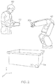
- FIG. 2 is a perspective view of a system for estimating the position and/or orientation of an object according to some embodiments of the inventive concepts.
- a beacon 30 may be attached to a box 10 a .
- the beacon 30 may be attached to the box 10 a with a non-permanent magnet.
- the beacon 30 could be provided with a non-permanent adhesive and/or a suction cup.
- the beacon 30 may be in a defined position and orientation on the box 10 a . The defined position and orientation may be achieved by bringing a reference feature of the beacon 30 into alignment with a reference feature of the box 10 a .
- a robot 40 may include a receiver unit 20 a .
- the receiver unit 20 a may be on an arm of the robot 40 .
- a controller 50 may be used for controlling operation of the robot 40 , the beacon 30 , and/or receiver unit 20 a .
- FIG. 2 illustrates the controller 50 as handheld computer device, such as a tablet computer or smartphone. However, other types of controllers may be used as well, e.g., a stationary control terminal.
- some or all of the operations of the controller 50 described herein may be performed by the robot 40 , the receiver unit 20 a , and/or the beacon 30 .
- some embodiments may not have a separate controller 50 .
- an operator 60 may instruct the system to measure signals transmitted from multiple measurement points of the beacon 30 to the receiver unit 20 a .
- the measurement points of the beacon 30 may be the same as or similar to the measurement points 11 of the first object 10 of FIG. 1 . Accordingly, a detailed description thereof may be omitted for brevity.
- an application may be executed by the controller 50 , i.e., through software installed on the controller 50 , to control the transmission of the signals.
- Each of these measurement points may define a corresponding position in a coordinate system (x, y, z) of the robot 40 .
- the receiver unit 20 a and/or controller 50 may then calculate the position and orientation of the reference feature of the beacon 30 , which due to the alignment also enables determination of the position and orientation of the reference feature of the box 10 a in the coordinate system of the robot 40 .
- the beacon 30 may also include an orientation sensor, which may be the same as or similar to the orientation sensor 12 of the beacon 30.
- the position and orientation of the box 10 a may be determined according to the operations described above with respect to the first object 10 and the second object 20 of FIG. 1 . Accordingly, a detailed description of the determination of the determination of the position and orientation of the box 10 a may be omitted for brevity.
- the position and orientation of the box 10 a may then be used for controlling operation, for example a movement, of the robot 40 .
- FIG. 3 is a block diagram of a device on an object according to some embodiments of the inventive concepts.
- the reference feature of the beacon 30 may be a triangular shaped corner 13 formed by two linear outer edges of the beacon 30 .
- the corner may have an angle of 90 degree, i.e., the edges forming the corner 13 may be perpendicular to each other.
- a remainder of the beacon 30 may be rounded.
- the reference feature on the box 10 a may be an outer corner 14 of the box 10 a .
- the beacon 30 is placed in such a way that the triangular shaped corner 13 points into the outer corner 14 of the box 10 a and the edges of the corner are aligned with edges of the box 10 a .
- the beacon 30 can be easily placed and aligned in the desired position and orientation on the box 10 a .
- the beacon 30 which is aligned in the desired position and orientation, may then be used for determining the position and orientation of the box 10 a in the coordinate system of the robot 40 .
- the beacon 30 may include multiple measurement points 11 a , 11 b , and 11 c and may include an orientation sensor 12 .
- the measurement points 11 a , 11 b , and 11 c and the orientation sensor 12 of the beacon 30 may be the same as or similar to the measurement points 11 and the orientation sensor 12 of the first object 10 of FIG. 1 . Accordingly, a detailed description thereof may be omitted for brevity. From each of the measurement points 11 a , 11 b , and 11 c , the beacon 30 may transmit a signal, which may be received by the receiver unit 20 a .
- the receiver unit 20 a and/or the controller 50 may determine the position of each of the measurement points 11 a , 11 b , and 11 c in the coordinate system of the robot 40 , e.g., using run-time based distance measurements, triangulation calculations, and/or trilateration calculations for each of the measurement points 11 a , 11 b , and 11 c , as described above with respect to the first object 10 and the second object 20 of FIG. 1 .
- multiple measurements may be performed in order to estimate the position of the measurement points 11 a , 11 b , and 11 c .
- multiple measurements may be performed with the receiver unit 20 a being placed in different positions (i.e., by movement of the robot 40 ). This has the benefit of enabling high accuracy without requiring excessive size of the receiver unit 20 a .
- the receiver unit 20 a may include multiple receivers and/or multiple antennas so as to enable triangulation and/or trilateration already for a single position of the receiver unit 20 a.
- the robot 40 may provide an instruction to the receiver unit 20 a to get the positions of the measurement points. In some embodiments, this instruction may be sent by the controller 50 .
- the measurement points 11 a then send their signal.
- the measurement points 11 a , 11 b , and 11 c may send their signals sequentially, according to a preconfigured order in a time-division multiplexing of the signals or may be multiplexed in other ways, e.g., frequency division multiplexing and/or code division multiplexing.
- the sending of the signals may be controlled by the receiver unit 20 a sending an instruction to the beacon 30 to start sending the signals and/or by the receiver unit 20 a sending an instruction to the beacon 30 to stop sending the signals.
- the receiver unit 20 a may receive the signals from the measurement points 11 a , 11 b , 11 c and may calculate the distances between the receiver unit 20 a and each of the measurement points 11 a , 11 b , 11 c . In some embodiments, the calculation may be performed, for example, by the robot 40 and/or by the controller 50 . In some embodiments, the distances may be calculated based on the timing, amplitude, and/or phase of the received signals.
- the receiver unit 20 a and/or the controller 50 may determine the position and orientation of the corner 14 in the coordinate system of the robot 40 .
- the receiver unit 20 a and/or the controller 50 may for example store a management data set which defines an arrangement of the measurement points 11 a , 11 b , and 11 c in relation to the corner 13 or in relation to the corner 14 , when it is aligned with the corner 13 .
- This management data set may be preconfigured or may be selected by the operator 60 . Further, this management data set could also be selected automatically depending on a signal or indicator transmitted by the beacon 30 .
- the position of the corner 14 i.e., the point where the two edges forming the corner 14 meet, may form an origin of a local coordinate system of the box 10 a , with axes of this local coordinate system of the box 10 a being defined by the edges of the corner 14 and the direction perpendicular to these edges.
- the position of the corner 13 i.e., the point where the two edges forming the corner 13 meet, may form an origin of a local coordinate system of the beacon 30 , with axes of this local coordinate system of the beacon 30 being defined by the edges forming the corner 13 of the beacon 30 and the direction perpendicular to these edges.
- a rule for transformation between the coordinate system of the robot 40 and the local coordinate system of the box 10 a and/or the local coordinate system of the beacon 30 may be determined on the basis of the measured positions of the measurement points 11 and the known arrangement of the measurement points 11 in relation to the corner 13 .
- the receiver unit 20 a and/or the controller 50 could determine a transformation matrix implementing this transformation rule.
- the transformation rule may, for example, be used for moving the robot 40 to a certain position defined in the local coordinate system of the box 10 a , e.g., with the aim of picking up an object from this position or placing an object in this position.
- a rule for transformation between the local coordinate system of the beacon 30 and the local coordinate system of the box 10 a may be determined on the basis of the known geometry defined by the alignment of the reference features.
- the alignment of the reference features may also cause full alignment of the local coordinate system of the beacon 30 and the local coordinate system of the box 10 a .
- the alignment of the reference features may indicate that the local coordinate system of the beacon 30 and the local coordinate system of the box 10 a relate to each other by a known transformation, which may include a rotation and/or a translation.
- the beacon 30 could be used for tracking and controlling the position and orientation of a work object in real-time, as it is processed by the robot 40 .
- the beacon 30 may be attached to the work object. If the position or orientation of the work object varies, the corresponding position and orientation defined in the coordinate system of the robot 40 can be updated accordingly.
- the beacon 30 may have a different number measurement points.
- a simplified version of the beacon 30 could provide only two measurement points 11 a and 11 b , which could be used for calculating a two-dimensional orientation of the box 10 a (e.g., an orientation within the x-y-plane).
- multiple beacons 10 may also be placed on multiple reference features of the box 10 a , e.g., to define different corners of the box 10 a.
- Configuring and administrating metadata associated with the beacon 30 may be accomplished using a software application running on the controller 50 .
- This software application may also guide the operator 60 with respect to the placement of the beacon 30 on the object. This may for example help to resolve ambiguities concerning the correct placement of the beacon 30 on the object.
- the object could have multiple reference features which are each suitable for alignment of the beacon 30 .
- the box 10 a may have multiple outer corners which are each in principle suitable for alignment of the beacon 30 .
- Guidance for the operator 60 may then for example involve showing a graphical representation of the box 10 a to the operator 60 and indicating the target position of the beacon 30 in this graphical representation.
- the reference feature of the beacon 30 and the reference feature of the box 10 a may be configured in such a way that there is only one possibility of achieving correct alignment of the reference feature of the beacon 30 and the reference feature of the box 10 a .
- this could be achieved by providing the reference feature of the beacon 30 and the reference feature of the box 10 a with unique key structures matching each other.
- the placement and alignment of the beacon 30 using matching reference features on the beacon 30 and the object may provide intuitive and precise determination of the position and orientation of the object.
- FIG. 4 is a perspective view conceptually illustrating inter mediate operations of methods of estimating the position and/or orientation of an object according to some embodiments of the inventive concepts.
- the measurement points 11 a , 11 b , and 11 c may be spaced apart from each other on an upper surface of the beacon 30 .
- the beacon 30 may transmit signals from each of the measurement points 11 a , 11 b , and 11 c to the receiver unit 20 a of the robot 40 at a first location P 1 .
- the beacon 30 may transmit signals from each of the measurement points 11 a , 11 b , and 11 c to the receiver unit 20 a of the robot 40 at one or more second locations P 2 , P 3 .
- the positions of the measurement points 11 a , 11 b , and 11 c may be determined in the coordinate system of the robot 40 according to operations similar to or the same as those described above with respect to FIGS. 1-3 and detailed description thereof may be omitted for brevity.
- FIGS. 5A and 5B are perspective views conceptually illustrating a difference between first and second measurements of an orientation of an object according to some embodiments of the inventive concepts.
- a position and a first orientation OR 1 of the beacon 30 may be determined based on the measured positions of the measurement points 11 a , 11 b , and 11 c based on the signals received from the measurement points 11 a , 11 b , and 11 c .
- a second orientation OR 2 of the beacon 30 may be determined based on measurements from the orientation sensor 12 a .
- the first orientation OR 1 and the second orientation OR 2 may be determined according to operations that are the same as or similar to those described above with respect to FIGS. 1-4 and detailed descriptions thereof may be omitted accordingly for brevity.
- first orientation OR 1 and the second orientation OR 2 are described with respect to the beacon 30 , embodiments of the inventive concepts are not limited thereto and one or both of the first orientation OR 1 and the second orientation OR 2 may be orientations of the box 10 a of FIG. 2 and/or the first object 10 of FIG. 1 .
- signals are described as being transmitted by the beacon 30 via the measurement points 11 a , 11 b , and 11 c , embodiments are not limited thereto.
- signals may be transmitted by the robot 40 via the receiver unit 20 a , which may include a transmitter, and may be received at the measurement points 11 a , 11 b , and 11 c to determine the locations of the measurement points 11 a , 11 b , and 11 c .
- information about the signals received at the measurement points 11 a , 11 b , and 11 c and/or information about the measurements from the orientation sensor 12 a may be transmitted to the robot 40 and/or the controller 50 via one or more of the measurement points 11 a , 11 b , and 11 c and/or via another communication interface.
- the controller 50 may perform these determinations. While the determination of the locations and/or orientations as being performed by the robot 40 of FIG. 2 , in some embodiments one or more of these determinations may be performed by the controller 50 , the receiver unit 20 a , the robot 40 , the beacon 30 , the orientation sensor 12 a , and/or the box 10 a.
- the first orientation OR 1 may not be aligned with the second orientation OR 2 .
- the difference between the first orientation OR 1 and the second orientation OR 2 may be caused by an error in the determination of the first orientation OR 1 .
- the error in the determination of the first orientation OR 1 may be caused by an error in the determination of the location of one or more of the measurement points 11 a , 11 b , and/or 11 c .
- the estimate of the location of the box 10 a is also based on the determination of the location of the measurement points 11 a , 11 b , and/or 11 c .
- the error in the determination of the location of one or more of the measurement points 11 a , 11 b , and/or 11 c may also cause an error in the estimate of the location of the box 10 a . Accordingly, by comparing the first orientation OR 1 and the second orientation OR 2 to determine the difference between the first orientation OR 1 and the second orientation OR 2 , a magnitude of the error of the estimate of the location of the box 10 a may be estimated.
- FIG. 6 is a flowchart illustrating operations of methods of estimating the position and/or orientation of an object according to some embodiments of the inventive concepts. While the operations of FIG. 6 will be described with reference to the box 10 a and the robot 40 of FIG. 2 , the same or similar operations may be applied to the first object 10 and the second object 20 of FIG. 1 . Moreover, one or more of the operations of FIG. 6 may be performed by the controller 50 of FIG. 2 or by other elements of FIGS. 1-4 described above.
- the robot 40 may determine an estimate of the locations of the measurement points 11 a , 11 b , and 11 c .
- the robot may receive signals receive signals from the measurement points 11 a , 11 b , and 11 c to estimate the locations of the measurement points 11 a , 11 b , and 11 c on the beacon 30 .
- the signals may include measurement signals that are emitted from the measurement points 11 a , 11 b , and 11 c to receiver unit 20 a .
- the robot 40 may transmit measurement signals from a transmitter of the receiver unit 20 a to the measurement points 11 a , 11 b , and 11 c and the signals received at the robot 40 from the measurement points 11 a , 11 b , and 11 c may include measurements of the measurement signals from the measurement points 11 a , 11 b , and 11 c.
- the robot 40 may determine an estimate of the location of the box 10 a based on the estimate of the locations of the measurement points 11 a , 11 b , and 11 c .
- the measurement points 11 a , 11 b , and 11 c may be on the beacon 30 in a known arrangement with respect to an origin of a local coordinate system of the beacon 30 , for example the corner 13 . Accordingly, the location of the origin of the local coordinate system of the beacon 30 may be calculated based on the estimate of the locations of the measurement points 11 a , 11 b , and 11 c .
- the location of the box 10 a may be calculated.
- the robot 40 may determine a first measurement of an orientation of the box 10 a based on the estimate of the locations of the measurement points 11 a , 11 b , and 11 c .
- the measurement points 11 a , 11 b , and 11 c may be arranged in two dimensions to define a plane. Accordingly, an orientation of the plane may be calculated based on the estimate of the locations of the measurement points 11 a , 11 b , and 11 c .
- the first measurement of the orientation of the box 10 a may be calculated.
- the robot may determine a second measurement of the orientation of the box 10 a based on measurements by the orientation sensor 12 a .
- information about the measurements from the orientation sensor 12 a may be transmitted to the robot 40 via one or more of the measurement points 11 a , 11 b , and 11 c and/or via another communication interface.
- the orientation sensor 12 a , the beacon 30 , and/or the box 10 a may calculate the second measurement of the orientation of the box 10 a based on the measurements by the orientation sensor 12 a .
- the robot 40 may calculate the second measurement of the orientation of the box 10 a based on the measurements by the orientation sensor 12 a and/or may transform an orientation measurement from a coordinate system of the beacon 30 and/or of the box 10 a to a coordinate system of the robot 40 to determine the second measurement of the orientation of the box 10 a.
- the robot 40 may determine an accuracy of the estimate of the location of the box 10 a .
- the robot 40 may estimate an error of the estimate of the location of the box 10 a based on a difference between the first measurement of the orientation of the box 10 a and the second measurement of the orientation of the box 10 a .
- the first measurement of the orientation of the box 10 a and the second measurement of the orientation of the box 10 a may be compared to determine a difference between the first measurement of the orientation of the box 10 a and the second measurement of the orientation of the box 10 a .
- the difference between the first measurement of the orientation of the box 10 a and the second measurement of the orientation of the box 10 a may indicate an error in the first measurement of the orientation of the box 10 a .
- the error in the first measurement of the orientation of the box 10 a may be caused by an error in the estimate of the location of one or more of the measurement points 11 a , 11 b , and 11 c .
- the estimate of the location of the box 10 a is also based on the estimate of the location of the measurement points 11 a , 11 b , and 11 c
- the error in the estimate of the location of the one or more of the measurement points 11 a , 11 b , and/or 11 c may also cause an error in the estimate of the location of the box 10 a .
- the error of the estimate of the location of the box 10 a may be estimated based on the difference between the first measurement of the orientation of the box 10 a and the second measurement of the orientation of the box 10 a .
- an accuracy of the measurement of the orientation of the box 10 a may be determined.
- the robot 40 may take an action based on the estimated accuracy of the estimate of the location of the box 10 a .
- the robot 40 may adjust a movement of the robot 40 based on the error of the estimate of the location of the box 10 a .
- the robot 40 may be moved closer to a target location based on the estimate of the location of the box 10 a .
- the target location may be defined based on the estimate of the location of the box 10 a .
- the robot 40 may be moved closer to the target location when the error of the estimate of the location of the box 10 a is less than a predetermined threshold.
- the target location may be adjusted based on the error of the estimate of the location of the box 10 a .
- a robot 40 may be instructed to pick up an object in the box 10 a or place an object in the box 10 a .
- the robot 40 may move towards a target location within the box 10 a , for example by moving an arm of the robot 40 , based on the measurements of the location and/or orientation of the box 10 a.
- the adjusting of the movement of the robot 40 may include avoiding a boundary location based on the error of the estimate of the location of the box 10 a .
- the boundary location may be defined based on the estimate of the location of the box 10 a .
- the boundary location may be adjusted based on the error of the estimate of the location of the box 10 a .
- the robot 40 may define a boundary location, such as a wall of the box 10 a that is to be avoided, based on the measurements of the location and/or orientation of the box 10 a .
- the robot 40 may adjust the boundary location, such as a width of the area to be avoided, based on the error of the estimate of the location of the box 10 a . For example, the robot 40 may avoid a wider area if the error is greater in order to ensure that the robot 40 does not accidentally contact the wall of the box 10 a.
- the action based on the estimated accuracy of the estimate of the location may include adjusting a setting.
- a setting of a tool may be adjusted based on an estimated error in the estimate of the location.
- a setting such as torque and/or rotation speed may be adjusted for a tool such as a screwdriver based on the estimated accuracy of the estimate of the location.
- a setting such as current and/or temperature may be adjusted for a tool such as a welding tool based on the estimated accuracy of the estimate of the location. This may be useful, for example, because a higher current and/or temperature setting may be desired if, based on the estimated accuracy of the estimate of the location, the tool may be at a distance away from an ideal placement.
- FIG. 7 is a flowchart illustrating operations of methods of estimating the position and/or orientation of an object according to some embodiments of the inventive concepts. Some of the operations of FIG. 6 may be similar to or the same as operations described above with respect to FIG. 6 . Accordingly, a detailed description may be omitted for brevity. As with FIG. 6 , while the operations of FIG. 7 will be described with reference to the box 10 a and the robot 40 of FIG. 2 , the same or similar operations may be applied to the first object 10 and the second object 20 of FIG. 1 . Moreover, one or more of the operations of FIG. 7 may be performed by the controller 50 of FIG. 2 or by other elements of FIGS. 1-4 described above.
- the robot 40 may begin at a first location P 1 .
- the receiver unit 20 a of the robot 40 may begin at the first location P 1 .
- the robot 40 may determine a measurement of a distance from the first location P 1 to the measurement point 11 a .
- the distance may be measured using a signal received at the receiving unit 20 a from the measurement point 11 a .
- the signal may include an ultrasonic signal, a radio signal, and/or a radar signal.
- the distance may be measured, for example, using a timing, an amplitude, and/or a phase of the received signal.
- the robot 40 may determine measurements of distances from the first location P 1 to the measurement points 11 b and 11 c , respectively, in a similar manner.
- the signals may include measurement signals that are emitted from the measurement points 11 a , 11 b , and 11 c to receiver unit 20 a .
- the robot 40 may transmit measurement signals from a transmitter of the receiver unit 20 a to the measurement points 11 a , 11 b , and 11 c and the signals received at the robot 40 from the measurement points 11 a , 11 b , and 11 c may include measurements of the measurement signals from the measurement points 11 a , 11 b , and 11 c.
- the robot 40 may move to a second location P 2 .
- the robot may move an arm that includes the receiving unit 20 a to the second location P 2 .
- the robot 40 may determine measurements of distances from the second location P 2 to the measurement points 11 a , 11 b , and 11 c , respectively.
- the robot 40 may move to another second location P 3 .
- the robot 40 may determine measurements of distances from the second location P 3 to the measurement points 11 a , 11 b , and 11 c , respectively.
- the robot 40 may determine measurements of distances to each of the measurement points 11 a , 11 b , and 11 c , from the first location P 1 and from each of the second locations P 2 and P 3 .
- the robot 40 may determine measurements of the locations of the measurement points 11 a , 11 b , and 11 c based on the signals received from the measurement, points 11 a , 11 b , and 11 c at each of the locations P 1 , P 2 , and P 3 .
- the locations of the measurement points 11 a , 11 b , and 11 c may be measured using run-time based distance measurements, triangulation calculations, and/or trilateration calculations.
- the robot 40 may determine an estimate of the location of the beacon 30 based on the estimate of the locations of the measurement points 11 a , 11 b , and 11 c .
- the measurement points 11 a , 11 b , and 11 c may be on the beacon 30 in a known arrangement with respect to an origin of a local coordinate system of the beacon 30 , for example the corner 13 . Accordingly, the location of the origin of the local coordinate system of the beacon 30 may be calculated based on the estimate of the locations of the measurement points 11 a , 11 b , and 11 c.
- the robot 40 may determine an estimate of the location of the box 10 a based on the estimate of the location of the beacon 30 on the box 10 a . For example, based on the alignment of the reference feature of the beacon 30 with the reference feature of the box 10 a , such as an alignment of the corner 13 with the corner 14 , the arrangement of the measurement points 11 a , 11 b , and 11 c with respect to the origin of the local coordinate system of the beacon 30 , and the estimate of the locations of the measurement points 11 a , 11 b , and 11 c , the location of the box 10 a may be calculated.
- the robot 40 may determine a first measurement of an orientation of the box 10 a based on the estimate of the locations of the measurement points 11 a , 11 b , and 11 c .
- the measurement points 11 a , 11 b , and 11 c may be arranged in two dimensions to define a plane. Accordingly, an orientation of the plane may be calculated based on the estimate of the locations of the measurement points 11 a , 11 b , and 11 c .
- the first measurement of the orientation of the box 10 a may be calculated.
- the robot may determine a second measurement of the orientation of the box 10 a based on measurements by the orientation sensor 12 a .
- information about the measurements from the orientation sensor 12 a may be transmitted to the robot 40 via one or more of the measurement points 11 a , 11 b , and 11 c and/or via another communication interface.
- the orientation sensor 12 a , the beacon 30 , and/or the box 10 a may calculate the second measurement of the orientation of the box 10 a based on the measurements by the orientation sensor 12 a .
- the robot 40 may calculate the second measurement of the orientation of the box 10 a based on the measurements by the orientation sensor 12 a and/or may transform an orientation measurement from a coordinate system of the beacon 30 and/or of the box 10 a to a coordinate system of the robot 40 to determine the second measurement of the orientation of the box 10 a.
- the robot 40 may compare the first measurement of the orientation of the box 10 a to the second measurement of the orientation of the box 10 a .
- the first measurement of the orientation of the box 10 a and the second measurement of the orientation of the box 10 a may be compared to determine a difference between the first measurement of the orientation of the box 10 a and the second measurement of the orientation of the box 10 a .
- the difference between the first measurement of the orientation of the box 10 a and the second measurement of the orientation of the box 10 a may indicate an error in the first measurement of the orientation of the box 10 a .
- the error in the first measurement of the orientation of the box 10 a may be caused by an error in the estimate of the location of one or more of the measurement points 11 a , 11 b , and 11 c.
- the robot 40 may determine an accuracy of the estimate of the location of the box 10 a .
- the robot 40 may estimate an error of the estimate of the location of the box 10 a based on the difference between the first measurement of the orientation of the box 10 a and the second measurement of the orientation of the box 10 a .
- the estimate of the location of the box 10 a is also based on the estimate of the location of the measurement points 11 a , 11 b , and 11 c
- the error in the estimate of the location of the one or more of the measurement points 11 a , 11 b , and/or 11 c may also cause an error in the estimate of the location of the box 10 a .
- the error of the estimate of the location of the box 10 a may be estimated based on the difference between the first measurement of the orientation of the box 10 a and the second measurement of the orientation of the box 10 a .
- an accuracy of the measurement of the orientation of the box 10 a may be determined.
- the robot 40 may take an action based on the estimated accuracy of the estimate of the location of the box 10 a .
- the robot 40 may adjust a movement of the robot 40 based on the error of the estimate of the location of the box 10 a .
- the robot 40 may be moved closer to a target location based on the estimate of the location of the box 10 a .
- the target location may be defined based on the estimate of the location of the box 10 a .
- the robot 40 may be moved closer to the target location when the error of the estimate of the location of the box 10 a is less than a predetermined threshold.
- the target location may be adjusted based on the error of the estimate of the location of the box 10 a .
- a robot 40 may be instructed to pick up an object in the box 10 a or place an object in the box 10 a .
- the robot 40 may move towards a target location within the box 10 a , for example by moving an arm of the robot 40 , based on the measurements of the location and/or orientation of the box 10 a.
- the adjusting of the movement of the robot 40 may include avoiding a boundary location based on the error of the estimate of the location of the box 10 a .
- the boundary location may be defined based on the estimate of the location of the box 10 a .
- the boundary location may be adjusted based on the error of the estimate of the location of the box 10 a .
- the robot 40 may define a boundary location, such as a wall of the box 10 a that is to be avoided, based on the measurements of the location and/or orientation of the box 10 a .
- the robot 40 may adjust the boundary location, such as a width of the area to be avoided, based on the error of the estimate of the location of the box 10 a . For example, the robot 40 may avoid a wider area if the error is greater in order to ensure that the robot 40 does not accidentally contact the wall of the box 10 a.
- the action based on the estimated accuracy of the estimate of the location may include adjusting a setting.
- a setting of a tool may be adjusted based on an estimated error in the estimate of the location.
- a setting such as torque and/or rotation speed may be adjusted for a tool such as a screwdriver based on the estimated accuracy of the estimate of the location.
- a setting such as current and/or temperature may be adjusted for a tool such as a welding tool based on the estimated accuracy of the estimate of the location. This may be useful, for example, because a higher current and/or temperature setting may be desired if, based on the estimated accuracy of the estimate of the location, the tool may be at a distance away from an ideal placement.
- FIG. 8 is a block diagram schematically illustrating a system for estimating the position and/or orientation of an object according to some embodiments of the inventive concepts.
- a receiver 800 may be utilized for implementing the above concepts.
- the receiver 800 may be the interface 21 of FIG. 1 and/or the receiver unit 20 a of FIG. 2 .
- the receiver 800 may include a beacon interface 810 .
- the beacon interface 810 may be configured to receive signals from one or more beacons, such as the beacon 30 of FIG. 2 .
- the beacon interface 810 may support reception of ultrasonic signals, radio signals, and/or of radar signals.
- the beacon interface 810 may support directional reception of the signals, e.g., based on a multi-antenna technology or multi-receiver technology.
- the beacon interface 810 may support bidirectional transmission.
- the beacon interface 810 may be used for sending instructions or other control information to the beacon(s), such as instructions to start or stop sending signals.
- the receiver 800 may include a control interface 820 .
- the control interface 820 may connect the receiver 800 to an external controller, such as the controller 50 of FIG. 2 .
- the control interface 820 may connect the receiver 800 to a robot, such as the robot 40 of FIG. 2 .
- the control interface 820 may include a wireless interface, e.g., a radio interface, or a wire-based interface.
- the control interface 820 may provide the receiver 800 with information concerning the arrangement of the measurement points 11 a , 11 b , and 11 c of the beacon 30 in relation to a reference feature of the beacon 30 and/or with information concerning the geometry of an object of which the position and orientation is to be determined.
- the receiver 800 may include a control unit, such as one or more processors 840 and a memory 850 that is coupled to the processor.
- the beacon interface 810 and the memory 850 may be coupled to the processor(s) 840 , e.g., using one or more internal bus systems of the receiver 800 .
- the memory 850 may include a non-volatile memory device.
- the memory 850 may include a measurement control module 860 and/or a position/orientation calculation module 870 .
- the program code modules 860 and 870 may include program code that is configured to be executed by the processor(s) 840 .
- the measurement control module 860 may implement functionalities of controlling the above-mentioned functionalities of performing measurements on the basis of signals received from one or more measurement points of the beacon 30 .
- the position/orientation calculation 870 may implement the above-described functionalities of calculating the position and/or orientation of the object on which the beacon is placed and aligned.
- the receiver 800 may also include other elements, e.g., structures or program code modules for implementing functionalities of an ultrasonic, radio, or radar receiver.
- FIG. 9 is a block diagram schematically illustrating a device for estimating the position and/or orientation of an object according to some embodiments of the inventive concepts.
- a beacon 900 may be utilized for implementing the above concepts.
- the beacon 900 may be the first object 10 of FIG. 1 and/or the beacon 30 of FIG. 2 .
- the beacon 900 may include a signal interface 910 .
- the signal interface 910 may be configured to send signals to a receiver, such as the receiver unit 20 a of FIG. 2 .
- the signal interface 910 may support sending of ultrasonic signals, of radio signals, and/or of radar signals.
- the signal interface 910 may support bidirectional transmission.
- the signal interface 910 may receive instructions or other control information, such as the above-mentioned instructions to start or stop sending signals.
- the beacon 900 may include a plurality of measurement points 911 that are coupled to the signal interface.
- the plurality of measurement points 911 may include a plurality of antennae that are on a surface of the beacon 900 .
- the beacon may include an orientation sensor 920 .
- the orientation sensor may, for example, be based on an accelerometer and/or on a gyroscope.
- the orientation sensor may be an inertial measurement unit.
- the beacon 900 may include with one or more processors 940 and a memory 950 that is coupled to the processor.
- the signal interface 910 , the memory 950 , and/or the orientation sensor 920 may be coupled to the processor(s) 940 , e.g., using one or more internal bus systems of the beacon 900 .
- the memory 950 may include a non-volatile memory device.
- the memory 950 may include a transmit control module 960 and/or a measurement control module 970 .
- the program code modules 960 and 970 may include program code that is configured to be executed by the processor(s) 940 .
- the transmit control module 960 may implement the above described functionalities for sending the signals to the receiver unit 20 a on the robot 40 .
- the measurement control module 970 may implement functionalities for performing measurements locally at the beacon 30 itself, e.g., using the orientation sensor 920 .
- the beacon 900 may also include other elements, e.g., structures or program code modules for implementing functionalities of an ultrasonic and/or radio transmitter.
- the beacon interface 610 could be used for sending the signals
- the signal interface 910 could be used for receiving the signals.
- the signal interface 910 could be used for reporting measurements on the signals to some other device.
- the memory 650 could include a transmit control module for implementing the functionalities for transmitting the signals.
- the memory 950 could include a reception control module to implement the functionalities for receiving the signals, and the measurement control module 970 could then may implement functionalities for performing measurements on the received signals.
- FIG. 10 is a block diagram schematically illustrating a system for estimating the position and/or orientation of an object according to some embodiments of the inventive concepts.
- a system 1000 may be utilized for implementing the above concepts.
- the system 1000 may be the second object 20 of FIG. 1 and/or the robot 40 of FIG. 2 .
- the system 1000 may include a receiver 1010 configured to receive signals from one or more objects.
- the receiver 1010 may be configured to receive signals from a beacon, such as the beacon 30 of FIG. 2 .
- the receiver 1010 may be configured to receive the signals from a plurality of measurement points on an object.
- the receiver 1010 may be configured to receive the signals from the measurement points 11 a , 11 b , and 11 c of the beacon 30 of FIG. 3 .
- the receiver 1010 may support reception of ultrasonic signals, radio signals, and/or of radar signals.
- the receiver 1010 may support directional reception of the signals, e.g., based on a multi-antenna technology or multi-receiver technology.
- the receiver 1010 may support bidirectional transmission.
- the receiver 1010 may be used for sending instructions or other control information to the beacon(s), such as instructions to start or stop sending signals.
- the system 1000 may include a first estimating circuit 1020 configured to estimate locations of the plurality of measurement points on the object based on the signals received by the receiver 1010 from the plurality of measurement points on the object.
- the first estimating circuit 1020 may perform the operation 601 of FIG. 6 and/or one or more of the operations 701 to 714 of FIG. 7 .
- the system 1000 may include a first determining circuit 1030 configured to determine an estimate of a location of the object based on the estimating of the locations of the plurality of measurement points on the object.
- the first determining circuit 1030 may perform the operation 602 of FIG. 6 and/or one or more of the operations 715 to 716 of FIG. 7 .
- the system 1000 may include a second determining circuit 1040 configured to determine a first measurement of an orientation of the object based on the estimating of the locations of the plurality of measurement points on the object.
- the second determining circuit 1040 may perform the operation 603 of FIG. 6 and/or the operation 717 of FIG. 7 .
- the system 1000 may include a third determining circuit 1050 configured to determine a second measurement of the orientation of the object based on measurements by an orientation sensor on the object.
- the third determining circuit 1050 may perform the operation 604 of FIG. 6 and/or the operation 718 of FIG. 7 .
- the system 1000 may include a second estimating circuit 1060 configured to estimate an error of the estimate of the location of the object based on a difference between the first measurement of the orientation of the object and the second measurement of the orientation of the object.
- the second estimating circuit 1060 may perform the operation 605 of FIG. 6 and/or one or more of the operations 719 to 720 of FIG. 7 .
- the system 1000 may include an adjusting circuit 1070 .
- the adjusting circuit 1070 may be configured to adjust a movement of the system 1000 based on the error of the estimate of the location of the object.
- the adjusting circuit 1070 may be configured to adjust a setting, for example a setting of a tool.
- the adjusting circuit 1070 may perform the operation 606 of FIG. 6 and/or the operation 721 of FIG. 7 .
- one or more of the first estimating circuit 1020 , the first determining circuit 1030 , the second determining circuit 1040 , the third determining circuit 1050 , the second estimating circuit 1060 and the adjusting circuit 1070 may be implemented in hardware, software, or any combination thereof.
- one or more of the circuits may include one or more processors and a non-volatile memory coupled to the processor, such as the processors 840 and the memory 850 of FIG. 8 .
- the non-volatile memory may include computer readable program code that, when executed by the processor, causes the processor to perform the described operations of the one or more of the circuits.
- Embodiments of the inventive concepts may provide determination of the position and/or orientation of an object using a single device placed on the object. Moreover, embodiments of the inventive concepts may provide improved methods of determining the position and/or orientation of an object by providing an estimate of an error of the estimate of the location of the object. Some embodiments of the inventive concepts may reduce mishandling and/or damage of an object by, for example, a robot. Some embodiments of the inventive concepts may provide compensation of measurement errors based on location measurements in conjunction with orientation measurements. Compensation of measurement errors based on location measurements and orientation measures may substantially improve the determination of the position and/or orientation of an object and thus may improve performance of operations by, for example, a robot.
- inventive concepts may be applied in connection with various kinds of robotic systems and also in applications not related to robotics, such as tracking of an object or virtual reality applications. Further, the inventive concepts may utilize various types of beacons and receivers.
Landscapes
- Engineering & Computer Science (AREA)
- Radar, Positioning & Navigation (AREA)
- Remote Sensing (AREA)
- Physics & Mathematics (AREA)
- General Physics & Mathematics (AREA)
- Robotics (AREA)
- Computer Networks & Wireless Communication (AREA)
- Mechanical Engineering (AREA)
- Automation & Control Theory (AREA)
- Electromagnetism (AREA)
- Position Fixing By Use Of Radio Waves (AREA)
Abstract
Description
Claims (20)
Applications Claiming Priority (1)
| Application Number | Priority Date | Filing Date | Title |
|---|---|---|---|
| PCT/US2017/038231 WO2018236343A1 (en) | 2017-06-20 | 2017-06-20 | POSITION ESTIMATING VERIFICATION SYSTEMS, METHODS, AND DEVICES USING AN ORIENTATION SENSOR |
Publications (2)
| Publication Number | Publication Date |
|---|---|
| US20200057134A1 US20200057134A1 (en) | 2020-02-20 |
| US11187777B2 true US11187777B2 (en) | 2021-11-30 |
Family
ID=59297363
Family Applications (1)
| Application Number | Title | Priority Date | Filing Date |
|---|---|---|---|
| US16/610,943 Expired - Fee Related US11187777B2 (en) | 2017-06-20 | 2017-06-20 | Systems, methods, and devices for verification of position estimation using an orientation sensor |
Country Status (2)
| Country | Link |
|---|---|
| US (1) | US11187777B2 (en) |
| WO (1) | WO2018236343A1 (en) |
Families Citing this family (2)
| Publication number | Priority date | Publication date | Assignee | Title |
|---|---|---|---|---|
| WO2023030660A1 (en) * | 2021-09-06 | 2023-03-09 | Fraba B.V. | Sensor device and sensor system for monitoring a machine |
| CN114002645B (en) * | 2021-10-29 | 2024-10-25 | 西安电子科技大学 | A variable-scale space-time self-adjustment method for the problem of near singularity of positioning solution or axis correlation of positioning error |
Citations (5)
| Publication number | Priority date | Publication date | Assignee | Title |
|---|---|---|---|---|
| WO2001002874A1 (en) | 1999-07-02 | 2001-01-11 | Kvh Industries, Inc. | Antenna attitude determination by averaging gyros signals against phase signals |
| WO2005108020A1 (en) | 2004-05-04 | 2005-11-17 | Kuka Roboter Gmbh | Robot-controlled optical measurement array, and method and auxiliary mechanism for calibrating said measurement array |
| DE102005000732A1 (en) | 2005-01-04 | 2006-07-13 | Siemens Ag | Radio-based location system with synthetic aperture |
| WO2012024434A1 (en) | 2010-08-17 | 2012-02-23 | Qualcomm Incorporated | Method and apparatus for rf-based ranging with multiple antennas |
| EP2546674A1 (en) | 2011-07-15 | 2013-01-16 | Astrium GmbH | Plarform relative navigation using range measurements |
-
2017
- 2017-06-20 US US16/610,943 patent/US11187777B2/en not_active Expired - Fee Related
- 2017-06-20 WO PCT/US2017/038231 patent/WO2018236343A1/en not_active Ceased
Patent Citations (6)
| Publication number | Priority date | Publication date | Assignee | Title |
|---|---|---|---|---|
| WO2001002874A1 (en) | 1999-07-02 | 2001-01-11 | Kvh Industries, Inc. | Antenna attitude determination by averaging gyros signals against phase signals |
| WO2005108020A1 (en) | 2004-05-04 | 2005-11-17 | Kuka Roboter Gmbh | Robot-controlled optical measurement array, and method and auxiliary mechanism for calibrating said measurement array |
| US20080216552A1 (en) * | 2004-05-04 | 2008-09-11 | Kuka Roboter Gmbh | Robot-Controlled Optical Measurement Array, and Method and Auxiliary Mechanism for Calibrating Said Measurement Array |
| DE102005000732A1 (en) | 2005-01-04 | 2006-07-13 | Siemens Ag | Radio-based location system with synthetic aperture |
| WO2012024434A1 (en) | 2010-08-17 | 2012-02-23 | Qualcomm Incorporated | Method and apparatus for rf-based ranging with multiple antennas |
| EP2546674A1 (en) | 2011-07-15 | 2013-01-16 | Astrium GmbH | Plarform relative navigation using range measurements |
Non-Patent Citations (1)
| Title |
|---|
| Notification of Transmittal of the International Search Report and the Written Opinion of the International Searching Authority, or the Declaration, in corresponding PCT Application No. PCT/US2017/038231 (dated Mar. 16, 2018). |
Also Published As
| Publication number | Publication date |
|---|---|
| WO2018236343A1 (en) | 2018-12-27 |
| US20200057134A1 (en) | 2020-02-20 |
Similar Documents
| Publication | Publication Date | Title |
|---|---|---|
| CN107817469B (en) | Indoor positioning method based on ultra-wideband ranging in non-line-of-sight environment | |
| JP2004212400A (en) | Position and direction estimation system for robots | |
| CN104076348A (en) | Radar beyond visual range base line passive cooperative localization method | |
| US10627475B2 (en) | Pose estimation using radio frequency identification (RFID) tags | |
| CN110621447A (en) | Robot conveyor calibration method, robot system and control system | |
| CN105737852B (en) | Laser rangefinder position measurement and correction system and method | |
| US11187777B2 (en) | Systems, methods, and devices for verification of position estimation using an orientation sensor | |
| CN113359769A (en) | Indoor autonomous mobile robot composite navigation method and device | |
| KR20080078576A (en) | Position Estimation Apparatus and Method Using Forward Link AAO | |
| US20180229374A1 (en) | Detection of engagement of robot with object | |
| US20150160329A1 (en) | Determining location and orientation of directional tranceivers | |
| US10819449B2 (en) | Method and system for near-field localization | |
| US11620846B2 (en) | Data processing method for multi-sensor fusion, positioning apparatus and virtual reality device | |
| US11485024B2 (en) | Determination of object position by aligned device placement | |
| CN113124852B (en) | Multi-sensor fusion positioning system and positioning method | |
| CN110703188B (en) | An RFID-based six-degree-of-freedom attitude estimation system | |
| KR101094990B1 (en) | Simultaneous Mapping Based Location Recognition Using Orthogonal Antennas in Underwater Environments | |
| Zarrini et al. | Directional of arrival tag response for reverse RFID localization | |
| KR102036080B1 (en) | Portable positioning device and method for operating portable positioning device | |
| Fernau et al. | On the Precision of Single-Receiver Ultra-Wideband Tracking using Combined Distance and Angle of Arrival Measurement | |
| US9568586B2 (en) | Method for positioning a to-be-positioned device | |
| JP2021127993A (en) | Direction measurement method for heavy machinery | |
| US20190022862A1 (en) | Position definition in coordinate system of a robot by device placement | |
| JP2024130591A (en) | Information processing device and position measurement system | |
| KR102006003B1 (en) | Apparatus and method for estimating position using flaoa |
Legal Events
| Date | Code | Title | Description |
|---|---|---|---|
| AS | Assignment |
Owner name: SONY CORPORATION, JAPAN Free format text: ASSIGNMENT OF ASSIGNORS INTEREST;ASSIGNORS:FAENGE, THOMAS;FALK, MATTIAS;BERGKVIST, HANNES;AND OTHERS;SIGNING DATES FROM 20191024 TO 20191029;REEL/FRAME:050912/0719 |
|
| FEPP | Fee payment procedure |
Free format text: ENTITY STATUS SET TO UNDISCOUNTED (ORIGINAL EVENT CODE: BIG.); ENTITY STATUS OF PATENT OWNER: LARGE ENTITY |
|
| STPP | Information on status: patent application and granting procedure in general |
Free format text: DOCKETED NEW CASE - READY FOR EXAMINATION |
|
| STPP | Information on status: patent application and granting procedure in general |
Free format text: NOTICE OF ALLOWANCE MAILED -- APPLICATION RECEIVED IN OFFICE OF PUBLICATIONS |
|
| AS | Assignment |
Owner name: SONY GROUP CORPORATION, JAPAN Free format text: CHANGE OF NAME;ASSIGNOR:SONY CORPORATION;REEL/FRAME:057723/0357 Effective date: 20210422 |
|
| STPP | Information on status: patent application and granting procedure in general |
Free format text: PUBLICATIONS -- ISSUE FEE PAYMENT VERIFIED |
|
| STCF | Information on status: patent grant |
Free format text: PATENTED CASE |
|
| FEPP | Fee payment procedure |
Free format text: MAINTENANCE FEE REMINDER MAILED (ORIGINAL EVENT CODE: REM.); ENTITY STATUS OF PATENT OWNER: LARGE ENTITY |
|
| LAPS | Lapse for failure to pay maintenance fees |
Free format text: PATENT EXPIRED FOR FAILURE TO PAY MAINTENANCE FEES (ORIGINAL EVENT CODE: EXP.); ENTITY STATUS OF PATENT OWNER: LARGE ENTITY |
|
| STCH | Information on status: patent discontinuation |
Free format text: PATENT EXPIRED DUE TO NONPAYMENT OF MAINTENANCE FEES UNDER 37 CFR 1.362 |
|
| FP | Lapsed due to failure to pay maintenance fee |
Effective date: 20251130 |