US11183687B2 - Method of producing electrode plate and electrode plate - Google Patents
Method of producing electrode plate and electrode plate Download PDFInfo
- Publication number
- US11183687B2 US11183687B2 US16/139,469 US201816139469A US11183687B2 US 11183687 B2 US11183687 B2 US 11183687B2 US 201816139469 A US201816139469 A US 201816139469A US 11183687 B2 US11183687 B2 US 11183687B2
- Authority
- US
- United States
- Prior art keywords
- conductive particles
- particles
- active material
- material layer
- electrode plate
- Prior art date
- Legal status (The legal status is an assumption and is not a legal conclusion. Google has not performed a legal analysis and makes no representation as to the accuracy of the status listed.)
- Active, expires
Links
Images


Classifications
-
- H—ELECTRICITY
- H01—ELECTRIC ELEMENTS
- H01M—PROCESSES OR MEANS, e.g. BATTERIES, FOR THE DIRECT CONVERSION OF CHEMICAL ENERGY INTO ELECTRICAL ENERGY
- H01M4/00—Electrodes
- H01M4/02—Electrodes composed of, or comprising, active material
- H01M4/36—Selection of substances as active materials, active masses, active liquids
- H01M4/362—Composites
- H01M4/366—Composites as layered products
-
- H—ELECTRICITY
- H01—ELECTRIC ELEMENTS
- H01M—PROCESSES OR MEANS, e.g. BATTERIES, FOR THE DIRECT CONVERSION OF CHEMICAL ENERGY INTO ELECTRICAL ENERGY
- H01M10/00—Secondary cells; Manufacture thereof
- H01M10/05—Accumulators with non-aqueous electrolyte
- H01M10/052—Li-accumulators
- H01M10/0525—Rocking-chair batteries, i.e. batteries with lithium insertion or intercalation in both electrodes; Lithium-ion batteries
-
- H—ELECTRICITY
- H01—ELECTRIC ELEMENTS
- H01M—PROCESSES OR MEANS, e.g. BATTERIES, FOR THE DIRECT CONVERSION OF CHEMICAL ENERGY INTO ELECTRICAL ENERGY
- H01M4/00—Electrodes
- H01M4/02—Electrodes composed of, or comprising, active material
- H01M4/04—Processes of manufacture in general
- H01M4/0402—Methods of deposition of the material
- H01M4/0404—Methods of deposition of the material by coating on electrode collectors
-
- H—ELECTRICITY
- H01—ELECTRIC ELEMENTS
- H01M—PROCESSES OR MEANS, e.g. BATTERIES, FOR THE DIRECT CONVERSION OF CHEMICAL ENERGY INTO ELECTRICAL ENERGY
- H01M4/00—Electrodes
- H01M4/02—Electrodes composed of, or comprising, active material
- H01M4/13—Electrodes for accumulators with non-aqueous electrolyte, e.g. for lithium-accumulators; Processes of manufacture thereof
- H01M4/139—Processes of manufacture
-
- H—ELECTRICITY
- H01—ELECTRIC ELEMENTS
- H01M—PROCESSES OR MEANS, e.g. BATTERIES, FOR THE DIRECT CONVERSION OF CHEMICAL ENERGY INTO ELECTRICAL ENERGY
- H01M4/00—Electrodes
- H01M4/02—Electrodes composed of, or comprising, active material
- H01M4/62—Selection of inactive substances as ingredients for active masses, e.g. binders, fillers
- H01M4/624—Electric conductive fillers
-
- H—ELECTRICITY
- H01—ELECTRIC ELEMENTS
- H01M—PROCESSES OR MEANS, e.g. BATTERIES, FOR THE DIRECT CONVERSION OF CHEMICAL ENERGY INTO ELECTRICAL ENERGY
- H01M4/00—Electrodes
- H01M4/02—Electrodes composed of, or comprising, active material
- H01M2004/026—Electrodes composed of, or comprising, active material characterised by the polarity
- H01M2004/028—Positive electrodes
-
- H—ELECTRICITY
- H01—ELECTRIC ELEMENTS
- H01M—PROCESSES OR MEANS, e.g. BATTERIES, FOR THE DIRECT CONVERSION OF CHEMICAL ENERGY INTO ELECTRICAL ENERGY
- H01M4/00—Electrodes
- H01M4/02—Electrodes composed of, or comprising, active material
- H01M4/04—Processes of manufacture in general
- H01M4/043—Processes of manufacture in general involving compressing or compaction
- H01M4/0435—Rolling or calendering
-
- H—ELECTRICITY
- H01—ELECTRIC ELEMENTS
- H01M—PROCESSES OR MEANS, e.g. BATTERIES, FOR THE DIRECT CONVERSION OF CHEMICAL ENERGY INTO ELECTRICAL ENERGY
- H01M4/00—Electrodes
- H01M4/02—Electrodes composed of, or comprising, active material
- H01M4/04—Processes of manufacture in general
- H01M4/0471—Processes of manufacture in general involving thermal treatment, e.g. firing, sintering, backing particulate active material, thermal decomposition, pyrolysis
-
- Y—GENERAL TAGGING OF NEW TECHNOLOGICAL DEVELOPMENTS; GENERAL TAGGING OF CROSS-SECTIONAL TECHNOLOGIES SPANNING OVER SEVERAL SECTIONS OF THE IPC; TECHNICAL SUBJECTS COVERED BY FORMER USPC CROSS-REFERENCE ART COLLECTIONS [XRACs] AND DIGESTS
- Y02—TECHNOLOGIES OR APPLICATIONS FOR MITIGATION OR ADAPTATION AGAINST CLIMATE CHANGE
- Y02E—REDUCTION OF GREENHOUSE GAS [GHG] EMISSIONS, RELATED TO ENERGY GENERATION, TRANSMISSION OR DISTRIBUTION
- Y02E60/00—Enabling technologies; Technologies with a potential or indirect contribution to GHG emissions mitigation
- Y02E60/10—Energy storage using batteries
Definitions
- the present disclosure relates to a method of producing an electrode plate that includes a current collector foil and an active material layer which is formed on the current collector foil and contains active material particles and conductive particles, and the electrode plate.
- an electrode plate including a current collector foil and an active material layer formed on the current collector foil is known.
- Such an electrode plate is produced by, for example, the following method. That is, an active material paste in which active material particles and conductive particles are dispersed in a solvent is prepared. Then, the active material paste is applied to the current collector foil using a coating device such as a die coater, and an undried active material layer is formed on the current collector foil. Then, the undried active material layer is heated and dried to form an active material layer.
- a roll press machine including a first roller, a second roller that is disposed parallel to the first roller with a gap therebetween, and a third roller that is disposed parallel to the second roller with a gap therebetween is prepared.
- the above particle aggregate is passed between the first roller and the second roller, and an undried film is formed on the second roller.
- the undried film is transferred onto the current collector foil that has passed between the second roller and the third roller, and the undried active material layer is formed on the current collector foil.
- the undried active material layer is heated and dried to form an active material layer.
- Japanese Unexamined Patent Application Publication No. 2017-54637 (refer to FIG. 2 and FIG. 3 in JP 2017-54637 A) may be exemplified.
- the present disclosure provides a method of producing an electrode plate through which it is possible to easily produce an electrode plate including an active material layer having favorable conductivity while the active material layer is formed using a particle aggregate including wet particles and the electrode plate.
- a first aspect of the present disclosure is a method of producing an electrode plate including a current collector foil and an active material layer which is formed on the current collector foil and contains active material particles.
- the method includes mixing the active material particles, the conductive particles, and a solvent, and performing granulating to form a particle aggregate including wet particles, forming an undried active material layer on the current collector foil using the particle aggregate, and drying the undried active material layer and forming the active material layer.
- the conductive particles include first conductive particles and second conductive particles.
- the first conductive particles have a three-dimensional structure in which primary particles with an average primary particle size D1 of 30 nm to 80 nm are connected to each other and have an average structure length X1 of 260 nm to 500 nm.
- the second conductive particles have a three-dimensional structure in which primary particles with an average primary particle size D2 of 8 nm to 13 nm are connected to each other and have an average structure length X2 of 80 nm to 250 nm.
- the particle aggregate including wet particles is formed using conductive particles composed of the first conductive particles and second conductive particles, and additionally, the active material layer is formed using the particle aggregate. Since the first conductive particles have a large average primary particle size D1 of 30 nm or more, even though extremely many primary particles are not connected to each other, it is possible to easily form first conductive particles with an average structure length X1 of 260 nm to 500 nm.
- the first conductive particles have an average primary particle size D1 of 80 nm or less, the number of primary particles constituting the first conductive particles contained in the active material layer is too small (contact points between the active material particles and the primary particles of the first conductive particles are too few), and thus it is possible to prevent the conductivity of the active material layer from decreasing.
- the first conductive particles have a large average structure length X1 of 260 nm or more, the dispersibility is favorable. Therefore, it is possible for the first conductive particles to uniformly disperse in the wet particles and to uniformly disperse in the undried active material layer and the active material layer.
- the first conductive particles have an average structure length X1 of 500 nm or less, the number of first conductive particles contained in the active material layer is too small, and thus it is possible to prevent the conductivity of the active material layer from decreasing.
- the second conductive particles have an average primary particle size D2 of 8 nm or more, even though extremely many primary particles are not connected to each other, it is possible to easily form second conductive particles with an average structure length X2 of 80 nm to 250 nm.
- the second conductive particles have an average primary particle size D2 of 13 nm or less, the number of primary particles constituting the second conductive particles contained in the active material layer is large (the number of contact points between the active material particles and the primary particles of the second conductive particles is large), and thus it is possible to increase the conductivity of the active material layer.
- the active material layer is formed using the particle aggregate including wet particles, compared to a case in which an active material layer is formed using only the first conductive particles as the conductive particles and a case in which an active material layer is formed using only the second conductive particles as the conductive particles, it is possible to easily produce an electrode plate including an active material layer having favorable conductivity.
- both the “first conductive particles” and the “second conductive particles” have three-dimensional structures (also referred to as “structures”) in which primary particles are connected to each other as described above.
- the “average structure length” is obtained by observing a plurality of (for example, 100) conductive particles under a transmission electron microscope (TEM), drawing the smallest circles in which conductive particles are inscribed, measuring diameters of the circles, and calculating an average value thereof.
- TEM transmission electron microscope
- carbon black particles for example, acetylene black particles, may be exemplified.
- a proportion of the first conductive particles in the conductive particles may be 20 wt % to 45 wt %.
- the second conductive particles may include third conductive particles which have a three-dimensional structure in which primary particles with an average primary particle size D3 of 8 nm to 13 nm are connected to each other and have an average structure length X3 of 150 nm to 250 nm.
- the second conductive particles may further include fourth conductive particles which have a three-dimensional structure in which primary particles with an average primary particle size D4 of 8 nm to 13 nm are connected to each other and have an average structure length X4 of 80 nm to 110 nm.
- the second conductive particles include third conductive particles, and the third conductive particles have an average structure length X3 of 150 nm to 250 nm, a conductive path according to the third conductive particles is easily formed in gaps between the active material particles, and it is possible to improve the conductivity of the active material layer.
- a proportion of the third conductive particles in the second conductive particles may be 10 wt % to 60 wt %.
- a proportion of the third conductive particles in the second conductive particles is 10 wt % to 60 wt %, it is possible to further improve the conductivity of the active material layer.
- a second aspect of the present disclosure is an electrode plate including a current collector foil and a dried active material layer formed into a film on the current collector foil using a particle aggregate including wet particles obtained by mixing active material particles, conductive particles, and a solvent, and performing granulating.
- the conductive particles include first conductive particles and second conductive particles.
- the first conductive particles have a three-dimensional structure in which primary particles with an average primary particle size D1 of 30 nm to 80 nm are connected to each other and have an average structure length X1 of 260 nm to 500 nm.
- the second conductive particles have a three-dimensional structure in which primary particles with an average primary particle size D2 of 8 nm to 13 nm are connected to each other and have an average structure length X2 of 80 nm to 250 nm.
- the conductive particles are composed of the first conductive particles and the second conductive particles.
- the active material layer is formed using the particle aggregate including wet particles, it is possible to further improve the conductivity of the active material layer compared to when only the first conductive particles are used as the conductive particles or when only the second conductive particles are used as the conductive particles.
- a proportion of the first conductive particles in the conductive particles may be 20 wt % to 45 wt %.
- the second conductive particles may include third conductive particles which have a three-dimensional structure in which primary particles with an average primary particle size D3 of 8 nm to 13 nm are connected to each other and have an average structure length X3 of 150 nm to 250 nm.
- the second conductive particles may further include fourth conductive particles which have a three-dimensional structure in which primary particles with an average primary particle size D4 of 8 nm to 13 nm are connected to each other and have an average structure length X4 of 80 nm to 110 nm.
- the second conductive particles include the third conductive particles and the fourth conductive particles. Thus, it is possible to further improve the conductivity of the active material layer.
- a proportion of the third conductive particles in the second conductive particles may be 10 wt % to 60 wt %.
- a proportion of the third conductive particles in the second conductive particles is 10 wt % to 60 wt %, it is possible to further improve the conductivity of the active material layer.
- FIG. 1 is a perspective view of a positive electrode plate according to an embodiment
- FIG. 2A is an explanatory diagram showing a form example of first conductive particles
- FIG. 2B is an explanatory diagram showing a form example of third conductive particles
- FIG. 2C is an explanatory diagram showing a form example of fourth conductive particles
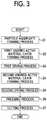
- FIG. 3 is a flowchart of a method of producing a positive electrode plate according to an embodiment
- FIG. 4 is an explanatory diagram showing a particle aggregate forming process in the method of producing a positive electrode plate according to the embodiment
- FIG. 5 is an explanatory diagram showing a first undried active material layer forming process in the method of producing a positive electrode plate according to the embodiment
- FIG. 6 is a graph showing electrical resistance ratios (IV resistance ratios) of batteries of Examples 1 to 6 and Comparative Examples 1 and 2;
- FIG. 7 is a graph showing the relationship between a proportion of first conductive particles in conductive particles and IV resistance ratios in the batteries of Examples 1 to 3 and Comparative Examples 1 and 2;
- FIG. 8 is a graph showing the relationship between a proportion of third conductive particles in second conductive particles and IV resistance ratios in the batteries of Examples 3 to 6.
- FIG. 1 shows a perspective view of a positive electrode plate (electrode plate) 1 according to the present embodiment.
- a longitudinal direction EH, a width direction FH and a thickness direction GH of the positive electrode plate 1 are defined as directions shown in FIG. 1 .
- the positive electrode plate 1 is a band-like positive electrode plate that is used to produce a rectangular and closed type lithium ion secondary battery mounted in a vehicle such as a hybrid vehicle, a plug-in hybrid vehicle, and an electric vehicle, and specifically, to produce a flat-wound type electrode body.
- the positive electrode plate 1 includes a current collector foil 3 made of a band-like aluminum foil that extends in the longitudinal direction EH.
- a first active material layer 5 is formed in a band shape on an area that is a part of a first main surface 3 a of the current collector foil 3 in the width direction FH and extends in the longitudinal direction EH.
- a second active material layer 6 is formed in a band shape on an area that is a part of a second main surface 3 b on the side opposite to the current collector foil 3 in the width direction FH and extends in the longitudinal direction EH.
- One end of the positive electrode plate 1 in the width direction FH becomes an exposed part 1 m in which there is no first active material layer 5 or second active material layer 6 in the thickness direction GH and the current collector foil 3 is exposed in the thickness direction GH.
- the first active material layer 5 and the second active material layer 6 each include active material particles 11 , conductive particles 13 , and a binding agent 19 .
- the active material particles 11 are lithium transition metal composite oxide particles, and more specifically, lithium nickel cobalt manganese oxide particles.
- the binding agent 19 is polyvinylidene fluoride (PVDF).
- the conductive particles 13 include first conductive particles 14 and second conductive particles 15 .
- a proportion of the first conductive particles 14 in the conductive particles 13 is 20 wt % to 45 wt % (30 wt % in the present embodiment), and a proportion of the second conductive particles 15 in the conductive particles 13 is the remaining 70 wt %.
- the second conductive particles 15 include third conductive particles 16 and fourth conductive particles 17 .
- a proportion of the third conductive particles 16 in the second conductive particles 15 is 57 wt % (a proportion of the third conductive particles 16 in the entire conductive particles 13 is 40 wt %).
- a proportion of the fourth conductive particles 17 in the second conductive particles 15 is 43 wt % (a proportion of the fourth conductive particles 17 in the entire conductive particles 13 is 30 wt %).
- Conductive particles of the first conductive particles 14 to the fourth conductive particles 17 are all acetylene black particles.
- the average structure length X1 is obtained by observing the first conductive particles 14 under a transmission electron microscope (TEM), drawing the smallest circles in which the first conductive particles 14 are inscribed (circle indicated by a dashed line in FIG. 2A ), measuring diameters of the circles, and calculating an average value thereof.
- Average structure lengths X2 to X4 to be described below are obtained in the same manner (refer to FIGS. 2B and 2C ).
- a particle aggregate 22 including wet particles 21 is formed (refer to FIG. 4 ).
- the wet particles 21 are particles in a wet state including the plurality of active material particles 11 (lithium nickel cobalt manganese oxide particles in the present embodiment), the plurality of conductive particles 13 (acetylene black particles in the present embodiment), the binding agent 19 (PVDF in the present embodiment), and a solvent 20 (N-methyl-2-pyrrolidone (NMP) in the present embodiment).
- a solid fraction of the particle aggregate 22 is 70 wt % or more (75 wt % in the present embodiment) (a proportion of the solvent 20 is 25 wt %).
- a stirring type mixing and granulating device capable of mixing and granulating materials is prepared.
- the first conductive particles 14 and the second conductive particles 15 are prepared, and first conductive particles, third conductive particles, and fourth conductive particles are mixed at a weight ratio of 30:40:30 to obtain conductive particles 13 .
- the average primary particle size D1 is large at 30 nm or more, even though extremely many primary particles 14 p are not connected to each other, it is possible to easily form acetylene black particles with an average structure length X1 of 260 nm to 500 nm.
- the average primary particle size D2 is 8 nm or more, even though extremely many primary particles 15 p are not connected to each other, it is possible to easily form acetylene black particles with an average structure length X2 of 80 nm to 250 nm.
- the active material particles 11 are put into the stirring type mixing and granulating device and mixed, the conductive particles 13 are added thereto, and these are dried and mixed at 4,500 rpm for 20 seconds. Then, a binding agent solution in which the binding agent 19 is dissolved is added to the solvent 20 , and mixing and granulating are performed at 800 rpm for 20 seconds. Thereby, the particle aggregate 22 including the wet particles 21 with a particle size of about 1 mm to 2 mm is obtained.
- an undried film 22 x is formed from the particle aggregate 22 including the wet particles 21 , and additionally, the undried film 22 x is transferred to the first main surface 3 a of the current collector foil 3 , and a first undried active material layer 5 x is formed on the current collector foil 3 .
- a positive electrode plate having the first undried active material layer 5 x on the current collector foil 3 is referred to as a “one-undried-side positive electrode plate 1 x .”
- the first undried active material layer forming process S 2 is performed using an electrode plate production device 100 schematically shown in FIG. 5 .
- the electrode plate production device 100 includes three rollers. Specifically, the electrode plate production device 100 includes a first roller 110 , a second roller 120 that is disposed parallel to the first roller 110 with a first gap KG 1 therebetween, and a third roller 130 that is disposed parallel to the second roller 120 with a second gap KG 2 therebetween. In addition, the electrode plate production device 100 includes an aggregate supply unit 140 configured to supply the particle aggregate 22 including the wet particles 21 toward the first gap KG 1 above the first gap KG 1 between the first roller 110 and the second roller 120 .
- the first to third rollers 110 , 120 , and 130 are rotated in rotation directions indicated by arrows in FIG. 5 . That is, the first roller 110 and the third roller 130 are rotated in the same rotation direction (clockwise in the present embodiment), and the second roller 120 is rotated in a direction opposite thereto (counterclockwise in the present embodiment).
- the particle aggregate 22 including the wet particles 21 is put into the aggregate supply unit 140 .
- the supplied particle aggregate 22 is supplied toward the first gap KG 1 between the first roller 110 and the second roller 120 , passes through a gap between the first roller 110 and the second roller 120 , and forms the undried film 22 x in a film form that is pushed downward in FIG. 5 .
- the undried film 22 x is held on the second roller 120 and conveyed toward the third roller 130 .
- the undried film 22 x held on the second roller 120 is transferred to the first main surface 3 a of the current collector foil 3 between the second roller 120 and the third roller 130 .
- the band-like current collector foil 3 is withdrawn from a supply roll (not shown) and wound around the third roller 130 , and thus is passed between the second roller 120 and the third roller 130 .
- the current collector foil 3 conveyed by the third roller 130 comes in contact with the undried film 22 x held on the second roller 120 between the second roller 120 and the third roller 130 . Then, the undried film 22 x is transferred onto the first main surface 3 a of the current collector foil 3 between the second roller 120 and the third roller 130 , and the first undried active material layer 5 x is formed on the current collector foil 3 .
- the one-undried-side positive electrode plate 1 x having the first undried active material layer 5 x on the current collector foil 3 is conveyed rightward in FIG. 5 by the third roller 130 .
- the first undried active material layer 5 x on the current collector foil 3 is dried and the first active material layer 5 is formed.
- the one-undried-side positive electrode plate 1 x is conveyed into a drying device (not shown), hot air is blown to the first undried active material layer 5 x in the one-undried-side positive electrode plate 1 x , the solvent 20 remaining on the first undried active material layer 5 x is evaporated, and thus the first active material layer 5 is formed. Thereby, a one side positive electrode plate 1 y having the first active material layer 5 on the current collector foil 3 is formed.
- the undried film 22 x is formed from the particle aggregate 22 including the wet particles 21 , and additionally, the undried film 22 x is transferred to the other second main surface 3 b of the current collector foil 3 , and a second undried active material layer 6 x is formed on the current collector foil 3 .
- the second undried active material layer 6 x is formed in the first undried active material layer forming process S 2 using the electrode plate production device 100 .
- the dried first active material layer 5 is formed on the first main surface 3 a of the current collector foil 3
- the second undried active material layer 6 x that is undried is formed on the second main surface 3 b of the current collector foil 3 .
- This positive electrode plate is referred to as a “one-dried-side double-side positive electrode plate 1 z.”
- a “second drying process S 5 ” the second undried active material layer 6 x on the current collector foil 3 is dried and the second active material layer 6 is formed.
- the one-dried-side double-side positive electrode plate 1 z is conveyed into a drying device (not shown), hot air is blown to the second undried active material layer 6 x in the one-dried-side double-side positive electrode plate 1 z , and the second active material layer 6 is formed. Therefore, a positive electrode plate 1 w including the current collector foil 3 , the first active material layer 5 and the second active material layer 6 is formed.
- a “pressing process S 6 ” the positive electrode plate 1 w is pressed by a roll press machine (not shown), and the densities of the first active material layer 5 and the second active material layer 6 are increased.
- a “cutting process S 7 ” the center of the positive electrode plate 1 w in the width direction FH is cut in the longitudinal direction EH. Thus, the positive electrode plate 1 shown in FIG. 1 is completed.
- Examples 1 to 6 and Comparative Examples 1 and 2 as shown in Table 1, 8 types of positive electrode plates were produced in the same manner as in the embodiment except that the conductive particles 13 were varied.
- the positive electrode plate of Example 5 was the same as the positive electrode plate 1 of the embodiment.
- the first active material layer 5 and the second active material layer 6 were formed using only the first conductive particles 14 as the conductive particles 13 .
- the first active material layer 5 and the second active material layer 6 were formed using only the second conductive particles 15 as the conductive particles 13 .
- Example 1 In Examples 1 to 3 and Comparative Example 2, only the fourth conductive particles 17 were used as the second conductive particles 15 .
- Example 6 only the third conductive particles 16 were used as the second conductive particles 15 .
- the third conductive particles 16 and the fourth conductive particles 17 were used as the second conductive particles 15 .
- batteries were produced using the positive electrode plates of Examples 1 to 6 and Comparative Examples 1 and 2, and IV resistance values of the batteries were measured.
- negative electrode plates that were the same in Examples 1 to 6 and Comparative Examples 1 and 2, negative electrode plates including an active material layer containing active material particles (natural graphite) and a binding agent (carboxymethyl cellulose (CMC)) on both main surfaces of a current collector foil made of a band-like copper foil were prepared.
- the negative electrode plates and the positive electrode plates according to Examples 1 to 6 and Comparative Examples 1 and 2 were laminated with a pair of band-like separators therebetween and wound around the axis and thereby flat-wound type electrode bodies were formed. Then, the electrode bodies and a non-aqueous electrolyte solution were accommodated in a rectangular battery case to constitute the batteries.
- the conductive particles 13 included only the first conductive particles 14 . Since the first conductive particles 14 had a large average structure length X1 of 300 nm, the number of the conductive particles 13 (only the first conductive particles 14 ) contained in the first active material layer 5 and the second active material layer 6 was smaller than the number of the conductive particles 13 contained in the first active material layer 5 and the second active material layer 6 of Examples 1 to 6 and Comparative Example 2. Therefore, it was thought that the conductivities of the first active material layer 5 and the second active material layer 6 were lowered and the IV resistance values of the batteries were higher.
- the conductive particles 13 included only the second conductive particles 15 . Since the second conductive particles 15 had a small average structure length X2 of 160 nm, when the active material particles 11 and the conductive particles 13 (only the second conductive particles 15 ) were mixed together, it was difficult to uniformly disperse the conductive particles 13 and the conductive particles 13 tended to aggregate with each other.
- the conductive particles 13 were composed of the first conductive particles 14 and the second conductive particles 15 . Since the first conductive particles 14 had an average primary particle size D1 of 50 nm, the number of primary particles constituting the first conductive particles 14 contained in the first active material layer 5 and the second active material layer 6 was too small, and thus it was possible to prevent the conductivities of the first active material layer 5 and the second active material layer 6 from decreasing. In addition, since the first conductive particles 14 had a large average structure length X1 of 300 nm, the dispersibility was favorable.
- the first conductive particles 14 it was possible for the first conductive particles 14 to uniformly disperse in the wet particles 21 and to uniformly disperse in the first active material layer 5 and the second active material layer 6 .
- the first conductive particles 14 since the first conductive particles 14 had an average structure length X1 of 300 nm, the number of first conductive particles 14 contained in the first active material layer 5 and the second active material layer 6 was too small, and thus it was possible to prevent the conductivities of the first active material layer 5 and the second active material layer 6 from decreasing.
- the second conductive particles 15 had an average primary particle size D2 of 10 nm, the number of primary particles constituting the second conductive particles 15 contained in the first active material layer 5 and the second active material layer 6 was too large, and thus it was possible to increase the conductivities of the first active material layer 5 and the second active material layer 6 .
- the second conductive particles 15 had an average structure length X2 of 160 nm and the average structure length X1 of the first conductive particles 14 was smaller than 300 nm, a conductive path according to the second conductive particles 15 was easily formed in gaps between the active material particles 11 .
- the second conductive particles 15 were composed of at least the third conductive particles 16 between the third conductive particles 16 and the fourth conductive particles 17 . Since the third conductive particles 16 had an average structure length X3 of 200 nm, a conductive path according to the third conductive particles 16 was easily formed in gaps between the active material particles 11 , and it was possible to improve the conductivities of the first active material layer 5 and the second active material layer 6 .
- the particle aggregate 22 including the wet particles 21 was formed using the conductive particles 13 composed of the first conductive particles 14 and the second conductive particles 15 , and additionally, the first active material layer 5 and the second active material layer 6 were formed using the particle aggregate 22 . Since the first conductive particles 14 had a large average primary particle size D1 of 30 nm or more (50 nm in the present embodiment), even though extremely many primary particles 14 p were not connected to each other, it was possible to easily form the first conductive particles 14 with an average structure length X1 of 260 nm to 500 nm.
- the first conductive particles 14 had an average primary particle size D1 of 80 nm or less (50 nm in the present embodiment), the number of primary particles constituting the first conductive particles 14 contained in the first active material layer 5 and the second active material layer 6 was too small (contact points between the active material particles 11 and the primary particles 14 p of the first conductive particles 14 were too few), and thus it was possible to prevent the conductivities of the first active material layer 5 and the second active material layer 6 from decreasing.
- the first conductive particles 14 had a large average structure length X1 of 260 nm or more (300 nm in the present embodiment), the dispersibility was favorable. Therefore, it was possible for the first conductive particles 14 to uniformly disperse in the wet particles 21 and to uniformly disperse in the first active material layer 5 and the second active material layer 6 .
- the first conductive particles 14 had an average structure length X1 of 500 nm or less (300 nm in the present embodiment), the number of first conductive particles 14 contained in the first active material layer 5 and the second active material layer 6 was too small, and thus it was possible to prevent the conductivities of the first active material layer 5 and the second active material layer 6 from decreasing.
- the second conductive particles 15 had an average primary particle size D2 of 8 nm or more (10 nm in the present embodiment), even though extremely many primary particles 15 p were not connected to each other, it was possible to easily form the second conductive particles 15 with an average structure length X2 of 80 nm to 250 nm.
- the second conductive particles 15 had an average primary particle size D2 of 13 nm or less (10 nm in the present embodiment), the number of primary particles constituting the second conductive particles 15 contained in the first active material layer 5 and the second active material layer 6 was too large (the number of contact points between the active material particles 11 and the primary particles 15 p of the second conductive particles 15 was too large), and thus it was possible to increase the conductivities of the first active material layer 5 and the second active material layer 6 .
- the positive electrode plate 1 while the first active material layer 5 and the second active material layer 6 were formed using the particle aggregate 22 including the wet particles 21 , it was possible to easily produce the positive electrode plate 1 including the first active material layer 5 and the second active material layer 6 having favorable conductivity compared to a case in which only the first conductive particles 14 were used as the conductive particles 13 and a case in which only the second conductive particles 15 were used as the conductive particles 13 .
- a proportion of the first conductive particles 14 in the conductive particles 13 was 20 wt % to 45 wt % (30 wt % in the present embodiment). Thereby, it was possible to further improve the conductivities of the first active material layer 5 and the second active material layer 6 .
- the second conductive particles 15 were composed of the third conductive particles 16 and the fourth conductive particles 17 . Since the third conductive particles 16 had an average structure length X3 of 150 nm to 250 nm (200 nm in the present embodiment), a conductive path according to the third conductive particles 16 was easily formed in gaps between the active material particles 11 , and it was possible to improve the conductivities of the first active material layer 5 and the second active material layer 6 .
- a proportion of the third conductive particles 16 in the second conductive particles 15 was 10 wt % to 60 wt %.
- the present disclosure has been described above with reference to the embodiments, the present disclosure is not limited to the above embodiments, and various modifications can be made without departing from the spirit and scope of the disclosure.
- the positive electrode plate 1 has been exemplified as the electrode plate in the embodiments, the present disclosure can be applied to a negative electrode plate and a method of producing the same.
Landscapes
- Chemical & Material Sciences (AREA)
- Chemical Kinetics & Catalysis (AREA)
- Electrochemistry (AREA)
- General Chemical & Material Sciences (AREA)
- Engineering & Computer Science (AREA)
- Manufacturing & Machinery (AREA)
- Materials Engineering (AREA)
- Composite Materials (AREA)
- Battery Electrode And Active Subsutance (AREA)
- Electric Double-Layer Capacitors Or The Like (AREA)
Abstract
Description
| TABLE 1 | |||
| Details of third and fourth | |||
| Proportion in mixed | conductive particles | ||
| conductive particles (wt %) | (proportion in second |
| Second | conductive particles) (wt %) |
| First | conductive | Third | Fourth | |||
| conductive | particles | conductive | conductive | |||
| particles | D2 = 10 nm | particles | particles | IV | ||
| D1 = 50 nm | X2 = 100 nm | D3 = 10 nm | D4 = 10 nm | resistance | ||
| X1 = 300 nm | to 200 nm | X3 = 200 nm | X4 = 100 | ratio | ||
| Comparative |
| 100 | 0 | 0 (0) | 0 (0) | 100 | |
| Example 1 | |||||
| |
0 | 100 | 0 (0) | 100 (100) | 110 |
| Example 2 | |||||
| Example 1 | 70 | 30 | 0 (0) | 30 (100) | 97 |
| Example 2 | 50 | 50 | 0 (0) | 50 (100) | 83 |
| Example 3 | 30 | 70 | 0 (0) | 70 (100) | 78 |
| Example 4 | 30 | 70 | 10 (14) | 60 (86) | 74 |
| Example 5 | 30 | 70 | 40 (57) | 30 (43) | 74 |
| Example 6 | 30 | 70 | 70 (0) | 0 (0) | 75 |
Claims (14)
Applications Claiming Priority (3)
| Application Number | Priority Date | Filing Date | Title |
|---|---|---|---|
| JP2017192696A JP6822369B2 (en) | 2017-10-02 | 2017-10-02 | Electrode plate manufacturing method |
| JP2017-192696 | 2017-10-02 | ||
| JPJP2017-192696 | 2017-10-02 |
Publications (2)
| Publication Number | Publication Date |
|---|---|
| US20190103606A1 US20190103606A1 (en) | 2019-04-04 |
| US11183687B2 true US11183687B2 (en) | 2021-11-23 |
Family
ID=65896270
Family Applications (1)
| Application Number | Title | Priority Date | Filing Date |
|---|---|---|---|
| US16/139,469 Active 2039-01-22 US11183687B2 (en) | 2017-10-02 | 2018-09-24 | Method of producing electrode plate and electrode plate |
Country Status (3)
| Country | Link |
|---|---|
| US (1) | US11183687B2 (en) |
| JP (1) | JP6822369B2 (en) |
| CN (1) | CN109599527B (en) |
Citations (6)
| Publication number | Priority date | Publication date | Assignee | Title |
|---|---|---|---|---|
| US20130089780A1 (en) * | 2011-10-06 | 2013-04-11 | Tomoyuki Uezono | Method for manufacturing lithium secondary battery |
| US20160141597A1 (en) * | 2014-11-19 | 2016-05-19 | Toyota Jidosha Kabushiki Kaisha | Method of manufacturing negative electrode for nonaqueous electrolyte secondary battery |
| JP2016154100A (en) | 2015-02-20 | 2016-08-25 | トヨタ自動車株式会社 | Nonaqueous electrolyte secondary battery and method for manufacturing the same |
| JP2016164837A (en) | 2015-03-06 | 2016-09-08 | トヨタ自動車株式会社 | Method for manufacturing positive electrode and positive electrode |
| US20170069906A1 (en) | 2015-09-08 | 2017-03-09 | Toyota Jidosha Kabushiki Kaisha | Method of manufacturing non-aqueous liquid electrolyte secondary battery |
| US20190173087A1 (en) * | 2016-08-31 | 2019-06-06 | Sekisui Chemical Co., Ltd. | Electrode material for electricity storage devices, electrode for electricity storage devices, and electricity storage device |
Family Cites Families (10)
| Publication number | Priority date | Publication date | Assignee | Title |
|---|---|---|---|---|
| EP2034542B1 (en) * | 2006-06-27 | 2015-06-03 | Kao Corporation | Composite positive electrode material for lithium ion battery and battery using the same |
| JP2008047512A (en) * | 2006-07-18 | 2008-02-28 | Nissan Motor Co Ltd | Positive electrode for non-aqueous electrolyte secondary battery |
| JP5906578B2 (en) * | 2011-04-07 | 2016-04-20 | 日立化成株式会社 | Positive electrode mixture for lithium ion secondary battery, positive electrode for lithium ion secondary battery and lithium ion secondary battery using the same |
| JP5947688B2 (en) * | 2011-12-28 | 2016-07-06 | パナソニック株式会社 | Electrode composite and photoelectric device including the same |
| KR20160020237A (en) * | 2014-08-13 | 2016-02-23 | 삼성에스디아이 주식회사 | Cathode material, cathode including the same, and lithium battery including the cathode |
| JP6179499B2 (en) * | 2014-11-27 | 2017-08-16 | トヨタ自動車株式会社 | Method for producing positive electrode for lithium ion secondary battery |
| JP6809473B2 (en) * | 2015-09-16 | 2021-01-06 | 宇部興産株式会社 | Fibrous carbon-containing lithium-titanium composite oxide powder, electrode sheet using it, and power storage device using it |
| CN105336958B (en) * | 2015-10-14 | 2017-04-05 | 广东天劲新能源科技股份有限公司 | Graphene/CNTs/Super P combined conductive agents, combined conductive agent slurry and preparation method thereof |
| CN107046815B (en) * | 2015-12-09 | 2020-06-30 | 株式会社Lg化学 | Positive electrode material slurry for lithium secondary battery comprising at least two conductive materials and lithium secondary battery using the same |
| JP2019061734A (en) * | 2015-12-25 | 2019-04-18 | 株式会社日立製作所 | Lithium ion secondary battery |
-
2017
- 2017-10-02 JP JP2017192696A patent/JP6822369B2/en active Active
-
2018
- 2018-09-21 CN CN201811107013.3A patent/CN109599527B/en active Active
- 2018-09-24 US US16/139,469 patent/US11183687B2/en active Active
Patent Citations (9)
| Publication number | Priority date | Publication date | Assignee | Title |
|---|---|---|---|---|
| US20130089780A1 (en) * | 2011-10-06 | 2013-04-11 | Tomoyuki Uezono | Method for manufacturing lithium secondary battery |
| US20160141597A1 (en) * | 2014-11-19 | 2016-05-19 | Toyota Jidosha Kabushiki Kaisha | Method of manufacturing negative electrode for nonaqueous electrolyte secondary battery |
| JP2016154100A (en) | 2015-02-20 | 2016-08-25 | トヨタ自動車株式会社 | Nonaqueous electrolyte secondary battery and method for manufacturing the same |
| US20160248085A1 (en) * | 2015-02-20 | 2016-08-25 | Toyota Jidosha Kabushiki Kaisha | Non-aqueous electrolyte secondary battery and method for manufacturing the same |
| CN105914346A (en) | 2015-02-20 | 2016-08-31 | 丰田自动车株式会社 | Non-aqueous electrolyte secondary battery and method for manufacturing the same |
| JP2016164837A (en) | 2015-03-06 | 2016-09-08 | トヨタ自動車株式会社 | Method for manufacturing positive electrode and positive electrode |
| US20170069906A1 (en) | 2015-09-08 | 2017-03-09 | Toyota Jidosha Kabushiki Kaisha | Method of manufacturing non-aqueous liquid electrolyte secondary battery |
| JP2017054637A (en) | 2015-09-08 | 2017-03-16 | トヨタ自動車株式会社 | Method for producing non-aqueous electrolyte secondary battery |
| US20190173087A1 (en) * | 2016-08-31 | 2019-06-06 | Sekisui Chemical Co., Ltd. | Electrode material for electricity storage devices, electrode for electricity storage devices, and electricity storage device |
Also Published As
| Publication number | Publication date |
|---|---|
| CN109599527A (en) | 2019-04-09 |
| CN109599527B (en) | 2022-03-08 |
| JP2019067649A (en) | 2019-04-25 |
| JP6822369B2 (en) | 2021-01-27 |
| US20190103606A1 (en) | 2019-04-04 |
Similar Documents
| Publication | Publication Date | Title |
|---|---|---|
| KR101761524B1 (en) | Positive electrode material slurry for a lithium secondary battery comprising at least two conductive material and lithium secondary battery using same | |
| JP5684226B2 (en) | Fluorinated binder composites and carbon nanotubes for lithium battery positive electrodes | |
| WO2018051667A1 (en) | Lithium ion secondary battery | |
| TW202235566A (en) | Binder that is composite of single-walled carbon nanotubes and ptfe, and composition for electrode production and secondary battery using same | |
| CN108028371A (en) | Cathode materials for rechargeable solid-state lithium-ion batteries | |
| WO2012114590A1 (en) | Electrode for non-aqueous electrolyte secondary battery, method for producing same, and non-aqueous electrolyte secondary battery | |
| US20230290955A1 (en) | Carbon-based conductive agent, secondary battery, and electrical device | |
| US20160285103A1 (en) | Positive electrode active material for lithium ion secondary battery, positive electrode for lithium ion secondary battery, and lithium ion secondary battery using same | |
| WO2023090453A1 (en) | Positive electrode mixture layer, electroconductive auxiliary agent, positive electrode mixture, and lithium ion secondary battery | |
| JP2013196804A (en) | Mixture slurry, manufacturing method thereof, electrode formed by mixture slurry, and battery | |
| JP6698374B2 (en) | Lithium ion secondary battery | |
| US11183687B2 (en) | Method of producing electrode plate and electrode plate | |
| US10497931B2 (en) | Method of manufacturing lithium ion secondary battery | |
| CN120693698A (en) | Negative electrode for secondary battery and lithium secondary battery including the same | |
| JP2020087597A (en) | electrode | |
| JP2024058944A (en) | Negative electrode mixture, negative electrode manufacturing method, negative electrode, and secondary battery | |
| JP7745591B2 (en) | Method for manufacturing positive electrode, and positive electrode | |
| KR102874890B1 (en) | Composition for secondary battery, positive electrode and positive electrode composite layer | |
| JP7819467B2 (en) | Electrode sheet manufacturing method | |
| JP2020170637A (en) | Electrode sheet manufacturing method | |
| US20250316698A1 (en) | Positive electrode composition, positive electrode, battery, method for producing positive electrode-forming coating liquid, method for producing positive electrode, and method for producing battery | |
| US20250062337A1 (en) | Electrode comprising lithium-rich nickel manganese oxides | |
| US20250336916A1 (en) | Positive electrode composition, positive electrode, battery, method for manufacturing positive-electrode-forming coating liquid, method for manufacturing positive electrode, and method for manufacturing battery | |
| JP2025166684A (en) | Electrode paste for power storage device | |
| US20250323269A1 (en) | Positive electrode composition, positive electrode, battery, method for manufacturing positive electrode formation coating liquid, method for manufacturing positive electrode, and method for manufacturing battery |
Legal Events
| Date | Code | Title | Description |
|---|---|---|---|
| AS | Assignment |
Owner name: TOYOTA JIDOSHA KABUSHIKI KAISHA, JAPAN Free format text: ASSIGNMENT OF ASSIGNORS INTEREST;ASSIGNOR:AKIYAMA, NAOHISA;REEL/FRAME:047130/0468 Effective date: 20180625 |
|
| FEPP | Fee payment procedure |
Free format text: ENTITY STATUS SET TO UNDISCOUNTED (ORIGINAL EVENT CODE: BIG.); ENTITY STATUS OF PATENT OWNER: LARGE ENTITY |
|
| STPP | Information on status: patent application and granting procedure in general |
Free format text: DOCKETED NEW CASE - READY FOR EXAMINATION |
|
| STPP | Information on status: patent application and granting procedure in general |
Free format text: NON FINAL ACTION MAILED |
|
| STPP | Information on status: patent application and granting procedure in general |
Free format text: RESPONSE TO NON-FINAL OFFICE ACTION ENTERED AND FORWARDED TO EXAMINER |
|
| STPP | Information on status: patent application and granting procedure in general |
Free format text: FINAL REJECTION MAILED |
|
| STPP | Information on status: patent application and granting procedure in general |
Free format text: RESPONSE AFTER FINAL ACTION FORWARDED TO EXAMINER |
|
| STPP | Information on status: patent application and granting procedure in general |
Free format text: NOTICE OF ALLOWANCE MAILED -- APPLICATION RECEIVED IN OFFICE OF PUBLICATIONS |
|
| STPP | Information on status: patent application and granting procedure in general |
Free format text: PUBLICATIONS -- ISSUE FEE PAYMENT VERIFIED |
|
| STCF | Information on status: patent grant |
Free format text: PATENTED CASE |
|
| MAFP | Maintenance fee payment |
Free format text: PAYMENT OF MAINTENANCE FEE, 4TH YEAR, LARGE ENTITY (ORIGINAL EVENT CODE: M1551); ENTITY STATUS OF PATENT OWNER: LARGE ENTITY Year of fee payment: 4 |