US11180123B2 - Vehicle control system - Google Patents
Vehicle control system Download PDFInfo
- Publication number
- US11180123B2 US11180123B2 US16/476,702 US201816476702A US11180123B2 US 11180123 B2 US11180123 B2 US 11180123B2 US 201816476702 A US201816476702 A US 201816476702A US 11180123 B2 US11180123 B2 US 11180123B2
- Authority
- US
- United States
- Prior art keywords
- target data
- input
- determination time
- braking
- control unit
- Prior art date
- Legal status (The legal status is an assumption and is not a legal conclusion. Google has not performed a legal analysis and makes no representation as to the accuracy of the status listed.)
- Active, expires
Links
- 238000012544 monitoring process Methods 0.000 claims abstract description 38
- 238000000034 method Methods 0.000 claims description 60
- 238000004891 communication Methods 0.000 claims description 59
- 230000008569 process Effects 0.000 claims description 56
- 230000007423 decrease Effects 0.000 claims description 26
- 238000004904 shortening Methods 0.000 claims description 17
- 102100037009 Filaggrin-2 Human genes 0.000 description 13
- 101000878281 Homo sapiens Filaggrin-2 Proteins 0.000 description 13
- 230000007704 transition Effects 0.000 description 11
- 101000906633 Homo sapiens Chloride channel protein 2 Proteins 0.000 description 9
- 101000620620 Homo sapiens Placental protein 13-like Proteins 0.000 description 9
- 102100022336 Placental protein 13-like Human genes 0.000 description 9
- 230000014509 gene expression Effects 0.000 description 9
- 102100023457 Chloride channel protein 1 Human genes 0.000 description 8
- 101000906651 Homo sapiens Chloride channel protein 1 Proteins 0.000 description 8
- 230000001172 regenerating effect Effects 0.000 description 8
- 238000005259 measurement Methods 0.000 description 6
- 230000005856 abnormality Effects 0.000 description 3
- 230000009471 action Effects 0.000 description 2
- 230000008859 change Effects 0.000 description 2
- 230000000694 effects Effects 0.000 description 2
- 230000007246 mechanism Effects 0.000 description 2
- 230000002123 temporal effect Effects 0.000 description 2
- 238000013459 approach Methods 0.000 description 1
- 238000010586 diagram Methods 0.000 description 1
- 230000003252 repetitive effect Effects 0.000 description 1
Images


Classifications
-
- B—PERFORMING OPERATIONS; TRANSPORTING
- B60—VEHICLES IN GENERAL
- B60T—VEHICLE BRAKE CONTROL SYSTEMS OR PARTS THEREOF; BRAKE CONTROL SYSTEMS OR PARTS THEREOF, IN GENERAL; ARRANGEMENT OF BRAKING ELEMENTS ON VEHICLES IN GENERAL; PORTABLE DEVICES FOR PREVENTING UNWANTED MOVEMENT OF VEHICLES; VEHICLE MODIFICATIONS TO FACILITATE COOLING OF BRAKES
- B60T8/00—Arrangements for adjusting wheel-braking force to meet varying vehicular or ground-surface conditions, e.g. limiting or varying distribution of braking force
- B60T8/32—Arrangements for adjusting wheel-braking force to meet varying vehicular or ground-surface conditions, e.g. limiting or varying distribution of braking force responsive to a speed condition, e.g. acceleration or deceleration
- B60T8/88—Arrangements for adjusting wheel-braking force to meet varying vehicular or ground-surface conditions, e.g. limiting or varying distribution of braking force responsive to a speed condition, e.g. acceleration or deceleration with failure responsive means, i.e. means for detecting and indicating faulty operation of the speed responsive control means
- B60T8/885—Arrangements for adjusting wheel-braking force to meet varying vehicular or ground-surface conditions, e.g. limiting or varying distribution of braking force responsive to a speed condition, e.g. acceleration or deceleration with failure responsive means, i.e. means for detecting and indicating faulty operation of the speed responsive control means using electrical circuitry
-
- B—PERFORMING OPERATIONS; TRANSPORTING
- B60—VEHICLES IN GENERAL
- B60T—VEHICLE BRAKE CONTROL SYSTEMS OR PARTS THEREOF; BRAKE CONTROL SYSTEMS OR PARTS THEREOF, IN GENERAL; ARRANGEMENT OF BRAKING ELEMENTS ON VEHICLES IN GENERAL; PORTABLE DEVICES FOR PREVENTING UNWANTED MOVEMENT OF VEHICLES; VEHICLE MODIFICATIONS TO FACILITATE COOLING OF BRAKES
- B60T17/00—Component parts, details, or accessories of power brake systems not covered by groups B60T8/00, B60T13/00 or B60T15/00, or presenting other characteristic features
- B60T17/18—Safety devices; Monitoring
- B60T17/22—Devices for monitoring or checking brake systems; Signal devices
- B60T17/221—Procedure or apparatus for checking or keeping in a correct functioning condition of brake systems
-
- B—PERFORMING OPERATIONS; TRANSPORTING
- B60—VEHICLES IN GENERAL
- B60T—VEHICLE BRAKE CONTROL SYSTEMS OR PARTS THEREOF; BRAKE CONTROL SYSTEMS OR PARTS THEREOF, IN GENERAL; ARRANGEMENT OF BRAKING ELEMENTS ON VEHICLES IN GENERAL; PORTABLE DEVICES FOR PREVENTING UNWANTED MOVEMENT OF VEHICLES; VEHICLE MODIFICATIONS TO FACILITATE COOLING OF BRAKES
- B60T8/00—Arrangements for adjusting wheel-braking force to meet varying vehicular or ground-surface conditions, e.g. limiting or varying distribution of braking force
- B60T8/17—Using electrical or electronic regulation means to control braking
- B60T8/171—Detecting parameters used in the regulation; Measuring values used in the regulation
-
- B—PERFORMING OPERATIONS; TRANSPORTING
- B60—VEHICLES IN GENERAL
- B60T—VEHICLE BRAKE CONTROL SYSTEMS OR PARTS THEREOF; BRAKE CONTROL SYSTEMS OR PARTS THEREOF, IN GENERAL; ARRANGEMENT OF BRAKING ELEMENTS ON VEHICLES IN GENERAL; PORTABLE DEVICES FOR PREVENTING UNWANTED MOVEMENT OF VEHICLES; VEHICLE MODIFICATIONS TO FACILITATE COOLING OF BRAKES
- B60T8/00—Arrangements for adjusting wheel-braking force to meet varying vehicular or ground-surface conditions, e.g. limiting or varying distribution of braking force
- B60T8/32—Arrangements for adjusting wheel-braking force to meet varying vehicular or ground-surface conditions, e.g. limiting or varying distribution of braking force responsive to a speed condition, e.g. acceleration or deceleration
- B60T8/88—Arrangements for adjusting wheel-braking force to meet varying vehicular or ground-surface conditions, e.g. limiting or varying distribution of braking force responsive to a speed condition, e.g. acceleration or deceleration with failure responsive means, i.e. means for detecting and indicating faulty operation of the speed responsive control means
- B60T8/92—Arrangements for adjusting wheel-braking force to meet varying vehicular or ground-surface conditions, e.g. limiting or varying distribution of braking force responsive to a speed condition, e.g. acceleration or deceleration with failure responsive means, i.e. means for detecting and indicating faulty operation of the speed responsive control means automatically taking corrective action
- B60T8/96—Arrangements for adjusting wheel-braking force to meet varying vehicular or ground-surface conditions, e.g. limiting or varying distribution of braking force responsive to a speed condition, e.g. acceleration or deceleration with failure responsive means, i.e. means for detecting and indicating faulty operation of the speed responsive control means automatically taking corrective action on speed responsive control means
-
- B—PERFORMING OPERATIONS; TRANSPORTING
- B60—VEHICLES IN GENERAL
- B60T—VEHICLE BRAKE CONTROL SYSTEMS OR PARTS THEREOF; BRAKE CONTROL SYSTEMS OR PARTS THEREOF, IN GENERAL; ARRANGEMENT OF BRAKING ELEMENTS ON VEHICLES IN GENERAL; PORTABLE DEVICES FOR PREVENTING UNWANTED MOVEMENT OF VEHICLES; VEHICLE MODIFICATIONS TO FACILITATE COOLING OF BRAKES
- B60T2270/00—Further aspects of brake control systems not otherwise provided for
- B60T2270/40—Failsafe aspects of brake control systems
- B60T2270/402—Back-up
-
- B—PERFORMING OPERATIONS; TRANSPORTING
- B60—VEHICLES IN GENERAL
- B60T—VEHICLE BRAKE CONTROL SYSTEMS OR PARTS THEREOF; BRAKE CONTROL SYSTEMS OR PARTS THEREOF, IN GENERAL; ARRANGEMENT OF BRAKING ELEMENTS ON VEHICLES IN GENERAL; PORTABLE DEVICES FOR PREVENTING UNWANTED MOVEMENT OF VEHICLES; VEHICLE MODIFICATIONS TO FACILITATE COOLING OF BRAKES
- B60T2270/00—Further aspects of brake control systems not otherwise provided for
- B60T2270/40—Failsafe aspects of brake control systems
- B60T2270/413—Plausibility monitoring, cross check, redundancy
Definitions
- the present invention relates to a vehicle control system which can be applied to a vehicle having a hydraulic pressure control unit for adjusting the hydraulic pressure in a wheel cylinder provided for a wheel, thereby adjusting a braking force on the wheel.
- hydraulic pressure control units for adjusting the hydraulic pressures in wheel cylinders provided for wheels to adjust the braking forces on the wheels.
- a control system which can be applied to such a vehicle has a control device for controlling a hydraulic pressure control unit on the basis of target data related to a target value for the hydraulic pressures in the wheel cylinders. In this control system, if inputting of target data to the control device stops, the operation of the hydraulic pressure control unit stops, and the hydraulic pressures in the wheel cylinders, i.e. the braking forces on the wheels may decrease.
- Patent Literature 1 JP-A-2016-144178
- a vehicle control system for solving the problem is a system which is applied to a vehicle having a hydraulic pressure control unit for adjusting the hydraulic pressure in a wheel cylinder provided for a wheel, thereby adjusting a braking force on the wheel.
- This control system includes a control unit that is a control unit to which first target data related to a target value for the hydraulic pressure in the wheel cylinder is input through a first communication system and second target data related to the target value is input through a second communication system different from the first communication system, and controls the hydraulic pressure control unit on the basis of at least one target data of the first target data and the second target data, and an input monitoring unit that determines whether the first target data is in a non-input state where it is not being input to the control unit, and determines whether the second target data is in a non-input state where it is not being input to the control unit.
- the input monitoring unit determines that the first target data is in the non-input state, if the state where the first target data is not being input to the control unit continues for a first determination time or longer, and determines that the second target data is in the non-input state if the state where the second target data is not being input to the control unit continues for a second determination time or longer.
- the corresponding control system includes a backup process unit that performs a backup process of restoring the braking force or urging to restore the braking force in order to compensate decrease of the braking force on the wheel attributable to decrease of the hydraulic pressure in the wheel cylinder, if it is determined by the input monitoring unit that the first target data is in the non-input state and it is determined that the second target data is in the non-input state, and a determination time changing unit that performs a time shortening process of shortening the second determination time in the case where it is determined by the input monitoring unit that the first target data is in the non-input state, as compared to the case where it is not determined that the first target data is in the non-input state.
- a backup process unit that performs a backup process of restoring the braking force or urging to restore the braking force in order to compensate decrease of the braking force on the wheel attributable to decrease of the hydraulic pressure in the wheel cylinder, if it is determined by the input monitoring unit that the first target data is in
- the second determination time is shortened as compared to the case where it is not determined that the first target data is in the non-input state. For this reason, when it is determined that the first target data is in the non-input state, if it is not determined yet that the second target data is in the non-input state, it is possible to shorten the time required from when it is determined that the first target data is in the non-input state to when it is determined that the second target data is in the non-input state. For this reason, in the case where inputting of every target data to the control unit stops, whereby the braking force on the wheel decreases, it is possible to early start the backup process.
- FIG. 1 is a configuration diagram illustrating the outline of a vehicle including a vehicle control system of a first embodiment.
- FIG. 2 is a view illustrating the outline of the functional configuration of each braking control device which constitutes the control system, and the configurations of a hydraulic pressure generating device and a braking actuator whose operations are controlled by the control system.
- FIG. 3 is a timing chart illustrating examples of the operation start timing of the braking actuator and the operation start timing of the hydraulic pressure generating device for increasing the hydraulic pressure in wheel cylinders.
- FIG. 4 is a view for explaining a communication method using a first communication bus and a second communication bus.
- FIG. 5 is a view illustrating transitions of first target data and second target data when target hydraulic-pressure is increasing.
- FIG. 6 is a flow chart for explaining a process routine which is performed to determine whether the first target data is in a non-input state and determine whether second target data is in a non-input state, in the first embodiment.
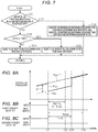
- FIG. 7 is a flow chart illustrating a process routine which is performed to set each determination time, in the first embodiment.
- FIG. 8 are timing charts when each target data has not been input to a second control unit.
- FIG. 9 is a flow chart for explaining a process routine which is performed to set each determination time, in a second embodiment.
- FIG. 10 are timing charts when each target data has not been input to the second control unit.
- a vehicle including a vehicle control system 100 of the present embodiment is schematically shown.
- the vehicle includes a drive motor 10 which is an example of a drive source for the vehicle, and a drive control device 101 for controlling driving of the drive motor 10 .
- the drive control device 101 is one of the components of the control system 100 .
- braking mechanisms 12 are provided for wheels FL, FR, RL, and RR, respectively.
- These braking mechanisms 12 have wheel cylinder 13 a , 13 b , 13 c , and 13 d , respectively, and can give frictional braking forces BPP according to WC pressures Pwc which are the hydraulic pressures in the wheel cylinders 13 a to 13 d to the wheels FL, FR, RL, and RR, respectively.
- the drive system of the vehicle is rear wheel drive, and the driving force output from the drive motor 10 is transmitted to the rear wheels RL and RR via a differential gear 14 . Also, in this vehicle, by controlling the drive motor 10 and an inverter for the drive motor 10 , it is possible to give a regenerative braking force BPR to the rear wheels RL and RR.
- a frictional braking device 20 for controlling the frictional braking forces BPP on the wheels FL, FR, RL, and RR by adjusting the WC pressures Pwc in the wheel cylinders 13 a to 13 d is provided.
- the frictional braking device 20 includes a hydraulic pressure generating device 21 , and a braking actuator 22 provided separately from the hydraulic pressure generating device 21 .
- the braking actuator 22 is an example of a “hydraulic pressure control unit”.
- a first braking control device 102 for controlling the hydraulic pressure generating device 21 and a second braking control device 103 for controlling the braking actuator 22 are provided.
- Each of these braking control devices 102 and 103 is one of the components of the vehicle control system 100 . Further, by operating the hydraulic pressure generating device 21 by the first braking control device 102 , it is possible to adjust the WC pressures Pwc in all wheel cylinders 13 a to 13 d . Also, by operating the braking actuator 22 by the second braking control device 103 , it is possible to separately adjust the WC pressure Pwc in each of the wheel cylinders 13 a to 13 d.
- the hydraulic pressure generating device 21 includes a braking operation member 211 such as a brake pedal, a master cylinder 212 , and two master pistons 213 and 214 disposed inside the master cylinder 212 . Further, inside the master cylinder 212 , two master chambers 215 and 216 are defined by the master pistons 213 and 214 .
- the master chamber 215 is connected to the wheel cylinders 13 a and 13 b for the front wheels, and the master chamber 216 is connected to the wheel cylinders 13 c and 13 d for the rear wheels.
- MC pressures Pmc which are the hydraulic pressures in the master chambers 215 and 216 increase if the master pistons 213 and 214 are displaced to the pressurization side (the left in the drawings), and decrease if the master pistons 213 and 214 are displaced to the depressurization side (the right in the drawings).
- an operation unit 217 for operating to displace the master pistons 213 and 214 inside the master cylinder 212 is provided.
- by adjusting the MC pressures Pmc by the operation of the operation unit 217 it is possible to adjust the WC pressure Pwc in each of the wheel cylinders 13 a to 13 d .
- an operation amount sensor SE 1 for detecting the operation amount on the braking operation member 211 is provided, and the output signal from the operation amount sensor SE 1 is input to the first braking control device 102 .
- the braking actuator 22 includes a front wheel system brake unit 221 disposed between the master chamber 215 and the wheel cylinders 13 a and 13 b for the front wheels, and a rear wheel system brake unit 222 disposed between the master chamber 216 and the wheel cylinders 13 c and 13 d for the rear wheels.
- a front wheel system brake unit 221 By operating the front wheel system brake unit 221 , it is possible to generate a differential pressure between the insides of the wheel cylinders 13 a and 13 b for the front wheels and the master chamber 215 , such that the WC pressure Pwc in the wheel cylinders 13 a and 13 b for the front wheels becomes higher than the MC pressure Pmc in the master chamber 215 .
- the rear wheel system brake unit 222 by operating the rear wheel system brake unit 222 , it is possible to generate a differential pressure between the insides of the wheel cylinders 13 c and 13 d for the rear wheels and the master chamber 216 , such that the WC pressure Pwc in the wheel cylinders 13 c and 13 d for the rear wheels becomes higher than the MC pressure Pmc in the master chamber 216 .
- FIG. 3 the operations of the hydraulic pressure generating device 21 and the braking actuator 22 for decelerating the vehicle by giving a braking force will be described. Also, in FIG. 3 , the transition of the WC pressure Pwc in the wheel cylinders 13 a and 13 b for the front wheels is shown.
- the drive motor 10 is connected to the rear wheels RL and RR and drives them. For this reason, during braking of the vehicle, the regenerative braking force BPR is given to the rear wheels, but the regenerative braking force BPR is not given to the front wheels FL and FR. Therefore, at the early stage of braking of the vehicle, in order not to decrease the stability of the behavior of the vehicle, as shown in FIG. 3 , first, by the operation of the braking actuator 22 , the differential pressure DP between the insides of the wheel cylinders 13 a and 13 b for the front wheels and the master chamber 215 is increased, whereby the WC pressure Pwc in the wheel cylinders 13 a and 13 b for the front wheels increases.
- the braking actuator 22 operates so as not to increase the WC pressure Pwc in the wheel cylinders 13 c and 13 d for the rear wheels. Further, from a timing t 11 when the WC pressure Pwc in the wheel cylinders 13 a and 13 b for the front wheels has increased to an extent by the operation of the braking actuator 22 , the operation of the operation unit 217 of the hydraulic pressure generating device 21 is started. If the operation of the operation unit 217 is started as described above, the braking actuator 22 operates to hold the differential pressure DP between the master chamber 215 and the insides of the wheel cylinders 13 a and 13 b for the front wheels. Further, if the MC pressure Pmc in each of the master chambers 215 and 216 becomes higher by the operation of the operation unit 217 , the WC pressure Pwc in each of the wheel cylinders 13 a to 13 d increases.
- the control system 100 of the present embodiment includes a control device 104 for automatic driving for generally controlling the vehicle to make the vehicle perform automatic driving.
- a first communication bus 111 which is an example of a first communication system
- a second communication bus 112 which is an example of a second communication system different from the first communication system are provided.
- each of the individual control devices 101 to 104 which constitute the control system 100 is electrically connected to the first communication bus 111 , and is electrically connected to the second communication bus 112 .
- the individual control devices 101 to 104 can perform both of outputting a variety of data to the first communication bus 111 and outputting a variety of data to the second communication bus 112 .
- the individual control devices 101 to 104 can perform both of receiving a variety of data through the first communication bus 111 and receiving a variety of data through the second communication bus 112 .
- the first braking control device 102 since the operation amount sensor SE 1 is electrically connected to the first braking control device 102 , the first braking control device 102 computes a required braking force BPT on the basis of the output signal from the operation amount sensor SE 1 . Further, in the case of increasing the WC pressures Pwc in the wheel cylinders 13 a to 13 d by the operation of the braking actuator 22 , the first braking control device 102 outputs target data related to target values for the WC pressures Pwc, i.e. differential-pressure target values DPTr which are target values for the differential pressures DP between the master chambers 215 and 216 and the wheel cylinders 13 a to 13 d .
- DPTr differential-pressure target values
- the first braking control device 102 outputs the target data to both of the first communication bus 111 and the second communication bus 112 .
- the target data is input through the first communication bus 111
- the target data is input through the second communication bus 112 .
- the second braking control device 103 controls the operation of the braking actuator 22 on the basis of the target data input through at least one communication bus of the individual communication buses 111 and 112 .
- the required braking force BPT is calculated by the control device 104 for automatic driving.
- the control device 104 for automatic driving calculates the target value for the WC pressure Pwc on the basis of the required braking force BPT, and outputs the target data related to the target value to both of the first communication bus 111 and the second communication bus 112 .
- the second braking control device 103 can control the operation of the braking actuator 22 on the basis of the target data input through at least one communication bus of the individual communication buses 111 and 112 .
- first target data Tr 1 target data which the first braking control device 102 or the control device 104 for automatic driving outputs to the first communication bus 111 in order to operate the braking actuator 22
- second target data Tr 2 target data which it outputs to the second communication bus 112
- the temporal length of the second cycle CLC 2 is N times the temporal length of the first cycle CLC 1 (N is an integer of 2 or greater, for example, 2).
- the transition of the differential-pressure target value DPTr which is calculated by the first braking control device 102 is shown.
- the case where the differential-pressure target value DPTr is equal to a target hydraulic-pressure PwcTr which is a target value for the WC pressures Pwc in the wheel cylinders 13 a to 13 d is shown.
- the transition of the first target data Tr 1 which is input to the second braking control device 103 through the first communication bus 111 is shown by a thick solid line
- the transition of the second target data Tr 2 which is input to the second braking control device 103 through the second communication bus 112 is shown by a broken line.
- the information amount of the second target data Tr 2 may be the same as that of the first target data Tr 1 , or may be smaller than the information amount of the first target data Tr 1 .
- the second braking control device 103 includes a second control unit 121 for controlling the operation of the braking actuator 22 on the basis of at least one data of the first target data Tr 1 and the second target data Tr 2 input through the communication buses 111 and 112 .
- the second control unit 121 controls the operation of the braking actuator 22 on the basis of the differential-pressure target value DPTr represented by the first target data Tr 1 .
- the second control unit 121 controls the operation of the braking actuator 22 on the basis of the differential-pressure target value DPTr represented by the second target data Tr 2 .
- the second control unit 121 acts as an example of a “control unit” for controlling the braking actuator 22 which is an example of the hydraulic pressure control unit.
- the second control unit 121 cannot control the operation of the braking actuator 22 .
- a differential pressure DP has been generated between the master chambers 215 and 216 and the wheel cylinders 13 a to 13 d by the operation of the braking actuator 22 .
- the WC pressure Pwc decreases.
- the first braking control device 102 includes a target value calculation unit 131 , an input monitoring unit 132 , a determination time changing unit 133 , and a first control unit 134 , as functional units for controlling the frictional braking device 20 .
- the target value calculation unit 131 calculates a target value for operating the frictional braking device 20 .
- the target value calculation unit 131 obtains a required frictional braking force BPPT by subtracting the sum of the regenerative braking forces BPR which the drive motor 10 is giving to the rear wheels RL and RR from the required braking force BPT based on the output signal from the operation amount sensor SE 1 .
- the target value calculation unit 131 calculates the target hydraulic-pressure PwcTr which is the target value for the WC pressures Pwc in the wheel cylinders 13 a to 13 d , on the basis of the calculated required frictional braking force BPPT.
- the target value calculation unit 131 calculates a differential-pressure target value DPTr which is a target value for the differential pressures DP between the master chambers 215 and 216 and the wheel cylinders 13 a to 13 d , and an MC pressure target value PmcTr which is a target value for the MC pressure Pmc in the master chambers 215 and 216 , on the basis of the calculated target hydraulic-pressure PwcTr.
- the target value calculation unit 131 outputs WC pressure target data related to the target hydraulic-pressure PwcTr and the differential-pressure target value DPTr calculated, as the first target data Tr 1 , to the first communication bus 111 , and generates the second target data Tr 2 from the WC pressure target data, and outputs the second target data Tr 2 to the second communication bus 112 . Furthermore, the target value calculation unit 131 outputs the calculated MC pressure target value PmcTr to the first control unit 134 .
- the input monitoring unit 132 monitors whether the first target data Tr 1 is being input to the second braking control device 103 through the first communication bus 111 , and monitors whether the second target data Tr 2 is being input to the second braking control device 103 through the second communication bus 112 . Further, in the case of determining that both data of the first target data Tr 1 and the second target data Tr 2 are not input to the second braking control device 103 , the input monitoring unit 132 outputs an abnormality signal to the first control unit 134 .
- the determination time changing unit 133 In the case of changing determination times TM 1 Th and TM 2 Th to be used for monitoring of the input monitoring unit 13 , the determination time changing unit 133 outputs the changed determination times TM 1 Th and TM 2 Th to the input monitoring unit 132 .
- the determination times TM 1 Th and TM 2 Th will be further described below.
- the first control unit 134 controls the operation of the hydraulic pressure generating device 21 on the basis of the MC pressure target value PmcTr input from the target value calculation unit 131 . Also, if the abnormality signal is input from the input monitoring unit 132 , the first control unit 134 performs a backup process of restoring the braking force by the operation of the hydraulic pressure generating device 21 in order to compensate the decrease of the WC pressure Pwc attributable to the stop of the operation of the braking actuator 22 , i.e. the decrease of the braking force on the wheels FL, FR, RL, and RR. In this case, in the backup process, the first control unit 134 controls the operation of the hydraulic pressure generating device 21 on the basis of the target hydraulic-pressure PwcTr, not on the basis of the MC pressure target value PmcTr.
- the input monitoring unit 132 determines whether the first target data Tr 1 is being input to the second braking control device 103 through the first communication bus 111 (STEP S 11 ). In the case of determining that the first target data Tr 1 is being input to the second braking control device 103 (YES in STEP S 11 ), the input monitoring unit 132 resets a first duration TM 1 to “0” (STEP S 12 ).
- the first duration TM 1 is the duration of the state where the first target data Tr 1 is not being input to the second braking control device 103 .
- the first duration TM 1 can also be referred to as the elapsed time from the time point when it is detected that the first target data Tr 1 is not being input to the second braking control device 103 .
- the input monitoring unit 132 sets “OFF” in a first non-input flag FLG 1 to be described below (STEP S 13 ), and then advances the process to STEP S 17 to be described below.
- the input monitoring unit 132 updates the first duration TM 1 (STEP S 14 ). Subsequently, the input monitoring unit 132 determines whether the updated first duration TM 1 is equal to or longer than a first determination time TM 1 Th (STEP S 15 ).
- the first determination time TM 1 Th is a determination value for determining whether to determine that the first target data Tr 1 is in the non-input state where it is not being input to the second braking control device 103 .
- the first duration TM 1 is equal to or longer than the first determination time TM 1 Th, it is possible to determine that the first target data Tr 1 is in the non-input state; however, in the case where the first duration TM 1 is shorter than the first determination time TM 1 Th, it is impossible to determine that the first target data Tr 1 is in the non-input state.
- the first determination time TM 1 Th becomes equal to the time corresponding to M-number of first cycles CLC 1 (M is an integer of 2 or greater, for example, 4). For this reason, when the first target data Tr 1 has not consecutively been input to the second braking control device 103 M-number of times, the first duration TM 1 becomes equal to or longer than the first determination time TM 1 Th, so it is possible to determine that the first target data Tr 1 is in the non-input state.
- the input monitoring unit 132 sets “ON” in the first non-input flag FLG 1 (STEP S 16 ), and advances the process to the next STEP S 17 .
- the first non-input flag FLG 1 is a flag which is set to “ON” if it is possible to determine that the first target data Tr 1 is in the non-input state, and is set to “OFF” if it is not possible to determine that the first target data Tr 1 is in the non-input state.
- the input monitoring unit 132 advances the process to the next STEP S 17 , without performing the process of STEP S 16 .
- the input monitoring unit 132 determines whether the second target data Tr 2 is being input to the second braking control device 103 through the second communication bus 112 . In the case of determining that the second target data Tr 2 is being input to the second braking control device 103 (YES in STEP S 17 ), the input monitoring unit 132 resets a second duration TM 2 to “0” (STEP S 18 ). The second duration TM 2 is the duration of the state where the second target data Tr 2 is not being input to the second braking control device 103 . Subsequently, the input monitoring unit 132 sets “OFF” in a second non-input flag FLG 2 to be described below (STEP S 19 ), and then temporarily ends the present process routine.
- the input monitoring unit 132 updates the second duration TM 2 (STEP S 20 ). Subsequently, the input monitoring unit 132 determines whether the second duration TM 2 is equal to or longer than a second determination time TM 2 Th (STEP S 21 ).
- the second determination time TM 2 Th is a determination value for determining whether to determine that the second target data Tr 2 is in the non-input state where it is not being input to the second braking control device 103 .
- the second duration TM 2 is equal to or longer than the second determination time TM 2 Th, it is possible to determine that the second target data Tr 2 is in the non-input state; whereas, in the case where the second duration TM 2 is shorter than the second determination time TM 2 Th, it is impossible to determine that the second target data Tr 2 is in the non-input state.
- the second determination time TM 2 Th becomes equal to the time corresponding to M-number of second cycles CLC 2 (M is an integer of 2 or greater, for example, 4). For this reason, when the second target data Tr 2 has not consecutively been input to the second braking control device 103 M-number of times, the second duration TM 2 becomes equal to or longer than the second determination time TM 2 Th, so it is possible to determine that the second target data Tr 2 is in the non-input state.
- the input monitoring unit 132 sets “ON” in the second non-input flag FLG 2 (STEP S 22 ), and temporarily ends the present process routine.
- the second non-input flag FLG 2 is a flag which is set to “ON” if it is possible to determine that the second target data Tr 2 is in the non-input state, and is set to “OFF” if it is not possible to determine that the second target data Tr 2 is in the non-input state.
- the input monitoring unit 132 temporarily ends the present process routine, without performing the process of STEP S 22 .
- the input monitoring unit 132 outputs the abnormality signal to the first control unit 134 .
- the determination time changing unit 133 determines whether “OFF” has been set in both of the first non-input flag FLG 1 and the second non-input flag FLG 2 (STEP S 31 ). In the case where “OFF” has been set in both of the first non-input flag FLG 1 and the second non-input flag FLG 2 (YES in STEP S 31 ), the determination time changing unit 133 substitutes the first determination time TM 1 Th with a reference determination time TM 1 B, and substitutes the second determination time TM 2 Th with a reference determination time TM 2 B (STEP S 32 ).
- the reference determination time TM 1 B is the first determination time TM 1 Th when it is not determined that the first target data Tr 1 is in the non-input state, and is equal to the time corresponding to M-number of first cycles CLC 1 .
- the reference determination time TM 2 B is the second determination time TM 2 Th when it is not determined that the second target data Tr 2 is in the non-input state, and is equal to the time corresponding to M-number of second cycles CLC 2 .
- the determination time changing unit 133 temporarily ends the present process routine.
- the determination time changing unit 133 determines whether “ON” has been set in the first non-input flag FLG 1 (STEP S 33 ). In the case where “OFF” has been set in the first non-input flag FLG 1 , it is possible to determine that “ON” has been set in the second non-input flag FLG 2 .
- the determination time changing unit 133 substitutes the first determination time TM 1 Th with a shortened determination time TM 1 A shorter than the reference determination time TM 1 B (STEP S 34 ).
- This shortened determination time TM 1 A is equal to, for example, the time corresponding to L-number of first cycles CLC 1 (L is an integer equal to or greater than 1 and smaller than M, for example, 2).
- L is an integer equal to or greater than 1 and smaller than M, for example, 2).
- the determination time changing unit 133 temporarily ends the present process routine.
- the determination time changing unit 133 substitutes the second determination time TM 2 Th with a shortened determination time TM 2 A shorter than the reference determination time TM 2 B (STEP S 35 ).
- This shortened determination time TM 2 A is equal to, for example, the time corresponding to L-number of second cycles CLC 2 .
- the determination time changing unit 133 temporarily ends the present process routine.
- both of the first target data Tr 1 and the second target data Tr 2 are input to the second braking control device 103 .
- the differential pressures DP between the wheel cylinders 13 a to 13 d and the master chambers 215 and 216 are adjusted so as to approach the differential-pressure target value DPTr based on the first target data Tr 1 .
- the differential pressure DP decreases. In the example shown in FIG. 8 , the differential pressure DP becomes equal to “0”.
- the first determination time TM 1 Th is equal to the reference determination time TM 1 B
- the second determination time TM 2 Th is equal to the reference determination time TM 2 B.
- the state where the second target data Tr 2 is not being input to the second braking control device 103 has continued from the first timing t 21 .
- the second determination time TM 2 Th is shortened from the reference determination time TM 2 B to the shortened determination time TM 2 A.
- the timing when the elapsed time from the first timing t 21 when the second target data Tr 2 was not input to the second braking control device 103 reaches the reference determination time TM 2 B is referred to as a fourth timing t 24 .
- TM 2 Th TM 2 A
- the backup process is started. Then, by the operation of the hydraulic pressure generating device 21 according to the backup process, the MC pressure Pmc in each of the master chambers 215 and 216 increases. According to the increase of the MC pressure Pmc, the WC pressure Pwc in each of the wheel cylinders 13 a to 13 d increases. Therefore, in the case where the WC pressure Pwc, i.e. the braking force on the wheels FL, FR, RL, and RR decreases by stop of the operation of the braking actuator 22 , it is possible to early restore the braking force by early starting the backup process.
- the WC pressure Pwc i.e. the braking force on the wheels FL, FR, RL, and RR decreases by stop of the operation of the braking actuator 22 .
- the data communication method using the second communication bus 112 the method of changing the second determination time TM 2 Th in the case of determining that the first target data Tr 1 has become the non-input state, and so on are different from the first embodiment. Therefore, in the following description, the parts different from the first embodiment will be mainly described, and components identical or corresponding to those of the first embodiment are denoted by the same reference symbols, and a repetitive description will not be made.
- the second target data Tr 2 is output from the first braking control device 102 or the control device 104 for automatic driving every second cycle CLC 2 .
- data different from the second target data Tr 2 also is input through the second communication bus 112 .
- Such data will be referred to as “first different data”.
- the determination time changing unit 133 determines whether “OFF” has been set in both of the first non-input flag FLG 1 and the second non-input flag FLG 2 (STEP S 41 ). In the case where “OFF” has been set in both non-input flags FLG 1 and FLG 2 (YES in STEP S 41 ), the determination time changing unit 133 substitutes the first determination time TM 1 Th with a reference determination time TM 1 B, and substitutes the second determination time TM 2 Th with a reference determination time TM 2 B (STEP S 42 ). Thereafter, the determination time changing unit 133 temporarily ends the present process routine.
- the determination time changing unit 133 determines whether “ON” has been set in the first non-input flag FLG 1 (STEP S 43 ). In the case where “OFF” has been set in the first non-input flag FLG 1 (NO in STEP S 43 ), the determination time changing unit 133 substitutes the first determination time TM 1 Th with the shortened determination time TM 1 A (STEP S 44 ), and then temporarily ends the present process routine.
- the determination time changing unit 133 substitutes the second determination time TM 2 Th with the shortened determination time TM 1 A shorter than the reference determination time TM 2 B (STEP S 45 ). Thereafter, the determination time changing unit 133 temporarily ends the present process routine.
- an alternate long and short dash line indicates the transition of the target hydraulic-pressure PwcTr which is the target value for the WC pressures Pwc
- a solid line indicates the transition of the actual WC pressure Pwc
- a broken line indicates the transition of the MC pressure Pmc in the master chamber 215 or 216 .
- the first determination time TM 1 Th is equal to the reference determination time TM 1 B
- the second determination time TM 2 Th is equal to the reference determination time TM 2 B.
- TM 1 B the first determination time
- the second determination time TM 2 Th is changed from the reference determination time TM 2 B to the shortened determination time TM 1 A.
- time measurement may start from the time point when inputting of the first target data Tr 1 to the second braking control device 103 stops, and if the measurement time which is the time which is measured reaches the second determination time TM 2 Th, it may be determined that the second target data Tr 2 is in the non-input state.
- the measurement time is reset to “0”.
- the length of the second cycle CLC 2 may be equal to the length of the first cycle CLC 1 .
- the reference determination time TM 2 B may be set to be equal to the reference determination time TM 1 B.
- the length of the second cycle CLC 2 may be set to be longer than the length of the first cycle CLC 1 .
- the reference determination time TM 2 B may be set to be equal to the reference determination time TM 1 B, or may be set to be longer than the reference determination time TM 1 B.
- the shortened determination times TM 1 A and TM 2 A are fixed to predetermined values; however, the shortened determination times TM 1 A and TM 2 A may be changed according to parameters.
- the differential pressure DP attributable to the operation of the braking actuator 22 increases, the decrease amount of the WC pressure Pwc attributable to stop of the operation of the braking actuator 22 increases.
- the decrease amount of the WC pressure Pwc increases as described above, it is more required to restore the WC pressure Pwc, and it is desired to early restore the WC pressure Pwc.
- the shortened determination time TM 1 A may be calculated using the following relational expression (Expression 1), and the shortened determination time TM 2 A may be calculated using a relational expression (Expression 2).
- the relational expressions (Expression 1) and (Expression 2) is a determination time shortening amount, and it is preferable to increase the shortening amount Y as the differential pressure DP attributable to the operation of the braking actuator 22 increases.
- TM 1 A TM 1 B ⁇ Y (Expression 1)
- TM 2 A TM 2 B ⁇ Y (Expression 2)
- the determination times TM 1 Th and TM 2 Th are very short, regardless of whether the decrease amount of the WC pressure Pwc attributable to stop of the operation of the braking actuator 22 is large or small.
- the determination times TM 1 Th and TM 2 Th shorten, the accuracy of determination on whether each of the target data Tr 1 and Tr 2 is in the non-input state decreases.
- the shortening amount Y is set to be small, and the determination times TM 1 Th and TM 2 Th are set not to be too short. According to this, it is possible to implement early performance of the backup process while suppressing decrease of the accuracy of determination on whether the target data is in the non-input state.
- another control device (for example, the control device 104 for automatic driving) different from the first braking control device 102 and the second braking control device 103 may be configured to include the input monitoring unit 132 and the determination time changing unit 133 .
- a brake device capable of increasing the braking force on the wheels FL, FR, RL, and RR without increasing the WC pressures Pwc in the wheel cylinders 13 a to 13 d may be provided separately from the frictional braking device 20 .
- another brake device provided separately from the frictional braking device 20 may be operated to perform the backup process of restoring the braking force.
- a regenerative braking device capable of giving a regenerative braking force to the wheels can be taken.
- the electric parking device can be taken.
- the backup process may be a process including a notifying process of requesting the driver of the vehicle to increase the braking operation amount in order to urge the driver of the vehicle to restore the braking force on the wheels FL, FR, RL, and RR.
- the determination time changing unit should perform a time shortening process of shortening the first determination time in the case where it is determined by the input monitoring unit that the second target data is in the non-input state, as compared to the case where it is not determined that the second target data is in the non-input state.
Landscapes
- Engineering & Computer Science (AREA)
- Transportation (AREA)
- Mechanical Engineering (AREA)
- Regulating Braking Force (AREA)
Abstract
Description
TM1A=TM1B−Y (Expression 1)
TM2A=TM2B−Y (Expression 2)
Claims (8)
Applications Claiming Priority (4)
| Application Number | Priority Date | Filing Date | Title |
|---|---|---|---|
| JP2017-003607 | 2017-01-12 | ||
| JPJP2017-003607 | 2017-01-12 | ||
| JP2017003607A JP6627786B2 (en) | 2017-01-12 | 2017-01-12 | Vehicle control system |
| PCT/JP2018/000366 WO2018131615A1 (en) | 2017-01-12 | 2018-01-10 | Vehicle control system |
Publications (2)
| Publication Number | Publication Date |
|---|---|
| US20190381978A1 US20190381978A1 (en) | 2019-12-19 |
| US11180123B2 true US11180123B2 (en) | 2021-11-23 |
Family
ID=62839882
Family Applications (1)
| Application Number | Title | Priority Date | Filing Date |
|---|---|---|---|
| US16/476,702 Active 2038-07-03 US11180123B2 (en) | 2017-01-12 | 2018-01-10 | Vehicle control system |
Country Status (5)
| Country | Link |
|---|---|
| US (1) | US11180123B2 (en) |
| JP (1) | JP6627786B2 (en) |
| CN (1) | CN110167803B (en) |
| DE (1) | DE112018000367B4 (en) |
| WO (1) | WO2018131615A1 (en) |
Families Citing this family (1)
| Publication number | Priority date | Publication date | Assignee | Title |
|---|---|---|---|---|
| JP7389067B2 (en) | 2021-01-15 | 2023-11-29 | トヨタ自動車株式会社 | Vehicle brake system |
Citations (3)
| Publication number | Priority date | Publication date | Assignee | Title |
|---|---|---|---|---|
| US20070188018A1 (en) * | 2006-02-14 | 2007-08-16 | Reuter David F | Brake-by-wire braking system with hydraulic fail-safe |
| US20160041862A1 (en) * | 2012-03-16 | 2016-02-11 | Infineon Technologies Ag | Method and system for timeout monitoring |
| JP2016144178A (en) | 2015-02-05 | 2016-08-08 | 株式会社デンソー | Communication device |
Family Cites Families (8)
| Publication number | Priority date | Publication date | Assignee | Title |
|---|---|---|---|---|
| DE19937159B4 (en) * | 1999-08-06 | 2019-03-21 | Robert Bosch Gmbh | Electrically controlled braking system |
| JP4479640B2 (en) * | 2005-10-20 | 2010-06-09 | トヨタ自動車株式会社 | Brake control device |
| JP2008055992A (en) * | 2006-08-30 | 2008-03-13 | Hitachi Ltd | Brake control device |
| WO2011089727A1 (en) * | 2010-01-25 | 2011-07-28 | トヨタ自動車株式会社 | Braking control device and braking device |
| WO2012049747A1 (en) * | 2010-10-13 | 2012-04-19 | トヨタ自動車株式会社 | Brake device for vehicle and control device |
| JP5961513B2 (en) | 2012-09-28 | 2016-08-02 | 日立オートモティブシステムズ株式会社 | Vehicle control device and brake control device |
| JP2014169039A (en) * | 2013-03-05 | 2014-09-18 | Hitachi Automotive Systems Ltd | Brake control device |
| US9669809B2 (en) * | 2013-05-13 | 2017-06-06 | Toyota Jidosha Kabushiki Kaisha | Brake control device for vehicle |
-
2017
- 2017-01-12 JP JP2017003607A patent/JP6627786B2/en active Active
-
2018
- 2018-01-10 CN CN201880006318.7A patent/CN110167803B/en active Active
- 2018-01-10 US US16/476,702 patent/US11180123B2/en active Active
- 2018-01-10 DE DE112018000367.1T patent/DE112018000367B4/en active Active
- 2018-01-10 WO PCT/JP2018/000366 patent/WO2018131615A1/en not_active Ceased
Patent Citations (3)
| Publication number | Priority date | Publication date | Assignee | Title |
|---|---|---|---|---|
| US20070188018A1 (en) * | 2006-02-14 | 2007-08-16 | Reuter David F | Brake-by-wire braking system with hydraulic fail-safe |
| US20160041862A1 (en) * | 2012-03-16 | 2016-02-11 | Infineon Technologies Ag | Method and system for timeout monitoring |
| JP2016144178A (en) | 2015-02-05 | 2016-08-08 | 株式会社デンソー | Communication device |
Non-Patent Citations (1)
| Title |
|---|
| International Search Report dated Apr. 17, 2018 in PCT/JP2018/000366 filed on Jan. 10, 2018. |
Also Published As
| Publication number | Publication date |
|---|---|
| DE112018000367B4 (en) | 2023-07-06 |
| JP6627786B2 (en) | 2020-01-08 |
| CN110167803B (en) | 2021-04-13 |
| WO2018131615A1 (en) | 2018-07-19 |
| DE112018000367T5 (en) | 2019-09-26 |
| JP2018111423A (en) | 2018-07-19 |
| CN110167803A (en) | 2019-08-23 |
| US20190381978A1 (en) | 2019-12-19 |
Similar Documents
| Publication | Publication Date | Title |
|---|---|---|
| US9776607B2 (en) | Fault-tolerant redundant by-wire brake system | |
| CN107792032B (en) | Brake-by-wire system | |
| US10065613B2 (en) | Brake system for vehicles | |
| CN110505988B (en) | Motor vehicle hydraulic brake system and control unit system | |
| KR102652162B1 (en) | Braking apparatus of vehicle and control method thereof | |
| US10239510B2 (en) | Method for controlling a hydraulic brake system of a motor vehicle | |
| US8812211B2 (en) | Adapting a braking process | |
| CN107792041B (en) | Brake-by-wire system | |
| JP2015509460A (en) | Method for operating a braking device | |
| KR101405189B1 (en) | Braking system for hybrid vehicle and control method for the same | |
| US20150197229A1 (en) | Electrohydraulic Motor Vehicle Brake System and Method for Operating the Same | |
| JP2020521666A (en) | Auxiliary deceleration using electronic parking brake in a fully integrated braking system | |
| JPH1178819A (en) | Vehicle braking system | |
| US11180123B2 (en) | Vehicle control system | |
| CN104884317A (en) | Control device for a brake system of a vehicle, and method for operating a brake system of a vehicle | |
| JP2025527847A (en) | Method for operating a brake system and control device configured to carry out said method | |
| CN117302128A (en) | Anti-lock braking methods, vehicles and storage media | |
| JP6466240B2 (en) | Braking device for vehicle | |
| CN111791863B (en) | Braking force generator and method of operation | |
| JP2001278018A (en) | Method for controlling the output of an electromechanical brake system of a motor vehicle | |
| JP2002240692A (en) | Electric brake system and computer program | |
| US12054129B2 (en) | Method for operating a vehicle brake system, control unit, and vehicle | |
| KR100751220B1 (en) | Sensor failure detection method and device | |
| CN109476299B (en) | Vehicle brake control device | |
| US20250091560A1 (en) | Hydraulic boost failure compensation system |
Legal Events
| Date | Code | Title | Description |
|---|---|---|---|
| AS | Assignment |
Owner name: ADVICS CO., LTD., JAPAN Free format text: ASSIGNMENT OF ASSIGNORS INTEREST;ASSIGNORS:ISHIDA, YASUHITO;YAMAMOTO, TAKAYUKI;SIGNING DATES FROM 20190614 TO 20190619;REEL/FRAME:049701/0438 |
|
| FEPP | Fee payment procedure |
Free format text: ENTITY STATUS SET TO UNDISCOUNTED (ORIGINAL EVENT CODE: BIG.); ENTITY STATUS OF PATENT OWNER: LARGE ENTITY |
|
| STPP | Information on status: patent application and granting procedure in general |
Free format text: NON FINAL ACTION MAILED |
|
| STPP | Information on status: patent application and granting procedure in general |
Free format text: RESPONSE TO NON-FINAL OFFICE ACTION ENTERED AND FORWARDED TO EXAMINER |
|
| STPP | Information on status: patent application and granting procedure in general |
Free format text: NOTICE OF ALLOWANCE MAILED -- APPLICATION RECEIVED IN OFFICE OF PUBLICATIONS |
|
| STPP | Information on status: patent application and granting procedure in general |
Free format text: PUBLICATIONS -- ISSUE FEE PAYMENT VERIFIED |
|
| STCF | Information on status: patent grant |
Free format text: PATENTED CASE |
|
| MAFP | Maintenance fee payment |
Free format text: PAYMENT OF MAINTENANCE FEE, 4TH YEAR, LARGE ENTITY (ORIGINAL EVENT CODE: M1551); ENTITY STATUS OF PATENT OWNER: LARGE ENTITY Year of fee payment: 4 |