US11173810B2 - Seat opening concealment structure - Google Patents
Seat opening concealment structure Download PDFInfo
- Publication number
- US11173810B2 US11173810B2 US16/861,278 US202016861278A US11173810B2 US 11173810 B2 US11173810 B2 US 11173810B2 US 202016861278 A US202016861278 A US 202016861278A US 11173810 B2 US11173810 B2 US 11173810B2
- Authority
- US
- United States
- Prior art keywords
- wall
- seat
- face portion
- section
- opening
- Prior art date
- Legal status (The legal status is an assumption and is not a legal conclusion. Google has not performed a legal analysis and makes no representation as to the accuracy of the status listed.)
- Expired - Fee Related
Links
Images


Classifications
-
- B—PERFORMING OPERATIONS; TRANSPORTING
- B60—VEHICLES IN GENERAL
- B60N—SEATS SPECIALLY ADAPTED FOR VEHICLES; VEHICLE PASSENGER ACCOMMODATION NOT OTHERWISE PROVIDED FOR
- B60N2/00—Seats specially adapted for vehicles; Arrangement or mounting of seats in vehicles
- B60N2/02—Seats specially adapted for vehicles; Arrangement or mounting of seats in vehicles the seat or part thereof being movable, e.g. adjustable
- B60N2/04—Seats specially adapted for vehicles; Arrangement or mounting of seats in vehicles the seat or part thereof being movable, e.g. adjustable the whole seat being movable
- B60N2/10—Seats specially adapted for vehicles; Arrangement or mounting of seats in vehicles the seat or part thereof being movable, e.g. adjustable the whole seat being movable tiltable
-
- B—PERFORMING OPERATIONS; TRANSPORTING
- B60—VEHICLES IN GENERAL
- B60N—SEATS SPECIALLY ADAPTED FOR VEHICLES; VEHICLE PASSENGER ACCOMMODATION NOT OTHERWISE PROVIDED FOR
- B60N3/00—Arrangements or adaptations of other passenger fittings, not otherwise provided for
- B60N3/06—Arrangements or adaptations of other passenger fittings, not otherwise provided for of footrests
- B60N3/063—Arrangements or adaptations of other passenger fittings, not otherwise provided for of footrests with adjustment systems
-
- B—PERFORMING OPERATIONS; TRANSPORTING
- B60—VEHICLES IN GENERAL
- B60N—SEATS SPECIALLY ADAPTED FOR VEHICLES; VEHICLE PASSENGER ACCOMMODATION NOT OTHERWISE PROVIDED FOR
- B60N2/00—Seats specially adapted for vehicles; Arrangement or mounting of seats in vehicles
- B60N2/80—Head-rests
- B60N2/806—Head-rests movable or adjustable
- B60N2/838—Tiltable
-
- B—PERFORMING OPERATIONS; TRANSPORTING
- B60—VEHICLES IN GENERAL
- B60N—SEATS SPECIALLY ADAPTED FOR VEHICLES; VEHICLE PASSENGER ACCOMMODATION NOT OTHERWISE PROVIDED FOR
- B60N2/00—Seats specially adapted for vehicles; Arrangement or mounting of seats in vehicles
- B60N2/02—Seats specially adapted for vehicles; Arrangement or mounting of seats in vehicles the seat or part thereof being movable, e.g. adjustable
- B60N2/0224—Non-manual adjustments, e.g. with electrical operation
- B60N2/02246—Electric motors therefor
-
- B—PERFORMING OPERATIONS; TRANSPORTING
- B60—VEHICLES IN GENERAL
- B60N—SEATS SPECIALLY ADAPTED FOR VEHICLES; VEHICLE PASSENGER ACCOMMODATION NOT OTHERWISE PROVIDED FOR
- B60N2/00—Seats specially adapted for vehicles; Arrangement or mounting of seats in vehicles
- B60N2/02—Seats specially adapted for vehicles; Arrangement or mounting of seats in vehicles the seat or part thereof being movable, e.g. adjustable
- B60N2/04—Seats specially adapted for vehicles; Arrangement or mounting of seats in vehicles the seat or part thereof being movable, e.g. adjustable the whole seat being movable
- B60N2/14—Seats specially adapted for vehicles; Arrangement or mounting of seats in vehicles the seat or part thereof being movable, e.g. adjustable the whole seat being movable rotatable, e.g. to permit easy access
- B60N2/143—Seats specially adapted for vehicles; Arrangement or mounting of seats in vehicles the seat or part thereof being movable, e.g. adjustable the whole seat being movable rotatable, e.g. to permit easy access taking a position opposite to the original one
-
- B—PERFORMING OPERATIONS; TRANSPORTING
- B60—VEHICLES IN GENERAL
- B60N—SEATS SPECIALLY ADAPTED FOR VEHICLES; VEHICLE PASSENGER ACCOMMODATION NOT OTHERWISE PROVIDED FOR
- B60N2/00—Seats specially adapted for vehicles; Arrangement or mounting of seats in vehicles
- B60N2/02—Seats specially adapted for vehicles; Arrangement or mounting of seats in vehicles the seat or part thereof being movable, e.g. adjustable
- B60N2/22—Seats specially adapted for vehicles; Arrangement or mounting of seats in vehicles the seat or part thereof being movable, e.g. adjustable the back-rest being adjustable
- B60N2/2222—Seats specially adapted for vehicles; Arrangement or mounting of seats in vehicles the seat or part thereof being movable, e.g. adjustable the back-rest being adjustable the back-rest having two or more parts
-
- B—PERFORMING OPERATIONS; TRANSPORTING
- B60—VEHICLES IN GENERAL
- B60N—SEATS SPECIALLY ADAPTED FOR VEHICLES; VEHICLE PASSENGER ACCOMMODATION NOT OTHERWISE PROVIDED FOR
- B60N2/00—Seats specially adapted for vehicles; Arrangement or mounting of seats in vehicles
- B60N2/24—Seats specially adapted for vehicles; Arrangement or mounting of seats in vehicles for particular purposes or particular vehicles
- B60N2/32—Seats specially adapted for vehicles; Arrangement or mounting of seats in vehicles for particular purposes or particular vehicles convertible for other use
- B60N2/34—Seats specially adapted for vehicles; Arrangement or mounting of seats in vehicles for particular purposes or particular vehicles convertible for other use into a bed
-
- B—PERFORMING OPERATIONS; TRANSPORTING
- B60—VEHICLES IN GENERAL
- B60N—SEATS SPECIALLY ADAPTED FOR VEHICLES; VEHICLE PASSENGER ACCOMMODATION NOT OTHERWISE PROVIDED FOR
- B60N2/00—Seats specially adapted for vehicles; Arrangement or mounting of seats in vehicles
- B60N2/58—Seat coverings
-
- B—PERFORMING OPERATIONS; TRANSPORTING
- B60—VEHICLES IN GENERAL
- B60N—SEATS SPECIALLY ADAPTED FOR VEHICLES; VEHICLE PASSENGER ACCOMMODATION NOT OTHERWISE PROVIDED FOR
- B60N2/00—Seats specially adapted for vehicles; Arrangement or mounting of seats in vehicles
- B60N2/90—Details or parts not otherwise provided for
- B60N2/995—Lower-leg-rests, e.g. calf-rests
-
- B—PERFORMING OPERATIONS; TRANSPORTING
- B60—VEHICLES IN GENERAL
- B60N—SEATS SPECIALLY ADAPTED FOR VEHICLES; VEHICLE PASSENGER ACCOMMODATION NOT OTHERWISE PROVIDED FOR
- B60N2/00—Seats specially adapted for vehicles; Arrangement or mounting of seats in vehicles
- B60N2/02—Seats specially adapted for vehicles; Arrangement or mounting of seats in vehicles the seat or part thereof being movable, e.g. adjustable
- B60N2002/0204—Seats specially adapted for vehicles; Arrangement or mounting of seats in vehicles the seat or part thereof being movable, e.g. adjustable characterised by the seat or seat part turning about or moving along a non-standard, particular axis, i.e. an axis different from the axis characterising the conventional movement
- B60N2002/0216—Seats specially adapted for vehicles; Arrangement or mounting of seats in vehicles the seat or part thereof being movable, e.g. adjustable characterised by the seat or seat part turning about or moving along a non-standard, particular axis, i.e. an axis different from the axis characterising the conventional movement the seat or seat part turning about or moving along a transversal axis
Definitions
- the present disclosure relates to a seat opening concealment structure.
- JP-A No. 2014-223842 discloses a configuration in which a headrest of a vehicle seat is attached to a seatback through a stay (coupling section) so as to be capable of pivoting.
- an elongated hole (opening) through which the stay is inserted is formed in a bottom plate that covers a lower face of the headrest.
- a concealing sheet to cover this elongated hole is slidably supported on the bottom plate in a state attached to the stay.
- the concealing sheet is able to keep the elongated hole covered at all times by moving relative to the bottom plate when the headrest pivots, thereby enabling foreign objects to be suppressed from entering the headrest interior.
- openings formed in a vehicle seat are not limited to elongated holes such as that described above.
- cases may be envisaged in which an opening is formed along an outer wall configuring a curved face of a vehicle seat.
- Applying the structure disclosed in JP-A No. 2014-223842 to an opening in an outer wall with a small radius of curvature would result in the concealing sheet being heavily bent to follow a design face (outer face) on the outer wall. This would increase interference between an inner face of the outer wall and the concealing sheet, which might prevent the concealing sheet from sliding smoothly.
- an object of the present disclosure is to obtain a seat opening concealment structure in which a concealing sheet covering an opening formed in a vehicle seat is capable of sliding smoothly.
- a seat opening concealment structure includes a cover member that covers part of a vehicle seat, and that includes an outer wall including a curved face portion with a circular arc shaped cross-section profile, the outer wall being formed with an opening having an elongated profile along a peripheral direction of the curved face portion, and the outer wall being formed with a larger radius of curvature at an inner face of the curved face portion than a radius of curvature at an outer face of the curved face portion.
- the seat opening concealment structure further includes a rotatable body that is supported via a coupling section inserted through the opening so as to be rotatable relative to the cover member, and a concealing sheet that is provided with an attachment hole at which the coupling section is attached, that is longer than a length of the opening, that is supported at two width direction end portions of the concealing sheet so as to be slidable along the inner face of the outer wall, and that covers the opening.
- the vehicle seat is provided with the cover member that covers part of the seat.
- the outer wall of the cover member is configured including the curved face portion that has a circular arc shaped cross-section profile, and the opening that is elongated in the peripheral direction of the curved face portion is formed through the curved face portion.
- the vehicle seat further includes the rotatable body that is supported through the coupling section inserted through the opening so as to be capable of pivoting relative to the cover member.
- the concealing sheet provided with the attachment hole to which the coupling section is attached is supported by the outer wall so as to be capable of sliding along the inner face.
- the concealing sheet is longer than the length of the opening, and is disposed so as to cover the opening. Accordingly, the concealing sheet is able to keep the opening covered at all times by moving relatively along the inner face of the outer wall when the rotatable body pivots.
- the inner face of the curved face portion of the outer wall is formed with a larger radius of curvature than the outer face of the curved face portion.
- the inner face that contacts the concealing sheet is formed with a gentler curve than the curve of the outer face. This reduces interference between the inner face and the concealing sheet, thereby enabling the concealing sheet to slide smoothly.
- a seat opening concealment structure is the configuration of the first aspect, wherein an inner wall is provided inside the cover member so as to be disposed opposing the outer wall, so as to extend along at least the curved face portion, and so as to cover the two end portions of the concealing sheet, and the two end portions of the concealing sheet are respectively inserted into a gap formed between the outer wall and the inner wall.
- the two end portions of the concealing sheet are covered by the inner wall at least at a location at a position corresponding to the curved face portion. Accordingly, if the concealing sheet wobbles due to interference with the outer wall, the two end portions of the concealing sheet abut and are supported by the inner walls. This enables movement of the concealing sheet to be stabilized.
- a seat opening concealment structure is the configuration of the second aspect, wherein the concealing sheet extends so as to straddle the curved face portion of the outer wall and a flat face portion at which the outer wall is formed with a flat face continuing from the curved face portion, and the gap formed between the outer wall and the inner wall is formed so as to be larger at the curved face portion than at the flat face portion.
- the gap between the outer wall and the inner wall is set larger at the curved face portion where interference is comparatively great so as not to impede movement of the concealing sheet.
- the gap between the outer wall and the inner wall at the flat face portion where interference is lower than at the curved face portion is set smaller, thereby stabilizing the disposition and movement of the concealing sheet.
- the concealing sheet is able to slide even more smoothly as a result.
- a seat opening concealment structure is the configuration of the third aspect, wherein a radius of curvature of the inner face of the outer wall is larger than a radius of curvature of the outer face of the outer wall, whereby that a plate thickness of the outer wall at the curved face portion is thicker than a plate thickness of the outer wall at the flat face portion, and a plate thickness of the inner wall at a location disposed opposing the curved face portion is thinner than a plate thickness of the inner wall at a location disposed opposing the flat face portion.
- the plate thickness of the outer wall is thicker at the curved face portion than at the flat face portion, while the plate thickness of the inner wall is set thinner at the location opposing the curved face portion than at the location opposing the flat face portion by a commensurate amount. This suppresses an increase in the combined plate thicknesses of the cover member at the curved face portion, thereby enabling optimal plate thickness to be achieved throughout the overall cover member.
- a seat opening concealment structure is the configuration of any one of first aspect to the fourth aspect, wherein the cover member is disposed so as to cover a leading end of a seat section configuring a vehicle seat, the seat section being coupled to a base section fixed to a vehicle floor and configured to tilt about an axis with an axial direction along the seat width direction and to support either an upper body or a lower body of a seated occupant.
- the rotatable body is supported by the cover member so as to be rotatable between a headrest position and an ottoman position.
- the rotatable body is configured to support the head of the seated occupant in a state in which the rotatable body is positioned at the headrest position, and the cover member is configured to support the feet of the seated occupant in a state in which the rotatable body is positioned at the ottoman position.
- the occupant seated in the vehicle seat is able to set the seat section to a desired angle and use the cover member covering the leading end portion of the seat section as an ottoman on which to place their feet, or use the rotatable body coupled to the cover member as a headrest on which to rest their head.
- Foreign objects for example foreign objects stuck to the feet of the seated occupant, can be suppressed from entering the interior of the seat section.
- the concealing sheet is able to slide smoothly, movement of the rotatable body can be stabilized.
- the seat opening concealment structure enables a concealing sheet covering an opening formed in a vehicle seat to slide smoothly.
- FIG. 1 is a perspective view illustrating a vehicle seat including an upper cushion section applied with a seat opening concealment structure according to an exemplary embodiment
- FIG. 2 is a perspective view corresponding to FIG. 1 , illustrating framework members of the vehicle seat:
- FIG. 3 is a perspective view illustrating the upper cushion section of the vehicle seat in a state in which a headrest section is set to a headrest position;
- FIG. 4 is a perspective view illustrating the upper cushion section of the vehicle seat in a state in which the headrest section is set to an ottoman position;
- FIG. 5 is an exploded perspective view to explain the structure of the upper cushion section of the vehicle seat
- FIG. 6 is an exploded perspective view to explain a method for attaching a concealing sheet to an ottoman section of the upper cushion section of the vehicle seat;
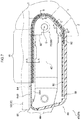
- FIG. 7 is a cross-section illustrating an ottoman section of the vehicle seat in a state sectioned along line 7 - 7 in FIG. 3 ;
- FIG. 8 is a cross-section illustrating an ottoman section of the vehicle seat in a state sectioned along line 8 - 8 in FIG. 4 ;
- FIG. 9 is an enlarged partial cross-section illustrating the ottoman section illustrated in FIG. 7 ;
- FIG. 10A is a cross-section illustrating a cover member of an ottoman section in a state sectioned along line A-A in FIG. 7 ;
- FIG. 10B is a cross-section illustrating a cover member of an ottoman section in a state sectioned along line B-B in FIG. 7 ;
- FIG. 10C is a cross-section illustrating a cover member of an ottoman section in a state sectioned along line C-C in FIG. 7 ;
- FIG. 10D is a cross-section illustrating a cover member of an ottoman section in a state sectioned along line D-D in FIG. 7 ;
- FIG. 11 is an enlarged partial cross-section corresponding to FIG. 9 to explain a comparative example.
- the arrow FR indicates a seat front side
- the arrow UP indicates a seat upper side
- the arrow LH indicates a seat left hand side (one side in a seat width direction) of the vehicle seat 10 , as appropriate.
- the seat front side, seat upper side, and seat left hand side of the vehicle seat 10 correspond to a vehicle front side, a vehicle upper side, and a vehicle left hand side of a vehicle (automobile) to which the vehicle seat 10 is installed.
- FIG. 1 is a perspective view illustrating a state in which the seat orientation of the vehicle seat 10 has been set to a forward-facing orientation (an orientation aligned with the direction of vehicle travel).
- FIG. 2 is a perspective view illustrating framework members of the vehicle seat 10 .
- the vehicle seat 10 includes a base section 12 configuring a lower section of the vehicle seat 10 , and a pair of seat sections 14 tiltably supported by the base section 12 .
- Each of the pair of seat sections 14 is configured including a lower cushion section 16 , a middle cushion section 18 , and an upper cushion section 20 disposed in series.
- Framework members configuring these sections are coupled together by hinge mechanisms 60 located inside the respective seat sections 14 .
- the base section 12 is, for example, formed by pressing sheet metal, and is fixed to a vehicle floor using non-illustrated fastenings.
- the pair of seat sections 14 are installed above the base section 12 .
- the base section 12 and the seat sections 14 are coupled together through first hinges 62 included in the hinge mechanisms 60 , described later.
- Each of the pair of seat sections 14 is supported by the base section 12 so as to be capable of tilting about an axis running in the seat width direction.
- the pair of seat sections 14 are disposed opposing each other as viewed along the seat width direction, and are structurally symmetrical about the base section 12 .
- the seat section disposed toward the seat front-rear direction front side of the vehicle seat 10 is labelled a seat section 14 A
- the seat section disposed toward the seat front-rear direction rear side of the vehicle seat 10 is labelled a seat section 14 B.
- the seat sections 14 A, 14 B are each configured by the lower cushion section 16 , the middle cushion section 18 , and the upper cushion section 20 , serially arranged in this sequence on progression from a base end of the seat section 14 toward a leading end of the seat section 14 so as to support the body of an occupant seated in the vehicle seat 10 .
- the lower cushion section 16 , the middle cushion section 18 , and the upper cushion section 20 are respectively coupled together by a second hinge 64 and a third hinge 68 included in the hinge mechanisms 60 .
- each of the lower cushion sections 16 includes a lower frame 22 configuring a framework member of the lower cushion section 16 .
- the lower frame 22 is, for example, formed by pressing sheet metal, and is formed in a substantially rectangular shape overall when viewed face-on.
- a seat back face side of the lower frame 22 has a case shape opening toward a seat front face side, and is covered by an integrally formed resin lower casing 24 .
- a seat front face side of the lower frame 22 is covered by a lower pad 26 .
- the lower pad 26 is configured from a foamed material such as urethane, and is covered by a surface covering 28 .
- the first hinge 62 is configured by a known powered round recliner mechanism, and includes a non-illustrated electric motor serving as a drive source and a non-illustrated shaft configuring an output shaft of the electric motor.
- the shaft is disposed with its axial direction in the seat width direction, and connection portions 13 (see FIG. 2 ) projecting upright from an upper face of the base section 12 and one end of the lower frame 22 are connected to both axial direction end portions of the shaft.
- the lower cushion section 16 is thus capable of tilting relative to the base section 12 when the electric motor rotates forward or in reverse.
- the lower frame 22 is coupled to the middle cushion section 18 through the second hinge 64 at the other end of the lower frame 22 in the direction orthogonal to the seat width direction so as to be capable of pivoting.
- the middle cushion section 18 includes a middle frame 30 configuring a framework member of the middle cushion section 18 .
- the middle frame 30 is, for example, formed by pressing sheet metal, and is formed in a substantially rectangular shape overall when viewed face-on.
- a seat back face side of the middle frame 30 has a case shape opening toward a seat front face side, and is covered by an integrally formed resin middle casing 32 .
- a seat front face side of the middle frame 30 is covered by a middle pad 34 .
- the middle pad 34 is configured from a foamed material such as urethane, and is covered by the surface covering 28 .
- the second hinge 64 is provided on both seat width direction sides of the seat section 14 , and includes a pair of links 66 having a length direction running in a direction substantially orthogonal to the seat width direction. Both length direction end portions of each of the pair of links 66 are disposed at the inner sides of the lower casing 24 and the middle casing 32 respectively. Moreover, each of these end portions are coupled to one end of the lower frame 22 or one end of the middle frame 30 through a powered round recliner mechanism similar to that of the first hinge 62 described above.
- the second hinge 64 includes a pair of shafts joined to the lower frame 22 and the middle frame 30 respectively.
- the two axial direction end portions of each of the pair of shafts configure a double hinge mechanism, and are coupled together through the pair of links 66 .
- the middle cushion section 18 is thus capable of pivoting relative to the lower cushion section 16 about an axis running in the seat width direction when electric motors fixed to the respective shafts rotate forward or in reverse.
- the other end of the middle frame 30 in the direction orthogonal to the seat width direction is coupled to the upper cushion section 20 through the third hinge 68 so as to be capable of pivoting.
- the upper cushion section 20 is configured including an ottoman section 40 disposed at a leading end portion of the corresponding seat section 14 , and a headrest section 50 supported by the ottoman section 40 so as to be capable of pivoting.
- the ottoman section 40 includes an ottoman frame 42 serving as a framework member (see FIG. 2 and FIG. 5 ).
- the headrest section 50 corresponds to a rotatable body of the present disclosure.
- the ottoman frame 42 is, for example, formed by pressing sheet metal, and is formed in a substantially trapezoid plate shape.
- a base end portion side of the ottoman frame 42 (corresponding to the lower base of the trapezoid shape) is provided with a pair of coupling brackets 44 extending toward the middle cushion section 18 .
- Each of the coupling brackets 44 is formed in an elongated shape with its plate thickness direction aligned with the seat width direction, and a leading end portion of each of the coupling brackets 44 is coupled to the other end of the middle frame 30 through the third hinge 68 .
- the third hinge 68 is configured by a known powered round recliner mechanism, and is coupled to the other end of the middle frame 30 and to leading end portions of the pair of coupling brackets 44 through a shaft (not illustrated in the drawings) with its axial direction along the seat width direction.
- the ottoman section 40 pivots relative to the middle cushion section 18 about an axis running in the seat width direction when an electric motor (not illustrated in the drawings) serving as a drive source rotates forward or in reverse.
- a leading end side of the ottoman frame 42 (corresponding to the upper base of the trapezoid shape) is provided with a coupling section 70 included in the hinge mechanisms 60 between a pair of fixing plates 46 that project upright toward the leading end side of the ottoman frame 42 .
- a front face of the ottoman frame 42 is covered by a cover member 48 configuring a seat opening concealment structure according to the present exemplary embodiment.
- the headrest section 50 includes a headrest frame 52 , serving as a framework member.
- the headrest frame 52 is formed in a substantially trapezoid plate shape.
- a support plate 54 projects upright from a leading end side of the headrest frame 52 (corresponding to the upper base of the trapezoid shape), and the headrest frame 52 is fixed to the coupling section 70 through the support plate 54 .
- a seat back face side of the headrest frame 52 is covered by headrest casing 56 .
- the headrest casing 56 is formed in a substantially trapezoid shape, and has a shallow-bottomed case shape opening toward the seat front face side.
- the seat front face side of the headrest frame 52 is covered by a headrest pad 58 .
- the headrest pad 58 is configured from a foamed material such as urethane, and is covered by the surface covering 28 .
- the coupling section 70 couples the ottoman section 40 and the headrest section 50 of the upper cushion section 20 together so as to be capable of pivoting.
- the coupling section 70 includes an electric motor 72 serving as a drive source, a pinion gear 74 configuring an output shaft of the electric motor 72 , a sector gear 76 that meshes with the pinion gear 74 , and a gear bracket 78 that fixes and supports the sector gear 76 .
- the electric motor 72 is fastened and fixed to a seat width direction inner side of one of the fixing plates 46 that projects upright from the leading end portion of the ottoman frame 42 using motor bolts and nuts (neither of which are allocated a reference numeral).
- the pinion gear 74 configuring the output shaft of the electric motor 72 is disposed with its axial direction along the seat width direction. Teeth formed to a leading end of the pinion gear 74 mesh with teeth of the sector gear 76 .
- the sector gear 76 is disposed with its axial direction along the seat width direction, and is fixed and supported by the gear bracket 78 .
- the gear bracket 78 is, for example, formed by pressing sheet metal, and is fastened and fixed to the support plate 54 of the headrest frame 52 using plural non-illustrated bolts and nuts such that the leading end portion of the gear bracket 78 extends so as to link together the ottoman frame 42 and the headrest frame 52 .
- Base end portions of the sector gear 76 and the gear bracket 78 are supported so as to be capable of pivoting by the pair of fixing plates 46 of the ottoman frame 42 using a pair of pins (not allocated reference numerals).
- a tube shaped housing 80 extending from the ottoman frame 42 toward the headrest frame 52 covers the periphery of the sector gear 76 and the gear bracket 78 .
- the housing 80 is inserted through an opening 82 formed in the cover member 48 that covers the front face of the ottoman frame 42 , and one axial direction end of the housing 80 is fixed to a rotation shaft Q of the coupling section 70 (the center of the sector gear 76 ).
- the other axial direction end portion of the housing 80 is fixed to a bottom face of the headrest casing 56 .
- the coupling section 70 Due to the configuration described above, in the coupling section 70 , actuating the electric motor 72 causes the sector gear 76 to be rotated forward or in reverse through the pinion gear 74 configuring the output shaft. The rotation motion of the sector gear 76 is received by the gear bracket 78 , which pivots relative to the ottoman frame 42 . In this manner, the headrest section 50 is supported by the ottoman section 40 through the coupling section 70 so as to be capable of pivoting.
- the headrest section 50 is pivoted to change the position of the headrest section 50 between a “headrest position” and an “ottoman position”.
- the headrest position refers to a state in which the ottoman section 40 and the headrest section 50 are folded over and superimposed on one another ( FIG. 3 ). In this state, the headrest pad 58 of the headrest section 50 is disposed at the seat front face side of the upper cushion section 20 . Accordingly, as illustrated in FIG.
- the headrest section 50 in a seat mode in which the seat section 14 B is standing upright toward the seat upper side and the upper body of a seated occupant is supported by the seat section 14 B, the headrest section 50 is set to the headrest position in which the headrest pad 58 is capable of supporting the head of the seated occupant from the seat rear side.
- the ottoman position refers to a state in which the headrest section 50 has been pivoted in a direction away from the ottoman section 40 ( FIG. 4 ).
- the ottoman section 40 is disposed at the seat front face side of the upper cushion section 20 .
- the headrest section 50 is set in the ottoman position in which the ottoman section 40 is capable of supporting the feet of the seated occupant from the seat lower side.
- the vehicle seat 10 includes an electronic control unit (ECU) serving as a control device to control the hinge mechanisms 60 .
- the ECU is configured by a microcomputer in which a CPU, ROM, RAM, and an input/output interface (I/O) are each connected to a bus.
- the I/O of the ECU is electrically connected to the plural electric motors included in the first hinge 62 , the second hinge 64 , the third hinge 68 , and the coupling section 70 configuring the hinge mechanisms 60 .
- the I/O of the ECU is also electrically connected to a non-illustrated operation section provided close to the vehicle seat 10 .
- Switches are provided to the operation section in order to select between plural seat modes, enabling selection of a desired seat mode from out of plural (various) modes stored in advance in the ROM of the ECU.
- the ECU controls driving of the electric motors according to the mode selected using the mode selection switches.
- the vehicle seat 10 Under the control of the ECU, the vehicle seat 10 can be set to a forward-facing seat orientation in which the seat section 14 B stands upright as illustrated in FIG. 1 . On the other hand, under the control of the ECU the vehicle seat 10 can also be set to a rearward-facing seat orientation in which the seat section 14 A stands upright and the seat section 14 B is disposed extending toward the seat rear side. Moreover, the ECU is also capable of changing the layout of the seat sections 14 A, 14 B so as to follow the posture of the seated occupant by controlling the tilt of the lower cushion sections 16 , the middle cushion sections 18 , and the upper cushion sections 20 as desired.
- the seat opening concealment structure is applied to the opening 82 formed in the cover member 48 of the ottoman section 40 described above.
- the seat opening concealment structure is principally configured by the cover member 48 and a single concealing sheet 92 .
- the cover member 48 is, for example, made from resin, and is formed as a flattened hollow case with an outer wall 84 configuring a design face.
- the cover member 48 is divided into top and bottom, and is configured by a mutually joined upper cover 48 A and lower cover 48 B.
- the upper cover 48 A and the lower cover 48 B are, for example, joined together by clips.
- the upper cover 48 A is formed as a substantially trapezoid shaped lid configuring an upper portion (seat front face side) of the cover member 48 .
- the feet of the seated occupant can be placed on the upper cover 48 A that is disposed on the seat front face side of the upper cushion section 20 when the position of the headrest section 50 has been set to the ottoman position.
- the lower cover 48 B is configured as a substantially trapezoid shaped case opening toward the upper cover 48 A, and configures a lower portion (seat back face side) of the cover member 48 .
- a base end portion side of the lower cover 48 B (corresponding to the lower base of the trapezoid shape) is formed with a pair of elongated holes 86 through which the pair of coupling brackets 44 provided to the ottoman frame 42 are inserted.
- FIG. 7 and FIG. 8 are cross-sections illustrating the outer wall 84 of the cover member 48 .
- a leading end portion side of the cover member 48 (corresponding to the upper base of the trapezoid shape) is formed with a flat face portion W, a curved face portion X, an inclined portion Y, and a bent portion Z, provided continuously to one another.
- the flat face portion W is formed with a linear cross-section profile, and forms a flat face on the seat front face side of the cover member 48 .
- the curved face portion X is formed with a circular arc shaped cross-section profile, and forms a curved face corresponding to a rotation trajectory of the headrest section 50 .
- the curved face portion X is also formed with the elongated opening 82 following a peripheral direction of the curved face portion X.
- the coupling section 70 joined to the headrest section 50 is inserted through the opening 82 .
- the inclined portion Y is formed extending at an incline from an end portion of the curved face portion X toward the seat back face side. An end portion of the inclined portion Y is bent toward a direction substantially parallel with the flat face portion W, thus forming the bent portion Z.
- a pair of upright walls 88 and a pair of inner walls 90 are provided inside the cover member 48 .
- the pair of upright walls 88 are disposed on both short direction sides of the opening 82 , and project upright from the corresponding outer wall 84 toward the inside of the cover member 48 , extending so as to follow the extension direction of the opening 82 .
- the pair of inner walls 90 are bent from leading ends of the pair of upright walls 88 , and are disposed jutting out toward the opening 82 so as to oppose the outer wall 84 .
- the inner walls 90 extend so as to oppose each of the flat face portion W, the curved face portion X, the inclined portion Y, and the bent portion Z of the outer wall 84 .
- the concealing sheet 92 is disposed between the pair of upright walls 88 such that the two seat width direction end portions of the concealing sheet 92 are supported by the pair of upright walls 88 . In this state, the two end portions of the concealing sheet 92 are inserted into gaps G between the outer wall 84 and the inner walls 90 .
- the concealing sheet 92 is formed in an elongated rectangular shape that is longer than the extension direction length of the opening 82 .
- a seat width direction dimension of the concealing sheet 92 is set larger than the width of the opening 82 .
- the concealing sheet 92 is attached to the cover member 48 by inserting the two length direction ends of the concealing sheet 92 in the direction of the arrows in FIG. 6 , namely into the upper cover 48 A and the lower cover 48 B configuring the top and bottom of the divided cover member 48 .
- an attachment hole 94 having substantially the same dimensions as the outer profile of the housing 80 of the coupling section 70 is formed through a length direction intermediate portion of the concealing sheet 92 .
- the housing 80 of the coupling section 70 is inserted through the attachment hole 94 and fixed to the coupling section 70 .
- the concealing sheet 92 covers the opening 82 while moving (sliding) along an inner face 84 A of the outer wall 84 (see the directions indicated by the arrows in FIG. 8 ).
- FIG. 9 is an enlarged cross-section illustrating the flat face portion W and the curved face portion X of the outer wall 84 of the cover member 48 .
- the flat face portion W is formed with a substantially uniform plate thickness
- the curved face portion X has a gradually changing plate thickness that is thicker than that of the flat face portion W.
- the radius of curvature of the inner face 84 A that contacts the concealing sheet 92 is formed larger than the radius of curvature of an outer face 84 B configuring a design face of the cover member 48 .
- a curve of the inner face 84 A that the concealing sheet 92 contacts is gentler than a curve of the outer face 84 B, thereby reducing interference between the concealing sheet 92 and the outer wall 84 .
- an angle ⁇ (0° ⁇ 90°) formed between a straight line T 1 in the direction of the component Fs and a straight line T 2 in the direction of the external force F is denoted ⁇ 1.
- the size of the external force F in Equations (1) and (2) is substantially equivalent to the drive force of the electric motor 72 of the coupling section 70 , and is accordingly a constant value. Therefore the following relationship is established.
- Fr 1 F ⁇ sin ⁇ 1 ⁇
- Fr 2 F ⁇ sin ⁇ 2 (3)
- Equation (3) setting the radius of curvature of the inner face 84 A that contacts the concealing sheet 92 larger than the radius of curvature of the outer face 84 B reduces interference between the concealing sheet 92 and the outer wall 84 .
- the radius of curvature of the inner face 84 A is likewise set larger than the radius of curvature of the outer face 84 B, for similar reasons.
- the gaps G formed between the outer wall 84 and the inner walls 90 .
- the gaps G are formed in the relationship expressed by Equation (4) above by setting the inner walls 90 with a thinner plate thickness at locations opposing the curved face portion X and the bent portion Z than at locations opposing the flat face portion W and the inclined portion Y.
- the combined plate thickness is thus regulated by reducing the plate thickness of the inner walls 90 at the curved face portion X where the outer wall 84 is thicker.
- the seat sections 14 A, 14 B can be set to desired angles under the control of the non-illustrated ECU. Accordingly, when a seat section 14 is supporting the lower body of the seated occupant as in the case of the seat section 14 A illustrated in FIG. 1 , the seated occupant can place their feet on the cover member 48 of the ottoman section 40 . On the other hand, when a seat section 14 is supporting the upper body of the seated occupant as in the case of the seat section 14 B illustrated in FIG. 1 , the headrest section 50 is able to support the head of the seated occupant.
- the coupling section 70 coupling together the ottoman section 40 and the headrest section 50 is inserted through the opening 82 formed following the peripheral direction of the curved face portion X of the outer wall 84 of the cover member 48 .
- the elongated concealing sheet 92 is disposed at the inner side of the outer wall 84 so as to slide along the inner face 84 A following the pivoting of the coupling section 70 . Accordingly, the concealing sheet 92 is able to keep the opening 82 covered at all times, and foreign objects, for example foreign objects stuck to the feet of the seated occupant, can be suppressed from entering the interior of the seat section 14 (ottoman section 40 ).
- the radius of curvature of the inner face 84 A is larger than the radius of curvature of the outer face 84 B at the curved face portion X of the outer wall 84 .
- the inner face 84 A that contacts the concealing sheet 92 is formed with a gentler curve than the curve of the outer face 84 B. This reduces interference between the inner face 84 A and the concealing sheet 92 , enabling the concealing sheet 92 to slide smoothly.
- this does not incur constraints regarding the outer face 84 B, it is possible to achieve both functionality and pleasing design characteristics.
- the two seat width direction end portions of the concealing sheet 92 are covered by the inner walls 90 . Accordingly, if the concealing sheet 92 wobbles due to interference with the outer wall 84 , the two end portions of the concealing sheet 92 abut and are supported by the inner walls 90 . This enables movement of the concealing sheet 92 to be stabilized.
- the concealing sheet 92 is able to slide even more smoothly as a result.
- the plate thickness of the outer wall 84 is thicker at the curved face portion X than at the flat face portion W, while the plate thickness of the inner walls 90 is set thinner at locations opposing the curved face portion X than at locations opposing the flat face portion W by a commensurate amount. This suppresses an increase in the combined plate thicknesses of the cover member 48 at the curved face portion X, thereby enabling optimal plate thickness to be achieved throughout the overall cover member 48 .
- the seat opening concealment structure is applied to the opening 82 formed in the ottoman section 40 in the above exemplary embodiment, the present disclosure is not limited thereto, and the seat opening concealment structure may be applied to an opening formed at another location on the seat sections 14 .
- application may be made to an opening formed in the lower casing 24 of the lower cushion section 16 or in the middle casing 32 of the middle cushion section 18 .
- the concealing sheet 92 is supported by the outer wall 84 , the upright walls 88 , and the inner walls 90 in the above exemplary embodiment, the present disclosure is not limited thereto, and the concealing sheet may be supported by the outer walls and the upright walls alone.
- the plate thickness of the inner walls 90 is set thinner at the locations opposing the curved face portion X than the plate thickness of the inner walls 90 at the locations opposing the flat face portion W in the above exemplary embodiment, the present disclosure is not limited thereto, and the inner walls 90 may be formed with uniform plate thickness.
Landscapes
- Engineering & Computer Science (AREA)
- Transportation (AREA)
- Mechanical Engineering (AREA)
- Aviation & Aerospace Engineering (AREA)
- Seats For Vehicles (AREA)
- Passenger Equipment (AREA)
- Chairs For Special Purposes, Such As Reclining Chairs (AREA)
Abstract
Description
Fr1=F×sin θ1 (1)
Fr2=F×sin θ2(θ2>θ1) (2)
Fr1=F×sin θ1<Fr2=F×sin θ2 (3)
G1=G3<G2=G4 (4)
Claims (6)
Applications Claiming Priority (3)
| Application Number | Priority Date | Filing Date | Title |
|---|---|---|---|
| JP2019-090114 | 2019-05-10 | ||
| JP2019090114A JP7206547B2 (en) | 2019-05-10 | 2019-05-10 | Blindfold structure for the seat opening. |
| JPJP2019-090114 | 2019-05-10 |
Publications (2)
| Publication Number | Publication Date |
|---|---|
| US20200353845A1 US20200353845A1 (en) | 2020-11-12 |
| US11173810B2 true US11173810B2 (en) | 2021-11-16 |
Family
ID=73047080
Family Applications (1)
| Application Number | Title | Priority Date | Filing Date |
|---|---|---|---|
| US16/861,278 Expired - Fee Related US11173810B2 (en) | 2019-05-10 | 2020-04-29 | Seat opening concealment structure |
Country Status (3)
| Country | Link |
|---|---|
| US (1) | US11173810B2 (en) |
| JP (1) | JP7206547B2 (en) |
| CN (1) | CN111907388A (en) |
Cited By (1)
| Publication number | Priority date | Publication date | Assignee | Title |
|---|---|---|---|---|
| US20240227629A1 (en) * | 2021-10-14 | 2024-07-11 | Ningbo Geely Automobile Research & Development Co., Ltd. | Vehicle seat and a method for operating a vehicle seat |
Families Citing this family (3)
| Publication number | Priority date | Publication date | Assignee | Title |
|---|---|---|---|---|
| JP7137605B2 (en) | 2020-11-06 | 2022-09-14 | 日立建機株式会社 | Vehicle management system |
| JP7476821B2 (en) * | 2021-02-25 | 2024-05-01 | トヨタ自動車株式会社 | Vehicle occupant restraint device |
| KR20230020154A (en) * | 2021-08-03 | 2023-02-10 | 현대자동차주식회사 | Seat for vehicle |
Citations (5)
| Publication number | Priority date | Publication date | Assignee | Title |
|---|---|---|---|---|
| US4693515A (en) * | 1986-10-27 | 1987-09-15 | Itt Corporation | Headrest for an automotive vehicle seat |
| US20140339875A1 (en) * | 2013-05-15 | 2014-11-20 | Nhk Spring Co., Ltd. | Headrest structure and headrest device |
| US20170291516A1 (en) * | 2016-04-11 | 2017-10-12 | Dorel Juvenile Group, Inc. | Headrest |
| US20190359087A1 (en) * | 2016-09-08 | 2019-11-28 | Shanghai Yanfeng Jinqiao Automotive Trim Systems Co. Ltd. | Seat assembly and configuration for a vehicle interior |
| US20200196765A1 (en) * | 2016-12-27 | 2020-06-25 | Stelia Aerospace | Armchair comprising an adjustable headrest |
Family Cites Families (2)
| Publication number | Priority date | Publication date | Assignee | Title |
|---|---|---|---|---|
| JPH08119013A (en) * | 1994-10-25 | 1996-05-14 | Araco Corp | Front seat for automobile |
| JP6351165B2 (en) | 2014-06-18 | 2018-07-04 | 株式会社タチエス | Headrest |
-
2019
- 2019-05-10 JP JP2019090114A patent/JP7206547B2/en active Active
-
2020
- 2020-04-24 CN CN202010335199.9A patent/CN111907388A/en active Pending
- 2020-04-29 US US16/861,278 patent/US11173810B2/en not_active Expired - Fee Related
Patent Citations (6)
| Publication number | Priority date | Publication date | Assignee | Title |
|---|---|---|---|---|
| US4693515A (en) * | 1986-10-27 | 1987-09-15 | Itt Corporation | Headrest for an automotive vehicle seat |
| US20140339875A1 (en) * | 2013-05-15 | 2014-11-20 | Nhk Spring Co., Ltd. | Headrest structure and headrest device |
| JP2014223842A (en) | 2013-05-15 | 2014-12-04 | 日本発條株式会社 | Headrest structure and headrest device |
| US20170291516A1 (en) * | 2016-04-11 | 2017-10-12 | Dorel Juvenile Group, Inc. | Headrest |
| US20190359087A1 (en) * | 2016-09-08 | 2019-11-28 | Shanghai Yanfeng Jinqiao Automotive Trim Systems Co. Ltd. | Seat assembly and configuration for a vehicle interior |
| US20200196765A1 (en) * | 2016-12-27 | 2020-06-25 | Stelia Aerospace | Armchair comprising an adjustable headrest |
Cited By (1)
| Publication number | Priority date | Publication date | Assignee | Title |
|---|---|---|---|---|
| US20240227629A1 (en) * | 2021-10-14 | 2024-07-11 | Ningbo Geely Automobile Research & Development Co., Ltd. | Vehicle seat and a method for operating a vehicle seat |
Also Published As
| Publication number | Publication date |
|---|---|
| JP2020185835A (en) | 2020-11-19 |
| JP7206547B2 (en) | 2023-01-18 |
| CN111907388A (en) | 2020-11-10 |
| US20200353845A1 (en) | 2020-11-12 |
Similar Documents
| Publication | Publication Date | Title |
|---|---|---|
| US11173810B2 (en) | Seat opening concealment structure | |
| US7614693B2 (en) | Seating area adjuster | |
| US20090236891A1 (en) | Motion converting drive mechanism and vehicle seat apparatus including the same | |
| CN108349414A (en) | Seat | |
| JP7775772B2 (en) | Vehicle seat frame structure | |
| JP7718232B2 (en) | Door opening and closing device | |
| JP5047522B2 (en) | Retractable roof and vehicle equipped with the same | |
| US7168816B2 (en) | Vehicle door mirror device | |
| JP5866159B2 (en) | Vehicle seat | |
| US5486036A (en) | Seat-height adjusting device | |
| JP7776643B2 (en) | seat frame | |
| JP4790465B2 (en) | Retractable roof and vehicle equipped with the same | |
| JP7157358B2 (en) | seat device | |
| KR101470223B1 (en) | Apparatus for seat side bolster of vehicle | |
| US11745626B2 (en) | Dual gear type recliner device for a vehicle seat | |
| JP3646909B2 (en) | Automotive window regulator | |
| JP2021195033A (en) | Steering column device | |
| KR102360583B1 (en) | Concentric type continuous recliner | |
| JP2005313869A (en) | Mounting structure of double folding seat for vehicles | |
| KR102824781B1 (en) | Extensible apparatus for side portion of seat cushion | |
| JP5871511B2 (en) | Vehicle seat and manufacturing method thereof | |
| JPH07315084A (en) | Seat cushion length adjusting mechanism | |
| JP3717563B2 (en) | Reclining structure for vehicle power seat | |
| JP2007261407A (en) | Retractable roof, and vehicle provided with the same | |
| KR100551769B1 (en) | Seat track interlocking seat tilt device of car |
Legal Events
| Date | Code | Title | Description |
|---|---|---|---|
| AS | Assignment |
Owner name: NHK SPRING CO., LTD, JAPAN Free format text: ASSIGNMENT OF ASSIGNORS INTEREST;ASSIGNORS:MATSUZAWA, TSUYOSHI;KATSUBE, KENICHI;TANAKA, DAISUKE;REEL/FRAME:052525/0590 Effective date: 20200415 |
|
| FEPP | Fee payment procedure |
Free format text: ENTITY STATUS SET TO UNDISCOUNTED (ORIGINAL EVENT CODE: BIG.); ENTITY STATUS OF PATENT OWNER: LARGE ENTITY |
|
| STPP | Information on status: patent application and granting procedure in general |
Free format text: APPLICATION DISPATCHED FROM PREEXAM, NOT YET DOCKETED |
|
| STPP | Information on status: patent application and granting procedure in general |
Free format text: DOCKETED NEW CASE - READY FOR EXAMINATION |
|
| STPP | Information on status: patent application and granting procedure in general |
Free format text: NON FINAL ACTION MAILED |
|
| STPP | Information on status: patent application and granting procedure in general |
Free format text: RESPONSE TO NON-FINAL OFFICE ACTION ENTERED AND FORWARDED TO EXAMINER |
|
| STPP | Information on status: patent application and granting procedure in general |
Free format text: NOTICE OF ALLOWANCE MAILED -- APPLICATION RECEIVED IN OFFICE OF PUBLICATIONS |
|
| STPP | Information on status: patent application and granting procedure in general |
Free format text: PUBLICATIONS -- ISSUE FEE PAYMENT VERIFIED |
|
| STCF | Information on status: patent grant |
Free format text: PATENTED CASE |
|
| FEPP | Fee payment procedure |
Free format text: MAINTENANCE FEE REMINDER MAILED (ORIGINAL EVENT CODE: REM.); ENTITY STATUS OF PATENT OWNER: LARGE ENTITY |
|
| LAPS | Lapse for failure to pay maintenance fees |
Free format text: PATENT EXPIRED FOR FAILURE TO PAY MAINTENANCE FEES (ORIGINAL EVENT CODE: EXP.); ENTITY STATUS OF PATENT OWNER: LARGE ENTITY |
|
| STCH | Information on status: patent discontinuation |
Free format text: PATENT EXPIRED DUE TO NONPAYMENT OF MAINTENANCE FEES UNDER 37 CFR 1.362 |
|
| FP | Lapsed due to failure to pay maintenance fee |
Effective date: 20251116 |