US11169211B2 - Systems, methods and apparatuses for frequency tracking - Google Patents
Systems, methods and apparatuses for frequency tracking Download PDFInfo
- Publication number
- US11169211B2 US11169211B2 US16/601,261 US201916601261A US11169211B2 US 11169211 B2 US11169211 B2 US 11169211B2 US 201916601261 A US201916601261 A US 201916601261A US 11169211 B2 US11169211 B2 US 11169211B2
- Authority
- US
- United States
- Prior art keywords
- frequency
- shaft
- stator voltage
- fault condition
- measured
- Prior art date
- Legal status (The legal status is an assumption and is not a legal conclusion. Google has not performed a legal analysis and makes no representation as to the accuracy of the status listed.)
- Active, expires
Links
- 238000000034 method Methods 0.000 title claims description 42
- 239000000203 mixture Substances 0.000 claims abstract description 9
- 238000005259 measurement Methods 0.000 claims description 91
- 238000012545 processing Methods 0.000 claims description 26
- 230000001052 transient effect Effects 0.000 claims description 25
- 238000002156 mixing Methods 0.000 claims description 7
- 230000008569 process Effects 0.000 claims description 7
- 238000003860 storage Methods 0.000 description 18
- 230000006870 function Effects 0.000 description 10
- 238000004891 communication Methods 0.000 description 9
- 238000001914 filtration Methods 0.000 description 8
- 230000004044 response Effects 0.000 description 8
- 230000008901 benefit Effects 0.000 description 7
- 230000008859 change Effects 0.000 description 6
- 238000004590 computer program Methods 0.000 description 6
- 230000001360 synchronised effect Effects 0.000 description 6
- 230000001133 acceleration Effects 0.000 description 4
- 230000000295 complement effect Effects 0.000 description 4
- 238000012986 modification Methods 0.000 description 4
- 230000004048 modification Effects 0.000 description 4
- 238000011326 mechanical measurement Methods 0.000 description 3
- 239000008186 active pharmaceutical agent Substances 0.000 description 2
- 230000003993 interaction Effects 0.000 description 2
- 230000006855 networking Effects 0.000 description 2
- 230000003287 optical effect Effects 0.000 description 2
- 102000003712 Complement factor B Human genes 0.000 description 1
- 108090000056 Complement factor B Proteins 0.000 description 1
- 238000013459 approach Methods 0.000 description 1
- 238000013329 compounding Methods 0.000 description 1
- 230000000694 effects Effects 0.000 description 1
- 230000003090 exacerbative effect Effects 0.000 description 1
- 238000009434 installation Methods 0.000 description 1
- 238000004519 manufacturing process Methods 0.000 description 1
- 239000000463 material Substances 0.000 description 1
- 230000005055 memory storage Effects 0.000 description 1
- 229920000729 poly(L-lysine) polymer Polymers 0.000 description 1
- 230000001681 protective effect Effects 0.000 description 1
Images


Classifications
-
- G—PHYSICS
- G01—MEASURING; TESTING
- G01P—MEASURING LINEAR OR ANGULAR SPEED, ACCELERATION, DECELERATION, OR SHOCK; INDICATING PRESENCE, ABSENCE, OR DIRECTION, OF MOVEMENT
- G01P3/00—Measuring linear or angular speed; Measuring differences of linear or angular speeds
- G01P3/42—Devices characterised by the use of electric or magnetic means
- G01P3/44—Devices characterised by the use of electric or magnetic means for measuring angular speed
- G01P3/48—Devices characterised by the use of electric or magnetic means for measuring angular speed by measuring frequency of generated current or voltage
- G01P3/481—Devices characterised by the use of electric or magnetic means for measuring angular speed by measuring frequency of generated current or voltage of pulse signals
- G01P3/487—Devices characterised by the use of electric or magnetic means for measuring angular speed by measuring frequency of generated current or voltage of pulse signals delivered by rotating magnets
-
- G—PHYSICS
- G01—MEASURING; TESTING
- G01R—MEASURING ELECTRIC VARIABLES; MEASURING MAGNETIC VARIABLES
- G01R31/00—Arrangements for testing electric properties; Arrangements for locating electric faults; Arrangements for electrical testing characterised by what is being tested not provided for elsewhere
- G01R31/34—Testing dynamo-electric machines
- G01R31/343—Testing dynamo-electric machines in operation
-
- G—PHYSICS
- G01—MEASURING; TESTING
- G01D—MEASURING NOT SPECIALLY ADAPTED FOR A SPECIFIC VARIABLE; ARRANGEMENTS FOR MEASURING TWO OR MORE VARIABLES NOT COVERED IN A SINGLE OTHER SUBCLASS; TARIFF METERING APPARATUS; MEASURING OR TESTING NOT OTHERWISE PROVIDED FOR
- G01D3/00—Indicating or recording apparatus with provision for the special purposes referred to in the subgroups
- G01D3/02—Indicating or recording apparatus with provision for the special purposes referred to in the subgroups with provision for altering or correcting the law of variation
-
- G—PHYSICS
- G01—MEASURING; TESTING
- G01P—MEASURING LINEAR OR ANGULAR SPEED, ACCELERATION, DECELERATION, OR SHOCK; INDICATING PRESENCE, ABSENCE, OR DIRECTION, OF MOVEMENT
- G01P3/00—Measuring linear or angular speed; Measuring differences of linear or angular speeds
- G01P3/42—Devices characterised by the use of electric or magnetic means
- G01P3/44—Devices characterised by the use of electric or magnetic means for measuring angular speed
- G01P3/48—Devices characterised by the use of electric or magnetic means for measuring angular speed by measuring frequency of generated current or voltage
- G01P3/4802—Devices characterised by the use of electric or magnetic means for measuring angular speed by measuring frequency of generated current or voltage by using electronic circuits in general
Definitions
- the present disclosure relates generally to the field of frequency tracking of synchronous machines.
- FIG. 1 illustrates a frequency tracking graph depicting measurement lag introduced by filtering and frequency locking techniques in accordance with one embodiment.
- FIG. 2 illustrates a frequency measurement device in accordance with one embodiment.
- FIG. 3 illustrates a frequency tracking system in accordance with one embodiment.
- FIG. 4 illustrates a frequency tracking system in accordance with one embodiment.
- FIG. 5 illustrates a flow chart of a method for tracking frequency in accordance with one embodiment.
- Modern microprocessor relays keep a running estimate of power system frequency. This estimate can be derived from an alternating current (AC) voltage waveform using several techniques.
- One technique includes a relay to measure the time between zero crossings or offset-zero crossings of the voltage waveform and then filtering the measurements. Frequency is estimated using the inverse of the time between crossings. Frequency is then tracked in relays with techniques such as phase locked loops (PLL) or observers designed to reject bad zero crossing data.
- PLL phase locked loops
- frequency is typically estimated with delay in the range of 20 to 200 milliseconds. Typically, shorter delay is associated with accuracy trade-offs under non-ideal conditions.
- Frequency measurement is an important function of relays. This is because frequency is used in the data processing of current and voltage measurements. For example, in some relays a cosine filter is driven by a frequency measurement algorithm. The outputs of the cosine filter are the 60 Hz components of the power system current and voltage, which are used for most metering and all protection functions.
- the systems, apparatuses, and methods described herein may provide reliable frequency measurements even during transient and fault conditions.
- the systems, apparatuses, and methods described herein may use both the voltage waveform and machine speed measurements.
- a frequency tracking device may receive shaft speed and position data from a first sensor and convert the shaft speed and position data to a rotational frequency of the shaft.
- the frequency tracking device may receive stator voltage frequency from a second sensor.
- the frequency tracking device may blend the stator voltage frequency and the rotational frequency based on a current operating state to determine a blended frequency measurement.
- the blended frequency measurement may provide a reliable frequency estimation with little lag.
- Coupled to refers to any form of interaction between two or more components, including mechanical, electrical, magnetic, and electromagnetic interaction. Two components may be connected to each other, even though they are not in direct contact with each other, and even though there may be intermediary devices between the two components.
- intelligent electronic device may refer to any microprocessor-based device that monitors, controls, automates, and/or protects monitored equipment within a system.
- Such devices may include, for example, remote terminal units, differential relays, distance relays, directional relays, feeder relays, overcurrent relays, voltage regulator controls, voltage relays, breaker failure relays, generator relays, motor relays, automation controllers, bay controllers, meters, recloser controls, communications processors, computing platforms, programmable logic controllers (PLCs), programmable automation controllers, input and output modules, motor drives, and the like.
- PLCs programmable logic controllers
- IEDs may be connected to a network, and communication on the network may be facilitated by networking devices including, but not limited to, multiplexers, routers, hubs, gateways, firewalls, and switches. Furthermore, networking and communication devices may be incorporated in an IED or be in communication with an IED.
- the term IED may be used interchangeably to describe an individual IED or a system comprising multiple IEDs.
- the frequency tracking devices and systems described herein may be a component of an IED or in communication with a separate IED.
- a software module or component may include any type of computer instruction or computer-executable code located within or on a computer-readable storage medium, such as a non-transitory computer-readable medium.
- a software module may, for instance, comprise one or more physical or logical blocks of computer instructions, which may be organized as a routine, program, object, component, data structure, etc., that perform one or more tasks or implement particular data types, algorithms, and/or methods.
- a particular software module may comprise disparate instructions stored in different locations of a computer-readable storage medium, which together implement the described functionality of the module.
- a module may comprise a single instruction or many instructions, and may be distributed over several different code segments, among different programs, and across several computer-readable storage media.
- Some embodiments may be practiced in a distributed computing environment where tasks are performed by a remote processing device linked through a communications network.
- software modules may be located in local and/or remote computer-readable storage media.
- data being tied or rendered together in a database record may be resident in the same computer-readable storage medium, or across several computer-readable storage media, and may be linked together in fields of a record in a database across a network.
- FIG. 1 illustrates a frequency tracking graph 100 in accordance with one embodiment.
- the frequency tracking graph 100 illustrates the effect of lagging measurements caused by filtering, PLLs, and other signal processing on frequency used in relays and other IEDs.
- the frequency tracking graph 100 shows how frequency tracking varies by manufacturer of relays, meters, and transducers.
- the frequency tracking graph 100 shows how lags in measurement amount to inaccuracies.
- the frequency tracking graph 100 includes an actual frequency 102 that is measured by a transducer, a first relay, and a second relay.
- the transducer produces a transducer estimated frequency 108 that fails to track closely the frequency change. The poor tracking of the transducer may result in misoperation.
- the second relay produces a relay B estimated frequency 106 .
- the relay B estimated frequency 106 may have a smaller lag in frequency measurement than the transducer estimated frequency 108 ; however, the relay B estimated frequency 106 still includes frequency measurement lag sufficient to fail to capture the significant drop in frequency of the actual frequency 102 .
- the frequency measurement lag may be due to filtering and hold-over techniques traditionally used in relays and transducers.
- the first relay may produce a relay A estimated frequency 104 that more closely tracks the actual frequency 102 than the relay B estimated frequency 106 and the transducer estimated frequency 108 .
- the relay A estimated frequency 104 illustrates an example output of embodiments of systems and methods to improve frequency tracking described herein.
- the first relay may have access to both the electrical measurements and the mechanical measurements of the machine.
- FIG. 2 illustrates a frequency measurement device 200 in accordance with one embodiment.
- the frequency measurement device 200 may capture a mechanical frequency 214 using engine measurements (e.g., machine speed and mechanical power) and capture an electrical frequency 208 using measurements of an electrical signal.
- engine measurements e.g., machine speed and mechanical power
- the frequency measurement device 200 may send both the mechanical frequency 214 and the electrical frequency 208 to a frequency tracking system to provide the frequency tracking system with both the electrical measurements and the mechanical measurements of a machine.
- the frequency tracking system may use engine measurements to augment stator voltage frequency measurements.
- the frequency measurement device 200 or portions of the frequency measurement device 200 are components of the frequency tracking system.
- the frequency measurement device 200 is separate from the frequency tracking system.
- a mechanical sensor 202 may take engine measurements which may include direct speed measurements and machine power measurements.
- the machine power measurements may indicate the operating power of a machine such as a generator or engine. In some embodiments, the machine may self-report the machine power measurements.
- the engine measurements may be taken from any synchronous machine, including motors and synchronous condensers. Engine measurements may be taken directly from a rotating machine or via a magnetic interface on power systems such as flywheels, diesel rotary uninterruptible power supply devices (DRUPS), wind turbines, etc.
- the mechanical sensor 202 may be an analog engine position sensor, a synchro, a resolver, an encoder, or other rotational position measuring device attached to an engine, a generator, or a motor.
- the mechanical sensor 202 may be a tooth wheel magnetic sensor. Measurements of machine speed on synchronous equipment such as generators or motors can make use of measurement devices such as tooth wheels and magnetic pickups to monitor shaft speed.
- the pulse information from magnetic sensors will typically be in the form of a count of the number of pulses counted within a processing interval or the duration between pulse arrival times. These values could be read directly by the physical data processor 210 , or interpreted by an intermediate device which then provides a digital or analog signal to the controller.
- the mechanical sensor 202 may perform well at tracking the engine speed during transients. Because the engine speed measurement is mechanical, the measurement does not rely on zero crossings of the output voltage. Thus, when a fault occurs, the mechanical sensor 202 will still be able to track the engine speed.
- the engine speed measured by the mechanical sensor 202 may be processed by a physical data processor 210 to determine a speed of a machine in rotations per minute (RPM).
- the physical data processor 210 may receive pulses from a tooth wheel magnetic sensor and measure the pulses to determine RPM of the machine.
- the physical data processor 210 may send the RPM measurement to a converter 212 .
- the tooth-wheel pulse data can be converted to a shaft speed via a variety of methods.
- One embodiment may use a Kalman Filter to estimate the shaft speed.
- Another embodiment may use an Alpha-Beta filter. Both of these embodiments are capable of generating an updated frequency estimate within one shaft rotation period or faster.
- the converter 212 may receive the RPM measurement of a machine and convert the RPM measurement to the mechanical frequency 214 . For example, the converter 212 may multiply the RPM measurement by the number of machine poles and divide the result by 120 RPM-poles per Hz. The converter 212 may output the mechanical frequency 214 to a frequency tracking system (e.g., frequency tracking system 300 of FIG. 3 ).
- a frequency tracking system e.g., frequency tracking system 300 of FIG. 3
- the mechanical frequency 214 represents a frequency of the machine estimated based on mechanical rotation of a component of the machine such as a shaft.
- the mechanical frequency 214 may track the mechanical shaft position. However, the mechanical frequency 214 may not precisely represent the electrical angle as the angle will deviate based on power draw and voltage magnitude.
- a voltage sensor 204 may measure voltage on the same machine that the mechanical sensor 202 is tracking engine speed.
- the voltage sensor 204 may send voltage measurements to a voltage data processor 206 .
- the voltage measurements may be of the stator voltage.
- the voltage data processor 206 may process the voltage measurements to determine the electrical frequency 208 .
- the electrical frequency 208 may be a stator voltage frequency.
- the voltage data processor 206 may use a zero crossing technique.
- the voltage data processor 206 measures the time between zero crossings or offset-zero crossings of the voltage waveform.
- the voltage data processor 206 may filter the electrical frequency 208 .
- the voltage data processor 206 may not filter the electrical frequency 208 , and the frequency tracking system may use a comparison between the mechanical frequency 214 and the electrical frequency 208 to determine faulty measurements.
- FIG. 3 illustrates a frequency tracking system 300 in accordance with one embodiment.
- the frequency tracking system 300 uses engine measurements (e.g., mechanical frequency 214 ), which may include direct speed measurements and mechanical power, to augment stator voltage frequency measurements (e.g., electrical frequency 208 ).
- the frequency tracking system 300 may be used with any synchronous machine, including motors and synchronous condensers.
- the measurements can be from analog engine position sensors, synchros, resolvers, encoders, or other rotational position measuring devices attached to an engine, generator, or motor.
- the frequency tracking system 300 may be used with a rotating machine interface or magnetic interface to track a power system such as flywheels, DRUPS, wind turbines, etc.
- the frequency tracking system 300 may be used with or be part of an IED for controlling, protecting, or both controlling and protecting generators and prime movers (e.g., engines, turbines, etc.).
- the frequency tracking system 300 may have access to both the electrical measurements and the mechanical measurements of a machine.
- the frequency tracking system 300 may receive the electrical frequency 208 and the mechanical frequency 214 .
- the frequency tracking system 300 is, therefore, in a unique position to make use of both forms of measurements to optimally track system frequency.
- the frequency tracking system 300 may be able to improve both.
- the electrical frequency 208 will provide a redundant measurement that will provide redundancy in the event of a failed mechanical sensor (e.g., magnetic sensor). This redundancy may prevent engine runaway.
- the conditional logic 304 may track a status of the mechanical sensor and alert a machine of a failure.
- a machine can continue running using a backup frequency measurement (i.e., electrical frequency 208 ) when the mechanical sensor fails.
- the machine may exercise a controlled shutdown when the mechanical sensor fails. For example, the machine may signal to other machines to pick up the load as the failed machine begins its shutdown process.
- shaft speed measurements will provide additional robustness to electric power protection systems. For example, smaller machines tend to be subject to more severe accelerations than on a typical terrestrial power grid. Higher accelerations coupled with fault-induced voltage sags exacerbate the challenge of maintaining reliable frequency measurements. Furthermore, the fault-induced voltage sag reduces the maximum synchronizing torque available to maintain synchronization between the machine and the grid or between machines.
- Using the mechanical frequency 214 in addition to the electrical frequency 208 may provide reliable frequency measurements even during severe accelerations and fault-induced voltage sags because the mechanical frequency 214 is not susceptible to measurement failures from fault-induced voltage sag and the mechanical frequency 214 is able to quickly capture measurements during accelerations.
- conditional logic 304 determines how to combine the electrical frequency 208 and the mechanical frequency 214 based on a state of the machine and sensors.
- the conditional logic 304 provides a combination factor 310 that is used to blend the electrical frequency 208 (e.g., stator voltage frequency data) and the mechanical frequency 214 (e.g., shaft frequency) based on the current operating state.
- the combination factor 310 may be used as a first parameter 302 to multiply with the electrical frequency 208 to obtain a stator frequency product.
- one minus the combination factor 310 may be used as a second parameter 306 to multiply with the mechanical frequency 214 to obtain a shaft frequency product.
- the first parameter 302 may be one minus the combination factor 310 and the second parameter 306 may be the combination factor 310 .
- a first adder 308 combines the stator frequency product and the shaft frequency product to produce a blended frequency 312 that the frequency tracking system 300 may use as an estimated frequency.
- the operational state of the machine and or sensors may cause the combination factor 310 to change an influence of the electrical frequency 208 or the mechanical frequency 214 on the blended frequency 312 .
- the combination factor 310 may be 0.5, causing the blended frequency 312 to be an equal combination of the electrical frequency 208 and the mechanical frequency 214 .
- the conditional logic 304 may generate the combination factor 310 to favor one or the other of the electrical frequency 208 and the mechanical frequency 214 during normal operating conditions.
- the combination factor 310 may be 1, causing the blended frequency 312 to be equal to the electrical frequency 208 .
- the conditional logic 304 may output a value for the combination factor 310 that causes the second parameter 306 to be greater than the first parameter 302 (e.g., combination factor 310 less than 0.5), causing the blended frequency 312 to favor the mechanical frequency 214 .
- the combination factor 310 may be 0.2.
- the combination factor 310 may be zero, causing the blended frequency 312 to be equal to the mechanical frequency 214 .
- the conditional logic 304 may reduce an influence of the stator voltage frequency on the blended frequency 312 during the transient condition and the fault condition.
- the conditional logic 304 may change the combination factor 310 based on a sensor failure. For example, if the mechanical sensor fails, the combination factor 310 may be 1, causing the blended frequency 312 to be equal to the electrical frequency 208 . If the voltage sensor fails, the combination factor 310 may be zero, causing the blended frequency 312 to be equal to the mechanical frequency 214 . In some embodiments, the frequency tracking system 300 may provide a failure alert during the first sensor fault condition and the second sensor fault condition. The alert may be sent to a graphical user interface, a personal electronic device, or the machine.
- the conditional logic 304 may determine the operating state of the machine and the sensors. In some embodiments, the conditional logic 304 compares the electrical frequency 208 and the mechanical frequency 214 and determines the operating state based on a difference between the stator voltage frequency and the shaft-measured frequency. For example, the conditional logic 304 may detect a transient condition when the mechanical frequency 214 changes at a faster rate than the electrical frequency 208 . For example, if a difference in rate changes exceeds a certain threshold, the conditional logic 304 may determine a transient condition. In some embodiments, the combination factor 310 may be proportional to the difference in rate changes during the transient condition. For example, the combination factor 310 may be close to zero when the difference in rate changes is large and less when the difference is less.
- the conditional logic 304 may detect a startup condition when the values of the mechanical frequency 214 or the electrical frequency 208 change after a period of time at zero. During the startup condition, the conditional logic 304 may gradually or incrementally increase the influence of the electrical frequency 208 as the time after startup progresses. For example, during an initial stage of the startup the combination factor 310 may be close to zero and the conditional logic 304 may increase the combination factor 310 based on startup time.
- the conditional logic 304 may detect a fault condition when the electrical frequency 208 is significantly different than the mechanical frequency 214 . For example, if the difference between the electrical frequency 208 and the mechanical frequency 214 exceeds a target threshold, the conditional logic 304 may determine that a fault has occurred and that the electrical frequency 208 is not properly measuring the frequency because of the fault. During the fault condition, the conditional logic 304 may favor the mechanical frequency 214 .
- the conditional logic 304 may detect a sensor failure when one of the sensors is not measuring frequency (e.g., electrical frequency 208 or mechanical frequency 214 ) while the other sensor is measuring a frequency.
- the conditional logic 304 may discard the failed sensor data by changing the combination factor 310 .
- conditional logic 304 may be used by the conditional logic 304 as an indication of transient machine response, sensor failure, fault condition, or startup condition.
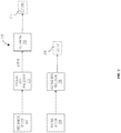
- FIG. 4 illustrates one embodiment of the frequency tracking system 300 in combination with an additional state complimentary filter that combines the output (i.e., blended frequency 312 ) of the first state complimentary filter (i.e., the frequency tracking system 300 ) with another estimate of frequency (i.e., 3rd frequency measurement 402 ).
- the additional frequency estimate (3rd frequency measurement 402 ) could come from a combination of mechanical frequency 214 and electrical frequency 208 as performed by a traditional complimentary filter (i.e., traditional complimentary filter 412 ).
- the frequency tracking system 300 may output a blended frequency 312 .
- the contribution to the estimated frequency 404 of the two measurements can be combined by employing filters with complementary frequency responses using a traditional complimentary filter 412 .
- a low-pass filter H(s) 404 may be applied to the mechanical frequency 214 .
- the complement of H(s) 404 would then be 1-H(s) 406 which realizes a high-pass filter.
- 1-H(s) 406 may be applied to the electrical frequency 208 .
- the output signals of the high pass filter and the low pass filter may be added together to create a 3rd frequency measurement 402 with different characteristics than either mechanical frequency 214 or electrical frequency 208 .
- a second set of state complimentary filter logic (i.e., B 408 and 1-B 410 ) using combination factor B 414 may be applied to merge the output f′′ 402 from this filter with the output from the state complementary filter implemented above (i.e., blended frequency f′ 312 ) and the results may be added to produce an estimated frequency f′′′ 416 .
- any number of signals may be seamlessly combined to provide the best frequency estimate.
- a variety of complementary filters could be employed that implement different frequency responses; the filters may be selected between based on the machine state or condition.
- multiple signals can be combined in a single stage by choosing a plurality of gains that sum to 1.
- the hierarchical system of FIG. 4 may be realized with the following gains, BA, B(1-A), and (1-B).
- the gains A and B could independently be derived from separate condition indicators, or as a combined condition assessment process.
- the frequency tracking system 300 blends the best of speed and stator voltage frequency measurements.
- the frequency tracking system 300 considers many aspects regarding signal quality and response.
- the frequency tracking system 300 may include a high-pass filtering for the RPM-derived frequency (i.e., mechanical frequency 214 ) as RPM accurately captures the fast transient response of frequency.
- the RPM-derived frequency does not accurately show the power angle (angle between rotor and electrical phasor).
- the frequency tracking system 300 can use the electrical angle from the electrical frequency 208 because it represents electrical angle well, except during a transient.
- the frequency tracking system 300 may use the mechanical frequency 214 during a transient and estimate the angle based on the angle of the electrical frequency 208 before the transient.
- the mechanical frequency 214 captures the fast transient response of frequency and is fault resilient.
- the frequency tracking system 300 may disregard the electrical frequency 208 information during transient or fault conditions and instead focuses on the mechanical frequency 214 information.
- the conditional logic 304 causes the frequency tracking system 300 to use the measurement most applicable via a selection approach (e.g., combination factor A 310 ).
- the estimated frequency may be stable transiently and accurate during faulted circuit conditions because of the machine speed measurement captured in the mechanical frequency 214 .
- the frequency tracking system 300 may include a processor (which may be a microprocessor, field programmable gate array (FPGA), application-specific integrated circuit (ASIC), or the like) that may be configured to coordinate one or more desired functions (e.g., measure, compare, analyze, normalize, etc.).
- a processor may perform distributed (e.g., parallel) processing to execute or otherwise implement functionalities of the present embodiments.
- a processor may run a standard operating system and perform standard operating system functions.
- the frequency tracking system 300 may further comprise a human media interface, which may include a display, an attached computer, or the like.
- the computer storage media may contain one or more input/output interfaces that facilitate HMI.
- the input device(s) may include a keyboard, mouse, button, touch screen, light pen, tablet, microphone, sensor, or other hardware with accompanying firmware and/or software.
- the output device(s) may include a monitor or other display, printer, speech or text synthesizer, switch, signal line, graphical user interface, or other hardware with accompanying firmware and/or software.
- the frequency tracking system 300 may be implemented as software modules or components.
- a software module or component may include any type of computer instruction or computer-executable code located within or on a computer-readable storage medium.
- a software module may, for instance, comprise one or more physical or logical blocks of computer instructions, which may be organized as a routine, a program, an object, a component, a data structure, etc., that perform one or more tasks or implement particular abstract data types.
- a particular software module may comprise disparate instructions stored in different locations of a computer-readable storage medium, which together implement the described functionality of the module. Indeed, a module may comprise a single instruction or many instructions, and may be distributed over several different code segments, among different programs, and across several computer-readable storage media.
- the frequency tracking system 300 may function as one or more modules.
- a module may include all or portions of other elements of the frequency tracking system 300 .
- the modules may run multiple operations concurrently or in parallel by or on one or more processors.
- Portions of the disclosed modules, components, and/or facilities are embodied as executable instructions embodied in hardware or firmware, or stored on a non-transitory, machine-readable storage medium.
- the instructions may comprise computer program code that, when executed by a processor and/or computing device, causes a computing system to implement certain processing steps, procedures, and/or operations, as disclosed herein.
- the modules, components, and/or facilities disclosed herein may be implemented and/or embodied as a driver, a library, an interface, an API, FPGA configuration data, firmware (e.g., stored on an EEPROM), and/or the like.
- Portions of the modules, components, and/or facilities disclosed herein are embodied as machine components, such as general and/or application-specific devices, including, but not limited to: circuits, integrated circuits, processing components, interface components, hardware controller(s), storage controller(s), programmable hardware, FPGAs, ASICs, and/or the like.
- the modules may be referred to as controllers, layers, services, engines, facilities, drivers, circuits, and/or the like.
- FIG. 5 illustrates a flow chart of a method 500 for tracking frequency in accordance with one embodiment.
- the method 500 may be stored on a memory as computer-executable code to be executed.
- the method 500 may be executed by a processor, IED, or other system.
- the frequency tracking system 300 as described in FIG. 3 may use the method 500 .
- a frequency tracking system may receive 502 shaft speed from a plurality of sensors.
- the frequency tracking system may convert 512 the shaft speed to a shaft-measured frequency.
- the frequency tracking system may also receive 504 stator voltage frequency from a second sensor.
- the frequency tracking system determines 506 a current operating state of the generator, and blends 508 the stator voltage frequency and the shaft-measured frequency based on the current operating state to determine a blended frequency measurement.
- the frequency tracking system provides 510 an estimated frequency based on the blended frequency measurement.
- the method may further include multiplying the stator voltage frequency by a factor to obtain a stator product, and multiplying the shaft-measured frequency by one minus the factor to obtain a shaft product.
- the frequency tracking system can sum the stator product and the shaft product.
- the factor may be determined based on the current operating state of the generator.
- the current operating state includes a transient condition and a fault condition.
- blending the stator voltage frequency and the shaft-measured frequency may include reducing an influence of the stator voltage frequency on the blended frequency measurement during the transient condition and the fault condition.
- the current operating state includes a first sensor fault condition and a second sensor fault condition.
- the frequency tracking system uses the stator voltage frequency during a first sensor fault condition as the blended frequency, and uses the shaft-measured frequency during a second sensor fault condition as the blended frequency.
- the method 500 may further include estimating a frequency slip between the shaft-measured frequency and the stator voltage frequency, and correcting a power angle of the shaft-measured frequency using the frequency slip.
- the method 500 may determine the operating state is based on a difference between the stator voltage frequency and the shaft-measured frequency.
- the terms “comprises,” “comprising,” or any other variation thereof, are intended to cover a non-exclusive inclusion, such that a process, method, article, or apparatus that comprises a list of elements does not include only those elements but may include other elements not expressly listed or inherent to such process, method, article, or apparatus.
- the terms “coupled,” “couple,” and any other variation thereof are intended to cover a physical connection, an electrical connection, a magnetic connection, an optical connection, a communicative connection, a functional connection, and/or any other connection.
- Principles of the present disclosure may be reflected in a computer program product on a tangible computer-readable storage medium having computer-readable program code means embodied in the storage medium.
- Any suitable computer-readable storage medium may be utilized, including magnetic storage devices (hard disks, floppy disks, and the like), optical storage devices (CD-ROMs, DVDs, Blu-Ray discs, and the like), flash memory, and/or the like.
- These computer program instructions may be loaded onto a general purpose computer, special purpose computer, or other programmable data processing apparatus to produce a machine, such that the instructions that execute on the computer or other programmable data processing apparatus create means for implementing the functions specified.
- These computer program instructions may also be stored in a computer-readable memory that can direct a computer or other programmable data processing apparatus to function in a particular manner, such that the instructions stored in the computer-readable memory produce an article of manufacture including instruction means which implement the function specified.
- the computer program instructions may also be loaded onto a computer or other programmable data processing apparatus to cause a series of operational steps to be performed on the computer or other programmable apparatus to produce a computer-implemented process such that the instructions which execute on the computer or other programmable apparatus provide steps for implementing the functions specified.
- a software module or component may include any type of computer instruction or computer-executable code located within a memory device and/or computer-readable storage medium.
- a software module may, for instance, comprise one or more physical or logical blocks of computer instructions, which may be organized as a routine, a program, an object, a component, a data structure, etc., that perform one or more tasks or implement particular data types.
- a particular software module may comprise disparate instructions stored in different locations of a memory device, which together implement the described functionality of the module.
- a module may comprise a single instruction or many instructions, and may be distributed over several different code segments, among different programs, and across several memory devices.
- Some embodiments may be practiced in a distributed computing environment where tasks are performed by a remote processing device linked through a communications network.
- software modules may be located in local and/or remote memory storage devices.
- data being tied or rendered together in a database record may be resident in the same memory device, or across several memory devices, and may be linked together in fields of a record in a database across a network.
- Suitable software to assist in implementing the invention is readily provided by those of skill in the pertinent art(s) using the teachings presented here and programming languages and tools, such as Java, Pascal, C++, C, database languages, APIs, SDKs, assembly, firmware, microcode, and/or other languages and tools.
- Embodiments as disclosed herein may be computer-implemented in whole or in part on a digital computer.
- the digital computer includes a processor performing the required computations.
- the computer further includes a memory in electronic communication with the processor to store a computer operating system.
- the computer operating systems may include, but are not limited to, Microsoft® Windows®, Apple® MacOS®, Disk Operating System (DOS), UNIX, IRJX, Solaris, SunOS, FreeBSD, Linux®, QNX®, ffiM® OS/2®, and so forth. Alternatively, it is expected that future embodiments will be adapted to execute on other future operating systems.
Landscapes
- Physics & Mathematics (AREA)
- General Physics & Mathematics (AREA)
- Engineering & Computer Science (AREA)
- Technology Law (AREA)
- Control Of Eletrric Generators (AREA)
- Control Of Ac Motors In General (AREA)
Abstract
Description
Claims (16)
Priority Applications (2)
| Application Number | Priority Date | Filing Date | Title |
|---|---|---|---|
| US16/601,261 US11169211B2 (en) | 2019-10-14 | 2019-10-14 | Systems, methods and apparatuses for frequency tracking |
| PCT/US2020/053355 WO2021076322A1 (en) | 2019-10-14 | 2020-09-30 | Systems, methods and apparatuses for frequency tracking |
Applications Claiming Priority (1)
| Application Number | Priority Date | Filing Date | Title |
|---|---|---|---|
| US16/601,261 US11169211B2 (en) | 2019-10-14 | 2019-10-14 | Systems, methods and apparatuses for frequency tracking |
Publications (2)
| Publication Number | Publication Date |
|---|---|
| US20210109158A1 US20210109158A1 (en) | 2021-04-15 |
| US11169211B2 true US11169211B2 (en) | 2021-11-09 |
Family
ID=75382263
Family Applications (1)
| Application Number | Title | Priority Date | Filing Date |
|---|---|---|---|
| US16/601,261 Active 2040-02-11 US11169211B2 (en) | 2019-10-14 | 2019-10-14 | Systems, methods and apparatuses for frequency tracking |
Country Status (2)
| Country | Link |
|---|---|
| US (1) | US11169211B2 (en) |
| WO (1) | WO2021076322A1 (en) |
Families Citing this family (2)
| Publication number | Priority date | Publication date | Assignee | Title |
|---|---|---|---|---|
| US20240329619A1 (en) * | 2022-03-31 | 2024-10-03 | J. Michael Shifflette | Frequency Domain Work Analysis of Machinery including Turbomachinery |
| WO2023219862A1 (en) * | 2022-05-10 | 2023-11-16 | Zygo Corporation | Data age reduction |
Citations (9)
| Publication number | Priority date | Publication date | Assignee | Title |
|---|---|---|---|---|
| US5680409A (en) * | 1995-08-11 | 1997-10-21 | Fisher-Rosemount Systems, Inc. | Method and apparatus for detecting and identifying faulty sensors in a process |
| US20040227486A1 (en) * | 2002-10-18 | 2004-11-18 | Raser Technologies, Inc. | Resonant motor system |
| US20050021302A1 (en) | 2003-06-18 | 2005-01-27 | Dimino Steven A. | System and method for proactive motor wellness diagnosis based on potential cavitation faults |
| US20050180862A1 (en) | 2003-09-11 | 2005-08-18 | Airbus France | Fixed frequency electrical generation system and corresponding control procedure |
| US6981423B1 (en) | 2002-04-09 | 2006-01-03 | Rockwell Automation Technologies, Inc. | System and method for sensing torque on a rotating shaft |
| US20060038530A1 (en) * | 2004-07-07 | 2006-02-23 | Rt Patent Company, Inc. | System and method for optimizing motor performance by varying flux |
| US20100320763A1 (en) | 2009-06-19 | 2010-12-23 | Vestas Wind Systems A/S | Method for determining a rotor position of an electrical generator in a wind turbine |
| US20160187425A1 (en) | 2013-02-28 | 2016-06-30 | Ge Jenbacher Gmbh & Co Og | Method for identifying pole slip |
| US20180076753A1 (en) | 2016-09-15 | 2018-03-15 | Schweitzer Engineering Laboratories, Inc. | Systems and methods for motor slip calculation using shaft-mounted sensors |
-
2019
- 2019-10-14 US US16/601,261 patent/US11169211B2/en active Active
-
2020
- 2020-09-30 WO PCT/US2020/053355 patent/WO2021076322A1/en not_active Ceased
Patent Citations (9)
| Publication number | Priority date | Publication date | Assignee | Title |
|---|---|---|---|---|
| US5680409A (en) * | 1995-08-11 | 1997-10-21 | Fisher-Rosemount Systems, Inc. | Method and apparatus for detecting and identifying faulty sensors in a process |
| US6981423B1 (en) | 2002-04-09 | 2006-01-03 | Rockwell Automation Technologies, Inc. | System and method for sensing torque on a rotating shaft |
| US20040227486A1 (en) * | 2002-10-18 | 2004-11-18 | Raser Technologies, Inc. | Resonant motor system |
| US20050021302A1 (en) | 2003-06-18 | 2005-01-27 | Dimino Steven A. | System and method for proactive motor wellness diagnosis based on potential cavitation faults |
| US20050180862A1 (en) | 2003-09-11 | 2005-08-18 | Airbus France | Fixed frequency electrical generation system and corresponding control procedure |
| US20060038530A1 (en) * | 2004-07-07 | 2006-02-23 | Rt Patent Company, Inc. | System and method for optimizing motor performance by varying flux |
| US20100320763A1 (en) | 2009-06-19 | 2010-12-23 | Vestas Wind Systems A/S | Method for determining a rotor position of an electrical generator in a wind turbine |
| US20160187425A1 (en) | 2013-02-28 | 2016-06-30 | Ge Jenbacher Gmbh & Co Og | Method for identifying pole slip |
| US20180076753A1 (en) | 2016-09-15 | 2018-03-15 | Schweitzer Engineering Laboratories, Inc. | Systems and methods for motor slip calculation using shaft-mounted sensors |
Non-Patent Citations (6)
| Title |
|---|
| G.C. Gant, G.J. Alves "Progress in Electronic Control of Large Diesel Engines", Transactions of the ASME, Jul. 1990, p. 280-286, vol. 112. |
| Kiyong Kim, Jeff Burnworth "Load Anticipation Feature and Its Tuning Method for a Diesel Generating Set" 2016 Clemson University Power Systems Conference (PSC), Mar. 2016. IEEE, Clemson, SC, USA. |
| Minghui Kao, John J. Moskwa "Nonlinear Diesel Engine Conlrol and Cylinder Pressure Observation" Journal of Dynamic Systems, Measurement and Control, Jun. 1995, p. 183-192, vol. 117. |
| PCT/US2020/053355 Patent Cooperation Treaty, International Search Report and Written Opinion of the International Searching Authority, dated Jan. 5, 2021. |
| Tomohiro Iwai, et al. "The Development of an Electronic Governor for the Power Generator System", SAE Technical Paper Series, Sep. 1990, Society of Automation Engineers, Inc. |
| Wenhua Liu, et al. "Integrated Optimal Control of Speed, Excitation and Load Sharing of Parallel Operating Diesel Generator Sets" IEE 2nd International Conference on Advances in Power System Control, Operation and Management, Dec. 1993, p. 142-146, IEE, Hong Kong. |
Also Published As
| Publication number | Publication date |
|---|---|
| US20210109158A1 (en) | 2021-04-15 |
| WO2021076322A1 (en) | 2021-04-22 |
Similar Documents
| Publication | Publication Date | Title |
|---|---|---|
| US10288688B2 (en) | Systems and methods for monitoring and protecting an electric power generator | |
| Berriri et al. | Easy and fast sensor fault detection and isolation algorithm for electrical drives | |
| CA2752391C (en) | Systems and methods for protection of components in electrical power delivery systems | |
| EP1435002B1 (en) | Apparatus and method for calculating of three-phase power factor | |
| US8140283B2 (en) | Independent frequency measurement and tracking | |
| US9806656B1 (en) | Fault tolerant phase current measurement for motor control systems | |
| EP2073372B1 (en) | Generator system with intelligent processing of position signal | |
| US20110241723A1 (en) | Method for monitoring a controller of a three-phase electric motor and/or the electric motor | |
| US11169211B2 (en) | Systems, methods and apparatuses for frequency tracking | |
| US8373309B2 (en) | Systems and methods for asynchronous sampling data conversion | |
| CN110061673A (en) | Motor control method and system based on Hall sensor | |
| US9966884B2 (en) | Method and device for determining the rotor position and speed of a rotating field machine | |
| US8400087B2 (en) | Method and arrangement for determining rotation speed of a motor | |
| Damdoum et al. | Detection of faulty incremental encoder in a DFIM-based variable speed pump-turbine unit | |
| JP4738274B2 (en) | Insulation monitoring apparatus and method for electrical equipment | |
| Rothenhagen et al. | Current sensor fault detection, identification, and reconfiguration for doubly fed induction generators | |
| Gálvez-Carrillo et al. | Fault detection and isolation in current and voltage sensors of doubly-fed induction generators | |
| CN108982962B (en) | Protection and measurement integrated system and method suitable for accessing multi-interval electrical quantity | |
| CN120879742A (en) | Parallel-to-off network switching control method and device for optical storage system | |
| JP2004156986A (en) | Power failure detection device | |
| Sharma et al. | Improved grid synchronization algorithm for DG system using DSRF PLL under grid disturbances | |
| CN115996003B (en) | Discrete filtering method and discrete filter for PMSM motor position redundancy processing | |
| EP4459234A1 (en) | Determining rotor electrical angle position of a wind turbine generator | |
| Liu et al. | Reduced-Current-Sensor Control for Multi-Module PMSM with Open Phase Fault Diagnosis | |
| Liu et al. | Research on Modeling and DSP-based Software Decoding of Resolver |
Legal Events
| Date | Code | Title | Description |
|---|---|---|---|
| FEPP | Fee payment procedure |
Free format text: ENTITY STATUS SET TO UNDISCOUNTED (ORIGINAL EVENT CODE: BIG.); ENTITY STATUS OF PATENT OWNER: LARGE ENTITY |
|
| AS | Assignment |
Owner name: SCHWEITZER ENGINEERING LABORATORIES, INC., WASHINGTON Free format text: ASSIGNMENT OF ASSIGNORS INTEREST;ASSIGNORS:MANSON, SCOTT M.;BLOOD, ELLERY A.;ZWEIGLE, GREGARY C.;SIGNING DATES FROM 20191108 TO 20191114;REEL/FRAME:051036/0843 |
|
| STPP | Information on status: patent application and granting procedure in general |
Free format text: NON FINAL ACTION MAILED |
|
| STPP | Information on status: patent application and granting procedure in general |
Free format text: RESPONSE TO NON-FINAL OFFICE ACTION ENTERED AND FORWARDED TO EXAMINER |
|
| STPP | Information on status: patent application and granting procedure in general |
Free format text: FINAL REJECTION MAILED |
|
| STPP | Information on status: patent application and granting procedure in general |
Free format text: RESPONSE AFTER FINAL ACTION FORWARDED TO EXAMINER |
|
| STPP | Information on status: patent application and granting procedure in general |
Free format text: NOTICE OF ALLOWANCE MAILED -- APPLICATION RECEIVED IN OFFICE OF PUBLICATIONS |
|
| STPP | Information on status: patent application and granting procedure in general |
Free format text: PUBLICATIONS -- ISSUE FEE PAYMENT VERIFIED |
|
| STCF | Information on status: patent grant |
Free format text: PATENTED CASE |
|
| MAFP | Maintenance fee payment |
Free format text: PAYMENT OF MAINTENANCE FEE, 4TH YEAR, LARGE ENTITY (ORIGINAL EVENT CODE: M1551); ENTITY STATUS OF PATENT OWNER: LARGE ENTITY Year of fee payment: 4 |