US11168709B2 - Hydraulic drive device - Google Patents
Hydraulic drive device Download PDFInfo
- Publication number
- US11168709B2 US11168709B2 US16/366,186 US201916366186A US11168709B2 US 11168709 B2 US11168709 B2 US 11168709B2 US 201916366186 A US201916366186 A US 201916366186A US 11168709 B2 US11168709 B2 US 11168709B2
- Authority
- US
- United States
- Prior art keywords
- output shaft
- hydraulic
- hydraulic block
- disposed
- body portion
- Prior art date
- Legal status (The legal status is an assumption and is not a legal conclusion. Google has not performed a legal analysis and makes no representation as to the accuracy of the status listed.)
- Active, expires
Links
Images


Classifications
-
- F—MECHANICAL ENGINEERING; LIGHTING; HEATING; WEAPONS; BLASTING
- F15—FLUID-PRESSURE ACTUATORS; HYDRAULICS OR PNEUMATICS IN GENERAL
- F15B—SYSTEMS ACTING BY MEANS OF FLUIDS IN GENERAL; FLUID-PRESSURE ACTUATORS, e.g. SERVOMOTORS; DETAILS OF FLUID-PRESSURE SYSTEMS, NOT OTHERWISE PROVIDED FOR
- F15B11/00—Servomotor systems without provision for follow-up action; Circuits therefor
- F15B11/02—Systems essentially incorporating special features for controlling the speed or actuating force of an output member
- F15B11/04—Systems essentially incorporating special features for controlling the speed or actuating force of an output member for controlling the speed
-
- G—PHYSICS
- G01—MEASURING; TESTING
- G01P—MEASURING LINEAR OR ANGULAR SPEED, ACCELERATION, DECELERATION, OR SHOCK; INDICATING PRESENCE, ABSENCE, OR DIRECTION, OF MOVEMENT
- G01P3/00—Measuring linear or angular speed; Measuring differences of linear or angular speeds
- G01P3/42—Devices characterised by the use of electric or magnetic means
- G01P3/44—Devices characterised by the use of electric or magnetic means for measuring angular speed
- G01P3/48—Devices characterised by the use of electric or magnetic means for measuring angular speed by measuring frequency of generated current or voltage
- G01P3/481—Devices characterised by the use of electric or magnetic means for measuring angular speed by measuring frequency of generated current or voltage of pulse signals
- G01P3/487—Devices characterised by the use of electric or magnetic means for measuring angular speed by measuring frequency of generated current or voltage of pulse signals delivered by rotating magnets
-
- F—MECHANICAL ENGINEERING; LIGHTING; HEATING; WEAPONS; BLASTING
- F15—FLUID-PRESSURE ACTUATORS; HYDRAULICS OR PNEUMATICS IN GENERAL
- F15B—SYSTEMS ACTING BY MEANS OF FLUIDS IN GENERAL; FLUID-PRESSURE ACTUATORS, e.g. SERVOMOTORS; DETAILS OF FLUID-PRESSURE SYSTEMS, NOT OTHERWISE PROVIDED FOR
- F15B7/00—Systems in which the movement produced is definitely related to the output of a volumetric pump; Telemotors
- F15B7/06—Details
- F15B7/08—Input units; Master units
-
- G—PHYSICS
- G01—MEASURING; TESTING
- G01P—MEASURING LINEAR OR ANGULAR SPEED, ACCELERATION, DECELERATION, OR SHOCK; INDICATING PRESENCE, ABSENCE, OR DIRECTION, OF MOVEMENT
- G01P3/00—Measuring linear or angular speed; Measuring differences of linear or angular speeds
- G01P3/42—Devices characterised by the use of electric or magnetic means
- G01P3/44—Devices characterised by the use of electric or magnetic means for measuring angular speed
-
- F—MECHANICAL ENGINEERING; LIGHTING; HEATING; WEAPONS; BLASTING
- F15—FLUID-PRESSURE ACTUATORS; HYDRAULICS OR PNEUMATICS IN GENERAL
- F15B—SYSTEMS ACTING BY MEANS OF FLUIDS IN GENERAL; FLUID-PRESSURE ACTUATORS, e.g. SERVOMOTORS; DETAILS OF FLUID-PRESSURE SYSTEMS, NOT OTHERWISE PROVIDED FOR
- F15B2211/00—Circuits for servomotor systems
- F15B2211/60—Circuit components or control therefor
- F15B2211/63—Electronic controllers
- F15B2211/6303—Electronic controllers using input signals
- F15B2211/6336—Electronic controllers using input signals representing a state of the output member, e.g. position, speed or acceleration
-
- F—MECHANICAL ENGINEERING; LIGHTING; HEATING; WEAPONS; BLASTING
- F15—FLUID-PRESSURE ACTUATORS; HYDRAULICS OR PNEUMATICS IN GENERAL
- F15B—SYSTEMS ACTING BY MEANS OF FLUIDS IN GENERAL; FLUID-PRESSURE ACTUATORS, e.g. SERVOMOTORS; DETAILS OF FLUID-PRESSURE SYSTEMS, NOT OTHERWISE PROVIDED FOR
- F15B2211/00—Circuits for servomotor systems
- F15B2211/70—Output members, e.g. hydraulic motors or cylinders or control therefor
- F15B2211/75—Control of speed of the output member
-
- F—MECHANICAL ENGINEERING; LIGHTING; HEATING; WEAPONS; BLASTING
- F15—FLUID-PRESSURE ACTUATORS; HYDRAULICS OR PNEUMATICS IN GENERAL
- F15B—SYSTEMS ACTING BY MEANS OF FLUIDS IN GENERAL; FLUID-PRESSURE ACTUATORS, e.g. SERVOMOTORS; DETAILS OF FLUID-PRESSURE SYSTEMS, NOT OTHERWISE PROVIDED FOR
- F15B7/00—Systems in which the movement produced is definitely related to the output of a volumetric pump; Telemotors
- F15B7/008—Systems in which the movement produced is definitely related to the output of a volumetric pump; Telemotors with rotary output
Definitions
- the present invention relates to a hydraulic drive device and relates particularly to a hydraulic drive device provided with a rotation sensor capable of determining a rotational speed of a motor output shaft.
- a traveling drive device of a work machine and the like there is known a hydraulic drive device provided with a rotation sensor for detecting a rotational speed (namely, the number of rotations) of a hydraulic motor.
- Japanese Patent Application Publication No. Hei 10-257815 discloses a vehicle speed detector for a grass mowing machine.
- a rotation detection mechanism for detecting rotation of an output shaft of a hydraulic motor is provided on one end side of the output shaft.
- a rotary shaft connected to the output shaft is provided so as to penetrate through a hydraulic block.
- a detection gear of the rotation detection mechanism is mounted to a part of the rotary shaft, the part protruding from the hydraulic block.
- an electromagnetic pickup mechanism is mounted to the hydraulic block on a side opposite to a side on which the hydraulic motor is provided. The electromagnetic pickup mechanism detects rotation of the detection gear that rotates integrally with the output shaft and the rotary shaft.
- the detection gear of the rotation detection mechanism and the electromagnetic pickup mechanism are mounted to a side surface of the hydraulic block so as to largely protrude from the hydraulic block with respect to an axial direction. Consequently, the drive device as a whole is increased in length in the axial direction.
- the hydraulic block in which an oil passage is formed to supply a hydraulic oil to the hydraulic motor is required to be provided adjacently to the hydraulic motor with respect to the axial direction. Furthermore, various pipes and valves are connected to a side surface of the hydraulic block on a radial direction side. For this reason, it is preferable from the viewpoint of a device configuration that the rotation sensor be provided on a side surface portion of the hydraulic block on a side opposite to the hydraulic motor with respect to the axial direction.
- the present invention has been made in view of the above-mentioned circumstances, and it is an object of the present invention to provide a hydraulic drive device configured not to be increased in length in an axial direction.
- One aspect of the present invention relates to a hydraulic drive device provided with a body portion for converting energy of a supplied pressure oil into rotational power, the body portion including an output shaft configured to rotate along a rotation axis by the rotational power, a hydraulic block disposed in an extending direction of the output shaft of the body portion and having an oil passage for supplying the pressure oil to the body portion, and a rotation sensor for detecting rotation of the output shaft, at least part of the rotation sensor being disposed in the hydraulic block.
- the body portion is disposed on one side of the hydraulic block, while the rotation sensor is disposed on the other side of the hydraulic block, an end portion of the hydraulic block on the other side has a concave portion, and at least part of the rotation sensor is disposed in the concave portion.
- the rotation sensor includes a rotary portion and a detection portion for measuring a rotational speed of said rotary portion, the rotary portion is connected to the output shaft and axially rotates together with the output shaft, and the rotation sensor determines a rotational speed of the output shaft with the detection portion measuring the rotational speed of the rotary portion.
- a connection part of the rotary portion at which the rotary portion is connected to the output shaft may be disposed in the concave portion of the hydraulic block.
- the hydraulic drive device further includes an interposition member secured to the hydraulic block, at least part of the interposition member being disposed in the concave portion of the hydraulic block, and the detection portion is secured to the hydraulic block via the interposition member.
- the output shaft includes a first connection shaft and a second connection shaft connected to each other, the second connection shaft is disposed more distantly than the first connection shaft from the body portion, and the rotary portion is connected to the second connection shaft.
- One end portion of the output shaft may be disposed in the concave portion of the hydraulic block.
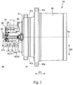
- FIG. 1 is a view showing one example of a hydraulic drive device.
- FIG. 2 is a view showing, on an enlarged scale, an internal configuration of part of an end portion of a hydraulic block shown in FIG. 1 on a side on which a rotation sensor is disposed.
- FIG. 1 is a view showing one example of a hydraulic drive device 10 .
- FIG. 1 shows an external appearance state of a body case 41 and a rotary case 42 and illustrates a device configuration in a hydraulic block 20 .
- the hydraulic drive device 10 includes a hydraulic motor 12 , the hydraulic block 20 , and a rotation sensor 30 . That is, the hydraulic drive device 10 is provided with a body portion 13 for converting energy of a supplied pressure oil into rotational power, the body portion 13 including an output shaft 14 configured to rotate along a rotation axis Ax by using the rotational power, the hydraulic block 20 disposed in an extending direction of the output shaft 14 of the body portion 13 and having an oil passage 21 for supplying the pressure oil to the body portion 13 , and the rotation sensor 30 for detecting rotation of the output shaft 14 , at least part of the rotation sensor 30 being disposed in the hydraulic block 20 .
- the hydraulic motor 12 can adopt any configuration in which the hydraulic motor 12 is driven using a hydraulic oil (namely, a pressure oil) supplied from an unillustrated hydraulic source and generates a rotational output.
- a hydraulic oil namely, a pressure oil
- a gear motor, a vane motor, or a plunger motor can be used as the hydraulic motor 12 .
- the hydraulic motor 12 of this embodiment is configured by an axial-type plunger motor and may have a configuration similar to that of the hydraulic motor disclosed by the '815 Publication.
- the hydraulic motor 12 includes the body portion 13 and the output shaft 14 .
- the body portion 13 is disposed inside each of the body case 41 and the rotary case 42 , and the output shaft 14 protrudes from the body portion 13 in a rotation axis direction D 1 and axially rotates.
- the body portion 13 convers energy of a supplied hydraulic oil into rotational power (namely, a torque). That is, the body portion 13 receives a hydraulic oil and uses it to generate rotational power.
- the output shaft 14 axially rotates about the rotation axis Ax and outputs rotational power transmitted thereto from the body portion 13 .
- the body portion 13 of the hydraulic motor 12 is disposed on one side S 1 of the hydraulic block 20 (a right side in FIG. 1 ) with respect to the rotation axis direction D 1 , which is an extending direction of the rotation axis Ax (namely, the extending direction of the output shaft 14 ).
- the rotation sensor 30 is disposed on the other side S 2 of the hydraulic block 20 (a left side in FIG. 1 ) with respect to the rotation axis direction D 1 .
- the body portion 13 of the hydraulic motor 12 as a whole is disposed inside the body case 41 and the rotary case 42 , and only part of the body portion 13 is illustrated in FIG. 1 .
- the output shaft 14 of the hydraulic motor 12 includes a first connection shaft 15 and a second connection shaft 16 .
- the first connection shaft 15 and the second connection shaft 16 are connected to each other and axially rotate integrally with each other about the rotation axis Ax.
- the second connection shaft 16 is disposed more distantly than the first connection shaft 15 from the body portion 13 of the hydraulic motor 12 and provided so as to penetrate through the hydraulic block 20 .
- the hydraulic motor 12 further includes an output shaft (hereinafter, referred to also as a “second output shaft,” unillustrated) different from the output shaft 14 (hereinafter, referred to also as a “first output shaft”) shown in FIG. 1 .
- the second output shaft is disposed inside the rotary case 42 .
- the first output shaft and the second output shaft both extend in the rotation axis direction D 1 , are connected to each other, and provided so as to be axially rotatable integrally with each other about the common rotation axis Ax.
- the first output shaft and the second output shaft protrude from the body portion 13 toward opposite directions to each other with respect to the rotation axis direction D 1 , with the first output shaft (namely, the output shaft 14 ) protruding from the body portion 13 toward the left side in FIG. 1 and the second output shaft protruding from the body portion 13 toward the right side in FIG. 1 .
- a rotational output of the second output shaft is transmitted to the rotary case 42 via a speed reducer (unillustrated) provided in the rotary case 42 . This causes the rotary case 42 to axially rotate about the rotation axis Ax.
- the rotary case 42 is connected to an endless track crawler via a sprocket (unillustrated), and said crawler is driven to rotate through axial rotation of the rotary case 42 .
- the hydraulic motor 12 may include a single output shaft instead of the first output shaft and the second output shaft mentioned above.
- the body case 41 is connected to a securing member (for example, a track frame) such as a frame of a travel machine via an external connection portion 41 a , provided separately from the rotary case 42 , and does not axially rotate.
- a securing member for example, a track frame
- the body portion 13 of the hydraulic motor 12 and the hydraulic block 20 are connected to the body case 41 , and the body case 41 securely supports the body portion 13 of the hydraulic motor 12 and the hydraulic block 20 .
- the hydraulic block 20 there are formed a plurality of oil passages 21 connected to the hydraulic motor 12 .
- a hydraulic oil used to drive the hydraulic motor 12 is caused to flow through the oil passages 21 . That is, via the oil passages 21 formed in the hydraulic block 20 , a hydraulic oil is supplied to the body portion 13 of the hydraulic motor 12 and is also discharged from said body portion 13 .
- a pipe 62 for supplying and discharging a hydraulic oil is properly connected to a side surface of the hydraulic block 20 in a radial direction D 2 , and an element (typically, a valve such as a relief valve or a shuttle valve) for controlling and blocking a flow of the hydraulic oil is disposed as required in the oil passages 21 in the hydraulic block 20 .
- the pipe 62 is secured to the side surface of the hydraulic block 20 in the radial direction D 2 via a joint member 61 (such as, for example, a split flange fitting (see Japanese Patent Application Publication No. 2015-215006)), and thus supply and discharge of a hydraulic oil at a relatively high pressure between the pipe 62 and the oil passages 21 are appropriately performed.
- a relief valve (unillustrated) may be disposed in an oil passage denoted by a reference character “ 21 a ,” and a shuttle valve (unillustrated) may be disposed in an oil passage denoted by a reference character “ 21 b .”
- the rotation sensor 30 determines a rotational speed of the output shaft 14 .
- the output shaft 14 rotates in conjunction with rotation of the crawler connected to the hydraulic drive device 10 (the rotary case 42 in this embodiment). Therefore, the rotation sensor 30 can detect a rotational speed of the crawler by determining the rotational speed of the output shaft 14 , thus functioning as a sensor for determining a traveling speed of a travel machine such as a work machine provided with said crawler.
- At least part of the rotation sensor 30 of this embodiment is disposed in a concave portion provided at an end portion of the hydraulic block 20 on the other side (the left side in FIG. 1 ).
- FIG. 2 is a view showing, on an enlarged scale, an internal configuration of part of the end portion of the hydraulic block 20 shown in FIG. 1 on a side on which the rotation sensor 30 is disposed.
- the rotation sensor 30 includes a rotary portion 32 and a detection portion 31 for measuring a rotational speed of said rotary portion 32 .
- the rotary portion 32 is connected to the second connection shaft 16 (the output shaft 14 ) and axially rotates together with the second connection shaft 16 .
- the detection portion 31 is connected to a controller (unillustrated) via a wiring portion 55 and transmits a measurement result to the controller.
- the detection portion 31 measures the rotational speed of the rotary portion 32 .
- the detection portion 31 configured by an electromagnetic pickup mechanism sequentially detects a plurality of teeth formed on an outer peripheral surface of the rotary portion 32 , thus being able to measure the rotational speed of the rotary portion 32 .
- the rotation sensor 30 makes the detection portion 31 measure the rotational speed of the rotary portion 32 and thus determines a rotational speed of the second connection shaft 16 (the output shaft 14 ).
- the rotary portion 32 and the detection portion 31 are arranged in a row in the rotation axis direction D 1 .
- the rotary portion 32 is disposed in a concave portion 22 formed in the hydraulic block 20 , and the detection portion 31 is provided so as to protrude from said concave portion 22 in the rotation axis direction D 1 .
- the end portion of the hydraulic block 20 on the other side has the concave portion 22 .
- the concave portion 22 is formed by recessing part of the end portion of the hydraulic block 20 on the other side from the other side toward one side (namely, from the left side to a right side in FIG. 2 ) and constituted by a circular columnar space.
- the concave portion 22 illustrated is provided so as to communicate with a through hole 45 of the hydraulic block 20 , in which the second connection shaft 16 extends, and the rotation axis Ax passes through a center of the concave portion 22 .
- the concave portion 22 is larger than the through hole 45 .
- a size of the concave portion 22 in the radial direction D 2 may be equal to a size of the through hold 45 in the radial direction D 2 or larger than the size of the through hole 45 in the radial direction D 2 .
- both of the detection portion 31 and the rotary portion 32 or the rotary portion 32 be disposed so as to at least partially overlap in projection with respect to the radial direction D 2 with the joint member 61 shown in FIG. 1 .
- the hydraulic drive device 10 (particularly, the hydraulic block 20 ) can be reduced in length in the rotation axis direction D 1 .
- a ring member 40 In addition to the rotary portion 32 , a ring member 40 , a bearing 50 , and one end portion of the second connection shaft 16 are disposed.
- the second connection shaft 16 extends through the through hole 45 and the concave portion 22 and is axially rotatably held by the bearing 50 .
- the one end portion of the second connection shaft 16 disposed in the concave portion 22 is connected to a sensor connection part 33 of the rotary portion 32 via a third securing member 53 such as a screw.
- the connection part 33 of the rotary portion 32 for connecting the second connection shaft 16 (the output shaft 14 ) and the rotary portion 32 together is disposed in the concave portion 22 .
- the ring member 40 is an annular interposition member disposed so as to surround the rotary portion 32 with respect to the radial direction D 2 and constitutes an intermediate member for securing the detection portion 31 to the hydraulic block 20 .
- the detection portion 31 is secured to the ring member 40 shown in FIG. 2 by use of a first securing member 51
- the ring member 40 is secured to the hydraulic block 20 by use of a second securing member 52 . That is, an annular flange part of the detection portion 31 , which protrudes in the radial direction D 2 , is secured to the ring member 40 by use of the first securing member 51 extending in the rotation axis direction D 1 .
- the ring member 40 is secured to the hydraulic block 20 by use of the second securing member 52 extending in the rotation axis direction D 1 . In this manner, the detection portion 31 is secured to the hydraulic block 20 via the ring member 40 .
- an arrangement of the detection portion 31 is adjusted utilizing an arrangement of the bearing 50 provided so as to surround the second connection shaft 16 (namely, the output shaft 14 ), and thus the detection portion 31 can be accurately adjusted to be arranged at a desired position via the ring member 40 .
- the ring member 40 shown in FIG. 2 has a plurality of different inner diameters at different positions with respect to the rotation axis direction D 1 depending on a member disposed inside thereof. Specifically, a part (a fitting portion on the one side S 1 , see a reference character “ 40 a ” in FIG.
- the ring member 40 inside which the rotary portion 32 is disposed, has an inner diameter larger than an outer diameter of the rotary portion 32 and is disposed apart from the rotary portion 32 so as not to inhibit rotation of the rotary portion 32 .
- a relative positional relationship between the part 40 a inside which the bearing 50 is disposed and the part 40 c inside which the detection portion 31 is disposed can be accurately adjusted via the ring member 40 , and thus respective cores of the detection portion 31 and the rotary portion 32 can be easily and highly accurately aligned with the rotation axis Ax.
- holes of the ring member 40 for forming the above-mentioned plurality of inner diameters be formed at a time under a predetermined condition. It is preferable that the above-mentioned parts 40 a , 40 b , and 40 c be processed at the same time so that a desired relative positional relationship among the parts 40 a , 40 b , and 40 c are maintained.
- the ring member 40 of this embodiment is provided so as to be mountable to/demountable from the hydraulic block 20 .
- a space is formed outside the rotary portion 32 in the radial direction D 2 . Said space is utilized when the rotary portion 32 (namely, the sensor connection part 33 ) and the second connection shaft 16 (namely, the output shaft 14 ) are connected together by using the third securing member 53 , and thus this connecting operation can be facilitated.
- the ring member 40 has such a shape and size as not to inhibit axial rotation of the second connection shaft 16 and the rotary portion 32 and as to be connectable to the detection portion 31 and the hydraulic block 20 . Accordingly, it is preferable that, in the concave portion 22 , the ring member 40 be disposed outward of the second connection shaft 16 and the rotary portion 32 with respect to the radial direction D 2 and provided so as to be separated from the second connection shaft 16 and the rotary portion 32 . Furthermore, it is preferable that a projection image of the detection portion 31 and a projection image of the ring member 40 with respect to the rotation axis direction D 1 at least partly overlap with each other. Furthermore, it is preferable that a projection image of the ring member 40 and a projection image of the hydraulic block 20 with respect to the rotation axis direction D 1 at least partly overlap with each other.
- first securing member 51 the second securing member 52 , and the third securing member 53 is also not particularly limited, typically, they can be each configured by a screw. Furthermore, the numbers of first securing members 51 , second securing members 52 , and third securing members 53 installed and installation positions thereof are also not particularly limited.
- the rotation sensor 30 is disposed in the concave portion 22 of the hydraulic block 20 , and thus the hydraulic drive device 10 as a whole can be decreased in length in the rotation axis direction D 1 .
- the detection portion 31 and the rotary portion 32 are partly disposed in the concave portion 22
- one or both of the detection portion 31 and the rotary portion 32 as a whole may be disposed in the concave portion 22 .
- the detection portion 31 can be appropriately secured to the hydraulic block 20 via the ring member 40 .
- the rotation sensor 30 can be easily applied to the already-existing hydraulic drive device 10 , and the drive device as a whole can also be reduced in length in the rotation axis direction D 1 .
- a commercially available rotation sensor namely, a detection portion and a rotary portion
- a rotation sensor having a preset shape and size
- the ring member 40 as a whole is disposed in the concave portion 22 , only part of the ring member 40 may be disposed in the concave portion 22 . Furthermore, while in FIG. 1 and FIG. 2 , the annular ring member 40 is provided as the interposition member between the detection portion 31 and the hydraulic block 20 , a member having any other shape than an annular shape may be provided as said interposition member.
- each of the first securing member 51 , the second securing member 52 , and the detection portion 31 protrudes from the end portion of the hydraulic block 20 on the other side (a left side end portion thereof in FIG. 1 and FIG. 2 )
- all of these members may be disposed in the concave portion 22 .
- bulging of the hydraulic block 20 from the end portion thereof on the other side can be decreased.
- the wiring portion 55 extending from the detection portion 31 so as not to protrude from the end portion of the hydraulic block 20 on the other side, bulging of the hydraulic block 20 from the end portion thereof on the other side can be decreased or eliminated.
- a groove (namely, a concave portion separate from the above-mentioned concave portion 22 ) is formed in an end surface of the hydraulic block 20 on the other side, or a hole is formed in the end portion of the hydraulic block 20 on the other side, and the wiring portion 55 is disposed in the groove or the hole.
- the wiring portion 55 can be disposed so as not to protrude from the end portion of the hydraulic block 20 on the other side.
- the ring member 40 is provided in the hydraulic drive device 10 shown in FIG. 1 and FIG. 2 , in a case where the detection portion 31 has such a shape and size as to be directly connectable to the hydraulic block 20 , the ring member 40 does not have to be provided.
- the hydraulic drive device 10 may adopt a configuration other than that in the foregoing embodiment.
- a specific object whose rotational speed is determined by the rotation sensor 30 that detects rotation of the output shaft 14 is also not limited.
Landscapes
- Engineering & Computer Science (AREA)
- Physics & Mathematics (AREA)
- Fluid Mechanics (AREA)
- Mechanical Engineering (AREA)
- General Engineering & Computer Science (AREA)
- General Physics & Mathematics (AREA)
- Hydraulic Motors (AREA)
- Motor Power Transmission Devices (AREA)
Abstract
Description
Claims (8)
Applications Claiming Priority (3)
| Application Number | Priority Date | Filing Date | Title |
|---|---|---|---|
| JP2018-072648 | 2018-04-04 | ||
| JPJP2018-072648 | 2018-04-04 | ||
| JP2018072648A JP7128642B2 (en) | 2018-04-04 | 2018-04-04 | hydraulic drive |
Publications (2)
| Publication Number | Publication Date |
|---|---|
| US20190309769A1 US20190309769A1 (en) | 2019-10-10 |
| US11168709B2 true US11168709B2 (en) | 2021-11-09 |
Family
ID=68096459
Family Applications (1)
| Application Number | Title | Priority Date | Filing Date |
|---|---|---|---|
| US16/366,186 Active 2039-08-17 US11168709B2 (en) | 2018-04-04 | 2019-03-27 | Hydraulic drive device |
Country Status (2)
| Country | Link |
|---|---|
| US (1) | US11168709B2 (en) |
| JP (1) | JP7128642B2 (en) |
Citations (14)
| Publication number | Priority date | Publication date | Assignee | Title |
|---|---|---|---|---|
| JPH10257815A (en) | 1997-03-19 | 1998-09-29 | Kensetsusho Hokurikuchihou Kensetsukyoku | Mower speed detector |
| US20020142870A1 (en) * | 2001-03-30 | 2002-10-03 | Honda Giken Kogyo Kabushiki Kaisha | Belt-type continuously variable transmission |
| US20110083553A1 (en) * | 2009-10-14 | 2011-04-14 | Michael Duerr | Hydraulic machine |
| US20110224878A1 (en) * | 2010-03-12 | 2011-09-15 | Suzuki Motor Corporation | Shift control apparatus of automatic transmission |
| US20130218429A1 (en) * | 2010-08-05 | 2013-08-22 | Toyota Jidosha Kabushiki Kaisha | Control device of continuously variable transmission for vehicle |
| US20140349816A1 (en) * | 2011-11-18 | 2014-11-27 | Jatco Ltd | Device for controlling automatic transmission and method for controlling same |
| US20150027273A1 (en) * | 2012-04-20 | 2015-01-29 | Aisin Aw Co., Ltd. | Vehicle drive device |
| US20150066312A1 (en) * | 2013-01-18 | 2015-03-05 | Komatsu Ltd. | Hydraulic excavator and method for measuring stroke of hydraulic cylinder of hydraulic excavator |
| JP2015215006A (en) | 2014-05-08 | 2015-12-03 | ブリヂストンフローテック株式会社 | Fitting |
| US20160280222A1 (en) * | 2015-03-25 | 2016-09-29 | Iseki & Co., Ltd. | Speed change control apparatus for work vehicle |
| US20170276055A1 (en) * | 2014-08-22 | 2017-09-28 | Komatsu Ltd. | Hydraulic pump/motor with rotation detection mechanism |
| US20180266551A1 (en) * | 2015-02-05 | 2018-09-20 | Hitachi Automotive Systems, Ltd. | Transmission Control System |
| US20190309798A1 (en) * | 2018-04-04 | 2019-10-10 | Nabtesco Corporation | Connecting structure and hydraulic drive device |
| US20200103011A1 (en) * | 2018-10-01 | 2020-04-02 | Kanzaki Kokyukoki Mfg. Co., Ltd. | Traveling hydraulic stepless transmission |
Family Cites Families (3)
| Publication number | Priority date | Publication date | Assignee | Title |
|---|---|---|---|---|
| JP2607135Y2 (en) * | 1993-03-12 | 2001-04-16 | 帝人製機株式会社 | Hydraulic motor with reduction gear |
| JPH11218073A (en) * | 1998-02-02 | 1999-08-10 | Komatsu Ltd | Pump / motor device |
| JP2001165102A (en) * | 1999-12-08 | 2001-06-19 | Teijin Seiki Co Ltd | Electro hydraulic servo motor |
-
2018
- 2018-04-04 JP JP2018072648A patent/JP7128642B2/en active Active
-
2019
- 2019-03-27 US US16/366,186 patent/US11168709B2/en active Active
Patent Citations (14)
| Publication number | Priority date | Publication date | Assignee | Title |
|---|---|---|---|---|
| JPH10257815A (en) | 1997-03-19 | 1998-09-29 | Kensetsusho Hokurikuchihou Kensetsukyoku | Mower speed detector |
| US20020142870A1 (en) * | 2001-03-30 | 2002-10-03 | Honda Giken Kogyo Kabushiki Kaisha | Belt-type continuously variable transmission |
| US20110083553A1 (en) * | 2009-10-14 | 2011-04-14 | Michael Duerr | Hydraulic machine |
| US20110224878A1 (en) * | 2010-03-12 | 2011-09-15 | Suzuki Motor Corporation | Shift control apparatus of automatic transmission |
| US20130218429A1 (en) * | 2010-08-05 | 2013-08-22 | Toyota Jidosha Kabushiki Kaisha | Control device of continuously variable transmission for vehicle |
| US20140349816A1 (en) * | 2011-11-18 | 2014-11-27 | Jatco Ltd | Device for controlling automatic transmission and method for controlling same |
| US20150027273A1 (en) * | 2012-04-20 | 2015-01-29 | Aisin Aw Co., Ltd. | Vehicle drive device |
| US20150066312A1 (en) * | 2013-01-18 | 2015-03-05 | Komatsu Ltd. | Hydraulic excavator and method for measuring stroke of hydraulic cylinder of hydraulic excavator |
| JP2015215006A (en) | 2014-05-08 | 2015-12-03 | ブリヂストンフローテック株式会社 | Fitting |
| US20170276055A1 (en) * | 2014-08-22 | 2017-09-28 | Komatsu Ltd. | Hydraulic pump/motor with rotation detection mechanism |
| US20180266551A1 (en) * | 2015-02-05 | 2018-09-20 | Hitachi Automotive Systems, Ltd. | Transmission Control System |
| US20160280222A1 (en) * | 2015-03-25 | 2016-09-29 | Iseki & Co., Ltd. | Speed change control apparatus for work vehicle |
| US20190309798A1 (en) * | 2018-04-04 | 2019-10-10 | Nabtesco Corporation | Connecting structure and hydraulic drive device |
| US20200103011A1 (en) * | 2018-10-01 | 2020-04-02 | Kanzaki Kokyukoki Mfg. Co., Ltd. | Traveling hydraulic stepless transmission |
Also Published As
| Publication number | Publication date |
|---|---|
| JP2019182070A (en) | 2019-10-24 |
| JP7128642B2 (en) | 2022-08-31 |
| US20190309769A1 (en) | 2019-10-10 |
Similar Documents
| Publication | Publication Date | Title |
|---|---|---|
| US10975916B2 (en) | Connecting structure and hydraulic drive device | |
| KR102124471B1 (en) | Wave gear device and hollow rotating actuator | |
| EP2589707B1 (en) | Construction machine including a swing device | |
| US7469670B2 (en) | Adjustable camshaft | |
| US9994250B2 (en) | Power steering device | |
| EP3981627B1 (en) | Axle assembly having a sensor for detecting a shift collar | |
| US9735648B2 (en) | Drive device for electric vehicle | |
| US10056802B2 (en) | Vehicle driving device | |
| JP2014206265A (en) | Wave motion gear device and hollow rotary actuator | |
| US9394810B2 (en) | Valve timing controller | |
| KR102762793B1 (en) | Motor with reducer, and construction machine | |
| US20160347352A1 (en) | Power steering apparatus | |
| US11168709B2 (en) | Hydraulic drive device | |
| US11878747B2 (en) | Speed reducer, drive unit and steering assisting device | |
| JP5557693B2 (en) | Rudder shaft fixing device of rotary vane type steering machine | |
| JPWO2019220603A1 (en) | Electric power steering device | |
| JP2014227040A (en) | Electric power steering apparatus | |
| JPH03176276A (en) | Servo valve centering device of power steering | |
| CN102678655B (en) | Fluid actuated rotating driving device | |
| JP7342591B2 (en) | Seal torque measuring device | |
| EP1171727B1 (en) | Differential lock | |
| JP2013071686A (en) | In-wheel motor driving unit | |
| JP5598085B2 (en) | Variable speed transmission unit | |
| RU2821606C1 (en) | Rotary through feed device intended, in particular, for tire pressure control | |
| KR102762798B1 (en) | Hydraulic motor |
Legal Events
| Date | Code | Title | Description |
|---|---|---|---|
| FEPP | Fee payment procedure |
Free format text: ENTITY STATUS SET TO UNDISCOUNTED (ORIGINAL EVENT CODE: BIG.); ENTITY STATUS OF PATENT OWNER: LARGE ENTITY |
|
| AS | Assignment |
Owner name: NABTESCO CORPORATION, JAPAN Free format text: ASSIGNMENT OF ASSIGNORS INTEREST;ASSIGNORS:OKADA, ISAMU;YOSHIDA, MAKOTO;SIGNING DATES FROM 20190425 TO 20190507;REEL/FRAME:049638/0791 |
|
| STPP | Information on status: patent application and granting procedure in general |
Free format text: DOCKETED NEW CASE - READY FOR EXAMINATION |
|
| STPP | Information on status: patent application and granting procedure in general |
Free format text: RESPONSE TO NON-FINAL OFFICE ACTION ENTERED AND FORWARDED TO EXAMINER |
|
| STPP | Information on status: patent application and granting procedure in general |
Free format text: FINAL REJECTION MAILED |
|
| STPP | Information on status: patent application and granting procedure in general |
Free format text: RESPONSE AFTER FINAL ACTION FORWARDED TO EXAMINER |
|
| STPP | Information on status: patent application and granting procedure in general |
Free format text: ADVISORY ACTION MAILED |
|
| STPP | Information on status: patent application and granting procedure in general |
Free format text: DOCKETED NEW CASE - READY FOR EXAMINATION |
|
| STPP | Information on status: patent application and granting procedure in general |
Free format text: NOTICE OF ALLOWANCE MAILED -- APPLICATION RECEIVED IN OFFICE OF PUBLICATIONS |
|
| STPP | Information on status: patent application and granting procedure in general |
Free format text: PUBLICATIONS -- ISSUE FEE PAYMENT VERIFIED |
|
| STCF | Information on status: patent grant |
Free format text: PATENTED CASE |
|
| MAFP | Maintenance fee payment |
Free format text: PAYMENT OF MAINTENANCE FEE, 4TH YEAR, LARGE ENTITY (ORIGINAL EVENT CODE: M1551); ENTITY STATUS OF PATENT OWNER: LARGE ENTITY Year of fee payment: 4 |