US11157482B2 - Data distribution within a failure domain tree - Google Patents
Data distribution within a failure domain tree Download PDFInfo
- Publication number
- US11157482B2 US11157482B2 US16/545,405 US201916545405A US11157482B2 US 11157482 B2 US11157482 B2 US 11157482B2 US 201916545405 A US201916545405 A US 201916545405A US 11157482 B2 US11157482 B2 US 11157482B2
- Authority
- US
- United States
- Prior art keywords
- fdl
- failure domain
- node
- failure
- nodes
- Prior art date
- Legal status (The legal status is an assumption and is not a legal conclusion. Google has not performed a legal analysis and makes no representation as to the accuracy of the status listed.)
- Active, expires
Links
Images




Classifications
-
- G—PHYSICS
- G06—COMPUTING OR CALCULATING; COUNTING
- G06F—ELECTRIC DIGITAL DATA PROCESSING
- G06F16/00—Information retrieval; Database structures therefor; File system structures therefor
- G06F16/20—Information retrieval; Database structures therefor; File system structures therefor of structured data, e.g. relational data
- G06F16/23—Updating
- G06F16/2365—Ensuring data consistency and integrity
-
- G—PHYSICS
- G06—COMPUTING OR CALCULATING; COUNTING
- G06F—ELECTRIC DIGITAL DATA PROCESSING
- G06F11/00—Error detection; Error correction; Monitoring
- G06F11/07—Responding to the occurrence of a fault, e.g. fault tolerance
- G06F11/0703—Error or fault processing not based on redundancy, i.e. by taking additional measures to deal with the error or fault not making use of redundancy in operation, in hardware, or in data representation
- G06F11/079—Root cause analysis, i.e. error or fault diagnosis
-
- G—PHYSICS
- G06—COMPUTING OR CALCULATING; COUNTING
- G06F—ELECTRIC DIGITAL DATA PROCESSING
- G06F11/00—Error detection; Error correction; Monitoring
- G06F11/07—Responding to the occurrence of a fault, e.g. fault tolerance
- G06F11/08—Error detection or correction by redundancy in data representation, e.g. by using checking codes
- G06F11/10—Adding special bits or symbols to the coded information, e.g. parity check, casting out 9's or 11's
- G06F11/1008—Adding special bits or symbols to the coded information, e.g. parity check, casting out 9's or 11's in individual solid state devices
- G06F11/1012—Adding special bits or symbols to the coded information, e.g. parity check, casting out 9's or 11's in individual solid state devices using codes or arrangements adapted for a specific type of error
- G06F11/1032—Simple parity
-
- G—PHYSICS
- G06—COMPUTING OR CALCULATING; COUNTING
- G06F—ELECTRIC DIGITAL DATA PROCESSING
- G06F11/00—Error detection; Error correction; Monitoring
- G06F11/07—Responding to the occurrence of a fault, e.g. fault tolerance
- G06F11/08—Error detection or correction by redundancy in data representation, e.g. by using checking codes
- G06F11/10—Adding special bits or symbols to the coded information, e.g. parity check, casting out 9's or 11's
- G06F11/1076—Parity data used in redundant arrays of independent storages, e.g. in RAID systems
-
- G—PHYSICS
- G06—COMPUTING OR CALCULATING; COUNTING
- G06F—ELECTRIC DIGITAL DATA PROCESSING
- G06F16/00—Information retrieval; Database structures therefor; File system structures therefor
- G06F16/20—Information retrieval; Database structures therefor; File system structures therefor of structured data, e.g. relational data
- G06F16/22—Indexing; Data structures therefor; Storage structures
- G06F16/2228—Indexing structures
- G06F16/2246—Trees, e.g. B+trees
Definitions
- the disclosure herein relates to data distribution within a failure domain tree, and further to systems, apparatus, and methods for performing and implementing such data distribution within a failure domain tree.
- One illustrative system may include a symmetric failure domain tree comprising a plurality of failure domain levels (FDL) extending from a top FDL to a bottom FD.
- Each FDL may comprise at least one node, and the top FDL may comprise a single root node.
- Each other FDL may comprise at least one node operably coupled to a node in the FDL thereabove, and each node of the bottom FDL may be a storage node to store data.
- the illustrative system may further include a controller comprising one or more processors and configured to receive a data object comprising data blocks and uniformly distribute the data blocks of the data object across the symmetric failure domain tree.
- One illustrative apparatus may include data storage hardware defining an asymmetric failure domain tree comprising a plurality of FDLs extending from a top FDL to a bottom FDL.
- Each FDL may comprise at least one node, and the top FDL may comprise a single root node.
- Each other FDL may comprise at least one node operably coupled to a node in the FDL thereabove, and each node of the bottom FDL may be a storage node to store data.
- At least one node of the asymmetric failure domain tree may be operably coupled to a different number of nodes in the FDL thereunder as any other nodes of the same FDL.
- the apparatus may further include a controller comprising one or more processors and operably coupled to the data storage hardware.
- the controller may be configured to generate a symmetric failure domain tree using the asymmetric failure domain tree, and each node of each FDL of the symmetric failure domain tree may be operably coupled to the same number of nodes in the FDL thereunder as any other nodes of the same FDL.
- An illustrative method may include receiving a data object comprising data blocks to be stored in a failure domain tree and defining a failure recovery value.
- the failure recovery value may be a maximum number of failed data blocks while being able to recover the data object.
- the failure domain tree may comprise a plurality of failure domain levels (FDL) extending from a top FDL to a bottom FDL, and each FDL may comprise at least one node and may define a failure tolerance value.
- the failure tolerance value (FTV) may be a number of nodes permitted to fail in the FDL.
- the top FDL may comprise a single root node, and each other FDL may comprise at least one node operably coupled to a node in the FDL thereabove.
- Each node of the bottom FDL may be a storage node to store data.
- the illustrative method may further include determining whether a given FDL of the FDLs would result in data object unavailability if the data object were stored within the failure domain tree and more than an FTV number of nodes of the given FDL fail.
- FIG. 1 is a diagram of an illustrative failure domain tree.
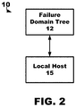
- FIG. 2 is a diagram including an illustrative device for use in data distribution within a failure domain tree.
- FIG. 3 is a diagram of an illustrative symmetric failure domain tree.
- FIG. 4 is a flow diagram of an illustrative method of data distribution into a failure domain tree.
- FIG. 5 is a diagram of an asymmetric failure domain tree being used to generate two symmetric failure domain trees.
- FIG. 6 is a diagram of an asymmetric failure domain tree being used to generate a virtual symmetric failure domain tree, and then two symmetric failure domain trees therefrom.
- FIG. 7A is a diagram of a distribution of data within an asymmetric failure domain tree.
- FIG. 7B is a diagram of a distribution of data within a symmetric failure domain tree.
- FIG. 8A is a diagram of a distribution of data within an asymmetric failure domain tree.
- FIG. 8B is a diagram of a distribution of data within a symmetric failure domain tree.
- FIG. 9 is a graph of depicting illustrative continuous distribution functions.
- a failure domain tree may be defined as data storage resources arranged, or distributed, across a storage hierarchy extending from a root level to a storage level.
- the root, or top, level may be a rack or a data center
- the storage level may be an individual data storage device such as, e.g., a disk drive (e.g., solid-state memory, hard magnetic discs, floppy discs, magnetic tapes, optical discs, integrated circuits, volatile memory, nonvolatile memory, etc.).
- Levels between the root level and the storage level may include controllers, enclosures, drawers, expanders, etc.
- a failure domains tree may be defined as a collection of various hardware resources, such as, e.g., racks, enclosures, etc., that loss of any of which can potentially cause data unavailability. Further details regarding an illustrative failure domain tree will be described herein with respect to the FIG. 1 .
- Data may be stored with a storage hierarchy according to various techniques, processes, and algorithms.
- data may be stored according to parity declustering.
- parity declustering a pool of P disks may be divided into groups, each of size G, and each group may be self-sufficient for supporting K failures within the group.
- repair scheme may lead to inferior performance of repair as well as input/output (I/O) due to following at least the reasons: repair performance is restricted by the I/O bandwidth of G-K devices, as well as by that of hot spares, any I/O on surviving disks of the affected group is hampered due to repair process, and all of the surviving disks have to participate in reconstruction of all of the failed disks.
- Parity declustering ensures that I/O bandwidth of all P-K surviving disks is utilized, which can improve the repair performance. Additionally, parity declustering may ensure that not all the surviving disks have to be involved in repair of every data block (e.g., a data block representing the basic unit of data storage) of a failed disk, which may also improve I/O performance during repair.
- every data block e.g., a data block representing the basic unit of data storage
- Parity declustering can be done if groups are formed, not at the level of disks, but at the level of blocks. Thus, each block of a disk may belong to a different group, and together the blocks may span an entire pool of P devices.
- ⁇ G - K P - K represent this ratio (i.e., surviving disks on which the recovery of a failed block depends on the total number of surviving disks). Then the rate of repair is inversely proportional to ⁇ :
- G blocks of one group consist of N data blocks, K parity blocks, and S spare blocks (e.g., spare blocks are blocks on which repaired data will be stored).
- S spare blocks e.g., spare blocks are blocks on which repaired data will be stored.
- the required tolerance at various levels of hardware objects with a data storage hierarchy e.g., listed from a top level to a bottom level: racks, enclosures, controllers, and disks
- the illustrative systems, apparatus, and methods described herein may be able to support the provided tolerances while still operating at lower ⁇ .
- K i.e., the number of parity blocks in a group
- G the maximum number of disks any one rack can hold.
- ⁇ large ⁇
- the illustrative systems, apparatus, and methods described herein may be described as supporting failure of any K in a pool of P disks, if and for that if we need at most G of the remaining (P-K) disks, then parity declustering demonstrates that maintaining a smaller ratio G/(P-K) will increase the performance of recovery.
- illustrative systems, apparatus, and methods described herein may be described as providing a way to support failures at hardware levels higher than the storage, or disk, level such as, e.g., controllers, enclosures, racks, controllers, etc., and also operating at a lower ratio of G/(P-K).
- the illustrative systems, apparatus, and methods may be able to achieve resilience across the hierarchy of hardware domains without affecting recovery performance.
- hardware resources may form, or define, a failure domain tree, or hierarchy, and each level of failure domain tree may represent one type of hardware resource.
- the disks may be at the lowest, or leaf, level of the failure domain tree.
- a tolerance vector, or value, and a size of the height of failure domain tree may be provided, e.g., by a user.
- Each tolerance vector, or value represents the expected failures to be supported at that level in the failure domain tree. For example, at an enclosure level of a failure domain tree, the tolerance vector may be two representing that two enclosures of the enclosure level may be expected to fail.
- the illustrative systems, apparatus, and methods may be described as “chopping” a data into a collection of data objects or parity groups.
- Each data object, or parity group may consist of file data along with parities calculated over that data.
- the file data and parities of the data object are then distributed through a failure domain tree.
- a mechanism, or process may be used to decide how to distribute the data blocks of these data objects, and which hardware resources to use for each data object.
- each data object or parity group may generally include data blocks, parity blocks, and spare blocks.
- the amount of parity blocks of a data object, or parity group may be referred to as a failure recovery value.
- the illustrative systems, apparatus, and methods may be further described as providing failure domain trees that support data object resilience for failure of hardware objects of a storage tree including but not restricted to racks, enclosures, controllers, and disks.
- the failure domain tree 12 extends from a top failure domain level (FDL) 20 to a bottom FDL 28 .
- root is the top FDL 20 and a plurality of data storage devices, or disks, d 0 . . . d D-1 is the bottom FDL 28 .
- the root of the top FDL 20 may represent the highest level, single point of contact for the failure domain tree 12 .
- the root of the top FDL 20 may be the point in the failure domain tree 12 were all data requests (e.g., writes, reads, etc.) flow through.
- the root of the top FDL 20 may be a virtual root.
- a rack failure domain level 22 including, for example, a plurality of data storage racks r 0 . . . r R-1 , each operably coupled to a plurality of enclosures; an enclosure failure domain level 24 including, for example, a plurality of data storage enclosures, each operably coupled to a plurality of data storage devices (only the enclosures e 0 . . . e E-1 operably coupled to rack r 0 are depicted for simplicity); and a data storage device failure domain level 28 including, for example, a plurality of data storage devices (only the data storage devices d 0 . . . d D-1 operably coupled to enclosure e 1 are depicted for simplicity).
- each FDL of the failure domain trees described herein may be referred to as nodes.
- the root is a node
- the data storage racks r 0 . . . r R-1 are nodes
- data storage enclosures e 0 . . . e E-1 are nodes
- the data storage devices d 0 . . . d D-1 are nodes.
- each FDL may include at least one node operably coupled to a node in the FDL thereabove.
- the data storage device FDL 28 includes a plurality of the data storage devices d 0 . . .
- the enclosure FDL 24 includes a plurality of the enclosures e 0 . . . e E-1 operably coupled to a node, i.e., a rack r 0 .
- the bottom FDL, the data storage device FDL 28 may be configured to be the node level where data is stored.
- Each of the FDLs may define a failure tolerance value, which may be represented by the K value located on the left side of the FDL in FIG. 1 .
- the illustrative systems, apparatus, and methods may include distributing a plurality of data blocks of a data object across each FDL in such a way to provide tolerance K at each FDL.
- a plurality of data blocks of a data object may be distributed across a number of racks in such a way to provide a prescribed failure tolerance value K r at the rack FDL 22 .
- incoming data blocks, or units are distributed into enclosures in such a way to provide a prescribed failure tolerance value K E at the rack FDL 24 .
- a data object, or parity group can potentially have data blocks from disks spanning different hardware domains.
- the illustrative system 10 may include a failure domain tree 12 operably coupled to a local host 15 , e.g., for transferring data therebetween, as shown in FIG. 2 .
- the local host 15 may request data from the failure domain tree 12 , and the failure domain tree 12 may provide such requested data to the local host 15 or the local host 15 may send data to the failure domain tree 12 to be stored.
- the local host 15 is a computer (such as, e.g., a personal computer, server, etc.).
- the systems, apparatus, and methods disclosed herein may be generally described in the context of illustrative system 10 and/or systems such as system 10 including a failure domain tree 12 , but that should in no way be taken as limiting the scope of the present disclosure.
- the failure domain tree 12 may be defined as a set of hardware resources arranged in a hierarchy from a top level to a bottom level configured to store data across a plurality of data storage devices, which may comprise the bottom level of the hierarchy. An illustrative failure domain tree 12 is described herein with reference to FIG. 1 .
- the illustrative systems, apparatus, and methods may be executed, or performed, by one or more processors.
- the processors may include various circuitry, logic, memory, etc. for use in the generating and using failure domain trees, storing data, reading data, etc.
- the processors may include one or more circuit components such as integrated circuits, processors, etc. that may be part of the system 10 (e.g., part of the failure domain tree 12 , part of the local host 15 , etc.).
- processors including one or more microprocessors, DSPs, ASICs, FPGAs, or any other equivalent integrated or discrete logic circuitry, as well as any combinations of such components.
- processors including one or more microprocessors, DSPs, ASICs, FPGAs, or any other equivalent integrated or discrete logic circuitry, as well as any combinations of such components.
- processing apparatus processor
- processor or “processing circuitry” may generally refer to any of the foregoing logic circuitry, alone or in combination with other logic circuitry, or any other equivalent circuitry.
- Such hardware, software, and/or firmware may be implemented within the same device or within separate devices to support the various operations and functions described in this disclosure.
- any of the described units, modules, or components may be implemented together or separately as discrete but interoperable logic devices. Depiction of different features as modules or units is intended to highlight different functional aspects and does not necessarily imply that such modules or units must be realized by separate hardware or software components. Rather, functionality associated with one or more modules or units may be performed by separate hardware or software components, or integrated within common or separate hardware or software components.
- the functionality ascribed to the systems, devices, and techniques described in this disclosure may be embodied as instructions on a computer-readable medium such as RAM, ROM, NVRAM, EEPROM, FLASH memory, STRAM, RRAM, magnetic data storage media, optical data storage media, or the like.
- the instructions may be executed by one or more processors to support one or more aspects of the functionality described in this disclosure.
- a controller comprising one or more processors to execute, or perform, the illustrative methods, processes, and algorithms described herein may be part of, or included with, one or more of the local host 15 , the failure domain tree 12 , and any other part of the system 10 not depicted in FIG. 2 .
- a data object which may also be referred to as a parity group, may be defined as a group of data blocks that contains data blocks, parity blocks, and spare blocks.
- a failure domain tree (FDT) may be symmetric and described as being a symmetric FDT if all nodes at the same failure domain level have a same number of children nodes.
- a FDT may be asymmetric and described as being an asymmetric FDT if the failure domain tree is not symmetric.
- the illustrative systems, apparatus, and methods may be described in terms of a Constraint A and a Claim B.
- the Constraint A includes distributing n data blocks over b buckets such that for any number, k, ⁇ b, the sum of data blocks across the first k buckets (in descending order of data blocks held) is minimum.
- An illustrative case may be when a group of data blocks is distributed over a set of disks, and there is no other failure domain to be considered. If this group of data blocks is distributed uniformly over these disks and if the required tolerance for disks is K D , then the illustrative methods and processes may only need to check if the sum of the data blocks in first K D disks (when ordered descending) is less than or equal to K, which is the parity data blocks present in a single data object or parity group. This is because the Claim B guarantees that the uniform distribution will have the minimum sum of blocks over the first K D disks.
- An illustrative symmetric failure domain tree 30 is depicted in FIG. 3 .
- the illustrative systems, apparatus, and methods may start with the root having G data blocks to distribute, and each node may uniformly distribute the data blocks it receives from its parent among its children. Once this distribution is over, one can order nodes at each level in descending order of data blocks they hold, then the failure tolerance level, K L , may be checked to determine if it, K L , results in a number of failed data blocks that exceeds K, the number of parity blocks in a group also referred to as the failure recovery value.
- K L failures at that FDL can be satisfied. In other words, if failure of K L nodes would result in a number of failed data blocks that exceeds K, then K L failures at that FDL cannot be satisfied.
- racks, enclosures, controllers, and disks are represented by r, e, c, and d, respectively, and the required failure tolerance levels, K r , K e , K c , and K d of each FDL are shown on the left side.
- the number of data blocks each node receives from its parent node is indicated above each node.
- all 8 data blocks are received from its parent, i.e., root.
- FIG. 4 An illustrative method 40 of data distribution into a failure domain tree is depicted in FIG. 4 .
- the method 40 may receive a data object 42 , e.g., from the local host 15 , to be stored in a failure domain tree such as depicted in FIGS. 2-3 .
- the method 40 may then determine if the failure domain tree is symmetric 44 to determine whether the failure domain tree should be modified, or adjusted, to provide a symmetric failure domain tree.
- a failure domain tree may be symmetric and described as being a symmetric failure domain tree if all nodes at the same level have a same number of children nodes, and a failure domain tree may be asymmetric and described as being an asymmetric failure domain tree if the failure domain tree is not symmetric.
- the method 40 may proceed to generating a symmetric failure domain tree 46 as will be further described herein with respect to FIGS. 5-6 . If it determined that the failure domain tree upon which the data object is to be stored is symmetric 44 or a symmetric failure domain tree has been generated 46 , then the method 40 may proceed to distributing the data blocks uniformly into the symmetric failure domain tree 48 .
- Uniformly distributing the data blocks of the data object across the symmetric failure domain tree 48 may be performed in a few different ways.
- the illustrative systems, apparatus, and methods may distribute data blocks uniformly according to a Constraint A and a Claim B.
- the Constraint A may include distributing n data blocks over b buckets (e.g., each level of the FDT, the lowest level in the FDT, etc.) such that for any number, k, ⁇ b, the sum of data blocks across the first k buckets (in descending order of data blocks held) is minimum.
- the illustrative systems, apparatus, and methods may, for each failure domain level of a failure domain tree, distribute an equal number of data blocks to each node within the failure domain level if a number of data blocks (G) is evenly divisible by a number of nodes of a FDL. Further, for each FDL of a FDT, if a number of data blocks (G) is not evenly divisible by a number of nodes of a FDL, an equal number of data blocks may be distributed to each node within the FDL and then each data block of the remaining data blocks may be distributed uniformly to a different node within the FDL until no data blocks are remaining.
- the “buckets” may represent the nodes at each FDL of a FDT.
- the “buckets” are the data storage devices (e.g., disk drives).
- the data storage devices e.g., disk drives.
- G 26 data blocks
- the failure domain tree includes 12 storage devices in the lowest level, then 10 storage devices would receive and store two data blocks and two storage devices would receive and store three data blocks.
- the method 40 may include determining whether failure domain level would result in data object unavailability according to the failure tolerance value of the failure domain level if the data object were stored within the failure domain tree 50 . This process 50 may occur prior to, after, or when the data object being stored within the failure domain tree.
- each of the failure domain levels may define a failure tolerance value that represents failure tolerance of the nodes of the failure domain level.
- the failure tolerance value may be defined as four, which indicates that the failure tolerance of the storage device failure domain level is four storage devices.
- the hardware of the storage device failure domain level is prescribed to have a tolerance of four storage device failures (which results in unavailability of data from such failed storage devices).
- the failure tolerance value may be defined as two, which indicates that the failure tolerance of the enclosure failure domain level is two enclosures.
- the hardware of the enclosure failure domain level is prescribed to have a tolerance of two enclosure failures (which results in unavailability of all data from such failed enclosures).
- a symmetric tree is generated, or “factored off,” a given asymmetric tree.
- the data objects, or parity groups are distributed over this symmetric failure domain tree that was generated, or “factored out,” in the first stage. It is be understood that there are various ways in which a symmetric tree can be generated from an asymmetric tree, a few illustrative ways of which are described herein.
- FIGS. 5-6 Illustrative examples of generating symmetric failure domain trees from asymmetric failure domain trees are depicted in FIGS. 5-6 .
- One process, or way, of generating symmetric failure domain trees from asymmetric failure domain trees may be described as a “tune node degrees to the least degree node,” which is depicted in FIG. 5 .
- the node with the least number of children may be considered, and the number of children of such node may be d L .
- d L For other nodes at that “child” level, only d L children may be “kept” by each parent to provide, or generate, the symmetric tree.
- a minimum number of nodes in the FDL that are operably coupled to a same node in the FDL thereabove may be determined. Then, any nodes in the FDL exceeding the minimum number that is operably coupled to a same node in the FDL thereabove may be removed from the failure domain tree.
- Such processes, or methods, can lead to a large number of possible symmetric trees.
- Such symmetric failure domain trees can be pre-generated, and the files/objects created on the system can be assigned any one of the pre-generated symmetric trees, or such symmetric failure domain trees can be generated on-demand.
- an asymmetric failure domain tree 60 may be provided and two symmetric failure domain trees 62 , 64 may be generated therefrom.
- the asymmetric failure domain tree 60 includes two failure domain levels below root, and is asymmetric because the two nodes, r 0 and r 1 , at the same level, do not have the same number of children nodes.
- r 0 has one child node, i.e., e 0
- r 1 has two child nodes, i.e., e 1 , e 2 .
- the symmetric failure domain trees 62 , 64 may be generated, or “factored out,” by determining the minimum number of children at the nodes r 0 , r 1 level is 1 as r 0 includes, or is operably coupled to, a single child node, i.e., e 0 .
- the number of children nodes “kept” by each of the nodes r 0 , r 1 in the symmetric failure domain trees 62 , 64 is one.
- the node r 1 of the first symmetric failure domain tree 62 kept one of its child nodes, e 1 , while removing its other child node, e 2 .
- the node r 1 of the second symmetric failure domain tree 64 did the opposite of the first symmetric failure domain tree 62 ; that is, the node r 1 kept one of its child nodes, e 2 , while removing its other child node, e 1 .
- Another process, or way, of generating symmetric failure domain trees from asymmetric failure domain trees may be described as a “bottom-up method” in which starting from the penultimate level, the node causing the asymmetry can be taken away from the level.
- the node causing the asymmetry can be taken away from the level.
- Another process, or way, of generating symmetric failure domain trees from asymmetric failure domain trees may include generating one or more virtual symmetric failure domain trees using the asymmetric failure domain tree, and then generating one or more symmetric failure domain trees using the one or more virtual symmetric failure domain trees as shown in FIG. 6 .
- Virtual symmetric failure domain trees may be referred to as “virtual” because virtual symmetric failure domain trees do not exist in actual hardware resources (e.g., racks, enclosures, storage devices, etc.), and instead, are virtual constructs about which hardware resources can be mapped thereto.
- a virtual symmetric tree is constructed using “tune node degrees to the least degree node” process.
- this virtual symmetric tree will have all nodes at level L with degree d L .
- the actual mapping between nodes from the input asymmetric failure domain tree and this virtual failure domain tree may take place using one or more processes that use the data object index as input.
- an asymmetric failure domain tree 60 is provided (same as depicted in FIG. 5 ) and a virtual symmetric failure domain tree 66 is generated therefrom using the same processes described herein with respect to FIG. 5 , e.g., tuning the degree of nodes to the least degree node of the same level.
- the virtual nodes of the virtual symmetric failure domain tree 66 are designated by prime symbols to indicate that such nodes are not representative of actual, hardware resources, and are instead a virtual construct.
- two possible failure domain trees 68 , 70 using actual, hardware resources can be generated using the virtual symmetric tree 66 .
- actual hardware resources may be mapped to the virtual symmetric tree 66 .
- the symmetric failure domain tree 68 maps e′ 1 from the virtual failure domain tree 66 to e 1
- the failure domain tree 70 maps e′ 1 from the virtual failure domain tree 66 to e 2 .
- two symmetric failure domain trees 68 , 70 are generated using actual hardware resources using the virtual symmetric tree 66 . In one or more embodiments, such generation can be done at run-time.
- FIGS. 7A-7B and FIGS. 8A-8B provide illustrative examples of storage of data objects into failure domain trees using various data distribution processes.
- FIGS. 7A-7B utilize an asymmetric failure domain tree 72 having, or defining, three failure domain levels including a root level at level 0 (in other words, a tree with the height of two from root).
- the failure domain tree 72 includes three nodes (a, b, c)
- the failure domain tree 72 includes ten nodes (a 0 , a 1 , a 2 , a 3 , b 0 , b 1 , b 2 , c 0 , c 1 , c 2 ).
- the data object 74 is distributed as per the underlying asymmetry of the failure domain tree 72 .
- Node a receives four data blocks as it has that many child nodes, and the same logic applies to node b and node c as each receives three data blocks (the number of data blocks received, or distributed to, each node at failure domain level 1 is indicated numerically to the right of the node).
- all nodes pass on a single data block unit per child, and in the end, all leaf nodes at failure domain level 2 contain one data block or unit (the number of data blocks received, or distributed to, each node at level 2 is indicated numerically below the node).
- the data distribution processes depicted in FIG. 7B utilize the illustrative systems, apparatus, and methods to store the data object into a failure domain tree that is symmetric. More specifically, node a 3 of failure domain level 2 is “factored out,” or removed, from the asymmetric failure domain tree to provide a symmetric failure domain tree 76 (node a 3 of failure domain level 2 is depicted using dotted lines to indicate its removal).
- each of the root's child nodes i.e., nodes a, b, c
- nodes a, b, c When distributing the ten data blocks of the data object 74 into the symmetric failure domain tree 76 , one of the three nodes a, b, or c at failure domain level 1 would receive four data blocks, and the remaining nodes at failure domain level 1 will receive three data blocks each (the number of data blocks received, or distributed to, each node at failure domain level 1 is indicated numerically to the right of the node).
- node a has received four data blocks, and thus, in this symmetric failure domain tree, at least one leaf node a 0 of failure domain level 2 receives two data blocks of the data object 74 (the number of data blocks received, or distributed to, each node at failure domain level 2 is indicated numerically below the node).
- level 1 could be skipped altogether and it may be assumed that its descendants are directly connected to the root or level 0 . This is so because if it is impossible to achieve any non-zero tolerance for a given level, then it is impossible to achieve any non-zero tolerance for any of the levels above.
- Such illustrative technique may be utilized by any level other than the root level.
- FIGS. 8A-8B utilize an asymmetric failure domain tree 82 having, or defining, three failure domain levels including a root level at failure domain level 0 (in other words, a tree with the height of two from root).
- the failure domain tree 82 includes three nodes (a, b, c), and at failure domain level 2 , the failure domain tree 82 includes nine nodes (a 0 , a 1 , a 2 , a 3 , b 0 , b 1 , b 2 , c 0 , c 1 ).
- the data object 84 is distributed as per the underlying asymmetry of the failure domain tree 82 .
- Node a receives four data blocks as it has, or is operably coupled to, that many child nodes therebelow
- node b receives three data blocks as it has, or is operably coupled to, that many children nodes therebelow
- node c receives two data blocks as it has, or is operably coupled to, that many children nodes therebelow (the number of data blocks received, or distributed to, each node at failure domain level 1 is indicated numerically to the right of the node).
- all nodes pass on a single data block unit per child, and in the end, all leaf nodes at failure domain level 2 contain one data block or unit (the number of data blocks received, or distributed to, each node at failure domain level 2 is numerically indicated to below the node).
- the data distribution processes depicted in FIG. 8B utilize the illustrative systems, apparatus, and methods to store the data object into a failure domain tree that is symmetric. More specifically, node a 2 , node a 3 , and node b 2 of failure domain level 2 are “factored out,” or removed, from the asymmetric failure domain tree to provide a symmetric failure domain tree 86 (node a 2 , node a 3 , and node b 2 of failure domain level 2 are depicted using dotted lines to indicate its removal).
- each of the root's child nodes i.e., nodes a, b, c
- nodes a, b, c have, or are operably coupled to, two nodes below them.
- each of the three nodes a, b, or c at failure domain level 1 receive three data blocks (the number of data blocks received, or distributed to, each node at failure domain level 1 is numerically indicated to the right of the node). Since each node at failure domain level 1 includes two child nodes and received three data blocks, one child node receives two data blocks and the other receives one data block (the number of data blocks received, or distributed to, each node at failure domain level 2 is numerically indicated below the node).
- node a 0 receives two data blocks of the data object 84 and node a 1 receives one data block of the data object 84 .
- Coupled refers to elements being attached to each other either directly (in direct contact with each other) or indirectly (having one or more elements between and attaching the two elements). Either term may be modified by “operatively” and “operably,” which may be used interchangeably, to describe that the coupling or connection is configured to allow the components to interact to carry out at least some functionality (for example, a controller may be operably coupled to a storage device to transfer data therebetween).
- references to “one embodiment,” “an embodiment,” “certain embodiments,” or “some embodiments,” etc. means that a particular feature, configuration, composition, or characteristic described in connection with the embodiment is included in at least one embodiment of the disclosure. Thus, the appearances of such phrases in various places throughout are not necessarily referring to the same embodiment of the disclosure. Furthermore, the particular features, configurations, compositions, or characteristics may be combined in any suitable manner in one or more embodiments.
- phrases “at least one of,” “comprises at least one of,” and “one or more of” followed by a list refers to any one of the items in the list and any combination of two or more items in the list.
- FIGS. 1-9 Illustrative systems, apparatus, and methods were described with reference to FIGS. 1-9 . It is apparent to one skilled in the art that elements or processes from one embodiment may be used in combination with elements or processes of the other embodiments, and that the possible embodiments of such systems, apparatus, and methods using combinations of features set forth herein is not limited to the specific embodiments shown in the figures and/or described herein. Further, it will be recognized that timing of the processes and the size and shape of various elements herein may be modified but still fall within the scope of the present disclosure, although certain timings, one or more shapes and/or sizes, or types of elements, may be advantageous over others.
Landscapes
- Engineering & Computer Science (AREA)
- Theoretical Computer Science (AREA)
- Physics & Mathematics (AREA)
- General Engineering & Computer Science (AREA)
- General Physics & Mathematics (AREA)
- Quality & Reliability (AREA)
- Data Mining & Analysis (AREA)
- Databases & Information Systems (AREA)
- Biomedical Technology (AREA)
- Health & Medical Sciences (AREA)
- Computer Security & Cryptography (AREA)
- Software Systems (AREA)
- Information Retrieval, Db Structures And Fs Structures Therefor (AREA)
Abstract
Description
represent this ratio (i.e., surviving disks on which the recovery of a failed block depends on the total number of surviving disks). Then the rate of repair is inversely proportional to λ:
Equality being held only at x=0 and x=X.
Claims (19)
Priority Applications (2)
| Application Number | Priority Date | Filing Date | Title |
|---|---|---|---|
| CN202010080603.2A CN111522675B (en) | 2019-02-05 | 2020-02-05 | Data allocation within fault domain trees |
| EP20155662.8A EP3693858A3 (en) | 2019-02-05 | 2020-02-05 | Data distribution within a failure domain tree |
Applications Claiming Priority (3)
| Application Number | Priority Date | Filing Date | Title |
|---|---|---|---|
| RURU20195103210 | 2019-02-05 | ||
| RU2019103210 | 2019-02-05 | ||
| RU2019103210 | 2019-02-05 |
Publications (2)
| Publication Number | Publication Date |
|---|---|
| US20200250173A1 US20200250173A1 (en) | 2020-08-06 |
| US11157482B2 true US11157482B2 (en) | 2021-10-26 |
Family
ID=71838073
Family Applications (1)
| Application Number | Title | Priority Date | Filing Date |
|---|---|---|---|
| US16/545,405 Active 2040-01-21 US11157482B2 (en) | 2019-02-05 | 2019-08-20 | Data distribution within a failure domain tree |
Country Status (2)
| Country | Link |
|---|---|
| US (1) | US11157482B2 (en) |
| CN (1) | CN111522675B (en) |
Families Citing this family (1)
| Publication number | Priority date | Publication date | Assignee | Title |
|---|---|---|---|---|
| CN115242819B (en) * | 2022-07-22 | 2024-07-16 | 济南浪潮数据技术有限公司 | Routing method for distributed storage and related components |
Citations (10)
| Publication number | Priority date | Publication date | Assignee | Title |
|---|---|---|---|---|
| US20150188978A1 (en) * | 2013-12-30 | 2015-07-02 | Microsoft Corporation | Hierarchical organization for scale-out cluster |
| US20150355971A1 (en) | 2014-06-09 | 2015-12-10 | International Business Machines Corporation | Failure domain based storage system data stripe layout |
| US20160349993A1 (en) * | 2015-05-29 | 2016-12-01 | Cisco Technology, Inc. | Data-driven ceph performance optimizations |
| WO2017068438A1 (en) | 2015-10-20 | 2017-04-27 | International Business Machines Corporation | Concurrent bulk processing of tree-based data structures |
| US20170147458A1 (en) * | 2015-11-20 | 2017-05-25 | International Business Machines Corporation | Virtual Failure Domains for Storage Systems |
| US20170255530A1 (en) | 2016-03-07 | 2017-09-07 | International Business Machines Corporation | User-defined failure domains for software-defined storage systems |
| US20180285002A1 (en) | 2016-05-11 | 2018-10-04 | Hitachi, Ltd. | Data storage system, process and computer program for such data storage system for reducing read and write amplifications |
| US20190050301A1 (en) * | 2017-08-10 | 2019-02-14 | Rubrik, Inc. | Chunk allocation |
| US20190235775A1 (en) * | 2018-01-31 | 2019-08-01 | Salesforce.Com, Inc. | Techniques for implementing fault domain sets |
| US20200226146A1 (en) * | 2019-01-16 | 2020-07-16 | Walmart Apollo, Llc | System and method for high-availability in a distributed computing environment including multiple availability zones |
Family Cites Families (2)
| Publication number | Priority date | Publication date | Assignee | Title |
|---|---|---|---|---|
| US9678839B2 (en) * | 2014-09-12 | 2017-06-13 | Microsoft Technology Licensing, Llc | Scalable data storage pools |
| CN108540315B (en) * | 2018-03-28 | 2021-12-07 | 新华三技术有限公司成都分公司 | Distributed storage system, method and device |
-
2019
- 2019-08-20 US US16/545,405 patent/US11157482B2/en active Active
-
2020
- 2020-02-05 CN CN202010080603.2A patent/CN111522675B/en active Active
Patent Citations (10)
| Publication number | Priority date | Publication date | Assignee | Title |
|---|---|---|---|---|
| US20150188978A1 (en) * | 2013-12-30 | 2015-07-02 | Microsoft Corporation | Hierarchical organization for scale-out cluster |
| US20150355971A1 (en) | 2014-06-09 | 2015-12-10 | International Business Machines Corporation | Failure domain based storage system data stripe layout |
| US20160349993A1 (en) * | 2015-05-29 | 2016-12-01 | Cisco Technology, Inc. | Data-driven ceph performance optimizations |
| WO2017068438A1 (en) | 2015-10-20 | 2017-04-27 | International Business Machines Corporation | Concurrent bulk processing of tree-based data structures |
| US20170147458A1 (en) * | 2015-11-20 | 2017-05-25 | International Business Machines Corporation | Virtual Failure Domains for Storage Systems |
| US20170255530A1 (en) | 2016-03-07 | 2017-09-07 | International Business Machines Corporation | User-defined failure domains for software-defined storage systems |
| US20180285002A1 (en) | 2016-05-11 | 2018-10-04 | Hitachi, Ltd. | Data storage system, process and computer program for such data storage system for reducing read and write amplifications |
| US20190050301A1 (en) * | 2017-08-10 | 2019-02-14 | Rubrik, Inc. | Chunk allocation |
| US20190235775A1 (en) * | 2018-01-31 | 2019-08-01 | Salesforce.Com, Inc. | Techniques for implementing fault domain sets |
| US20200226146A1 (en) * | 2019-01-16 | 2020-07-16 | Walmart Apollo, Llc | System and method for high-availability in a distributed computing environment including multiple availability zones |
Non-Patent Citations (4)
| Title |
|---|
| European Search Report from EP Application No. 20155662.8 dated Jun. 25, 2020, 13 pages. |
| Holland, et al., "Parity Declustering for Continuous Operation in Redundant Disk Arrays", 1992, Proceedings of the 5th Conference on Architectural Support for Programming Languages and Operating Systems, APLOS V, Oct. 12-15, 1992, Boston Massachusetts, 13 pages. Available online at <www.pdl.cmu.edu/ftp/Declustering/ASPLOS.pdf>. Retrieved from the Internet Aug. 20, 2019. |
| Muntz, et al., "Performance Analysis of Disks Arrays Under Failure", Proceedings of the 16th VLDB Conference, McLeod et al., editors. 16th International Conference on Very Large Data Bases, Aug. 13-16, 1990, Brisbane Australia, pp. 162-173. Available online at <https://pdfs.semanticscholar.org/5d79/6dce6ad1ab03522026f08b78a864470c51de.pdf>. Retrieved from the Internet Aug. 20, 2019. |
| Poitras, The Nutanix Bible, 2019, 367 pages (if printed to PDF format). Available online at <http://nutanixbible.com/#anchor-erasure-coding-71>. Online reference, updated periodically. Title page, Table of Contents and Foreword retrieved from the Internet on Aug. 20, 2019. 14 pages. |
Also Published As
| Publication number | Publication date |
|---|---|
| US20200250173A1 (en) | 2020-08-06 |
| CN111522675A (en) | 2020-08-11 |
| CN111522675B (en) | 2024-04-05 |
Similar Documents
| Publication | Publication Date | Title |
|---|---|---|
| US9582363B2 (en) | Failure domain based storage system data stripe layout | |
| US7681105B1 (en) | Method for lock-free clustered erasure coding and recovery of data across a plurality of data stores in a network | |
| US10019192B2 (en) | Policy-based hierarchical data protection in distributed storage | |
| CN101971168B (en) | Dynamically quantifying and improving the reliability of distributed data storage systems | |
| US7308532B1 (en) | Method for dynamically implementing N+K redundancy in a storage subsystem | |
| US20040064638A1 (en) | Integration of a RAID controller with a disk drive module | |
| US7565569B2 (en) | Data protection in a mass storage system | |
| US10353787B2 (en) | Data stripping, allocation and reconstruction | |
| US20160342360A1 (en) | Raid random distribution scheme | |
| US9519542B2 (en) | Storage control device and storage control method | |
| US11748197B2 (en) | Data storage methods and systems | |
| US20200278913A1 (en) | Policy-based hierarchical data protection in distributed storage | |
| US20210117104A1 (en) | Storage control device and computer-readable recording medium | |
| US20200250173A1 (en) | Data distribution within a failure domain tree | |
| US9811280B2 (en) | Efficient method of combining parity groups for uniform load distribution and maximizing parallelization in parity de-clustered and sliced disk raid architecture | |
| CN101571820A (en) | Redundancy protected method, device and system | |
| US9524213B2 (en) | Storage control apparatus, recording medium having stored therein storage control program and storage control method | |
| Seo et al. | Efficient disk replacement and data migration algorithms for large disk subsystems | |
| EP3693858A2 (en) | Data distribution within a failure domain tree | |
| US9785364B2 (en) | Increasing data storage reliability in a heterogeneous storage system | |
| CN108780411B (en) | Autonomous Parity Swapping in Data Storage Systems | |
| CN114168064A (en) | Method, apparatus and computer program product for rebuilding a storage system | |
| WO2024108930A1 (en) | Data recovery method and related device | |
| CN115981926A (en) | Method, device and equipment for improving disk array performance | |
| US12008271B1 (en) | Adaptive raid width and distribution for flexible storage |
Legal Events
| Date | Code | Title | Description |
|---|---|---|---|
| FEPP | Fee payment procedure |
Free format text: ENTITY STATUS SET TO UNDISCOUNTED (ORIGINAL EVENT CODE: BIG.); ENTITY STATUS OF PATENT OWNER: LARGE ENTITY |
|
| AS | Assignment |
Owner name: SEAGATE TECHNOLOGY LLC, CALIFORNIA Free format text: ASSIGNMENT OF ASSIGNORS INTEREST;ASSIGNORS:DANILOV, NIKITA;SAHASRABUDHE, NACHIKET SHRIKANT;SIGNING DATES FROM 20190320 TO 20190910;REEL/FRAME:050500/0465 |
|
| STPP | Information on status: patent application and granting procedure in general |
Free format text: NON FINAL ACTION MAILED |
|
| STPP | Information on status: patent application and granting procedure in general |
Free format text: RESPONSE TO NON-FINAL OFFICE ACTION ENTERED AND FORWARDED TO EXAMINER |
|
| STPP | Information on status: patent application and granting procedure in general |
Free format text: NOTICE OF ALLOWANCE MAILED -- APPLICATION RECEIVED IN OFFICE OF PUBLICATIONS |
|
| STPP | Information on status: patent application and granting procedure in general |
Free format text: PUBLICATIONS -- ISSUE FEE PAYMENT VERIFIED |
|
| STCF | Information on status: patent grant |
Free format text: PATENTED CASE |
|
| MAFP | Maintenance fee payment |
Free format text: PAYMENT OF MAINTENANCE FEE, 4TH YEAR, LARGE ENTITY (ORIGINAL EVENT CODE: M1551); ENTITY STATUS OF PATENT OWNER: LARGE ENTITY Year of fee payment: 4 |