US11152631B2 - Air-cooled fuel-cell freeze-protection system - Google Patents
Air-cooled fuel-cell freeze-protection system Download PDFInfo
- Publication number
- US11152631B2 US11152631B2 US16/435,546 US201916435546A US11152631B2 US 11152631 B2 US11152631 B2 US 11152631B2 US 201916435546 A US201916435546 A US 201916435546A US 11152631 B2 US11152631 B2 US 11152631B2
- Authority
- US
- United States
- Prior art keywords
- heat
- exchanger
- air
- fuel cell
- duct
- Prior art date
- Legal status (The legal status is an assumption and is not a legal conclusion. Google has not performed a legal analysis and makes no representation as to the accuracy of the status listed.)
- Active, expires
Links
Images


Classifications
-
- B—PERFORMING OPERATIONS; TRANSPORTING
- B64—AIRCRAFT; AVIATION; COSMONAUTICS
- B64C—AEROPLANES; HELICOPTERS
- B64C39/00—Aircraft not otherwise provided for
- B64C39/02—Aircraft not otherwise provided for characterised by special use
- B64C39/024—Aircraft not otherwise provided for characterised by special use of the remote controlled vehicle type, i.e. RPV
-
- B—PERFORMING OPERATIONS; TRANSPORTING
- B64—AIRCRAFT; AVIATION; COSMONAUTICS
- B64D—EQUIPMENT FOR FITTING IN OR TO AIRCRAFT; FLIGHT SUITS; PARACHUTES; ARRANGEMENT OR MOUNTING OF POWER PLANTS OR PROPULSION TRANSMISSIONS IN AIRCRAFT
- B64D41/00—Power installations for auxiliary purposes
-
- B—PERFORMING OPERATIONS; TRANSPORTING
- B64—AIRCRAFT; AVIATION; COSMONAUTICS
- B64U—UNMANNED AERIAL VEHICLES [UAV]; EQUIPMENT THEREFOR
- B64U20/00—Constructional aspects of UAVs
- B64U20/90—Cooling
- B64U20/96—Cooling using air
-
- B—PERFORMING OPERATIONS; TRANSPORTING
- B64—AIRCRAFT; AVIATION; COSMONAUTICS
- B64U—UNMANNED AERIAL VEHICLES [UAV]; EQUIPMENT THEREFOR
- B64U50/00—Propulsion; Power supply
- B64U50/10—Propulsion
- B64U50/19—Propulsion using electrically powered motors
-
- H—ELECTRICITY
- H01—ELECTRIC ELEMENTS
- H01M—PROCESSES OR MEANS, e.g. BATTERIES, FOR THE DIRECT CONVERSION OF CHEMICAL ENERGY INTO ELECTRICAL ENERGY
- H01M8/00—Fuel cells; Manufacture thereof
- H01M8/04—Auxiliary arrangements, e.g. for control of pressure or for circulation of fluids
- H01M8/04007—Auxiliary arrangements, e.g. for control of pressure or for circulation of fluids related to heat exchange
- H01M8/04014—Heat exchange using gaseous fluids; Heat exchange by combustion of reactants
-
- H—ELECTRICITY
- H01—ELECTRIC ELEMENTS
- H01M—PROCESSES OR MEANS, e.g. BATTERIES, FOR THE DIRECT CONVERSION OF CHEMICAL ENERGY INTO ELECTRICAL ENERGY
- H01M8/00—Fuel cells; Manufacture thereof
- H01M8/04—Auxiliary arrangements, e.g. for control of pressure or for circulation of fluids
- H01M8/04007—Auxiliary arrangements, e.g. for control of pressure or for circulation of fluids related to heat exchange
- H01M8/04037—Electrical heating
-
- H—ELECTRICITY
- H01—ELECTRIC ELEMENTS
- H01M—PROCESSES OR MEANS, e.g. BATTERIES, FOR THE DIRECT CONVERSION OF CHEMICAL ENERGY INTO ELECTRICAL ENERGY
- H01M8/00—Fuel cells; Manufacture thereof
- H01M8/04—Auxiliary arrangements, e.g. for control of pressure or for circulation of fluids
- H01M8/04007—Auxiliary arrangements, e.g. for control of pressure or for circulation of fluids related to heat exchange
- H01M8/04067—Heat exchange or temperature measuring elements, thermal insulation, e.g. heat pipes, heat pumps, fins
- H01M8/04074—Heat exchange unit structures specially adapted for fuel cell
-
- H—ELECTRICITY
- H01—ELECTRIC ELEMENTS
- H01M—PROCESSES OR MEANS, e.g. BATTERIES, FOR THE DIRECT CONVERSION OF CHEMICAL ENERGY INTO ELECTRICAL ENERGY
- H01M8/00—Fuel cells; Manufacture thereof
- H01M8/04—Auxiliary arrangements, e.g. for control of pressure or for circulation of fluids
- H01M8/04223—Auxiliary arrangements, e.g. for control of pressure or for circulation of fluids during start-up or shut-down; Depolarisation or activation, e.g. purging; Means for short-circuiting defective fuel cells
- H01M8/04253—Means for solving freezing problems
-
- H—ELECTRICITY
- H01—ELECTRIC ELEMENTS
- H01M—PROCESSES OR MEANS, e.g. BATTERIES, FOR THE DIRECT CONVERSION OF CHEMICAL ENERGY INTO ELECTRICAL ENERGY
- H01M8/00—Fuel cells; Manufacture thereof
- H01M8/04—Auxiliary arrangements, e.g. for control of pressure or for circulation of fluids
- H01M8/04298—Processes for controlling fuel cells or fuel cell systems
- H01M8/04694—Processes for controlling fuel cells or fuel cell systems characterised by variables to be controlled
- H01M8/04701—Temperature
- H01M8/04731—Temperature of other components of a fuel cell or fuel cell stacks
-
- H—ELECTRICITY
- H01—ELECTRIC ELEMENTS
- H01M—PROCESSES OR MEANS, e.g. BATTERIES, FOR THE DIRECT CONVERSION OF CHEMICAL ENERGY INTO ELECTRICAL ENERGY
- H01M8/00—Fuel cells; Manufacture thereof
- H01M8/04—Auxiliary arrangements, e.g. for control of pressure or for circulation of fluids
- H01M8/04298—Processes for controlling fuel cells or fuel cell systems
- H01M8/04992—Processes for controlling fuel cells or fuel cell systems characterised by the implementation of mathematical or computational algorithms, e.g. feedback control loops, fuzzy logic, neural networks or artificial intelligence
-
- B64C2201/02—
-
- B64C2201/042—
-
- B—PERFORMING OPERATIONS; TRANSPORTING
- B64—AIRCRAFT; AVIATION; COSMONAUTICS
- B64D—EQUIPMENT FOR FITTING IN OR TO AIRCRAFT; FLIGHT SUITS; PARACHUTES; ARRANGEMENT OR MOUNTING OF POWER PLANTS OR PROPULSION TRANSMISSIONS IN AIRCRAFT
- B64D41/00—Power installations for auxiliary purposes
- B64D2041/005—Fuel cells
-
- B—PERFORMING OPERATIONS; TRANSPORTING
- B64—AIRCRAFT; AVIATION; COSMONAUTICS
- B64U—UNMANNED AERIAL VEHICLES [UAV]; EQUIPMENT THEREFOR
- B64U10/00—Type of UAV
- B64U10/25—Fixed-wing aircraft
-
- H—ELECTRICITY
- H01—ELECTRIC ELEMENTS
- H01M—PROCESSES OR MEANS, e.g. BATTERIES, FOR THE DIRECT CONVERSION OF CHEMICAL ENERGY INTO ELECTRICAL ENERGY
- H01M2250/00—Fuel cells for particular applications; Specific features of fuel cell system
- H01M2250/20—Fuel cells in motive systems, e.g. vehicle, ship, plane
-
- Y—GENERAL TAGGING OF NEW TECHNOLOGICAL DEVELOPMENTS; GENERAL TAGGING OF CROSS-SECTIONAL TECHNOLOGIES SPANNING OVER SEVERAL SECTIONS OF THE IPC; TECHNICAL SUBJECTS COVERED BY FORMER USPC CROSS-REFERENCE ART COLLECTIONS [XRACs] AND DIGESTS
- Y02—TECHNOLOGIES OR APPLICATIONS FOR MITIGATION OR ADAPTATION AGAINST CLIMATE CHANGE
- Y02E—REDUCTION OF GREENHOUSE GAS [GHG] EMISSIONS, RELATED TO ENERGY GENERATION, TRANSMISSION OR DISTRIBUTION
- Y02E60/00—Enabling technologies; Technologies with a potential or indirect contribution to GHG emissions mitigation
- Y02E60/30—Hydrogen technology
- Y02E60/50—Fuel cells
-
- Y—GENERAL TAGGING OF NEW TECHNOLOGICAL DEVELOPMENTS; GENERAL TAGGING OF CROSS-SECTIONAL TECHNOLOGIES SPANNING OVER SEVERAL SECTIONS OF THE IPC; TECHNICAL SUBJECTS COVERED BY FORMER USPC CROSS-REFERENCE ART COLLECTIONS [XRACs] AND DIGESTS
- Y02—TECHNOLOGIES OR APPLICATIONS FOR MITIGATION OR ADAPTATION AGAINST CLIMATE CHANGE
- Y02T—CLIMATE CHANGE MITIGATION TECHNOLOGIES RELATED TO TRANSPORTATION
- Y02T90/00—Enabling technologies or technologies with a potential or indirect contribution to GHG emissions mitigation
- Y02T90/40—Application of hydrogen technology to transportation, e.g. using fuel cells
Definitions
- Fuel cells can provide power for drones without harmful emissions. Fuel cells should operate in a range of temperatures from 5° C. to 50° C. to maximize efficiency. Air-cooled fuel cells are better suited for airborne drone usage because air-cooled fuel cells are smaller and lighter than fuel cells that are liquid cooled. A limitation of air-cooled fuel cells is that they require heated air to operate in freezing conditions.
- FIG. 1 is an oblique view of a drone incorporating an air-cooled fuel-cell freeze-protection system according to this disclosure.
- FIG. 2 is a cross-sectional view of an air-cooled fuel-cell freeze-protection system according to this disclosure.
- FIG. 3 is a cross-sectional view of another air-cooled fuel-cell freeze-protection system in a non-bypassed non-heated state according to this disclosure.
- FIG. 4 is a cross-sectional view of the system of FIG. 3 in a bypassed heated state according to this disclosure.
- FIG. 5 is a cross-sectional view of the system of FIG. 3 in a partially bypassed heated state according to this disclosure.
- FIG. 6 is a cross-sectional view of another air-cooled fuel-cell freeze-protection system with an external heater in a non-bypassed heated state according to this disclosure.
- FIG. 7 is a cross-sectional view of another air-cooled fuel-cell freeze-protection system with a butterfly valve in a partially bypassed heated state according to this disclosure.
- FIG. 8 is a cross-sectional view of another air-cooled fuel-cell freeze-protection system in a non-bypassed non-heated pressurized state according to this disclosure.
- FIG. 9 is a cross-sectional view of the system of FIG. 8 in a bypassed heated non-pressurized state according to this disclosure.
- FIG. 10 is a cross-sectional view of the system of FIG. 8 in a partially bypassed heated pressurized state according to this disclosure.
- Air-cooled fuel cells require a benign supply of air to be efficient power supplies for aircraft. Using air-cooled fuel cells in aircraft requires supply air that has been conditioned to preclude freezing the fuel cell.
- This disclosure describes an air-cooled fuel-cell freeze-protection system configured to provide warmth and pressure to an airborne air-cooled fuel cell in order to allow aircraft to operate in cold and high-altitude conditions.
- FIG. 1 illustrates a rotorcraft 101 equipped with an air-cooled fuel cell 103 according to this disclosure.
- Rotorcraft 101 comprises rotor systems 105 configured to be driven by electric motors and coupled to a fuselage 107 .
- Rotorcraft 101 further comprises at least one inlet duct 109 carried by the fuselage 107 , a bypass outlet 111 , and an altimeter 113 .
- Supply air enters the at least one inlet 109 during the flight of rotorcraft 101 and is passed through a heating system (not shown) before passing through the air-cooled fuel cell 103 and then ejected from the rotorcraft 101 through outlet 111 .
- Fuel cell 103 is a proton-exchange membrane fuel cell and comprises layers of membranes sandwiched between flow plates.
- Air-cooled fuel cell 103 provides the fuel cell oxygen for the reaction.
- the supply air to the fuel cell 103 is heated by a heat exchanger (not shown), an electric heater (not shown), or both.
- additional aerospace applications of the air-cooled fuel cell freeze protection system may include; drones, helicopters, VTOL aircraft, passenger/cargo propeller or jet aircraft, whether for civilian or military use.
- air entering the at least one inlet 109 is ram air from either the rotor system 105 or from air flow resulting from flight of the rotorcraft 101 .
- FIG. 2 illustrates an air-cooled fuel cell system freeze protection 201 according to this disclosure.
- System 201 comprises a fuel cell 103 , an electric heater 203 , a controller 205 , a duct 207 , an inlet 209 , an outlet 211 , an inlet thermocouple 213 , and a fuel cell thermocouple 215 .
- Controller 205 is electrically wired (not shown) to the heater 203 and the thermocouples 213 , 215 .
- Controller 205 selectively controls operation of the electric heater 203 to vary a temperature of the air passing out of electric heater 203 .
- the inlet thermocouple 213 measures an ambient temperature and provides that data to the controller 205 . If the controller 205 determines the ambient temperature of the inlet 209 is below the required temperature of the fuel cell 103 , then the controller 205 activates the heater 203 to raise a temperature of supply air flowing into the fuel cell 103 until the fuel cell thermocouple 215 detects supply air at a sufficient temperature for the fuel cell 103 to operate efficiently. For example, if a temperature of the inlet 209 as measured by the inlet thermocouple 213 is 0° C., then the heater 203 may operate until the fuel cell thermocouple 215 detects a 5° C. temperature.
- the heater 203 can be cycled on and off by various methods to maintain the inlet air at a selected temperature. While the fuel cell thermocouple 215 is illustrated as being located between the fuel cell 103 and the heater 203 , the fuel cell thermocouple 215 may be located interior to the fuel cell 103 .
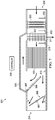
- FIGS. 3-5 illustrate another air-cooled fuel cell system freeze protection system 301 according to this disclosure.
- System 301 comprises the same elements as system 201 without the heater 203 .
- System 301 further comprises a heat exchanger 303 , a heat-exchanger duct 305 , an actuator 307 , a heat-exchanger door 309 , a heat-exchanger exhaust 311 , and a pressure transducer 313 .
- Controller 205 is electrically wired (not shown) to the actuator 307 to pivot the heat-exchanger door 309 as needed to heat and pressurize the supply air of the fuel cell 103 .
- FIG. 3 illustrates system 301 in a state where supply air is not heated. Air enters inlet 209 and passes through the heat exchanger 303 , the fuel cell 103 , and out of outlet 211 .
- the heat exchanger 303 in FIG. 3 will not raise an air temperature of the supply air because heat-exchanger door 309 is in a closed position and excess heat from the fuel cell 103 is ejected from the outlet 211 .
- FIG. 4 illustrates system 301 in a state where supply air is fully heated. Air enters inlet 209 and passes through the heat exchanger 303 , the fuel cell 103 , the heat-exchanger duct 305 , through the heat exchanger 303 a second time, and out of heat-exchanger exhaust 311 .
- the heat exchanger 303 in FIG. 4 will raise an air temperature of the supply air as much as possible because heat-exchanger door 309 is in a fully opened position and excess heat from the fuel cell 103 is thermally transmitted in the heat exchanger 303 .
- the controller 205 can detect dropping air density with the altimeter 113 . By varying temperature inside the fuel cell 103 , the controller 205 also varies air pressure inside the fuel cell 103 .
- the heat-exchanger duct 305 features an unequal and smaller cross-sectional area as compared to duct 207 , therefore, pressure inside the fuel cell 103 rises as the air is forced into the duct 305 .
- the controller 205 can measure an increase in air pressure at the fuel cell 103 via the pressure transducer 313 .
- FIG. 5 illustrates system 301 in a state where supply air is partially heated. Air enters inlet 209 and some is passed through the heat exchanger 303 , the fuel cell 103 , the heat-exchanger duct 305 , through the heat exchanger 303 a second time, and out of heat-exchanger exhaust 311 , and the rest is ejected from outlet 211 .
- the heat exchanger 303 in FIG. 5 will raise an air temperature of the supply air a selected amount because heat-exchanger door 309 is in a partially opened position and excess heat from the fuel cell 103 is thermally transmitted in the heat exchanger 303 and also ejected from the outlet 211 .
- Controller 205 selectively positions the heat-exchanger door 309 as needed to vary the temperature of fuel cell 103 .
- FIG. 6 illustrates another air-cooled fuel cell system freeze protection system 401 according to this disclosure.
- System 401 comprises the same elements as system 301 but further comprises a detachable electric heater 403 .
- Heater 403 comprises electric heating elements 405 , a heater housing 407 , and an electric fan 409 .
- Heater 403 is configured for heating the air-cooled fuel cell 103 of the rotorcraft 101 for a period of time until a heat exchanger 303 is capable of heating supply air.
- Heater 403 is inserted into the inlet 209 and powered by the aircraft, a battery, or other suitable power supply.
- the heater housing 407 is configured to generally seal the inlet 209 .
- the fan 409 draws air into the inlet 209 from opening 411 and across the heating elements 405 . Because the heater 403 is removable, once the air-cooled fuel cell 103 is sufficiently warmed for operation, then the heater 403 is removed from the rotorcraft 101 .
- FIG. 7 illustrates another air-cooled fuel cell system freeze protection system 501 according to this disclosure.
- System 501 comprises the same elements as system 301 but further comprises a heater 203 , a heater thermocouple 503 , a butterfly valve 505 , an actuator 507 , and a pressure transducer 313 .
- System 501 can correct for altitude with changes in pressure and temperature independent of each other, whereas system 301 corrected for altitude with changes in pressure and temperature concurrently.
- the combination of the heater 203 and the heat exchanger 303 enables system 501 to quickly and efficiently heat the fuel cell 103 .
- the butterfly valve 505 enables system 501 to increase a pressure of the supply air.
- the heat exchanger 303 in FIG. 7 will raise an air temperature of the supply air a selected amount because heat-exchanger door 309 is in a partially opened position and excess heat from the fuel cell 103 is thermally transmitted in the heat exchanger 303 and also ejected from the outlet 211 .
- Controller 205 selectively positions the heat-exchanger door 309 as needed to vary the temperature of fuel cell 103 . Additionally, controller 205 selectively activates heater 203 as needed to warm the fuel cell 103 . Initially, the system 501 may operate heater 203 until fuel cell 103 is warmed and then operate the heat exchanger 303 as needed to maintain the fuel cell 103 in a heated state without using the heater 203 .
- FIGS. 8-10 illustrate another air-cooled fuel cell system freeze protection system 601 according to this disclosure.
- System 601 comprises the same elements as system 301 , but further comprises a heat-exchanger duct 603 , having a cross-sectional area equal to duct 207 , instead of duct 305 .
- FIG. 8 illustrates system 601 in a state where supply air is pressurized but not heated. Air enters inlet 209 and passes through the heat exchanger 303 , the fuel cell 103 , the butterfly valve 505 , and out of outlet 211 .
- the heat exchanger 303 in FIG. 8 will not raise an air temperature of the supply air because heat-exchanger door 309 is in a closed position and excess heat from the fuel cell 103 is ejected from the outlet 211 .
- FIG. 9 illustrates system 601 in a state where supply air is fully heated but not pressurized. Air enters inlet 209 and passes through the heat exchanger 303 , the fuel cell 103 , the heat-exchanger duct 603 , through the heat exchanger 303 a second time, and out of heat-exchanger exhaust 311 .
- the heat exchanger 303 in FIG. 9 will raise an air temperature of the supply air as much as possible because heat-exchanger door 309 is in a fully opened position and excess heat from the fuel cell 103 is thermally transmitted in the heat exchanger 303 .
- the controller 205 can detect dropping air density with the altimeter 113 .
- the controller 205 also varies air pressure inside the fuel cell 103 by varying temperature inside the fuel cell 103 .
- the heat-exchanger duct 305 features an equal cross-sectional area as compared to duct 207 . Therefore, air pressure inside the fuel cell 103 does not rise as the air is forced into the duct 603 .
- FIG. 10 illustrates system 601 in a state where supply air is partially heated and pressurized. Air enters inlet 209 , and some is passed through the heat exchanger 303 , the fuel cell 103 , the heat-exchanger duct 603 , through the heat exchanger 303 a second time, and out of heat-exchanger exhaust 311 , and the rest is ejected from outlet 211 .
- the heat exchanger 303 in FIG. 10 will raise an air temperature of the supply air a selected amount because heat-exchanger door 309 is in a partially opened position and excess heat from the fuel cell 103 is thermally transmitted in the heat exchanger 303 and also ejected from the outlet 211 .
- Controller 205 selectively positions the heat-exchanger door 309 as needed to vary the temperature of fuel cell 103 .
- Controller 205 can measure an increase in air pressure at the fuel cell 103 via the pressure transducer 313 .
- the butterfly valve 505 enables the system 601 to increase a pressure of the supply air by closing the valve 505 .
- R R l +k*(R u ⁇ R l ), wherein k is a variable ranging from 1 percent to 100 percent with a 1 percent increment, i.e., k is 1 percent, 2 percent, 3 percent, 4 percent, 5 percent, . . . 50 percent, 51 percent, 52 percent, . . . , 95 percent, 96 percent, 95 percent, 98 percent, 99 percent, or 100 percent.
- any numerical range defined by two R numbers as defined in the above is also specifically disclosed.
Landscapes
- Engineering & Computer Science (AREA)
- Chemical & Material Sciences (AREA)
- Sustainable Energy (AREA)
- General Chemical & Material Sciences (AREA)
- Electrochemistry (AREA)
- Chemical Kinetics & Catalysis (AREA)
- Life Sciences & Earth Sciences (AREA)
- Manufacturing & Machinery (AREA)
- Sustainable Development (AREA)
- Combustion & Propulsion (AREA)
- Aviation & Aerospace Engineering (AREA)
- Mechanical Engineering (AREA)
- Computing Systems (AREA)
- Health & Medical Sciences (AREA)
- Artificial Intelligence (AREA)
- Automation & Control Theory (AREA)
- Evolutionary Computation (AREA)
- Fuzzy Systems (AREA)
- Medical Informatics (AREA)
- Software Systems (AREA)
- Theoretical Computer Science (AREA)
- Remote Sensing (AREA)
- Fuel Cell (AREA)
Abstract
Description
Claims (15)
Priority Applications (1)
| Application Number | Priority Date | Filing Date | Title |
|---|---|---|---|
| US16/435,546 US11152631B2 (en) | 2019-06-09 | 2019-06-09 | Air-cooled fuel-cell freeze-protection system |
Applications Claiming Priority (1)
| Application Number | Priority Date | Filing Date | Title |
|---|---|---|---|
| US16/435,546 US11152631B2 (en) | 2019-06-09 | 2019-06-09 | Air-cooled fuel-cell freeze-protection system |
Publications (2)
| Publication Number | Publication Date |
|---|---|
| US20200388865A1 US20200388865A1 (en) | 2020-12-10 |
| US11152631B2 true US11152631B2 (en) | 2021-10-19 |
Family
ID=73650805
Family Applications (1)
| Application Number | Title | Priority Date | Filing Date |
|---|---|---|---|
| US16/435,546 Active 2040-04-01 US11152631B2 (en) | 2019-06-09 | 2019-06-09 | Air-cooled fuel-cell freeze-protection system |
Country Status (1)
| Country | Link |
|---|---|
| US (1) | US11152631B2 (en) |
Families Citing this family (10)
| Publication number | Priority date | Publication date | Assignee | Title |
|---|---|---|---|---|
| US11866169B2 (en) * | 2020-08-07 | 2024-01-09 | Textron Innovations Inc. | System and method for supplying passively filtered ram air to a hydrogen fuel cell of a UAV |
| JP7456415B2 (en) * | 2021-04-23 | 2024-03-27 | トヨタ自動車株式会社 | Fuel cell system and aircraft |
| FR3128693B1 (en) | 2021-10-28 | 2023-10-20 | Airbus Helicopters | Aircraft equipped with a cooling system for an onboard fuel cell |
| US20230155242A1 (en) * | 2021-11-16 | 2023-05-18 | Beta Air, Llc | System and method for battery ventilation of an electric aircraft |
| JP7692347B2 (en) * | 2021-12-28 | 2025-06-13 | 本田技研工業株式会社 | Aircraft and method |
| US11949121B2 (en) * | 2021-12-29 | 2024-04-02 | Beta Air, Llc | Systems and methods for a venting seal for battery modules in an electric aircraft |
| CN116412055A (en) * | 2021-12-31 | 2023-07-11 | 重庆宗申航空发动机制造股份有限公司 | Auxiliary equipment for unmanned aerial vehicle engine start |
| CN116412054A (en) * | 2021-12-31 | 2023-07-11 | 重庆宗申航空发动机制造股份有限公司 | An unmanned aerial vehicle engine startup support equipment |
| US12486016B2 (en) * | 2023-04-03 | 2025-12-02 | Joby Aero, Inc. | High efficiency air intake system and aircraft using same |
| FR3153473A1 (en) * | 2023-09-21 | 2025-03-28 | Safran | METHOD FOR ADJUSTING A FUEL CELL COOLING SYSTEM |
Citations (2)
| Publication number | Priority date | Publication date | Assignee | Title |
|---|---|---|---|---|
| KR20170014295A (en) * | 2015-07-29 | 2017-02-08 | 하이리움산업(주) | Power supply system for unmanned aerial vehicle and control method of the same |
| US20170125831A1 (en) * | 2015-11-02 | 2017-05-04 | Parker-Hannifin Corporation | Fuel cell cathode switching for aircraft applications |
-
2019
- 2019-06-09 US US16/435,546 patent/US11152631B2/en active Active
Patent Citations (2)
| Publication number | Priority date | Publication date | Assignee | Title |
|---|---|---|---|---|
| KR20170014295A (en) * | 2015-07-29 | 2017-02-08 | 하이리움산업(주) | Power supply system for unmanned aerial vehicle and control method of the same |
| US20170125831A1 (en) * | 2015-11-02 | 2017-05-04 | Parker-Hannifin Corporation | Fuel cell cathode switching for aircraft applications |
Non-Patent Citations (1)
| Title |
|---|
| Machine Translation KR20170014295(A) (Year: 2017). * |
Also Published As
| Publication number | Publication date |
|---|---|
| US20200388865A1 (en) | 2020-12-10 |
Similar Documents
| Publication | Publication Date | Title |
|---|---|---|
| US11152631B2 (en) | Air-cooled fuel-cell freeze-protection system | |
| US11749851B2 (en) | Thermal regulation of batteries | |
| US20250051019A1 (en) | Aerospace fuel cell system integration | |
| JP5084720B2 (en) | System and method for cargo compartment air conditioning using recirculated air | |
| US9656756B2 (en) | Turbo-compressor system and method for extracting energy from an aircraft engine | |
| EP3543131B1 (en) | Cooling system, air conditioning pack, and method for conditioning air | |
| EP2651763B1 (en) | Method and device for controlling an aircraft air conditioning system | |
| US8522572B2 (en) | Adaptive power and thermal management system | |
| Swider-Lyons et al. | Hydrogen fule cell propulsion for long endurance small UVAs | |
| US11942611B2 (en) | Thermal regulation of batteries | |
| EP2452056B1 (en) | Thermal conditioning for air separation modules | |
| US8209066B2 (en) | Environmental control system for precision airborne payloads | |
| US10816019B2 (en) | Hydraulic fluid warming system and method | |
| EP4279387B1 (en) | Hydrogen-cooled environmental control system | |
| CN103958347A (en) | System and method for cooling an aircraft wing | |
| US11721857B2 (en) | Thermal regulation of batteries | |
| EP3122636B1 (en) | System and method for providing temperature control | |
| Bradley et al. | Test results for a fuel cell-powered demonstration aircraft | |
| US2929224A (en) | Gas turbine compressor driven air conditioning system | |
| EP1282556B1 (en) | In flight entertainment (ife) cabinet cooling system | |
| US20210380273A1 (en) | Portable aircraft shelter | |
| WO2014030024A1 (en) | Pre-cooler system with bypass valve, controller therefor, method and aircraft using the same | |
| EP3753851A2 (en) | Thermal regulation of batteries | |
| Gavrilovic et al. | Flight Testing of a Hydrogen Powered Unmanned Aerial System | |
| US20250319971A1 (en) | Stratospheric balloon capsule temperature & humidity control system |
Legal Events
| Date | Code | Title | Description |
|---|---|---|---|
| FEPP | Fee payment procedure |
Free format text: ENTITY STATUS SET TO UNDISCOUNTED (ORIGINAL EVENT CODE: BIG.); ENTITY STATUS OF PATENT OWNER: LARGE ENTITY |
|
| AS | Assignment |
Owner name: BELL HELICOPTER TEXTRON INC., TEXAS Free format text: ASSIGNMENT OF ASSIGNORS INTEREST;ASSIGNOR:RAINVILLE, JOSEPH D.;REEL/FRAME:049417/0219 Effective date: 20190530 |
|
| STPP | Information on status: patent application and granting procedure in general |
Free format text: NOTICE OF ALLOWANCE MAILED -- APPLICATION RECEIVED IN OFFICE OF PUBLICATIONS |
|
| AS | Assignment |
Owner name: BELL TEXTRON INC., TEXAS Free format text: CHANGE OF NAME;ASSIGNOR:BELL HELICOPTER TEXTRON INC.;REEL/FRAME:056494/0076 Effective date: 20191015 |
|
| STPP | Information on status: patent application and granting procedure in general |
Free format text: PUBLICATIONS -- ISSUE FEE PAYMENT RECEIVED |
|
| STPP | Information on status: patent application and granting procedure in general |
Free format text: PUBLICATIONS -- ISSUE FEE PAYMENT VERIFIED |
|
| AS | Assignment |
Owner name: BELL HELICOPTER RHODE ISLAND, RHODE ISLAND Free format text: ASSIGNMENT OF ASSIGNORS INTEREST;ASSIGNOR:BELL TEXTRON INC.;REEL/FRAME:056532/0664 Effective date: 20200101 Owner name: TEXTRON INNOVATIONS INC., RHODE ISLAND Free format text: ASSIGNMENT OF ASSIGNORS INTEREST;ASSIGNOR:BELL HELICOPTER RHODE ISLAND;REEL/FRAME:056532/0740 Effective date: 20200101 |
|
| STCF | Information on status: patent grant |
Free format text: PATENTED CASE |
|
| MAFP | Maintenance fee payment |
Free format text: PAYMENT OF MAINTENANCE FEE, 4TH YEAR, LARGE ENTITY (ORIGINAL EVENT CODE: M1551); ENTITY STATUS OF PATENT OWNER: LARGE ENTITY Year of fee payment: 4 |