US11150463B2 - Optical module and electronic apparatus - Google Patents
Optical module and electronic apparatus Download PDFInfo
- Publication number
- US11150463B2 US11150463B2 US16/047,069 US201816047069A US11150463B2 US 11150463 B2 US11150463 B2 US 11150463B2 US 201816047069 A US201816047069 A US 201816047069A US 11150463 B2 US11150463 B2 US 11150463B2
- Authority
- US
- United States
- Prior art keywords
- fixing member
- base
- filter
- optical module
- interference filter
- Prior art date
- Legal status (The legal status is an assumption and is not a legal conclusion. Google has not performed a legal analysis and makes no representation as to the accuracy of the status listed.)
- Active, expires
Links
- 230000003287 optical effect Effects 0.000 title claims abstract description 51
- 239000000758 substrate Substances 0.000 claims description 91
- NJPPVKZQTLUDBO-UHFFFAOYSA-N novaluron Chemical compound C1=C(Cl)C(OC(F)(F)C(OC(F)(F)F)F)=CC=C1NC(=O)NC(=O)C1=C(F)C=CC=C1F NJPPVKZQTLUDBO-UHFFFAOYSA-N 0.000 claims description 14
- 238000005259 measurement Methods 0.000 description 32
- 230000008859 change Effects 0.000 description 29
- 230000001133 acceleration Effects 0.000 description 21
- 230000005540 biological transmission Effects 0.000 description 16
- 238000013016 damping Methods 0.000 description 14
- 238000012545 processing Methods 0.000 description 12
- 230000000052 comparative effect Effects 0.000 description 8
- 239000010408 film Substances 0.000 description 5
- 230000035515 penetration Effects 0.000 description 5
- 238000012937 correction Methods 0.000 description 4
- 238000001514 detection method Methods 0.000 description 4
- 238000005286 illumination Methods 0.000 description 4
- 238000006073 displacement reaction Methods 0.000 description 3
- 239000000463 material Substances 0.000 description 3
- 239000002184 metal Substances 0.000 description 3
- 230000004308 accommodation Effects 0.000 description 2
- 238000010586 diagram Methods 0.000 description 2
- 239000011521 glass Substances 0.000 description 2
- 238000007689 inspection Methods 0.000 description 2
- 238000000034 method Methods 0.000 description 2
- 238000012986 modification Methods 0.000 description 2
- 230000004048 modification Effects 0.000 description 2
- 238000013459 approach Methods 0.000 description 1
- 230000008901 benefit Effects 0.000 description 1
- 239000000919 ceramic Substances 0.000 description 1
- 230000000694 effects Effects 0.000 description 1
- 230000005284 excitation Effects 0.000 description 1
- 230000006870 function Effects 0.000 description 1
- 230000006872 improvement Effects 0.000 description 1
- 230000007246 mechanism Effects 0.000 description 1
- 230000000149 penetrating effect Effects 0.000 description 1
- 229920005989 resin Polymers 0.000 description 1
- 239000011347 resin Substances 0.000 description 1
- 230000000452 restraining effect Effects 0.000 description 1
- 229920002050 silicone resin Polymers 0.000 description 1
- 239000010409 thin film Substances 0.000 description 1
Images


Classifications
-
- G—PHYSICS
- G01—MEASURING; TESTING
- G01J—MEASUREMENT OF INTENSITY, VELOCITY, SPECTRAL CONTENT, POLARISATION, PHASE OR PULSE CHARACTERISTICS OF INFRARED, VISIBLE OR ULTRAVIOLET LIGHT; COLORIMETRY; RADIATION PYROMETRY
- G01J3/00—Spectrometry; Spectrophotometry; Monochromators; Measuring colours
- G01J3/02—Details
- G01J3/0202—Mechanical elements; Supports for optical elements
-
- B—PERFORMING OPERATIONS; TRANSPORTING
- B41—PRINTING; LINING MACHINES; TYPEWRITERS; STAMPS
- B41J—TYPEWRITERS; SELECTIVE PRINTING MECHANISMS, i.e. MECHANISMS PRINTING OTHERWISE THAN FROM A FORME; CORRECTION OF TYPOGRAPHICAL ERRORS
- B41J2/00—Typewriters or selective printing mechanisms characterised by the printing or marking process for which they are designed
- B41J2/005—Typewriters or selective printing mechanisms characterised by the printing or marking process for which they are designed characterised by bringing liquid or particles selectively into contact with a printing material
- B41J2/01—Ink jet
-
- G—PHYSICS
- G01—MEASURING; TESTING
- G01J—MEASUREMENT OF INTENSITY, VELOCITY, SPECTRAL CONTENT, POLARISATION, PHASE OR PULSE CHARACTERISTICS OF INFRARED, VISIBLE OR ULTRAVIOLET LIGHT; COLORIMETRY; RADIATION PYROMETRY
- G01J3/00—Spectrometry; Spectrophotometry; Monochromators; Measuring colours
- G01J3/02—Details
- G01J3/0205—Optical elements not provided otherwise, e.g. optical manifolds, diffusers, windows
- G01J3/0229—Optical elements not provided otherwise, e.g. optical manifolds, diffusers, windows using masks, aperture plates, spatial light modulators or spatial filters, e.g. reflective filters
-
- G—PHYSICS
- G01—MEASURING; TESTING
- G01J—MEASUREMENT OF INTENSITY, VELOCITY, SPECTRAL CONTENT, POLARISATION, PHASE OR PULSE CHARACTERISTICS OF INFRARED, VISIBLE OR ULTRAVIOLET LIGHT; COLORIMETRY; RADIATION PYROMETRY
- G01J3/00—Spectrometry; Spectrophotometry; Monochromators; Measuring colours
- G01J3/12—Generating the spectrum; Monochromators
- G01J3/26—Generating the spectrum; Monochromators using multiple reflection, e.g. Fabry-Perot interferometer, variable interference filters
-
- G—PHYSICS
- G01—MEASURING; TESTING
- G01J—MEASUREMENT OF INTENSITY, VELOCITY, SPECTRAL CONTENT, POLARISATION, PHASE OR PULSE CHARACTERISTICS OF INFRARED, VISIBLE OR ULTRAVIOLET LIGHT; COLORIMETRY; RADIATION PYROMETRY
- G01J3/00—Spectrometry; Spectrophotometry; Monochromators; Measuring colours
- G01J3/46—Measurement of colour; Colour measuring devices, e.g. colorimeters
- G01J3/50—Measurement of colour; Colour measuring devices, e.g. colorimeters using electric radiation detectors
- G01J3/501—Colorimeters using spectrally-selective light sources, e.g. LEDs
-
- G—PHYSICS
- G02—OPTICS
- G02B—OPTICAL ELEMENTS, SYSTEMS OR APPARATUS
- G02B26/00—Optical devices or arrangements for the control of light using movable or deformable optical elements
- G02B26/001—Optical devices or arrangements for the control of light using movable or deformable optical elements based on interference in an adjustable optical cavity
Definitions
- the present invention relates to an optical module and an electronic apparatus.
- an interference filter having a pair of mirrors arranged facing each other is known.
- an optical filter device having an interference filter accommodated in a sealed space of a package casing is known (see, for example, JP-A-2015-227970).
- the interference filter is fixed to a part of the casing via a damping member.
- the damping member restrains vibrations of the interference filter when the interference filter vibrates. Therefore, for example, even if the interference filter vibrates when driven, flexure of the mirrors of the interference filter due to the vibrations can be restrained.
- the casing (package casing) of the optical filter device as described above is fixed to a predetermined base of an electronic apparatus, disturbance vibrations may be transmitted to the package casing from the base.
- the influence of vibrations of the interference filter itself can be restrained but the influence of such disturbance vibrations is difficult to eliminate.
- the disturbance vibrations transmitted to the interference filter from the base via the package casing cause the interference filter to vibrate. In this case, the wavelength of light outputted from the interference filter changes, generating the problem of being unable to output light of a desired wavelength with high accuracy.
- An advantage of some aspects of the invention is that an optical module which can output light of a predetermined wavelength with high accuracy and an electronic apparatus are provided.
- An optical module includes: a filter holding member to which an interference filter having a pair of mirrors facing each other is fixed; a base to which the filter holding member is fixed; and a first fixing member which fixes the filter holding member to the base.
- k ⁇ m ⁇ 2 /2 is satisfied, where k is a spring constant of the first fixing member, ⁇ is a frequency of vibration generated in the base, and m is a total mass of the interference filter and the filter holding member.
- the spring constant k of the first fixing member satisfies the condition of k ⁇ m ⁇ 2 /2.
- the rate of transmission of vibrations from the base to the casing is less than 1.0. This reduces vibrations from the base to the filter holding member and also restrains vibrations of the interference filter.
- changes in the wavelength of light transmitted through the interference filter can be restrained, making it possible for the interference filter to transmit light of a desired wavelength with high accuracy.
- the spring constant of the first fixing member satisfies k ⁇ m ⁇ 2 /12.25.
- the rate of transmission of vibrations from the base to the casing can be reduced to 0.5 or lower, regardless of the damping coefficient of the first fixing member. This can restrain vibrations from the base to the filter holding member more effectively.
- the interference filter is fixed to the filter holding member via a second fixing member, and that the second fixing member has a spring constant greater than the spring constant of the first fixing member.
- an elastic member to damp vibrations is normally used as the second fixing member in order to reduce the influence of vibrations of the interference filter itself.
- the first fixing member has a spring constant satisfying k ⁇ m ⁇ 2 /2, as described above. If the interference filter is fixed to the filter holding member via the second fixing member having a smaller spring constant, the attitude of the interference filter cannot be maintained. For example, if the interference filter is fixed at one position to the filter holding member (casing) as described in JP-A-2015-227970, the interference filter tilts about the second fixing member (connecting position to the filter holding member).
- the second fixing member having a greater spring constant than the first fixing member can properly fix the interference filter to the filter holding member while restraining the tilt and flexure of the interference filter, and can also restrain vibrations of the interference filter itself.
- the optical module according to the application example includes a light receiving unit which receives light transmitted through the interference filter, and a third fixing member which fixes the light receiving unit to the base, and that the third fixing member has a spring constant greater than the spring constant of the first fixing member.
- the optical module has the light receiving unit receiving light through the interference filter.
- the light receiving unit is fixed to the base via the third fixing member having a greater spring constant than the first fixing member.
- An electronic apparatus includes: an optical module as described above; and a control unit which controls the optical module.
- FIG. 1 is an external view showing a schematic configuration of a printer according to an embodiment of the invention.
- FIG. 2 is a block diagram showing a schematic configuration of the printer according to the embodiment.
- FIG. 3 is a cross-sectional view showing a schematic configuration of a spectroscope according to the embodiment.
- FIG. 4 is a cross-sectional view showing a schematic configuration of a spectroscopic device according to the embodiment.
- FIG. 5 shows a schematic configuration of a filter holding substrate according to the embodiment.
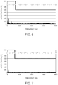
- FIG. 6 shows the frequency of vibration in an X direction of a carriage according to the embodiment and the magnitude thereof (acceleration) when the carriage is driven.
- FIG. 7 shows the frequency of vibration in a Y direction of the carriage according to the embodiment and the magnitude thereof (acceleration) when the carriage is driven.
- FIG. 8 shows the frequency of vibration in a Z direction of the carriage according to the embodiment and the magnitude thereof (acceleration) when the carriage is driven.
- FIG. 9 shows the frequency of vibration transmitted to a variable-wavelength interference filter and the amount of change of a mirror gap due to the vibration.
- FIG. 10 shows the acceleration of vibration of the carriage allowed when the amount of change of the mirror gap is less than an allowable value.
- FIG. 11 shows the rate of transmission of vibrations from a base to the filter holding substrate.
- printer inkjet printer
- optical module optical module
- FIG. 1 is a perspective view showing an example of the external configuration of the printer 1 according to the embodiment.
- FIG. 2 is a block diagram showing a schematic configuration of the printer 1 according to the embodiment.
- the printer 1 is equivalent to the electronic apparatus according to the invention and includes a unit casing 10 , a supply unit 11 , a carrying unit 12 , a carriage 13 , a carriage moving unit 14 , and a control unit 15 (see FIG. 2 ) equivalent to the control unit according to the invention.
- the carriage 13 is provided with a print unit 16 and a spectroscope 17 , as shown in FIG. 2 .
- the printer 1 controls the units 11 , 12 , 14 and the carriage 13 , based on print data inputted from an external apparatus 20 such as a personal computer, and prints an image on a medium M.
- the printer 1 in this embodiment also forms a color patch (pattern image) for color measurement at a predetermined position on the medium M, based on preset calibration print data, and carries out spectroscopic measurement on the color patch.
- the printer 1 compares a measured value on the color patch with the calibration print data and carries out various kinds of correction processing when printing.
- the supply unit 11 is a unit which supplies the medium M to be an image forming target, to an image forming position.
- the supply unit 11 has, for example, a roll body 111 with the medium M wound thereon, a roll drive motor (not illustrated), and a roll drive wheel train (not illustrated) or the like. Based on a command from the control unit 15 , the roll drive motor is rotationally driven. The rotating force of the roll drive motor is transmitted to the roll body 111 via the roll drive wheel train. This causes the roll body 111 to rotate, supplying a sheet of paper wound on the roll body 111 downstream in a Y direction (sub scanning direction), that is, in a +Y direction.
- the medium M may be supplied by any supply method.
- the medium M in the form of sheets of paper stacked on a tray or the like may be supplied, for example, one by one, by a roller or the like.
- the carrying unit 12 carries the medium M supplied from the supply unit 11 , along the Y direction.
- the carrying unit 12 has a carrying roller 121 , a driven roller (not illustrated) arranged so as to interpose the medium between the carrying roller 121 and the driven roller and following the carrying roller 121 , and a platen 122 .
- the driving force from a carrying motor, not illustrated, is transmitted to the carrying roller 121 .
- the carrying roller 121 is rotationally driven by the rotational force and carries the medium M along the Y direction, with the medium M held between the carrying roller 121 and the driven roller.
- the platen 122 facing the carriage 13 is provided downstream of the carrying roller 121 in the Y direction, that is, on the +Y side.
- the carriage 13 has the print unit 16 , which prints an image on the medium M, and the spectroscope 17 , which carries out spectroscopic measurement at a predetermined measurement position P (see FIG. 3 ) on the medium M.
- the carriage 13 is provided in such a way as to be movable by the carriage moving unit 14 along a main scanning direction (X direction) intersecting the Y direction.
- the carriage 13 is connected to the control unit 15 by a flexible circuit 131 and carries out print processing by the print unit 16 and spectroscopic measurement processing by the spectroscope 17 , based on a command from the control unit 15 .
- the carriage moving unit 14 forms a moving mechanism according to the invention and moves the carriage 13 to reciprocate along the X direction, based on a command from the control unit 15 .
- the carriage moving unit 14 includes, for example, a carriage guide shaft 141 , a carriage motor 142 , and a timing belt 143 .
- the carriage guide shaft 141 is arranged along the X direction and has its both ends fixed to, for example, the casing of the printer 1 .
- the carriage motor 142 drives the timing belt 143 .
- the timing belt 143 is supported substantially parallel to the carriage guide shaft 141 and has a part of the carriage 13 fixed thereto.
- the carriage motor 142 is driven based on a command from the control unit 15 , the timing belt 143 is made to travel forward and backward. This causes the carriage 13 fixed to the timing belt 143 to reciprocate, guided by the carriage guide shaft 141 .
- the control unit 15 includes an I/F 151 , a unit control circuit 152 , a memory 153 , and a CPU (central processing unit) 154 , as shown in FIG. 2 .
- the I/F 151 input print data inputted from the external apparatus 20 , to the CPU 154 .
- the unit control circuit 152 has a control circuit which controls each of the supply unit 11 , the carrying unit 12 , the carriage moving unit 14 , the print unit 16 , and the spectroscope 17 .
- the unit control circuit 152 controls the operation of each unit, based on a command signal from the CPU 154 .
- the control circuit for each unit may be provided separately from the control unit 15 and connected to the control unit 15 .
- the memory 153 stores various programs and various data to control the operation of the printer 1 .
- the various data may be, for example, print profile data which stores the amount of each ink ejected corresponding to color data included as print data, and drive table data to drive a spectroscopic device 600 .
- the memory 153 may also store light emitting characteristics to each wavelength of a light source 176 , described later, and spectroscopic characteristic of the spectroscopic device 600 , or the like.
- the CPU 154 reads out and executes the various programs stored in the memory 153 and thus carries out drive control on the supply unit 11 , the carrying unit 12 , and the carriage moving unit 14 , print control on the print unit 16 , spectroscopic measurement control on the spectroscope 17 , and correction processing (for example, correction of uneven density, correction of color shift) or the like based on the result of spectroscopic measurement).
- the print unit 16 carries out print processing at a part facing the medium M, in which the print unit 16 ejects individual droplets of ink on the medium M and thus forms an image on the medium M, based on a command signal from the control unit 15 (image forming processing on the medium M).
- FIG. 3 is a cross-sectional view showing a schematic configuration of the spectroscope 17 .
- the spectroscope 17 forms the optical module according to the invention and has a base 171 , a filter holding substrate 172 held (fixed) on the base 171 , a light receiving element holding substrate 173 fixed to the base 171 , and a cover section 174 , as shown in FIG. 3 .
- the base 171 is brought into contact with the carriage 13 and fixed there, for example, with a screw or the like.
- the base 171 has a first base section 171 A and a second base section 171 B.
- the first base section 171 A has a measurement light introducing section 175 through which light reflected at a measurement position P on the medium M passes, and a light source arrangement section 177 where a light source 176 is arranged.
- the measurement light introducing section 175 is a penetration hole, for example, along a Z direction, and has a window section 175 A at an end part on the +Z side.
- an optical holding section 178 which holds an incident optical system including, for example, an aperture 178 A and an incident lens 178 B, is fixed.
- the optical axis (measurement optical axis L) of the window section 175 A, the aperture 178 A, and the incident lens 178 B coincides with the optical axis of the spectroscopic device 600 (variable-wavelength interference filter 5 ) and a light receiving element 173 A (light receiving unit), described later.
- the light source arrangement section 177 has, for example, a cylindrical hole section 177 A whose center axis approaches the measurement optical axis L as it goes toward the +Z side. On the ⁇ Z side of the cylindrical hole section 177 A, the light source 176 is fixed.
- the light source 176 can be, for example, an LED.
- An LED substrate provided with the LED is fixed to an end part on the ⁇ Z side of the cylindrical hole section 177 A, for example, with a screw, thus fixing the LED (light source 176 ) on the base 171 .
- the substrate (LED substrate or the like) holding the light source 176 is connected to a connector 174 B, described later.
- An end part on the +Z side of the cylindrical hole section 177 A is an illumination window 177 B through which the light of the light source 176 is emitted.
- the illumination window 177 B faces the medium M placed on the platen 122 .
- illumination light is cast at the measurement position P within a predetermined range around the point of intersection between the medium M and the measurement optical axis L.
- spectroscopic measurement is carried out according to a method under an optical geometry condition (45° x: 0°) prescribed by the color measurement standard (JIS Z8722).
- the illumination light from the light source 176 is made incident at an angle of incidence of 45° ⁇ 2° to the measurement position P, and the light reflected by a measurement target into a normal direction with 0° ⁇ 10° becomes incident on the light receiving element 173 A along the measurement optical axis L.
- the second base section 171 B is fixed to the first base section 171 A, for example, with a screw or the like.
- the filter holding substrate 172 and the light receiving element holding substrate 173 are fixed to the second base section 171 B.
- the filter holding substrate 172 is fixed to the base 171 via a first fixing member 181 . Details of the first fixing member 181 will be described later.
- the spectroscopic device 600 is fixed on the filter holding substrate 172 .
- the spectroscopic device 600 is brought into contact with the filter holding substrate 172 and fixed there with a screw or the like.
- the filter holding substrate 172 and a casing 610 of the spectroscopic device 600 are separate bodies firmly fixed to each other with a screw.
- this example is not limiting.
- the filter holding substrate 172 and the casing 610 of the spectroscopic device 600 may be integrated together.
- FIG. 4 is a cross-sectional view showing a schematic configuration of the spectroscopic device 600 .
- the spectroscopic device 600 has the casing 610 and a variable-wavelength interference filter (the interference filter according to the invention) accommodated inside the casing 610 .
- the casing 610 and the filter holding substrate 172 on which the casing 610 is fixed form the filter holding member according to the invention.
- the casing 610 has a base 620 and a lid 630 , as shown in FIG. 4 .
- the base 620 and the lid 630 are joined together, thus forming an accommodation space therein.
- the variable-wavelength interference filter 5 is accommodated inside the accommodation space.
- the variable-wavelength interference filter 5 has a first substrate 51 and a second substrate 52 facing the first substrate 51 .
- a first mirror 54 is provided on the surface facing the second substrate 52 of the first substrate 51 .
- a second mirror 55 facing the first mirror 54 is provided. That is, the first mirror 54 and the second mirror 55 are equivalent to the pair of mirrors according to the invention and are arranged facing each other via a mirror gap G.
- the first mirror 54 and the second mirror 55 are made up of, for example, a metal film or a dielectric multilayer film.
- electrically conductive films for example, an ITO film and a metal thin film of Ag or the like. This enables the first mirror 54 and the second mirror 55 to be electrically conductive and also function as a capacitance detection unit.
- the second substrate 52 is provided with a movable section 521 on which the second mirror 55 is provided, and a diaphragm section 522 provided on the outer circumference of the movable section 521 and having a smaller thickness than the movable section 521 .
- the first substrate 51 has a first electrode 561 on the surface facing the second substrate 52 .
- the second substrate 52 has a second electrode 562 facing the first electrode 561 .
- the first electrode 561 and the second electrode 562 form an electrostatic actuator 56 . Applying a voltage between the first electrode 561 and the second electrode 562 causes the diaphragm section 522 of the second substrate 52 to flex and causes the movable section 521 to be displaced toward the first substrate 51 .
- the dimension of the mirror gap G thus changes. This enables the variable-wavelength interference filter 5 to transmit light with a wavelength corresponding to the mirror gap dimension.
- variable-wavelength interference filter 5 in this embodiment, one end part of the first substrate 51 forms a filter fixing end 511 protruding further outward than one end part of the second substrate 52 .
- the filter fixing end 511 is fixed to the casing 610 via a second fixing member 64 .
- the other end part opposite to the one end part of the second substrate 52 protrudes further outward than the other end part of the first substrate 51 and forms an electrical equipment section 563 .
- a wire 563 A connected independently to each of the first mirror 54 , the second mirror 55 , the first electrode 561 , and the second electrode 562 is arranged and connected to a terminal (internal terminal section 624 ) provided in the casing 610 .
- the casing 610 is made up of the base 620 and the lid 630 , as described above.
- the base 620 is made up of, for example, ceramics, and has a pedestal section 621 and a sidewall section 622 .
- the pedestal section 621 is forms in the shape of a flat plate having, for example, a rectangular outer shape as viewed in a plan view of the filter.
- the sidewall section 622 in a cylindrical shape rises toward the lid 630 from an outer circumferential part of the pedestal section 621 .
- the pedestal section 621 has an opening 623 penetrating the pedestal section 621 in a direction of thickness along the optical axis (measurement optical axis L) of the light receiving element 173 A.
- the opening 623 is provided in such a way as to include an area overlapping the first mirror 54 and the second mirror 55 as viewed in a plan view of the pedestal section 621 seen from the direction of thickness, in the state where the variable-wavelength interference filter 5 is accommodated in the casing 610 .
- a glass member 627 covering the opening 623 is joined.
- the internal terminal section 624 connected to the wire 563 A provided on the electrical equipment section 563 of the variable-wavelength interference filter 5 is provided.
- the internal terminal section 624 and the wire 563 A of the electrical equipment section 563 can be connected together, for example, by wire bonding using an Au wire or the like, or by FPC (flexible printed circuits) or the like.
- the pedestal section 621 also has a penetration hole 625 at the position where the internal terminal section 624 is provided.
- the internal terminal section 624 is connected to an external terminal section 626 provided on the base outer surface 621 B of the pedestal section 621 via the penetration hole 625 .
- the first mirror 54 , the second mirror 55 , the first electrode 561 , and the second electrode 562 of the variable-wavelength interference filter 5 are connected from the electrical equipment section 563 to a filter control section 172 A (see FIG. 5 ) via the internal terminal section 624 and the external terminal section 626 .
- the sidewall section 622 rises from an edge part of the pedestal section 621 .
- An end surface of the sidewall section 622 provided around the peripheries of the base inner surface 621 A is, for example, a flat surface parallel to the base inner surface 621 A and has the lid 630 joined thereto.
- the lid 630 is, for example, a transparent member having a rectangular outer shape as viewed in a plan view and is made up of, for example, glass or the like.
- the filter fixing end 511 of the variable-wavelength interference filter 5 is fixed to, for example, the sidewall section 622 of the base 620 via the second fixing member 64 .
- variable-wavelength interference filter 5 is fixed to the sidewall section 622 in this embodiment, this is not limiting.
- the variable-wavelength interference filter 5 may be fixed to the pedestal section 621 .
- the second fixing member 64 may be provided at a plurality of positions. However, it is preferable that the variable-wavelength interference filter 5 is fixed at one position in order to restrain transmission of the stress of the second fixing member 64 to the variable-wavelength interference filter 5 .
- a material having a greater spring constant than the first fixing member 181 is used.
- the spring constant of the second fixing member 64 is 0.1 N/mm or greater and 5.0 N/mm or smaller. If the spring constant of the second fixing member 64 is smaller than 0.1 N/mm, the strength of fixture of the variable-wavelength interference filter 5 is insufficient, making it difficult to maintain the attitude of the variable-wavelength interference filter 5 . For example, if the variable-wavelength interference filter 5 is fixed to the sidewall section 622 , as shown in FIG. 4 , the variable-wavelength interference filter 5 may tilt about the filter fixing end 511 (second fixing member 64 ).
- variable-wavelength interference filter 5 may vibrate when driven. This may cause the first mirror 54 and the second mirror 55 to flex or may cause the second mirror 55 to tilt in relation to the first mirror 54 . Meanwhile, with the spring constant within the above range, the attitude of the variable-wavelength interference filter 5 can be maintained at a predetermined position. Also, even if the movable section 521 and the diaphragm section 522 vibrate when the electrostatic actuator 56 is driven, the inconvenience of the variable-wavelength interference filter 5 resonating due to the vibration can be restrained.
- the filter holding substrate 172 has a penetration hole facing the opening 623 of the spectroscopic device 600 and along the measurement optical axis L. Through the penetration hole, the light transmitted through the spectroscopic device 600 passes toward the light receiving element 173 A.
- the filter holding substrate 172 is also provided with various circuits which control the variable-wavelength interference filter 5 .
- the circuits are connected to a connector 175 B.
- FIG. 5 shows the configuration of the filter holding substrate 172 .
- the filter holding substrate 172 is provided with the filter control section 172 A controlling the variable-wavelength interference filter 5 .
- the filter control section 172 A includes a gap detection unit 172 B, a feedback control unit 172 C, and a microcomputer 172 D.
- the gap detection unit 172 B is connected to the first mirror 54 and the second mirror 55 and detects the electrostatic capacitance between the first mirror 54 and the second mirror 55 .
- the feedback control unit 172 C controls the drive voltage applied to the electrostatic actuator 56 , based on a command value inputted from the microcomputer 172 D. Specifically, the feedback control unit 172 C controls the drive voltage applied to the electrostatic actuator 56 , based on the electrostatic capacitance detected by the gap detection unit 172 B and the electrostatic capacitance corresponding to a target wavelength inputted from the microcomputer 172 D. This changes the mirror gap G to the dimension corresponding to the target wavelength.
- the microcomputer 172 D has a storage unit such as a memory and stores drive data to control the electrostatic actuator 56 (for example, V- ⁇ data recording the drive voltage corresponding to a measurement wavelength transmitted through the variable-wavelength interference filter 5 , and C- ⁇ data recording the electrostatic capacitance corresponding to the measurement wavelength, and the like).
- the microcomputer 172 D outputs a drive voltage and a target electrostatic capacitance corresponding to a target measurement wavelength to the feedback control unit 172 C based on the command from the control unit 15 .
- the light receiving element holding substrate 173 is fixed to the base 171 via a third fixing member 183 .
- the third fixing member 183 is a non-elastic member and is made up of, for example, a metal or resin screw or the like. That is, the light receiving element holding substrate 173 is brought into contact with and is firmly fixed to the base 171 with a screw or the like.
- the light receiving element holding substrate 173 is a substrate with the light receiving element 173 A held thereon and is fixed to the base 171 at a position on the ⁇ Z side of the filter holding substrate 172 and where the optical axis of the light receiving element 173 A coincides with the measurement optical axis L.
- the light receiving element holding substrate 173 also has various circuits which control the light receiving element 173 A. The circuits are connected to the connector 174 B.
- the cover section 174 is fixed, for example, to an outer circumferential edge of the base 171 and forms, with the base 171 , a closed space (dark space) to accommodate the filter holding substrate 172 , the light receiving element holding substrate 173 , and the optical holding section 178 , as shown in FIG. 3 .
- an opening 174 A is provided, in which the connector 174 B is provided.
- the connector 174 B is electrically connected to the control unit 15 and transmits a control signal from the control unit 15 to the light source 176 , the filter holding substrate 172 , and the light receiving element holding substrate 173 .
- the first fixing member 181 fixes the filter holding substrate 172 to the second base section 171 B and restrains the transmission of vibrations from the base 171 to the filter holding substrate 172 .
- the first fixing member 181 is provided, for example, at a plurality positions on the filter holding substrate 172 .
- the filter holding substrate 172 is formed in a rectangular shape as viewed in a plan view from the Z direction, and the first fixing member 181 is arranged in each of the four corners of the filter holding substrate 172 .
- FIG. 6 shows the frequency of vibration ⁇ in the X direction of the carriage 13 and the magnitude there of (acceleration) when the carriage 13 is driven.
- FIG. 7 shows the frequency of vibration ⁇ the Y direction of the carriage 13 and the magnitude thereof (acceleration) when the carriage 13 is driven.
- FIG. 8 shows the frequency of vibration w in the Z direction of the carriage 13 and the magnitude thereof (acceleration) when the carriage 13 is driven.
- the carriage 13 can move normally and has no influence on the print unit 16 .
- normal print processing can be carried out.
- the carriage 13 is standardized in such a way as that the acceleration is lower than 0.1 G in each direction for vibrations with a frequency lower than 250 Hz and that the acceleration is lower than 0.05 G in the X direction and the Y direction and lower than 0.01 G in the Z direction for vibrations with a frequency of 250 Hz or higher.
- the spectroscopic measurement processing by the spectroscope 17 in which the mirror gap G of the variable-wavelength interference filter 5 needs to be controlled in the order of nanometers, is more affected by vibrations than the print processing by the print unit 16 .
- vibrations with relatively high acceleration occur at 100 Hz to 250 Hz.
- the vibrations may change the mirror gap G of the variable-wavelength interference filter 5 and may affect wavelength accuracy.
- the wavelength of light transmitted through the variable-wavelength interference filter 5 changes as the movable section 521 vibrates. Therefore, the vibration of the movable section 521 , that is, the change of the mirror gap G needs to be restrained in order to maintain the light transmitted through the variable-wavelength interference filter 5 to a constant wavelength and thus maintain wavelength accuracy.
- FIG. 9 shows the frequency of vibration transmitted to the variable-wavelength interference filter 5 and the amount of change of the mirror gap G due to the vibration.
- a solid line shows the amount of change of the mirror gap G when the first fixing member 181 in the embodiment is used.
- a dashed line shows the amount of change of the mirror gap G when the filter holding substrate 172 is brought into contact with and fixed to the base 171 with a screw, instead of using the first fixing member 181 .
- a dotted-dashed line shows the amount of change of the mirror gap G when an anti-vibration rubber is used instead of the first fixing member 181 .
- variable-wavelength interference filter 5 To maintain the wavelength accuracy of variable-wavelength interference filter 5 , the amount of change of the mirror gap G due to the transmission of vibrations needs to be restrained to less than an allowable value Q 1 (in this embodiment, Q 1 ⁇ 6 nm).
- FIG. 10 shows the acceleration of vibrations of the carriage 13 allowed when the amount of change of the mirror gap G is less than the allowable value Q 1 .
- variable-wavelength interference filter 5 has a natural frequency of 400 Hz to approximately 1000 Hz, though it depends on the shape and material thereof. If vibrations with a frequency similar to the natural frequency are applied, the variable-wavelength interference filter 5 resonates, increasing the amount of change of the mirror gap G. In the example shown in FIG. 10 , the natural frequency of the variable-wavelength interference filter 5 is near 450 Hz. Therefore, the allowed acceleration is smaller for a frequency similar to the natural frequency. In this case, as shown in FIG.
- the allowable acceleration corresponding to the allowable value Q 1 of the amount of change of the mirror gap G may be smaller than the value (0.01 G) prescribed for the carriage 13 .
- the wavelength accuracy may be reduced by the vibrations of the carriage 13 .
- the allowable acceleration needs to be equal to or greater than a prescribed acceleration set for the spectroscope.
- the first fixing member 181 is provided in order to restrain the transmission of vibrations of the carriage 13 (base 171 ) to the spectroscopic device 600 via the filter holding substrate 172 .
- the first fixing member 181 is made up of a material having a smaller spring constant k than the second fixing member 64 and the third fixing member 183 .
- the spring constant k of the first fixing member 181 will now be described.
- the letter w is the angular frequency of vibrations that can occur in the base 171 .
- the transmission rate T R of vibrations (displacement) transmitted from the base 171 to the filter holding substrate 172 is found by the following formula (2):
- FIG. 11 shows the transmission rate T R of vibrations from the base 171 (second base section 171 B) to the filter holding substrate 172 .
- the vibrations of the base 171 are amplified and the amplified vibrations are transmitted to the filter holding substrate 172 . Meanwhile, if ⁇ /p>2 1/2 is satisfied, the vibrations transmitted from the base 171 to the filter holding substrate 172 are damped. The filter holding substrate 172 is thus restrained from vibrating.
- the first fixing member 181 has the spring constant k satisfying the formula (3). This restrains the filter holding substrate 172 from vibrating, as described above.
- the damping ratio ⁇ satisfies ⁇ 0.3. That is, it is preferable that the spring constant k of the first fixing member 181 satisfies the following formula (4) and that the viscous damping coefficient c satisfies the following formula (5):
- the spring constant k described here is a total for a plurality of (n) first fixing members 181 .
- the spring constant k and the viscous damping coefficient c of the first fixing member 181 can be found, based on a minimum value in a frequency range which restrains the transmission of vibrations.
- vibrations from the base 171 to the filter holding substrate 172 need to be restrained over 100 Hz to 250 Hz, where the carriage 13 tends to vibrate with high acceleration, that is, a frequency range close to the natural frequency of the variable-wavelength interference filter 5 . If the frequency range of vibrations that should be restrained from being transmitted is 100 Hz or higher, the spring constant of the first fixing member 181 may simply satisfy a condition with respect to 100 Hz, which is a minimum frequency of vibration.
- the spring constant k of the first fixing member 181 may simply satisfy the condition expressed by the following formula (8):
- the spring constant k 1 of the first fixing member 181 is set to smaller than 0.04 (N/mm), as shown in the formula (8). It is preferable that the viscous damping coefficient c of the first fixing member 181 is smaller than 0.89 (N ⁇ s/m), based on the formula (5).
- a gel-like member made up mainly of silicone resin for example, ⁇ -GEL (trademark registered) or the like
- ⁇ -GEL trademark registered
- FIG. 9 shows, as comparative examples, the case where the filter holding substrate 172 is brought into contact with and firmly fixed to the base 171 with a screw (dashed line: comparative example 1) and the case where the filter holding substrate 172 is fixed to the base 171 via an anti-vibration rubber (dotted-dashed line: comparative example 2).
- the filter holding substrate 172 since the filter holding substrate 172 is fixed to the base 171 with a screw, vibrations of the base 171 are transmitted to the variable-wavelength interference filter 5 . Therefore, as shown in FIG. 9 , at some frequencies (in the example of FIG. 9 , near 900 Hz close to the natural frequency of the entirety of the filter holding substrate 172 with the spectroscopic device 600 installed thereon), the amount of vibrations of the filter holding substrate 172 increases due to resonance, and the amount of change of the mirror gap G exceeds the allowable value Q 1 .
- the anti-vibration rubber In the comparative example 2, a member that satisfies ⁇ /p ⁇ 2 1/2 is used as the anti-vibration rubber. In this case, if the excitation frequency is low, the change of the mirror gap G can be restrained more than in the comparative example 1. However, as in the comparative example 1, the amount of change of the mirror gap G exceeds the allowable value Q 1 at some frequencies and is greater than in the comparative example 1 at the subsequent frequencies (high-frequency range). That is, the natural frequency of the entirety of the filter holding substrate 172 with the spectroscopic device 600 installed thereon simply shifts to the high-frequency side. Therefore, vibrations of the filter holding substrate 172 due to resonance cannot be sufficiently restrained, thus causing the mirror gap G to change.
- the use of the first fixing member 181 as described above can significantly reduce the amount of change of the mirror gap G to less than 1 nm from the low-frequency range to the high-frequency range.
- the amount of change of the mirror gap G is reduced also near the natural frequency range (900 Hz to 1000 Hz) of the filter holding substrate 172 . Therefore, the resonance of the filter holding substrate 172 and the variable-wavelength interference filter 5 is restrained and the change of the mirror gap G due to the resonance is significantly reduced.
- the spectroscope 17 is installed in the carriage 13 movable in the X direction.
- the spectroscope 17 has the base 171 fixed to the carriage 13 , and the filter holding substrate 172 with the spectroscopic device 600 fixed thereon.
- the filter holding substrate 172 is fixed to the base 171 by the first fixing member 181 .
- the first fixing member 181 has a spring constant that satisfies the formula (3).
- Such a configuration damps vibrations transmitted from the base 171 to the filter holding substrate 172 , even if the carriage 13 vibrates when driven or the like and the vibrations are transmitted to the base 171 . Therefore, the transmission of vibrations from the carriage 13 to the variable-wavelength interference filter 5 inside the spectroscopic device 600 is restrained and the change of the mirror gap G due to the vibrations is restrained. This enables the variable-wavelength interference filter 5 to accurately transmit light with a desired target wavelength.
- the spring constant of the first fixing member 181 satisfies the formula (4). This can reduce the transmission rate T R of vibrations from the base 171 to the filter holding substrate 172 to 0.5 or less. The change of the mirror gap G can thus be restrained more effectively.
- the viscous damping coefficient c of the first fixing member 181 satisfies the formula (5). This can reduce the transmission rate T R of vibrations from the base 171 to the filter holding substrate 172 to 0.2 or less. The change of the mirror gap G can thus be restrained further.
- the variable-wavelength interference filter 5 can more accurately transmit light with a target wavelength.
- variable-wavelength interference filter 5 is fixed to the casing 610 of the spectroscopic device 600 , by the second fixing member 64 having a greater spring constant than the first fixing member 181 .
- the inconvenience of the variable-wavelength interference filter 5 tilting in relation to the casing 610 or the like can be restrained.
- the light receiving element holding substrate 173 is brought into contact with and fixed to the base 171 with a screw. That is, the light receiving element holding substrate 173 is firmly fixed to the base 171 with a fixing member (screw) having a greater spring constant than the first fixing member 181 .
- the invention is not limited to the foregoing embodiment and includes modifications, improvement and the like within a range that allows the achievement of the object of the invention.
- first fixing members 181 For example, while an example where the filter holding substrate 172 is fixed by the four first fixing members 181 is described in the embodiment, this example is not limiting. Five or more first fixing members 181 may be provided. Alternatively, one to three first fixing members 181 may be provided. Each first fixing member 181 may simply have a spring constant that satisfies the formula (6), preferably the formula (7), where n is the number of first fixing members 181 provided.
- the viscous damping coefficient of the first fixing member 181 satisfies the formula (5), this is not limiting.
- the transmission of vibrations is more restrained as the viscous damping coefficient of the first fixing member 181 becomes smaller.
- the transmission rate T R of vibrations transmitted from the base 171 to the filter holding substrate 172 can be reduced to less than 1 regardless of the value of the viscous damping coefficient.
- the light receiving element holding substrate 173 is fixed by the third fixing member 183 having a greater spring constant than the first fixing member 181 is described in the embodiment, this example is not limiting.
- the light receiving element holding substrate 173 may be fixed to the base 171 by a fixing member having the same spring constant as the first fixing member 181 . In this case, the transmission of vibrations of the base 171 to the light receiving element 173 A can be restrained.
- the printer 1 is described as an example of the electronic apparatus, this is not limiting.
- a measuring device which does not have the print unit 16 and only carries out measurement on the medium M may be employed.
- the optical module according to the invention may be incorporated, for example, in a quality inspection device which carries out quality inspection on a printed matter manufactured at a plant or the like.
- the optical module according to the invention may also be incorporated in any electronic apparatus.
Landscapes
- Physics & Mathematics (AREA)
- Spectroscopy & Molecular Physics (AREA)
- General Physics & Mathematics (AREA)
- Optics & Photonics (AREA)
- Spectrometry And Color Measurement (AREA)
- Mechanical Light Control Or Optical Switches (AREA)
- Ink Jet (AREA)
Abstract
Description
Claims (8)
Applications Claiming Priority (3)
| Application Number | Priority Date | Filing Date | Title |
|---|---|---|---|
| JP2017146221A JP2019027872A (en) | 2017-07-28 | 2017-07-28 | Optical module and electronic apparatus |
| JP2017-146221 | 2017-07-28 | ||
| JPJP2017-146221 | 2017-07-28 |
Publications (2)
| Publication Number | Publication Date |
|---|---|
| US20190033572A1 US20190033572A1 (en) | 2019-01-31 |
| US11150463B2 true US11150463B2 (en) | 2021-10-19 |
Family
ID=65037834
Family Applications (1)
| Application Number | Title | Priority Date | Filing Date |
|---|---|---|---|
| US16/047,069 Active 2038-10-18 US11150463B2 (en) | 2017-07-28 | 2018-07-27 | Optical module and electronic apparatus |
Country Status (2)
| Country | Link |
|---|---|
| US (1) | US11150463B2 (en) |
| JP (1) | JP2019027872A (en) |
Families Citing this family (1)
| Publication number | Priority date | Publication date | Assignee | Title |
|---|---|---|---|---|
| DE102019215209A1 (en) * | 2019-10-02 | 2021-04-08 | Robert Bosch Gmbh | Fabry-Perot interferometer |
Citations (12)
| Publication number | Priority date | Publication date | Assignee | Title |
|---|---|---|---|---|
| JP2002195834A (en) | 2000-12-27 | 2002-07-10 | Murata Mfg Co Ltd | Physical quantity detector |
| JP2006100545A (en) | 2004-09-29 | 2006-04-13 | D & M Holdings Inc | Signal output device |
| JP2007024688A (en) | 2005-07-15 | 2007-02-01 | Matsushita Electric Works Ltd | Human body abnormality detection sensor, and information system using the same |
| US20090282915A1 (en) | 2008-05-13 | 2009-11-19 | Denso Corporation | Physical quantity sensor and method of making the same |
| US20100253769A1 (en) * | 2008-09-04 | 2010-10-07 | Laser Light Engines | Optical System and Assembly Method |
| WO2014051017A1 (en) | 2012-09-26 | 2014-04-03 | 帝人ファーマ株式会社 | Compressor support method |
| JP2015141066A (en) | 2014-01-28 | 2015-08-03 | セイコーエプソン株式会社 | Photometric device and image display device |
| JP2015227970A (en) | 2014-06-02 | 2015-12-17 | セイコーエプソン株式会社 | Optical filter device, optical module, and electronic equipment |
| US20160091644A1 (en) | 2014-09-29 | 2016-03-31 | Seiko Epson Corporation | Optical filter device, optical module, and electronic apparatus |
| US20160187197A1 (en) * | 2014-12-26 | 2016-06-30 | Seiko Epson Corporation | Optical filter device, optical module, and electronic equipment |
| US20160370230A1 (en) | 2015-06-18 | 2016-12-22 | Seiko Epson Corporation | Spectroscopic measurement device, image forming apparatus, and spectroscopic measurement method |
| US20170091960A1 (en) * | 2015-09-24 | 2017-03-30 | Qualcomm Mems Technologies, Inc. | Stochastic temporal dithering for color display devices |
Family Cites Families (1)
| Publication number | Priority date | Publication date | Assignee | Title |
|---|---|---|---|---|
| US7329895B2 (en) * | 2002-02-22 | 2008-02-12 | Honeywell International Inc. | Dual wavelength detector |
-
2017
- 2017-07-28 JP JP2017146221A patent/JP2019027872A/en active Pending
-
2018
- 2018-07-27 US US16/047,069 patent/US11150463B2/en active Active
Patent Citations (18)
| Publication number | Priority date | Publication date | Assignee | Title |
|---|---|---|---|---|
| JP2002195834A (en) | 2000-12-27 | 2002-07-10 | Murata Mfg Co Ltd | Physical quantity detector |
| JP2006100545A (en) | 2004-09-29 | 2006-04-13 | D & M Holdings Inc | Signal output device |
| JP2007024688A (en) | 2005-07-15 | 2007-02-01 | Matsushita Electric Works Ltd | Human body abnormality detection sensor, and information system using the same |
| US20140053648A1 (en) | 2008-05-13 | 2014-02-27 | Toyota Jidosha Kabushiki Kaisha | Physical quantity sensor and method of making the same |
| JP2010181392A (en) | 2008-05-13 | 2010-08-19 | Denso Corp | Mechanical quantity sensor and method of manufacturing the same |
| US20110094303A1 (en) | 2008-05-13 | 2011-04-28 | Denso Corporation | Physical quantity sensor and method of making the same |
| US20130098155A1 (en) | 2008-05-13 | 2013-04-25 | Toyota Jidosha Kabushiki Kaisha | Physical quantity sensor and method of making the same |
| US20090282915A1 (en) | 2008-05-13 | 2009-11-19 | Denso Corporation | Physical quantity sensor and method of making the same |
| US20100253769A1 (en) * | 2008-09-04 | 2010-10-07 | Laser Light Engines | Optical System and Assembly Method |
| WO2014051017A1 (en) | 2012-09-26 | 2014-04-03 | 帝人ファーマ株式会社 | Compressor support method |
| JP2015141066A (en) | 2014-01-28 | 2015-08-03 | セイコーエプソン株式会社 | Photometric device and image display device |
| JP2015227970A (en) | 2014-06-02 | 2015-12-17 | セイコーエプソン株式会社 | Optical filter device, optical module, and electronic equipment |
| US20160091644A1 (en) | 2014-09-29 | 2016-03-31 | Seiko Epson Corporation | Optical filter device, optical module, and electronic apparatus |
| JP2016071039A (en) | 2014-09-29 | 2016-05-09 | セイコーエプソン株式会社 | Optical filter device, optical module, and electronic apparatus |
| US20160187197A1 (en) * | 2014-12-26 | 2016-06-30 | Seiko Epson Corporation | Optical filter device, optical module, and electronic equipment |
| US20160370230A1 (en) | 2015-06-18 | 2016-12-22 | Seiko Epson Corporation | Spectroscopic measurement device, image forming apparatus, and spectroscopic measurement method |
| JP2017009358A (en) | 2015-06-18 | 2017-01-12 | セイコーエプソン株式会社 | Spectrometric device, image forming apparatus, and spectrometric method |
| US20170091960A1 (en) * | 2015-09-24 | 2017-03-30 | Qualcomm Mems Technologies, Inc. | Stochastic temporal dithering for color display devices |
Also Published As
| Publication number | Publication date |
|---|---|
| JP2019027872A (en) | 2019-02-21 |
| US20190033572A1 (en) | 2019-01-31 |
Similar Documents
| Publication | Publication Date | Title |
|---|---|---|
| US9804025B2 (en) | Spectrometry device and image forming apparatus | |
| US11831970B2 (en) | Image pickup apparatus comprising driven body driven by actuator, and moving body | |
| US7031040B2 (en) | Optical scanning apparatus, optical writing apparatus, image forming apparatus, and method of driving vibration mirror | |
| US10627703B2 (en) | Electronic apparatus comprising driven body driven by actuator, image pickup apparatus, and moving body | |
| CN109814246B (en) | Variable wavelength interference filters, optical devices, optical modules and electronic equipment | |
| US11150463B2 (en) | Optical module and electronic apparatus | |
| US12092970B2 (en) | Image forming apparatus | |
| US7380451B2 (en) | Sheet information output apparatus, sheet processing apparatus and image forming apparatus | |
| JP2016099567A (en) | Optical deflector, optical scanning device, image forming apparatus, and image projecting apparatus | |
| US6485383B1 (en) | Thermal compensation belt drive tensioner | |
| JP4409894B2 (en) | Optical scanning device, optical writing device, and image forming apparatus | |
| US4996540A (en) | Recorder with ligament supported scan mirror and resilient optical system support | |
| US20100118370A1 (en) | Oscillating body apparatus and manufacturing method thereof, optical deflector and image forming apparatus | |
| US9150030B2 (en) | Optical scanning apparatus, image forming apparatus including the optical scanning apparatus, and method of adjusting resonance frequency at oscillating mirror unit in the optical scanning apparatus | |
| US20150124039A1 (en) | Scan-line adjusting device, optical scanning device, and image forming apparatus | |
| JP2017083313A (en) | Measuring apparatus and printer | |
| US20100214636A1 (en) | Method of Manufacturing Oscillator Device, and Optical Deflector and Image Forming Apparatus | |
| JP7394590B2 (en) | Optical scanning device and image forming device equipped with the same | |
| US20070045917A1 (en) | Vibration absorber and light scanning unit having the same | |
| US20210302721A1 (en) | Optical scanning apparatus | |
| US10232635B2 (en) | Optical scanning device and image forming apparatus including the same | |
| JP2000046504A (en) | Position detector | |
| JP2011137871A (en) | Optical scanning device and image forming apparatus | |
| JPH03171110A (en) | Optical device for laser beam scanning | |
| JP5625375B2 (en) | Conveyance auxiliary device |
Legal Events
| Date | Code | Title | Description |
|---|---|---|---|
| AS | Assignment |
Owner name: SEIKO EPSON CORPORATION, JAPAN Free format text: ASSIGNMENT OF ASSIGNORS INTEREST;ASSIGNOR:SAITO, DAISUKE;REEL/FRAME:046480/0781 Effective date: 20180605 |
|
| FEPP | Fee payment procedure |
Free format text: ENTITY STATUS SET TO UNDISCOUNTED (ORIGINAL EVENT CODE: BIG.); ENTITY STATUS OF PATENT OWNER: LARGE ENTITY |
|
| STPP | Information on status: patent application and granting procedure in general |
Free format text: APPLICATION DISPATCHED FROM PREEXAM, NOT YET DOCKETED |
|
| STPP | Information on status: patent application and granting procedure in general |
Free format text: DOCKETED NEW CASE - READY FOR EXAMINATION |
|
| STPP | Information on status: patent application and granting procedure in general |
Free format text: NON FINAL ACTION MAILED |
|
| STPP | Information on status: patent application and granting procedure in general |
Free format text: FINAL REJECTION MAILED |
|
| STPP | Information on status: patent application and granting procedure in general |
Free format text: DOCKETED NEW CASE - READY FOR EXAMINATION |
|
| STPP | Information on status: patent application and granting procedure in general |
Free format text: RESPONSE TO NON-FINAL OFFICE ACTION ENTERED AND FORWARDED TO EXAMINER |
|
| STPP | Information on status: patent application and granting procedure in general |
Free format text: FINAL REJECTION MAILED |
|
| STPP | Information on status: patent application and granting procedure in general |
Free format text: DOCKETED NEW CASE - READY FOR EXAMINATION |
|
| STPP | Information on status: patent application and granting procedure in general |
Free format text: NOTICE OF ALLOWANCE MAILED -- APPLICATION RECEIVED IN OFFICE OF PUBLICATIONS |
|
| STPP | Information on status: patent application and granting procedure in general |
Free format text: AWAITING TC RESP, ISSUE FEE PAYMENT VERIFIED |
|
| STPP | Information on status: patent application and granting procedure in general |
Free format text: PUBLICATIONS -- ISSUE FEE PAYMENT VERIFIED |
|
| STCF | Information on status: patent grant |
Free format text: PATENTED CASE |
|
| MAFP | Maintenance fee payment |
Free format text: PAYMENT OF MAINTENANCE FEE, 4TH YEAR, LARGE ENTITY (ORIGINAL EVENT CODE: M1551); ENTITY STATUS OF PATENT OWNER: LARGE ENTITY Year of fee payment: 4 |