US11150372B2 - Circumventing velocity uncertainty in imaging complex structures i-cube - Google Patents
Circumventing velocity uncertainty in imaging complex structures i-cube Download PDFInfo
- Publication number
- US11150372B2 US11150372B2 US15/862,686 US201815862686A US11150372B2 US 11150372 B2 US11150372 B2 US 11150372B2 US 201815862686 A US201815862686 A US 201815862686A US 11150372 B2 US11150372 B2 US 11150372B2
- Authority
- US
- United States
- Prior art keywords
- output
- zero
- cube
- migration
- wavelength
- Prior art date
- Legal status (The legal status is an assumption and is not a legal conclusion. Google has not performed a legal analysis and makes no representation as to the accuracy of the status listed.)
- Expired - Fee Related, expires
Links
Images


Classifications
-
- G—PHYSICS
- G01—MEASURING; TESTING
- G01V—GEOPHYSICS; GRAVITATIONAL MEASUREMENTS; DETECTING MASSES OR OBJECTS; TAGS
- G01V1/00—Seismology; Seismic or acoustic prospecting or detecting
- G01V1/28—Processing seismic data, e.g. for interpretation or for event detection
- G01V1/34—Displaying seismic recordings or visualisation of seismic data or attributes
- G01V1/345—Visualisation of seismic data or attributes, e.g. in 3D cubes
-
- G—PHYSICS
- G01—MEASURING; TESTING
- G01V—GEOPHYSICS; GRAVITATIONAL MEASUREMENTS; DETECTING MASSES OR OBJECTS; TAGS
- G01V1/00—Seismology; Seismic or acoustic prospecting or detecting
- G01V1/28—Processing seismic data, e.g. for interpretation or for event detection
- G01V1/30—Analysis
- G01V1/303—Analysis for determining velocity profiles or travel times
-
- G—PHYSICS
- G01—MEASURING; TESTING
- G01V—GEOPHYSICS; GRAVITATIONAL MEASUREMENTS; DETECTING MASSES OR OBJECTS; TAGS
- G01V1/00—Seismology; Seismic or acoustic prospecting or detecting
- G01V1/28—Processing seismic data, e.g. for interpretation or for event detection
- G01V1/288—Event detection in seismic signals, e.g. microseismics
-
- G—PHYSICS
- G01—MEASURING; TESTING
- G01V—GEOPHYSICS; GRAVITATIONAL MEASUREMENTS; DETECTING MASSES OR OBJECTS; TAGS
- G01V1/00—Seismology; Seismic or acoustic prospecting or detecting
- G01V1/28—Processing seismic data, e.g. for interpretation or for event detection
- G01V1/32—Transforming one recording into another or one representation into another
-
- G—PHYSICS
- G01—MEASURING; TESTING
- G01V—GEOPHYSICS; GRAVITATIONAL MEASUREMENTS; DETECTING MASSES OR OBJECTS; TAGS
- G01V2210/00—Details of seismic processing or analysis
- G01V2210/40—Transforming data representation
- G01V2210/46—Radon transform
-
- G—PHYSICS
- G01—MEASURING; TESTING
- G01V—GEOPHYSICS; GRAVITATIONAL MEASUREMENTS; DETECTING MASSES OR OBJECTS; TAGS
- G01V2210/00—Details of seismic processing or analysis
- G01V2210/50—Corrections or adjustments related to wave propagation
- G01V2210/51—Migration
- G01V2210/512—Pre-stack
-
- G—PHYSICS
- G01—MEASURING; TESTING
- G01V—GEOPHYSICS; GRAVITATIONAL MEASUREMENTS; DETECTING MASSES OR OBJECTS; TAGS
- G01V2210/00—Details of seismic processing or analysis
- G01V2210/50—Corrections or adjustments related to wave propagation
- G01V2210/51—Migration
- G01V2210/514—Post-stack
Definitions
- Velocity uncertainty invariably gives rise to erroneously high or low migration velocities, which then causes two problems with prestack migration: (1) we fail to preserve reflector amplitudes, and (2) we also fail to position the reflectors correctly and focus diffractions to their apexes.
- DMO Dip-Moveout
- the quality of image-gathers associated with prestack migration may not be adequate for velocity updating and thus may or may not warrant the simultaneous solution. In areas with irregular topography, complex near-surface, and complex subsurface, it may not. What then?
- This disclosure proposes a workflow, applicable to both 2-D and 3-D seismic data, to solve the two problems with prestack time migration one after the other.
- the workflow is based on synthesis of a zero-offset wavefield to capture and preserve all reflections and diffractions, followed by zero-offset time migration.
- the proposed i-cube workflow essentially involves a transformation from the observation domain (field records) to the zero-offset domain (demigration cube) to preserve reflections and diffractions.
- PSTM prestack time migration
- the i-cube workflow circumvents the velocity uncertainty. Because events in the zero-offset volume (demigration cube) are stationary both in time and space, we can sum over the velocity axis to obtain a composite (synthesized) zero-offset wavefield so as to preserve all events contained in the volume and avoid committing our inadvertently to a velocity field which most likely would have some uncertainty.
- the resulting synthesized zero-offset wavefield can then be migrated by poststack time migration.
- the resulting image would have all the events, albeit some may be mispositioned because of velocity errors.
- the poststack time migration can be repeated using a revised rms velocity field to position the events correctly. If, on the other hand, an rms velocity field with much uncertainty is used for PSTM, the resulting image not only would have mispositioned events but also some events with incomplete focusing or missing altogether.
- velocity field would have to be updated and PSTM would have to be repeated—a formidably time-consuming and resource-driven exercise, especially in case of 3-D imaging.
- the proposed i-cube workflow produces a synthesized zero-offset wavefield and only requires poststack time migration that can be repeated at much less cost.
- a zero-offset wavefield synthesis workflow to calculate a synthesized zero-offset wavefield output without the commitment to an rms velocity field output to circumvent velocity uncertainty.
- Comprising calculating a migration cube output with a migration cube procedure by estimating a model for the near-surface by nonlinear traveltime inversion applied to first-arrival times picked from shot gathers and calculate the medium- to long-wavelength shot-receiver statics, applying shot-receiver statics and an appropriate single-channel signal processing sequence to shot records, estimating a short-wavelength shot-receiver residual statics based on stack-power optimization, apply said short-wavelength shot-receiver residual statics to moveout-corrected CMP gathers, performing multichannel signal enhancement in the CMP domain, returning to a shot-receiver domain and perform additional multichannel signal enhancement to further attenuate coherent linear noise and random noise, performing prestack time migration of all shot gathers using a range of constant velocities, and obtaining a
- a zero-offset wavefield synthesis workflow to calculate a synthesized zero-offset wavefield output without the commitment to an rms velocity field output to circumvent velocity uncertainty.
- Comprising calculating a migration cube output with a migration cube procedure by estimating a model for the near-surface by nonlinear traveltime inversion applied to first-arrival times picked from shot gathers and calculate the medium- to long-wavelength shot-receiver statics, applying shot-receiver statics and an appropriate single-channel signal processing sequence to shot records, estimating a short-wavelength shot-receiver residual statics based on stack-power optimization, apply said short-wavelength shot-receiver residual statics to moveout-corrected CMP gathers, performing multichannel signal enhancement in the CMP domain, returning to the shot-receiver domain and perform additional multichannel signal enhancement to further attenuate coherent linear noise and random noise, performing prestack time migration of all shot gathers using a range of constant velocities, and obtaining a
- demigration cube output Rendering a demigration cube output from said migration cube output with a demigration cube calculation. Rendering said synthesized zero-offset wavefield output from said demigration cube output with a zero-offset wavefield synthesis procedure.
- Said demigration cube output comprises an unmigrated volume that contains all reflections and diffractions that are present in the signal-processed shot gathers.
- Estimating said rms velocity field output by limiting estimates within the bounds of time migration.
- Said rms velocity field output comprises a one or more lateral velocity variations.
- a zero-offset wavefield synthesis workflow to calculate a synthesized zero-offset wavefield output without the commitment to an rms velocity field output to circumvent velocity uncertainty.
- Comprising calculating a migration cube output with a migration cube procedure by estimating a model for the near-surface by nonlinear traveltime inversion applied to first-arrival times picked from shot gathers and calculate the medium- to long-wavelength shot-receiver statics, applying shot-receiver statics and an appropriate single-channel signal processing sequence to shot records, estimating a short-wavelength shot-receiver residual statics based on stack-power optimization, apply said short-wavelength shot-receiver residual statics to moveout-corrected CMP gathers, performing multichannel signal enhancement in the CMP domain, returning to the shot-receiver domain and perform additional multichannel signal enhancement to further attenuate coherent linear noise and random noise, performing prestack time migration of all shot gathers using a range of constant velocities, and obtaining a
- Said migration cube output comprises image volume in (V, X, T) coordinates; wherein said V comprises an rms velocity, said X comprises a midpoint, and said T comprises an event time after migration. Demigrating each of said velocity panels within said migration cube output using said range of constant velocities. Creating said demigration cube output.
- FIG. 1 illustrates a flow chart view of said zero-offset wavefield synthesis workflow 100 .
- FIG. 2 illustrates view of prestack time migration diagram 200 .
- FIG. 3A illustrates said semblance at A diagram 300 .
- FIG. 3B illustrates said semblance at B diagram 302 .
- FIG. 3C illustrates said CIP gather at A diagram 304 .
- FIG. 3D illustrates said CIP gather at B diagram 306 .
- FIG. 4 illustrates said migration-cube stack diagram 400 .
- FIG. 5 illustrates said calculations diagram 500 .
- FIG. 6 illustrates said workflow diagram 600 .
- FIG. 7 illustrates said zero-offset wavefield diagram 700 .
- FIG. 8 illustrates said zero-offset wavefield time migration diagram 800 .
- FIG. 9 illustrates said zero-offset wavefield depth migration diagram 900 .
- FIG. 10 illustrates a flow chart view of said migration cube procedure 102 .
- FIG. 11 illustrates a flow chart view of a computer implementation 1100 of said zero-offset wavefield synthesis workflow 100 .
- FIG. 1 illustrates a flow chart view of said zero-offset wavefield synthesis workflow 100 .
- said zero-offset wavefield synthesis workflow 100 can comprise said migration cube procedure 102 , said demigration cube procedure 104 , said rms velocity field calculation procedure 106 , said time migration calculation 108 , said shot gather data 110 , said migration cube output 112 , said demigration cube output 114 , said synthesized zero-offset wavefield output 116 , said rms velocity field output 118 and said time migration output 120 .
- said demigration cube procedure 104 can comprise said demigration cube calculation 104 a and said zero-offset wavefield synthesis procedure 104 b.
- said rms velocity field calculation procedure 106 can comprise said rms velocity field calculation 106 a.
- the steps in FIG. 1 can comprise an overview of the current disclosure.
- migration cube procedure 102 can comprise a series of steps known in the art and described herein. A detailed walk-through of said migration cube procedure 102 can be found in FIG. 10 and in its introduction.
- migration cube procedure 102 can comprise estimating a model for the near-surface by nonlinear traveltime inversion applied to first-arrival times picked from shot gathers and calculate the medium- to long-wavelength shot-receiver statics (Zhang and Toksoz, 1998; Yilmaz, 2015).
- migration cube procedure 102 can comprise applying shot-receiver statics and an appropriate single-channel signal processing sequence to shot records (Yilmaz, 2001).
- This sequence aside from geometric spreading correction, may include time-variant spectral whitening to account for the signal non-stationarity and flatten the spectrum within the signal passband to reduce the strength of the large-amplitude, low-frequency surface waves; and predictive deconvolution to shape the spectrum to a bell curve that is slightly asymmetric in favor of the low-frequency side of the signal band with its peak coincident with the dominant signal frequency.
- migration cube procedure 102 can comprise estimating short-wavelength shot-receiver residual statics based on stack-power optimization and apply them to moveout-corrected CMP gathers (Ronen and Claerbout, 1985; Yilmaz, 2001).
- migration cube procedure 102 can comprise performing multichannel signal enhancement in the CMP domain: Radon transform to attenuate multiples, coherent linear noise, and random noise (Hampson, 1987; Yilmaz, 2001).
- migration cube procedure 102 can comprise returning to the shot-receiver domain and, if required, perform additional multichannel signal enhancement to further attenuate coherent linear noise and random noise (Canales, 1984; Yilmaz, 2001; Trickett, 2005).
- migration cube procedure 102 can comprise performing prestack time migration of all shot gathers using a range of constant velocities and obtain a set of image panels that form an image volume in (V, X, T) coordinates, where V is the rms velocity, X is the midpoint, and T is the event time after migration.
- This image volume is referred to as migration cube (said migration cube procedure 102 ) (Shurtleff, 1984; Fowler, 1984; Yilmaz, 2001).
- Said zero-offset wavefield synthesis workflow 100 can comprise receiving said shot gather data 110 , calculating migration cube output 112 , feeding said migration cube output 112 into demigration cube procedure 104 and rms velocity field calculation procedure 106 , calculating synthesized zero-offset wavefield output 116 with demigration cube procedure 104 and rms velocity field output 118 with rms velocity field calculation procedure 106 , and feeding synthesized zero-offset wavefield output 116 and rms velocity field output 118 into time migration calculation 108 and calculating time migration output 120 with time migration calculation 108 .
- FIG. 2 illustrates view of prestack time migration diagram 200 .
- said prestack time migration diagram 200 can comprise said one or more measurement points 202 .
- said one or more measurement points 202 can comprise said measurement point A 202 a and said measurement point B 202 b.
- said zero-offset wavefield synthesis workflow 100 can comprise said prestack time migration diagram 200 and said prestack time migration output 204 .
- prestack time migration diagram 200 can comprise an image obtained by prestack time migration (PSTM) from a thrust belt.
- PSTM prestack time migration
- CIP common-image-point
- Said prestack time migration diagram 200 shows an image section obtained by PSTM using an rms velocity field (as in said rms velocity field output 118 ) that was constructed by velocity picking from the migration cube obtained by PSTM of shot gathers using a range constant velocities from a floating datum.
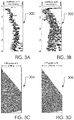
- FIG. 3A illustrates said semblance at A diagram 300 .
- FIG. 3B illustrates said semblance at B diagram 302 .
- FIG. 3C illustrates said CIP gather at A diagram 304 .
- FIG. 3D illustrates said CIP gather at B diagram 306 .
- said prestack time migration diagram 200 can comprise said semblance at A diagram 300 , said semblance at B diagram 302 , said CIP gather at A diagram 304 , said CIP gather at B diagram 306 and said CIP gather at B diagram 306 .
- FIGS. 3A-3D can comprise rms velocity semblance spectra (semblance at A diagram 300 and semblance at B diagram 302 ), and CIP gathers (CIP gather at A diagram 304 and CIP gather at B diagram 306 ).
- semblance at A diagram 300 can exhibit a distinctive set of peaks that allow picking a velocity function unambiguously, whereas the semblance spectrum at semblance at B diagram 302 can exhibit a multiplicity of peaks that can give rise to uncertainty in velocity picking.
- CIP Common-Image-Point
- the CIP gather at CIP gather at A diagram 304 can exhibit flat events that confirm the accuracy of the rms velocity field used for PSTM, whereas CIP gather at B diagram 306 can exhibit highly complex and interfering events—again indicative of the velocity uncertainty within the structurally complex portion of the line.
- This CIP gather not only can be a manifestation of the structural complexity resulting in a poor image (said prestack time migration diagram 200 ), but also is practically unusable for velocity update based on flatness of events, nor can it be used for verification of the accuracy of the rms velocity field used for PSTM.
- This disclosure presents said zero-offset wavefield synthesis workflow 100 , also referred to as “i-cube” for brevity, that provides an answer to this question in the affirmative.
- zero-offset wavefield synthesis workflow 100 can include construction of a migration cube by prestack time migration of shot gathers using a range of constant velocities.
- This migration cube can be used to pick rms velocities for prestack time migration.
- the multiplicity of semblance peaks associated with the migration cube remains to be perilous. We can sum the image panels within the migration cube over the velocity axis to obtain a composite image in time so as to preserve all events in the migration cube and avoid committing our inadvertently to a velocity field which most likely would have some uncertainty.
- FIG. 4 illustrates said migration-cube stack diagram 400 .
- said zero-offset wavefield synthesis workflow 100 can comprise said migration-cube stack output 402 .
- migration-cube stack diagram 400 can comprise a stack of the migration-cube panels.
- the resulting composite unmigrated section actually is equivalent to a zero-offset wavefield (synthesized zero-offset wavefield output 116 ), which preserves diffractions and all reflections with conflicting dips.
- the final step in the workflow is poststack time migration of the synthesized zero-offset wavefield (said time migration output 120 ).
- This disclosure shall demonstrate said zero-offset wavefield synthesis workflow 100 (the i-cube workflow) using a field data set from a thrust belt.
- FIG. 5 illustrates said calculations diagram 500 .
- said calculations diagram 500 can comprise said workflow equations 502 .
- said workflow equations 502 can comprise said first equation 502 a , said second equation 502 b , said third equation 502 c , said fourth equation 502 d and said fifth equation 502 e.
- said zero-offset wavefield synthesis workflow 100 can comprise said calculations diagram 500 .
- Said calculations diagram 500 is labeled “Back to the future: return of the DMO”. Accordingly, zero-offset wavefield synthesis workflow 100 may be considered as being inspired by the DMO workflow.
- Said zero-offset wavefield synthesis workflow 100 is based on synthesis of a zero-offset wavefield to capture and preserve all reflections and diffractions, followed by zero-offset time migration.
- workflow equations 502 first consider that by applying DMO correction to NMO-corrected CMP gathers and stacking, we obtain a close approximation to a zero-offset wavefield, which by definition includes all reflections and diffractions as symbolically described by first equation 502 a .
- the image in time obtained by the DMO workflow essentially is equivalent to the image obtained by PSTM, provided lateral velocity variations are within the bounds of time migration.
- This statement is symbolically expressed by second equation 502 b , where tmig stands for poststack time migration. Add demig to both sides of this equation to get said third equation 502 c , where demig stands for demigration—in this case, inverse of tmig.
- FIG. 6 illustrates said workflow diagram 600 .
- said migration cube output 112 can comprise said velocity panels 602 .
- Said workflow diagram 600 can comprise a graphical representation of zero-offset wavefield synthesis workflow 100 .
- Said migration cube output 112 can comprise velocity panels 602 ; wherein, zero-offset wavefield synthesis workflow 100 can perform multichannel signal processing to each among said velocity panels 602 to increase signal coherency.
- Said velocity panels 602 can comprise the X and T vectors of said migration cube output 112 .
- migration cube output 112 comprises image volume in (V, X, T) coordinates, where V can comprise the rms velocity, X can comprise the midpoint, and T can comprise the event time after migration.
- FIG. 7 illustrates said zero-offset wavefield diagram 700 .
- said zero-offset wavefield diagram 700 can comprise said zero-offset wavefield output 702 .
- said workflow diagram 600 can comprise said zero-offset wavefield diagram 700 .
- Said zero-offset wavefield diagram 700 represent data rendered from zero-offset wavefield synthesis workflow 100 .
- Said zero-offset wavefield diagram 700 can be obtained by stacking the panels of the demigration cube (said zero-offset wavefield synthesis procedure 104 b ).
- FIG. 8 illustrates said zero-offset wavefield time migration diagram 800 .
- said zero-offset wavefield time migration diagram 800 can comprise said zero-offset wavefield time migration output 802 .
- said zero-offset wavefield synthesis workflow 100 can comprise said zero-offset wavefield time migration diagram 800 .
- Said zero-offset wavefield time migration diagram 800 can comprise poststack time migration of synthesized zero-offset wavefield output 116 of zero-offset wavefield synthesis workflow 100 and workflow diagram 600 .
- Said zero-offset wavefield time migration diagram 800 can comprise the principal image in time; further, zero-offset wavefield time migration diagram 800 can be used for structural interpretation.
- FIG. 9 illustrates said zero-offset wavefield depth migration diagram 900 .
- said zero-offset wavefield depth migration diagram 900 can comprise said zero-offset wavefield depth migration output 902 .
- said zero-offset wavefield synthesis workflow 100 can comprise said zero-offset wavefield depth migration diagram 900 .
- said calculations diagram 500 can comprise said zero-offset wavefield depth migration output 902 .
- Said zero-offset wavefield depth migration diagram 900 can comprise a poststack depth migration of the synthesized zero-offset wavefield (said zero-offset wavefield diagram 700 ).
- zero-offset wavefield depth migration diagram 900 can comprise an auxiliary image in depth accompanying the principal image in time shown in said zero-offset wavefield time migration diagram 800 and can be used for structural interpretation.
- FIG. 10 illustrates a flow chart view of said migration cube procedure 102 .
- said one or more steps 1000 can comprise said first step 1000 a , said second step 1000 b , said third step 1000 c , said fourth step 1000 d , said fifth step 1000 e , said sixth step 1000 f , said seventh step 1000 g and said eighth step 1000 h.
- said migration cube procedure 102 can comprise said one or more steps 1000 .
- Said migration cube procedure 102 can be illustrated as shown in one or more steps 1000 .
- FIG. 11 illustrates a flow chart view of a computer implementation 1100 of said zero-offset wavefield synthesis workflow 100 .
- Said computer implementation 1100 can comprise said migration cube output 112 being input into a one or more computers 1102 , a portion of which are configured to implement said zero-offset wavefield synthesis workflow 100 .
- said one or more computers 1102 can comprise a one or more processors 1104 , a memory 1106 comprising a workflow application 1108 , and a communication hardware 1110 .
- said workflow application 1108 can comprise code configured to receive said migration cube output 112 and/or said shot gather data 110 , apply the steps outlined in said zero-offset wavefield synthesis workflow 100 , and generate said synthesized zero-offset wavefield output 116 and/or said time migration output 120 .
- Said one or more computers 1102 can comprise laptops, desktops, servers, mobile devices or similar.
- said one or more computers 1102 can comprise and operating system such as Linux.
- Near-surface geophysics is the use of geophysical methods to investigate small-scale features in the shallow (tens of meters) subsurface. It is closely related to applied geophysics or exploration geophysics. Methods used include seismic refraction and reflection, gravity, magnetic, electric, and electromagnetic methods. Many of these methods were developed for oil and mineral exploration but are now used for a great variety of applications, including archaeology, environmental science, forensic science, military intelligence, geotechnical investigation, treasure hunting, and hydrogeology.
- near-surface geophysics includes the study of biogeochemical cycles.” Accordingly, “near-surface” is understood to mean the layer just below the surface of the earth and above the subsurface layers of rocks. The near-surface is composed of highly heterogeneous, unconsolidated earth material. To image the subsurface, you need to remove the deleterious effect of the near-surface complexity.
- references to said short wavelength can comprise a first wavelength; said medium wavelength can comprise a second wavelength; and said long wavelength can comprise a third wavelength.
- said third wavelength is longer than said second wavelength, and said second wavelength is longer than said first wavelength.
- said first wavelength shot-receiver residual statics characterize said first wavelength
- said second wavelength shot-receiver statics characterize said second wavelength
- said third wavelength shot-receiver statics characterize said third wavelength.
- a zero-offset wavefield synthesis workflow 100 to calculate a synthesized zero-offset wavefield output 116 without the commitment to an rms velocity field output 118 to circumvent velocity uncertainty.
- Said demigration cube output 114 comprises an unmigrated volume that contains all reflections and diffractions that are present in the signal-processed shot gathers.
- Said rms velocity field output 118 comprises a one or more lateral velocity variations.
- Said migration cube output 112 comprises image volume in (V, X, T) coordinates.
- Said V comprises an rms velocity.
- Said X comprises a midpoint.
- Said T comprises an event time after migration.
- Said zero-offset wavefield synthesis procedure 104 b comprises calculating said synthesized zero-offset wavefield output 116 using said V, X and T coordinates of said demigration cube output 114 by summing over said V axis of said demigration cube output 114 to synthesize a zero-offset wavefield by said zero-offset wavefield synthesis procedure 104 b , preserving all reflections and diffractions, and avoiding uncertainty in a velocity field since events are stationary both in time and space in said demigration cube output 114 .
Landscapes
- Engineering & Computer Science (AREA)
- Remote Sensing (AREA)
- Physics & Mathematics (AREA)
- Life Sciences & Earth Sciences (AREA)
- Environmental & Geological Engineering (AREA)
- Geology (AREA)
- Acoustics & Sound (AREA)
- General Life Sciences & Earth Sciences (AREA)
- General Physics & Mathematics (AREA)
- Geophysics (AREA)
- Business, Economics & Management (AREA)
- Emergency Management (AREA)
- Radar Systems Or Details Thereof (AREA)
Abstract
Description
- Beasley, C. J. and Klotz, R., 1992, Equalization of DMO for irregular spatial sampling: 58th Ann. Internat. Mtg., Soc. Expl. Geophys., Expanded Abstracts, 970-973.
- Canales, L., 1984, Random noise reduction: 54th Ann. Internat. Mtg., Soc. Expl. Geophys., Expanded Abstracts, 525.
- Deregowski, S. M., 1982, Dip-moveout and reflector-point dispersal: Geophys. Prosp., 30, 318-322.
- Fowler, P., 1984, Velocity-independent imaging of seismic reflectors: 54th Ann. Internat. Mtg., Soc. Explor. Geophys., Expanded Abstracts, 383-385.
- Hale, D., 1984, Dip moveout by Fourier transform: Geophysics, 49, 741-757.
- Hampson, D., 1987, The discrete Radon transform: A new tool for image enhancement and noise suppression: 57th Ann. Internat. Mtg., Soc. Expl. Geophys., Expanded Abstracts, 141-143.
- Landa, E., 2013, Quantum seismic imaging, J. of Seismic Expl., 22, 295-310.
- Landa, E., S. Fomel, and T. J. Moser, 2006, path-integral seismic imaging, Geophys. Pros., 54, 491-503.
- Levin, F. K., 1971, Apparent velocity from dipping interface reflections: Geophysics, 36, 510-516.
- Ronen, J. and Claerbout, J. F., 1985, Surface-consistent residual statics estimation by stack-power maximization: Geophysics, 50, 2759-2767.
- Schleicher, J. and J. Costa, 2009, Migration velocity analysis by double-path integral migration, Geophysics, (74) 6, WCA225-231.
- Sherwood, J. W. C., Schultz, P. S., and Judson, D. R., 1978, Equalizing the stacking velocities of dipping events via Devilish: Presented at the 48th Ann. Internat. Soc. Expl. Geophys. Mtg.
- Shurtleff, R., 1984, An F-K procedure for prestack migration and velocity analysis: Presented at the 46th Ann. Mtg. European Asn. Expl. Geophys.
- Trickett, R. S., 2005, F-xy eigenimage noise suppression, Geophysics, (68) 2, 755-759.
- Yilmaz, O. and Claerbout, J. F., 1980, Prestack partial migration: Geophysics, 45, 1753-1777.
- Yilmaz, O., 2001, Seismic Data Analysis: Processing, Inversion, and Interpretation of Seismic Data, Soc. Expl. Geophys. Tulsa, Okla.
- Yilmaz, O., 2015, Engineering Seismology: with Applications to Geotechnical Investigations, Soc. Expl. Geophys. Tulsa, Okla.
- Zhang, J., and M. N. Toksoz, 1998, Nonlinear refraction traveltime tomography: Geophysics, 63, 1726{1737, http://dx.doi.org/10.1190/1.1444468.
- a zero-offset
wavefield synthesis workflow 100 - a
migration cube procedure 102 - a
demigration cube procedure 104 - a
demigration cube calculation 104 a - a zero-offset
wavefield synthesis procedure 104 b - an rms velocity
field calculation procedure 106 - an rms
velocity field calculation 106 a - a
time migration calculation 108 - a shot gather
data 110 - a
migration cube output 112 - a
demigration cube output 114 - a synthesized zero-offset
wavefield output 116 - an rms
velocity field output 118 - a
time migration output 120 - a prestack time migration diagram 200
- a one or more measurement points 202
- a
measurement point A 202 a - a
measurement point B 202 b - a prestack
time migration output 204 - a semblance at A diagram 300
- a semblance at B diagram 302
- a CIP gather at A diagram 304
- a CIP gather at B diagram 306
- a migration-cube stack diagram 400
- a migration-
cube stack output 402 - a calculations diagram 500
- a workflow equations 502
- a
first equation 502 a - a
second equation 502 b - a
third equation 502 c - a
fourth equation 502 d - a
fifth equation 502 e - a workflow diagram 600
- a
velocity panels 602 - a zero-offset wavefield diagram 700
- a zero-offset
wavefield output 702 - a zero-offset wavefield time migration diagram 800
- a zero-offset wavefield
time migration output 802 - a zero-offset wavefield depth migration diagram 900
- a zero-offset wavefield
depth migration output 902 - a one or more steps 1000
- a
first step 1000 a - a
second step 1000 b - a
third step 1000 c - a
fourth step 1000 d - a
fifth step 1000 e - a
sixth step 1000 f - a
seventh step 1000 g - an
eighth step 1000 h - a
computer implementation 1100 - a one or
more computers 1102 - a one or
more processors 1104 - a
memory 1106 - a workflow application 1108
- a
communication hardware 1110
Claims (20)
Priority Applications (1)
| Application Number | Priority Date | Filing Date | Title |
|---|---|---|---|
| US15/862,686 US11150372B2 (en) | 2017-09-25 | 2018-01-05 | Circumventing velocity uncertainty in imaging complex structures i-cube |
Applications Claiming Priority (2)
| Application Number | Priority Date | Filing Date | Title |
|---|---|---|---|
| US201762562611P | 2017-09-25 | 2017-09-25 | |
| US15/862,686 US11150372B2 (en) | 2017-09-25 | 2018-01-05 | Circumventing velocity uncertainty in imaging complex structures i-cube |
Publications (2)
| Publication Number | Publication Date |
|---|---|
| US20190094399A1 US20190094399A1 (en) | 2019-03-28 |
| US11150372B2 true US11150372B2 (en) | 2021-10-19 |
Family
ID=65808245
Family Applications (1)
| Application Number | Title | Priority Date | Filing Date |
|---|---|---|---|
| US15/862,686 Expired - Fee Related US11150372B2 (en) | 2017-09-25 | 2018-01-05 | Circumventing velocity uncertainty in imaging complex structures i-cube |
Country Status (1)
| Country | Link |
|---|---|
| US (1) | US11150372B2 (en) |
Families Citing this family (5)
| Publication number | Priority date | Publication date | Assignee | Title |
|---|---|---|---|---|
| US10782430B2 (en) * | 2018-01-12 | 2020-09-22 | Cgg Services Sas | Method for seismic exploration using a multiple-inclusive source wavelet |
| US11221425B1 (en) * | 2020-07-08 | 2022-01-11 | Saudi Arabian Oil Company | Generating a model for seismic velocities in a subsurface region using inversion with lateral variations |
| CN116009060B (en) * | 2021-10-19 | 2026-01-09 | 中国石油化工股份有限公司 | Earthquake data acquisition methods, devices, electronic equipment and storage media |
| CN116009093A (en) * | 2021-10-21 | 2023-04-25 | 中国石油化工股份有限公司 | A real surface migration method, electronic equipment, medium and device |
| CN118330733B (en) * | 2024-06-12 | 2024-08-06 | 中国海洋大学 | Kirchhoff integral offset imaging method based on cross-correlation correction of imaging gather |
Citations (1)
| Publication number | Priority date | Publication date | Assignee | Title |
|---|---|---|---|---|
| US20140133275A1 (en) * | 2012-11-13 | 2014-05-15 | Total E&P Usa, Inc. | Process for Creating Image Gathers |
-
2018
- 2018-01-05 US US15/862,686 patent/US11150372B2/en not_active Expired - Fee Related
Patent Citations (1)
| Publication number | Priority date | Publication date | Assignee | Title |
|---|---|---|---|---|
| US20140133275A1 (en) * | 2012-11-13 | 2014-05-15 | Total E&P Usa, Inc. | Process for Creating Image Gathers |
Non-Patent Citations (3)
| Title |
|---|
| Clapp, Geologically Constrained Migration Velocity Analysis, Mar. 2001, Stanford University, pp. 1-176 (Year: 2001). * |
| Rickett et al., Offset and angle-domain common image-point gathers for shot-profile migration, 2002, Geophysics, vol. 67 No. 3, pp. 883-889 (Year: 2002). * |
| Yilmaz, Circumventing velocity uncertainty in imaging complex structures, Jan. 2018, The Leading Edge, pp. 14-18 (Year: 2018). * |
Also Published As
| Publication number | Publication date |
|---|---|
| US20190094399A1 (en) | 2019-03-28 |
Similar Documents
| Publication | Publication Date | Title |
|---|---|---|
| EP3607359B1 (en) | Generating common image gather using wave-field separation | |
| Zhang et al. | Amplitude-preserving reverse time migration: From reflectivity to velocity and impedance inversion | |
| US10620331B2 (en) | Reverse time migration in anisotropic media with stable attenuation compensation | |
| US10267937B2 (en) | Generating subterranean imaging data based on vertical seismic profile data and ocean bottom sensor data | |
| Mallick et al. | Amplitude-variation-with-offset and prestack-waveform inversion: A direct comparison using a real data example from the Rock Springs Uplift, Wyoming, USA | |
| US11150372B2 (en) | Circumventing velocity uncertainty in imaging complex structures i-cube | |
| US10725190B2 (en) | Seismic data processing using matching filter based cost function optimization | |
| EP3529640B1 (en) | Generating subterranean imaging data based on vertical seismic profile data and ocean bottom sensor data | |
| EP3586169B1 (en) | Generating geophysical images using directional oriented wavefield imaging | |
| McLeman et al. | Superior resolution through multiparameter FWI imaging: A new philosophy in seismic processing and imaging | |
| US20180059276A1 (en) | System and method for focusing seismic images | |
| CN113805237A (en) | Method and system for offset land cross-spread seismic using compressed sensing models | |
| Liu et al. | Oriented pre-stack inverse Q filtering for resolution enhancements of seismic data | |
| Zhang et al. | Common-image gathers in the incident phase-angle domain from reverse time migration in 2D elastic VTI media | |
| Li et al. | Target-oriented high-resolution elastic full-waveform inversion with an elastic redatuming method | |
| Yang et al. | Approximating the Gauss–Newton Hessian using a space-wavenumber filter and its applications in least-squares seismic imaging | |
| Jaiswal et al. | Seismic imaging of the Naga thrust using multiscale waveform inversion | |
| GB2590177A (en) | Methods and devices performing adaptive subtraction of multiples | |
| Zhao et al. | Model-based radiation pattern correction for interferometric redatuming in 4D seismic | |
| Yilmaz et al. | A unified 3-D seismic workflow | |
| Yilmaz | Circumventing velocity uncertainty in imaging complex structures | |
| Tang et al. | Target-oriented wavefield tomography using synthesized Born data | |
| Wu et al. | Attenuation compensation in multicomponent Gaussian beam prestack depth migration | |
| Behm et al. | Blind deconvolution of multichannel recordings by linearized inversion in the spectral domain | |
| Bartolome et al. | Using the OBS wide-angle reflection/refraction velocities to perform a pre-stack depth migration image of the “single bubble” multichannel seismic: example of the Moroccan margin |
Legal Events
| Date | Code | Title | Description |
|---|---|---|---|
| FEPP | Fee payment procedure |
Free format text: ENTITY STATUS SET TO UNDISCOUNTED (ORIGINAL EVENT CODE: BIG.); ENTITY STATUS OF PATENT OWNER: MICROENTITY |
|
| FEPP | Fee payment procedure |
Free format text: ENTITY STATUS SET TO SMALL (ORIGINAL EVENT CODE: SMAL); ENTITY STATUS OF PATENT OWNER: MICROENTITY Free format text: ENTITY STATUS SET TO MICRO (ORIGINAL EVENT CODE: MICR); ENTITY STATUS OF PATENT OWNER: MICROENTITY |
|
| STPP | Information on status: patent application and granting procedure in general |
Free format text: DOCKETED NEW CASE - READY FOR EXAMINATION |
|
| STPP | Information on status: patent application and granting procedure in general |
Free format text: NON FINAL ACTION MAILED |
|
| STPP | Information on status: patent application and granting procedure in general |
Free format text: RESPONSE TO NON-FINAL OFFICE ACTION ENTERED AND FORWARDED TO EXAMINER |
|
| STPP | Information on status: patent application and granting procedure in general |
Free format text: NOTICE OF ALLOWANCE MAILED -- APPLICATION RECEIVED IN OFFICE OF PUBLICATIONS |
|
| FEPP | Fee payment procedure |
Free format text: ENTITY STATUS SET TO MICRO (ORIGINAL EVENT CODE: MICR); ENTITY STATUS OF PATENT OWNER: MICROENTITY |
|
| STPP | Information on status: patent application and granting procedure in general |
Free format text: PUBLICATIONS -- ISSUE FEE PAYMENT VERIFIED |
|
| STCF | Information on status: patent grant |
Free format text: PATENTED CASE |
|
| FEPP | Fee payment procedure |
Free format text: MAINTENANCE FEE REMINDER MAILED (ORIGINAL EVENT CODE: REM.); ENTITY STATUS OF PATENT OWNER: MICROENTITY |
|
| LAPS | Lapse for failure to pay maintenance fees |
Free format text: PATENT EXPIRED FOR FAILURE TO PAY MAINTENANCE FEES (ORIGINAL EVENT CODE: EXP.); ENTITY STATUS OF PATENT OWNER: MICROENTITY |
|
| STCH | Information on status: patent discontinuation |
Free format text: PATENT EXPIRED DUE TO NONPAYMENT OF MAINTENANCE FEES UNDER 37 CFR 1.362 |
|
| FP | Lapsed due to failure to pay maintenance fee |
Effective date: 20251019 |