US11149709B2 - Method to reduce noise and vibration in a jointed wind turbine blade, and associated wind turbine blade - Google Patents
Method to reduce noise and vibration in a jointed wind turbine blade, and associated wind turbine blade Download PDFInfo
- Publication number
- US11149709B2 US11149709B2 US16/139,185 US201816139185A US11149709B2 US 11149709 B2 US11149709 B2 US 11149709B2 US 201816139185 A US201816139185 A US 201816139185A US 11149709 B2 US11149709 B2 US 11149709B2
- Authority
- US
- United States
- Prior art keywords
- wise
- blade
- offset
- wind turbine
- blade segment
- Prior art date
- Legal status (The legal status is an assumption and is not a legal conclusion. Google has not performed a legal analysis and makes no representation as to the accuracy of the status listed.)
- Active, expires
Links
Images


Classifications
-
- F03D1/0683—
-
- F—MECHANICAL ENGINEERING; LIGHTING; HEATING; WEAPONS; BLASTING
- F03—MACHINES OR ENGINES FOR LIQUIDS; WIND, SPRING, OR WEIGHT MOTORS; PRODUCING MECHANICAL POWER OR A REACTIVE PROPULSIVE THRUST, NOT OTHERWISE PROVIDED FOR
- F03D—WIND MOTORS
- F03D1/00—Wind motors with rotation axis substantially parallel to the air flow entering the rotor
- F03D1/06—Rotors
- F03D1/065—Rotors characterised by their construction elements
- F03D1/0675—Rotors characterised by their construction elements of the blades
-
- F—MECHANICAL ENGINEERING; LIGHTING; HEATING; WEAPONS; BLASTING
- F01—MACHINES OR ENGINES IN GENERAL; ENGINE PLANTS IN GENERAL; STEAM ENGINES
- F01D—NON-POSITIVE DISPLACEMENT MACHINES OR ENGINES, e.g. STEAM TURBINES
- F01D25/00—Component parts, details, or accessories, not provided for in, or of interest apart from, other groups
- F01D25/04—Antivibration arrangements
- F01D25/06—Antivibration arrangements for preventing blade vibration
-
- F—MECHANICAL ENGINEERING; LIGHTING; HEATING; WEAPONS; BLASTING
- F05—INDEXING SCHEMES RELATING TO ENGINES OR PUMPS IN VARIOUS SUBCLASSES OF CLASSES F01-F04
- F05B—INDEXING SCHEME RELATING TO WIND, SPRING, WEIGHT, INERTIA OR LIKE MOTORS, TO MACHINES OR ENGINES FOR LIQUIDS COVERED BY SUBCLASSES F03B, F03D AND F03G
- F05B2240/00—Components
- F05B2240/20—Rotors
- F05B2240/30—Characteristics of rotor blades, i.e. of any element transforming dynamic fluid energy to or from rotational energy and being attached to a rotor
- F05B2240/301—Cross-section characteristics
-
- F—MECHANICAL ENGINEERING; LIGHTING; HEATING; WEAPONS; BLASTING
- F05—INDEXING SCHEMES RELATING TO ENGINES OR PUMPS IN VARIOUS SUBCLASSES OF CLASSES F01-F04
- F05B—INDEXING SCHEME RELATING TO WIND, SPRING, WEIGHT, INERTIA OR LIKE MOTORS, TO MACHINES OR ENGINES FOR LIQUIDS COVERED BY SUBCLASSES F03B, F03D AND F03G
- F05B2240/00—Components
- F05B2240/20—Rotors
- F05B2240/30—Characteristics of rotor blades, i.e. of any element transforming dynamic fluid energy to or from rotational energy and being attached to a rotor
- F05B2240/302—Segmented or sectional blades
-
- F—MECHANICAL ENGINEERING; LIGHTING; HEATING; WEAPONS; BLASTING
- F05—INDEXING SCHEMES RELATING TO ENGINES OR PUMPS IN VARIOUS SUBCLASSES OF CLASSES F01-F04
- F05B—INDEXING SCHEME RELATING TO WIND, SPRING, WEIGHT, INERTIA OR LIKE MOTORS, TO MACHINES OR ENGINES FOR LIQUIDS COVERED BY SUBCLASSES F03B, F03D AND F03G
- F05B2260/00—Function
- F05B2260/84—Modelling or simulation
-
- F—MECHANICAL ENGINEERING; LIGHTING; HEATING; WEAPONS; BLASTING
- F05—INDEXING SCHEMES RELATING TO ENGINES OR PUMPS IN VARIOUS SUBCLASSES OF CLASSES F01-F04
- F05B—INDEXING SCHEME RELATING TO WIND, SPRING, WEIGHT, INERTIA OR LIKE MOTORS, TO MACHINES OR ENGINES FOR LIQUIDS COVERED BY SUBCLASSES F03B, F03D AND F03G
- F05B2260/00—Function
- F05B2260/96—Preventing, counteracting or reducing vibration or noise
-
- Y—GENERAL TAGGING OF NEW TECHNOLOGICAL DEVELOPMENTS; GENERAL TAGGING OF CROSS-SECTIONAL TECHNOLOGIES SPANNING OVER SEVERAL SECTIONS OF THE IPC; TECHNICAL SUBJECTS COVERED BY FORMER USPC CROSS-REFERENCE ART COLLECTIONS [XRACs] AND DIGESTS
- Y02—TECHNOLOGIES OR APPLICATIONS FOR MITIGATION OR ADAPTATION AGAINST CLIMATE CHANGE
- Y02E—REDUCTION OF GREENHOUSE GAS [GHG] EMISSIONS, RELATED TO ENERGY GENERATION, TRANSMISSION OR DISTRIBUTION
- Y02E10/00—Energy generation through renewable energy sources
- Y02E10/70—Wind energy
- Y02E10/72—Wind turbines with rotation axis in wind direction
Definitions
- the present subject matter relates generally to wind turbine rotor blades and, more particularly, to a spar configuration between segments of a jointed blade designed to reduce noise and vibration generated at the joint profile.
- Wind power is considered one of the cleanest, most environmentally friendly energy sources presently available, and wind turbines have gained increased attention in this regard.
- a modern wind turbine typically includes a tower, generator, gearbox, nacelle, and one or more rotor blades.
- the rotor blades capture kinetic energy from wind using known foil principles and transmit the kinetic energy through rotational energy to turn a shaft coupling the rotor blades to a gearbox, or if a gearbox is not used, directly to the generator.
- the generator then converts the mechanical energy to electrical energy that may be deployed to a utility grid.
- Wind turbine rotor blades generally include a body shell formed by two shell halves of a composite laminate material.
- the shell halves are generally manufactured using molding processes and then coupled together along the corresponding ends of the rotor blade.
- the body shell is relatively lightweight and has structural properties (e.g., stiffness, buckling resistance, and strength) which are not configured to withstand the bending moments and other loads exerted on the rotor blade during operation.
- wind turbines for wind power generation have increased in size to achieve improvement in power generation efficiency and to increase the amount of power generation.
- wind turbine rotor blades have also significantly increased in size (e.g., up to 55 meters in length), resulting in difficulties in integral manufacture as well as conveyance and transport of the blades to a site.
- the industry is developing sectional wind turbine rotor blades wherein separate blade segments are manufactured and transported to a site for assembly into a complete blade (a “jointed” blade).
- the blade segments are joined together by a beam structure that extends span-wise from one blade segment into a receiving section of the other blade segment.
- a beam structure that extends span-wise from one blade segment into a receiving section of the other blade segment.
- the beam structure forms a portion of the internal support structure for the blade and includes a shear web connected with a suction side spar cap and a pressure side spar cap.
- Multiple bolt joints are used to connect the beam structure with the receiving section in the second blade segment, including a span-wise bolt on the end face of the beam and at least one chord-wise bolt through the beam structure spaced from the joint line between the blade segments.
- US Patent Publication No. 2011/0091326 describes a jointed blade wherein a first blade portion and a second blade portion extend in opposite directions from a joint.
- Each blade portion includes a spar section forming a structural member of the blade and running lengthways, wherein the first blade portion and the second blade portion are structurally connected by a spar bridge that joins the spar sections.
- the spar bridge may be an extension of one of the spar sections that is received in a receiving spar section of the other blade portion.
- This configuration also uses a threaded bolt extending from the end face of the spar to connect and tension the spar in the receiving spar section.
- jointed blade configurations are susceptible to increased vibration and noise generation resulting from the joint. Relative deflections between the root-end blade segment and the tip-end blade segment result in flap-wise offsets between the shell members at the joint line. This situation is particularly present in the jointed blade designs that employ a chord-wise bolt or pin spaced (span-wise) from the joint line to transfer loads from the chord-wise bolt into the blade shells. This span-wise spacing, in combination with a difference in stiffness and orientation between the blade segment and jointed internal support structure, results in the flap-wise offsets between the shell members.
- torsion forces are also generated at the jointed structure that generate a twist offset between the shell members, particularly at the trailing edge of the blade.
- the flap-wise and/or twist-wise offsets at the joint line result in generation of turbulent vortices, which can add significantly to vibration and noise being generated at the joint line. Additionally, twist offsets can reduce power performance of the wind turbine at the design condition.
- the present disclosure is directed to a method to reduce noise and vibration in a joint configuration between a first blade segment and a second blade segment of a jointed wind turbine rotor blade.
- Each of the first and second blade segments include a shell member having a pressure side shell component and a suction side shell component.
- the method includes determining an actual offset that is induced at a chord-wise joint line between the shell members of the first and second blade segments at a load condition on the jointed wind turbine rotor blade, wherein the actual offset is any one or combination of a flap-wise offset generated by a flap-wise force, a twist-wise offset generated by a twist-wise force, or a yawl-wise offset generated by a yawl-wise force.
- a modified configuration of the joint structure is defined at a no-load condition on the wind turbine rotor blade that compensates at least partially for one or more of the actual offset components at the load condition.
- the first and second blade segments are then connected or joined with the modified configuration of the joint structure, wherein at the load condition, the modified configuration of the joint structure reduces one or both of the flap-wise offset and the twist-wise offset between the shell members of the first and second blade segments.
- the joint structure includes a beam structure extending span-wise from the first blade segment and a receiving section formed in the second blade segment for receipt of the beam structure, wherein the modified configuration of the joint structure includes a change in connection between the beam structure and the receiving section.
- the first blade segment may be a tip-end blade segment
- the second blade segment is a root-end blade segment.
- the joint structure may include a chord-wise pin extending through the beam structure and the receiving section at a location spaced from the joint line in a span-wise direction.
- the modified configuration of the joint structure may include an alternate location of the chord-wise pin that compensates for one or more of the flap-wise offset, twist-wise offset, or yawl-wise offset at the load condition.
- the alternate location may be selected to produce one or more of a counter flap-wise offset, counter twist-wise offset, or counter yawl-wise offset at the no-load condition.
- the step of determining the modified configuration of the joint structure includes determining a combination of materials in the joint structure that also may contribute to reducing one or more of the flap-wise offset, twist-wise offset, or yawl-wise offset at the load condition.
- This combination of materials may be a stand-alone modification to the joint structure, or may be in combination with a change in location of the chord-wise pin, or other alteration of the joint structure.
- the change is materials may include, for example adding or removing materials from the joint structure to achieve a stiffness or torsion resistance that reduces one or more of the flap-wise offset, twist-wise offset, or yawl-wise offset at the load condition.
- the load condition is the load when approaching rated output speed of a wind turbine on which the jointed wind turbine rotor blade is used, and the flap-wise offset, twist-wise offset, or yawl-wise offset at the load condition are based on an average of the respective offsets at the rated output speed over a certain range of wind speed.
- This determination may be an actual measurement from operational wind turbines, or may be made via computer modeling of the jointed wind turbine blade at the load condition.
- the present invention also encompasses a jointed wind turbine rotor blade with joint structure having the characteristics discussed above.
- a jointed wind turbine rotor blade with joint structure having the characteristics discussed above.
- such a blade includes a first blade segment and a second blade segment extending in opposite directions from a chord-wise joint line, each of the blade segments having a pressure side shell member and a suction side shell member.
- a joint structure is provided between the first blade segment and the second blade segment, wherein the joint structure includes a counter offset at a no-load condition on the rotor blade that compensates for one or more of a flap-wise offset, twist-wise offset, or yawl-wise offset at a load condition.
- the joint structure reduces noise and vibration generated by the jointed wind turbine rotor blade at the load condition.
- the joint structure includes a beam structure extending span-wise from the first blade segment, and a receiving section formed in the second blade segment for receipt of the beam structure.
- the first blade segment may be a tip-end blade segment, while the second blade segment is a root-end blade segment.
- the joint structure may include a chord-wise pin extending through the beam structure and the receiving section at a location spaced from the joint line in a span-wise direction, wherein the chord-wise pin is at a location that generates at least partly the counter offset at the no-load condition.
- the joint structure includes a combination of materials that may also aid in reducing one or more of the flap-wise offset, twist-wise offset, or yawl-wise offset at the load condition.
- This combination of materials may be a stand-alone modification to the joint structure, or may be in combination with a change in location of the chord-wise pin.
- the change is materials may include, for example adding or removing materials from the joint structure to achieve a stiffness or torsion resistance that reduces one or both of the flap-wise offset and the twist-wise offset at the load condition.
- FIG. 1 illustrates a perspective view of a wind turbine that may utilize a jointed wind turbine blade according to the present disclosure
- FIG. 2 illustrates a rotor blade having a first blade segment and a second blade segment, and joint structure that connects the blade segments;
- FIG. 3 is a perspective view of an embodiment of a first blade segment with joint structure
- FIG. 4 is a perspective view of an embodiment of a second blade segment with joint structure
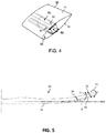
- FIG. 5 is a perspective view of a jointed wind turbine blade depicting with flap-wise and twist-wise forces acting on the blade;
- FIG. 6 is a partial perspective view of the joint line between blade segments depicting a flap-wise induced offset between the blade segments at the joint line;
- FIG. 7 is a partial perspective view of the joint line between blade segments depicting a flap-wise and twist-wise induced offset between the blade segments at the joint line;
- FIGS. 8 a through 8 d are sequential diagram views of an embodiment for modifying the joint structure in a jointed wind turbine blade to compensate for flap-wise induced offsets at a load condition on the blade;
- FIGS. 9 a through 9 d are sequential diagram views of an embodiment for modifying the joint structure in a jointed wind turbine blade to compensate for twist-wise induced offsets at a load condition on the blade.
- the present subject matter is directed to jointed wind turbine rotor blades having a modified joint structure configuration that serves to compensate for or counter one or both of flap-wise and twist-wise offsets between the blade segments at a load condition on the rotor blade.
- a modified joint structure configuration that serves to compensate for or counter one or both of flap-wise and twist-wise offsets between the blade segments at a load condition on the rotor blade.
- FIG. 1 is a side view of an exemplary wind turbine 10 that may use jointed wind turbine rotor blades in accordance with an embodiment of the present invention.
- the wind turbine 10 is a horizontal-axis wind turbine.
- the wind turbine 10 may be a vertical-axis wind turbine.
- the wind turbine 10 includes a tower 12 that extends from a support surface 14 , a nacelle 16 mounted on the tower 12 , a generator 18 positioned within the nacelle 16 , a gearbox 20 coupled to the generator 18 , and a rotor 22 that is rotationally coupled to the gearbox 20 with a rotor shaft 24 .
- the rotor 22 includes a rotatable hub 26 and at least one rotor blade 28 coupled to and extending outward from the rotatable hub 26 . As shown, the rotor blade 28 includes a blade tip 17 to a blade root 19 .
- a jointed rotor blade 28 is depicted having a first blade segment 30 and a second blade segment 32 in accordance with aspects of the present technology.
- the first blade segment 30 and the second blade segment 32 extend in opposite directions from a chord-wise joint line 34 .
- Each of the blade segments 30 , 32 includes a pressure side shell member 31 and a suction side shell member 33 .
- the first blade segment 30 and the second blade segment 32 are connected by an internal support structure 36 extending into both blade segments 30 , 32 to facilitate joining of the blade segments 30 , 32 .
- the arrow 38 shows that the segmented rotor blade 28 in the illustrated example includes two blade segments 30 , 32 and that these blade segments 30 , 32 are joined by inserting the internal support structure 36 into the second blade segment 32 .
- the first blade segment includes a beam structure 40 that forms a portion of the internal support structure 36 and extends lengthways (e.g., span-wise) for structurally connecting with the internal support structure 36 in the second blade segment 32 .
- the beam structure 40 may be integrally formed with the first blade segment 30 as an extension protruding from a spar section 42 , thereby forming an extended spar section.
- the beam structure 40 includes at least one interconnecting web 44 (e.g., a shear web) connected with a suction side spar cap 46 and a pressure side spar cap 48 .
- the beam structure 40 is formed as a box-type structure having opposite interconnecting webs 44 .
- the first blade segment 30 may include one or more first bolt joints (also referred to as “pins”) towards a first end 54 of the beam structure 40 .
- a bolt 52 may be located on the end 54 of the beam structure 40 and oriented in a span-wise direction.
- the first blade segment 30 may also include a bolt joint slot 50 located on the beam structure 40 proximate to the chord-wise joint 34 and oriented in a chord-wise direction. There may be a bushing within the bolt joint slot 50 arranged in a tight interference fit with a bolt tube or pin 53 used to connect the second blade segment 32 to first blade segment 30 . It should be appreciated that any combination of bolt tubes 52 , 53 and bolt slots 50 may be configured between the beam structure 40 and a receiving section 60 ( FIG. 4 ) for the purpose of interconnecting the first 30 and second 32 blade segments.
- the second blade segment 32 , the internal support structure 36 includes a receiving section 60 extending lengthways (span-wise) within the second blade segment 32 for receiving the beam structure 40 of the first blade segment 30 .
- the receiving section 60 includes multiple spar structure components 66 that extend lengthways for connecting with the beam structure 40 of the first blade segment 30 along a length of the receiving section 60 .
- the receiving section 60 includes any combination of bolt slots 50 or bolts 52 , 53 for interconnecting with corresponding bolts or slots of the beam structure 40 .
- a bolt slot is configured in a distal end (away from the chord-wise joint 34 ) of the receiving section 60 for receipt of the bolt 52 provided on the end 54 of the beam structure 40 .
- FIG. 5 depicts the concepts of flap-wise 71 , twist-wise 73 , and yawl-wise 75 forces acting on the jointed wind turbine blade, wherein such forces can respectively generate a flap-wise offset 70 ( FIG. 6 ), a twist-wise offset 72 ( FIG. 7 ), and a yawl-wise offset 77 ( FIG. 6 ) between the shell components of the first and second blade segments 30 , 32 at the chord-wise joint 34 .
- These offset components 70 , 72 , and 77 can combine to induce an actual offset 68 between the shell components.
- the flap-wise forces 71 tend to act uniformly across the chord aspect of the first blade segment 30 causing the first blade segment 30 to essentially “bend” towards the second blade segment 32 and displace the shell members 31 in a vertical direction 70 along the chord-wise joint 34 .
- the twist-wise forces 73 tend to generate a twisting of the first blade segment 30 relative to the second blade segment 32 along a span-wise axis of the blade resulting in a twist-wise offset 72 of the shell members 31 along the chord-wise joint 34 .
- the yawl-wise forces 75 tend to generate a side-ways movement of the first blade segment 30 relative to the second blade segment 32 transverse to the span-wise axis of the blade resulting in a yawl-wise offset 77 of the shell members 31 along the chord-wise joint 34 .
- these induced offsets 70 , 72 , 77 can generate excessive vibrations and noise in the blade 28 at operational load on the wind turbine (load on the turbine blades 28 when the wind turbine 10 is operating in the rated power output range of the power curve).
- FIG. 6 depicts the actual offset 68 as a combination of the flap-wise offset 70 and the yawl-offset 77 .
- FIG. 7 depicts the actual offset 68 as a combination of the flap-wise offset 70 , the twist-wise offset 72 , and the yawl-wise offset 77 . It should be appreciated that the actual offset 68 may be induced from any one or combination of the offset components 70 , 72 , and 77 .
- the blades 28 may be designed with a no-load moderate sweep inboard (closer to blade root) relative to blade pitch axis P, while the outboard section (closer to the blade tip) may be swept aft up to 10 degrees (angle ⁇ in FIG. 5 ) relative to pitch axis P.
- FIGS. 8A through 8 d determination and compensation for a flap-wise offset 70 induced in the blade 28 under load is depicted in accordance with aspects of the present disclosure.
- FIGS. 9 a through 9 d determination and compensation for a twist-wise offset 72 induced in the blade 28 under load is depicted. It should be appreciated that similar methods can be employed for determination and compensation for the yawl-wise offset.
- FIGS. 8 a and 9 a the jointed blade 28 is depicted at the chord-wise joint 34 in an initial unloaded condition wherein an initial negligible flap-wise or twist-wise offset is induced in the blade at the joint 34 .
- FIG. 8 b depicts the same jointed blade 28 at an initial loaded condition, for example under load at rated power of the wind turbine, wherein a flap-wise offset 70 is depicted between the shell members of the first blade segment 30 and the second blade segment 32 at the chord-wise joint 34 .
- FIG. 8 b depicts the same jointed blade 28 at an initial loaded condition, for example under load at rated power of the wind turbine, wherein a flap-wise offset 70 is depicted between the shell members of the first blade segment 30 and the second blade segment 32 at the chord-wise joint 34 .
- FIG. 8 b depicts the same jointed blade 28 at an initial loaded condition, for example under load at rated power of the wind turbine, wherein a flap-wise offset 70 is depicted between the shell members
- FIG. 9 b depicts the jointed blade 28 in an initial loaded condition, for example under load when approaching or at rated power of the wind turbine, wherein a twist-wise offset 72 is depicted between the shell members of the first blade segment 30 and the second blade segment 32 at the chord-wise joint 34 .
- the present method includes determining the magnitude of one or both of the flap-wise offset 70 and twist-wise offset 72 . This determination may be done by measurement of the actual offset at the chord-wise joint 34 with sensors, camera, and so forth, when the blade 28 (or similar blade) is under load. Alternatively, the actual offset may be determined via a suitable modeling program.
- the actual offset 68 at the chord-wise joint 34 may be a combination of the flap-wise offset 70 , the twist-wise offset 72 , and the yawl-wise offset 77 . Also, any one of these offsets may be negligible, wherein the actual offset is due primarily to one or a combination of the other offsets under load on the blade 28 .
- a modified configuration of the joint structure 36 is defined at a no-load condition on the blade 28 that will compensate for the induced offset.
- This modified configuration may only compensate for one of the flap-wise offset 70 or the twist-wise offset 72 , but preferably compensates for both types of offsets 70 , 72 .
- the present methods encompass the scenario wherein the actual offset 68 is determined empirically or via computer modeling for a particular type of blade at a defined location, and this offset 68 is then used to define the modified configuration for a subsequent number of blades 28 . It is not necessary to determine the actual offset and modified configuration on an individual basis for every blade 28 .
- the modified configuration of the joint structure 36 may include determining a combination of materials in the joint structure 36 that reduces one or both of the flap-wise offset 70 and the twist-wise offset 72 at the load condition.
- This combination of materials may be a stand-alone modification to the joint structure, or may be in combination with a change in location of the components of the joint structure 36 , as described below.
- the change is materials may include, for example adding or removing materials from the joint structure 36 to achieve a stiffness or torsion resistance that reduces one or both of the flap-wise offset 70 and the twist-wise offset 72 at the load condition.
- FIG. 8 c depicts an embodiment wherein the joint structure 36 is structurally modified in an unloaded state of the blade 26 to compensate for the induced flap-wise offset 70 ( FIG. 8 b ) at a load condition.
- the joint structure 36 includes the beam structure 40 extending span-wise from the first blade segment 30 (tip-end segment) and a receiving section 60 formed in the second blade segment 32 (root-end segment) for receipt of the beam structure 40 .
- the modified configuration of the joint structure 36 includes a change in connection between the beam structure 40 and the receiving section 60 .
- the joint structure 36 includes a chord-wise pin 53 extending through the beam structure 40 and the receiving section 60 at a location spaced from the joint line 34 in a span-wise direction.
- chord-wise pin 53 compensates for the flap-wise offset 70 at the load condition, wherein the alternate location is selected to produce a counter flap-wise offset 76 at the no-load condition on the blade 28 .
- the chord-wise pin 53 may be lowered or raised towards the pressure or suction side of the blade 28 relative to the initial position depicted in FIG. 8 a to produce the counter flap-wise offset 78 .
- FIG. 9 c depicts an embodiment wherein the joint structure 36 is structurally modified in an unloaded state of the blade 26 to compensate for the induced twist-wise offset 72 ( FIG. 9 b ) at a load condition.
- the modified configuration of the joint structure 36 includes a change in connection between the beam structure 40 and the receiving section 60 .
- the joint structure 36 includes the chord-wise pin 53 extending through the beam structure 40 and the receiving section 60 at a location spaced from the joint line 34 in a span-wise direction.
- An alternate location of the chord-wise pin 53 is determined that compensates for the twist-wise offset 72 at the load condition, wherein the alternate location is selected to produce a counter twist-wise offset 78 at the no-load condition on the blade 28 .
- the chord-wise pin 53 may be rotated from the initial orientation depicted in FIG. 9 a to the modified position in FIG. 9 c to produce the counter twist-wise offset 78 .
- FIG. 8 c depicts the modified assembled jointed blade 28 in an unloaded state
- FIG. 8 d depicts the blade 28 under load wherein the flap-wise offset 70 present in FIG. 8 b has been compensated for by the modifications depicted in FIG. 8 c
- FIG. 9 c depicts the modified assembled jointed blade 28 in an unloaded state
- FIG. 9 d depicts the blade 28 under load wherein the twist-wise offset 72 present in FIG. 9 b has been compensated for by the modifications depicted in FIG. 9 c.
- the present invention also encompasses a jointed wind turbine rotor blade 28 with joint structure 36 having the characteristics discussed above.
Landscapes
- Engineering & Computer Science (AREA)
- Mechanical Engineering (AREA)
- General Engineering & Computer Science (AREA)
- Life Sciences & Earth Sciences (AREA)
- Sustainable Development (AREA)
- Sustainable Energy (AREA)
- Chemical & Material Sciences (AREA)
- Combustion & Propulsion (AREA)
- Wind Motors (AREA)
- Turbine Rotor Nozzle Sealing (AREA)
Abstract
Description
Claims (14)
Priority Applications (9)
| Application Number | Priority Date | Filing Date | Title |
|---|---|---|---|
| US16/139,185 US11149709B2 (en) | 2018-09-24 | 2018-09-24 | Method to reduce noise and vibration in a jointed wind turbine blade, and associated wind turbine blade |
| EP19780475.0A EP3857049B1 (en) | 2018-09-24 | 2019-09-19 | Method to reduce noise and vibration in a jointed wind turbine blade, and associated wind turbine blade |
| ES19780475T ES2937134T3 (en) | 2018-09-24 | 2019-09-19 | Method for reducing noise and vibrations in a composite wind turbine blade, and associated wind turbine blade |
| CN201980077257.8A CN113039357B (en) | 2018-09-24 | 2019-09-19 | Method of reducing noise and vibration in a joined wind turbine blade and associated wind turbine blade |
| DK19780475.0T DK3857049T3 (en) | 2018-09-24 | 2019-09-19 | METHOD FOR REDUCING NOISE AND VIBRATION IN A JOINED WIND TURBINE BLADE AND ASSOCIATED WIND TURBINE BLADE |
| BR112021005528-2A BR112021005528B1 (en) | 2018-09-24 | 2019-09-19 | METHOD FOR REDUCING NOISE AND VIBRATION OF ARTICULATED WIND TURBINE ROTOR BLADE |
| CA3113641A CA3113641A1 (en) | 2018-09-24 | 2019-09-19 | Method to reduce noise and vibration in a jointed wind turbine blade, and associated wind turbine blade |
| PCT/US2019/051869 WO2020068542A1 (en) | 2018-09-24 | 2019-09-19 | Method to reduce noise and vibration in a jointed wind turbine blade, and associated wind turbine blade |
| PL19780475.0T PL3857049T3 (en) | 2018-09-24 | 2019-09-19 | Method to reduce noise and vibration in a jointed wind turbine blade, and associated wind turbine blade |
Applications Claiming Priority (1)
| Application Number | Priority Date | Filing Date | Title |
|---|---|---|---|
| US16/139,185 US11149709B2 (en) | 2018-09-24 | 2018-09-24 | Method to reduce noise and vibration in a jointed wind turbine blade, and associated wind turbine blade |
Publications (2)
| Publication Number | Publication Date |
|---|---|
| US20200095977A1 US20200095977A1 (en) | 2020-03-26 |
| US11149709B2 true US11149709B2 (en) | 2021-10-19 |
Family
ID=68109470
Family Applications (1)
| Application Number | Title | Priority Date | Filing Date |
|---|---|---|---|
| US16/139,185 Active 2039-11-16 US11149709B2 (en) | 2018-09-24 | 2018-09-24 | Method to reduce noise and vibration in a jointed wind turbine blade, and associated wind turbine blade |
Country Status (8)
| Country | Link |
|---|---|
| US (1) | US11149709B2 (en) |
| EP (1) | EP3857049B1 (en) |
| CN (1) | CN113039357B (en) |
| CA (1) | CA3113641A1 (en) |
| DK (1) | DK3857049T3 (en) |
| ES (1) | ES2937134T3 (en) |
| PL (1) | PL3857049T3 (en) |
| WO (1) | WO2020068542A1 (en) |
Families Citing this family (3)
| Publication number | Priority date | Publication date | Assignee | Title |
|---|---|---|---|---|
| GB202007784D0 (en) * | 2020-05-26 | 2020-07-08 | Lm Wind Power As | Jointed wind turbine blade with pre-bend |
| CN112196727A (en) * | 2020-10-28 | 2021-01-08 | 山东科技大学 | Stall nonlinear flutter suppression type wind turbine blade and flutter suppression system |
| US11988187B1 (en) | 2023-07-13 | 2024-05-21 | United Arab Emirates University | Wind turbine blade with self-adaptive tip-sweep |
Citations (13)
| Publication number | Priority date | Publication date | Assignee | Title |
|---|---|---|---|---|
| US7344360B2 (en) | 2004-09-29 | 2008-03-18 | General Electric Company | Wind turbine rotor blade with in-plane sweep and devices using same, and methods for making same |
| US20090155084A1 (en) | 2007-12-13 | 2009-06-18 | General Electric Company | Wind blade joint bonding grid |
| US20110091326A1 (en) | 2008-05-07 | 2011-04-21 | Vestas Wind Systems A/S | Sectional Blade |
| US20120294714A1 (en) * | 2011-05-19 | 2012-11-22 | Envision Energy (Denmark) Aps | Wind turbine and associated control method |
| US20140234108A1 (en) | 2011-05-31 | 2014-08-21 | Dewind Europe Gmbh | Rotor with a curved rotor blade for a wind power plant |
| US20140271185A1 (en) * | 2013-03-15 | 2014-09-18 | Frontier Wind, Llc | Determining loads using various sensor locations |
| US20140322013A1 (en) * | 2009-08-14 | 2014-10-30 | Nikle Industries, LLC | Independent variable blade pitch and geometry wind turbine control |
| US20150369211A1 (en) | 2014-06-19 | 2015-12-24 | General Electric Company | Wind blade tip joint |
| EP3144526A1 (en) | 2015-09-16 | 2017-03-22 | Siemens Aktiengesellschaft | Joint for a segmented wind turbine rotor blade |
| US20180003151A1 (en) | 2011-06-21 | 2018-01-04 | University Of Virginia Patent Foundation | Morphing segmented wind turbine and related method |
| US20180223796A1 (en) | 2017-02-07 | 2018-08-09 | General Electric Company | Joint Configuration for a Segmented Wind Turbine Rotor Blade |
| US20180238300A1 (en) * | 2017-02-21 | 2018-08-23 | General Electric Company | Joint Assembly for Rotor Blade Segments of a Wind Turbine |
| US20190136828A1 (en) * | 2017-11-07 | 2019-05-09 | General Electric Company | Wind blade joints with floating connectors |
Family Cites Families (10)
| Publication number | Priority date | Publication date | Assignee | Title |
|---|---|---|---|---|
| US7690895B2 (en) * | 2005-07-29 | 2010-04-06 | General Electric Company | Multi-piece passive load reducing blades and wind turbines using same |
| US8038396B2 (en) * | 2010-06-22 | 2011-10-18 | General Electric Company | Vortex generator assembly for use with a wind turbine rotor blade and method for assembling a wind turbine rotor blade |
| US8029241B2 (en) * | 2010-09-15 | 2011-10-04 | General Electric Company | Wind turbine rotor blade with aerodynamic winglet |
| US8506248B2 (en) * | 2011-10-06 | 2013-08-13 | General Electric Company | Wind turbine rotor blade with passively modified trailing edge component |
| US8517689B2 (en) * | 2011-10-13 | 2013-08-27 | General Electric Company | Multi-segment wind turbine rotor blade with span-wise offset joints |
| US8918997B2 (en) * | 2011-10-13 | 2014-12-30 | General Electric Company | Method for assembling a multi-segment wind turbine rotor blade with span-wise offset joints |
| US9605651B2 (en) * | 2013-12-04 | 2017-03-28 | General Electric Company | Spar assembly for a wind turbine rotor blade |
| EP3497322B1 (en) * | 2016-08-11 | 2021-03-17 | General Electric Company | Aero-elastically tailored wind blade tip joint |
| US20180051672A1 (en) * | 2016-08-19 | 2018-02-22 | General Electric Company | Jointed rotor blade for wind turbine |
| EP3333416A1 (en) * | 2016-12-07 | 2018-06-13 | LM WP Patent Holding A/S | A wind turbine blade comprising two blade parts and an aero-dynamic sleeve |
-
2018
- 2018-09-24 US US16/139,185 patent/US11149709B2/en active Active
-
2019
- 2019-09-19 PL PL19780475.0T patent/PL3857049T3/en unknown
- 2019-09-19 EP EP19780475.0A patent/EP3857049B1/en active Active
- 2019-09-19 WO PCT/US2019/051869 patent/WO2020068542A1/en not_active Ceased
- 2019-09-19 ES ES19780475T patent/ES2937134T3/en active Active
- 2019-09-19 CA CA3113641A patent/CA3113641A1/en active Pending
- 2019-09-19 DK DK19780475.0T patent/DK3857049T3/en active
- 2019-09-19 CN CN201980077257.8A patent/CN113039357B/en active Active
Patent Citations (13)
| Publication number | Priority date | Publication date | Assignee | Title |
|---|---|---|---|---|
| US7344360B2 (en) | 2004-09-29 | 2008-03-18 | General Electric Company | Wind turbine rotor blade with in-plane sweep and devices using same, and methods for making same |
| US20090155084A1 (en) | 2007-12-13 | 2009-06-18 | General Electric Company | Wind blade joint bonding grid |
| US20110091326A1 (en) | 2008-05-07 | 2011-04-21 | Vestas Wind Systems A/S | Sectional Blade |
| US20140322013A1 (en) * | 2009-08-14 | 2014-10-30 | Nikle Industries, LLC | Independent variable blade pitch and geometry wind turbine control |
| US20120294714A1 (en) * | 2011-05-19 | 2012-11-22 | Envision Energy (Denmark) Aps | Wind turbine and associated control method |
| US20140234108A1 (en) | 2011-05-31 | 2014-08-21 | Dewind Europe Gmbh | Rotor with a curved rotor blade for a wind power plant |
| US20180003151A1 (en) | 2011-06-21 | 2018-01-04 | University Of Virginia Patent Foundation | Morphing segmented wind turbine and related method |
| US20140271185A1 (en) * | 2013-03-15 | 2014-09-18 | Frontier Wind, Llc | Determining loads using various sensor locations |
| US20150369211A1 (en) | 2014-06-19 | 2015-12-24 | General Electric Company | Wind blade tip joint |
| EP3144526A1 (en) | 2015-09-16 | 2017-03-22 | Siemens Aktiengesellschaft | Joint for a segmented wind turbine rotor blade |
| US20180223796A1 (en) | 2017-02-07 | 2018-08-09 | General Electric Company | Joint Configuration for a Segmented Wind Turbine Rotor Blade |
| US20180238300A1 (en) * | 2017-02-21 | 2018-08-23 | General Electric Company | Joint Assembly for Rotor Blade Segments of a Wind Turbine |
| US20190136828A1 (en) * | 2017-11-07 | 2019-05-09 | General Electric Company | Wind blade joints with floating connectors |
Non-Patent Citations (1)
| Title |
|---|
| PCT Search Report, dated Dec. 13, 2019. |
Also Published As
| Publication number | Publication date |
|---|---|
| BR112021005528A2 (en) | 2021-06-29 |
| PL3857049T3 (en) | 2023-03-06 |
| ES2937134T3 (en) | 2023-03-24 |
| CN113039357A (en) | 2021-06-25 |
| CN113039357B (en) | 2024-07-12 |
| DK3857049T3 (en) | 2023-01-30 |
| EP3857049B1 (en) | 2022-11-02 |
| EP3857049A1 (en) | 2021-08-04 |
| CA3113641A1 (en) | 2020-04-02 |
| WO2020068542A1 (en) | 2020-04-02 |
| US20200095977A1 (en) | 2020-03-26 |
Similar Documents
| Publication | Publication Date | Title |
|---|---|---|
| CN105298739B (en) | Wind blade tip joint | |
| EP3857053B1 (en) | Jointed wind turbine blade with noise reduction tape | |
| US11572863B2 (en) | Spar cap configuration for a jointed wind turbine blade | |
| CN113056602A (en) | Spar configuration for joining wind turbine rotor blades | |
| EP3857049B1 (en) | Method to reduce noise and vibration in a jointed wind turbine blade, and associated wind turbine blade | |
| EP3894689B1 (en) | Segmented rotor blade having maximized overall pre-bend via an increased pre-bend in a blade tip segment thereof | |
| CN103104410B (en) | There is the multi-segment wind turbine rotor blade and assemble method thereof opened up to offset adapter | |
| US11668277B2 (en) | Wind turbine jointed rotor blade having a hollow chord-wise extending pin | |
| WO2023022715A1 (en) | Winged spar cap configuration for a jointed wind turbine blade | |
| CN113167213B (en) | Jointed rotor blade having chord-wise extending pins supported via one or more structural members | |
| BR112021005528B1 (en) | METHOD FOR REDUCING NOISE AND VIBRATION OF ARTICULATED WIND TURBINE ROTOR BLADE | |
| BR112021004883B1 (en) | ARTICULATED WIND TURBINE ROTOR BLADE |
Legal Events
| Date | Code | Title | Description |
|---|---|---|---|
| AS | Assignment |
Owner name: GENERAL ELECTRIC COMPANY, NEW YORK Free format text: ASSIGNMENT OF ASSIGNORS INTEREST;ASSIGNORS:MERZHAEUSER, THOMAS;HERRIG, ANDREAS;SIGNING DATES FROM 20180911 TO 20180913;REEL/FRAME:046947/0378 |
|
| FEPP | Fee payment procedure |
Free format text: ENTITY STATUS SET TO UNDISCOUNTED (ORIGINAL EVENT CODE: BIG.); ENTITY STATUS OF PATENT OWNER: LARGE ENTITY |
|
| STPP | Information on status: patent application and granting procedure in general |
Free format text: NON FINAL ACTION MAILED |
|
| STPP | Information on status: patent application and granting procedure in general |
Free format text: RESPONSE TO NON-FINAL OFFICE ACTION ENTERED AND FORWARDED TO EXAMINER |
|
| STPP | Information on status: patent application and granting procedure in general |
Free format text: NOTICE OF ALLOWANCE MAILED -- APPLICATION RECEIVED IN OFFICE OF PUBLICATIONS |
|
| STPP | Information on status: patent application and granting procedure in general |
Free format text: PUBLICATIONS -- ISSUE FEE PAYMENT VERIFIED |
|
| STCF | Information on status: patent grant |
Free format text: PATENTED CASE |
|
| AS | Assignment |
Owner name: GE INFRASTRUCTURE TECHNOLOGY LLC, SOUTH CAROLINA Free format text: ASSIGNMENT OF ASSIGNORS INTEREST;ASSIGNOR:GENERAL ELECTRIC COMPANY;REEL/FRAME:065727/0001 Effective date: 20231110 |
|
| MAFP | Maintenance fee payment |
Free format text: PAYMENT OF MAINTENANCE FEE, 4TH YEAR, LARGE ENTITY (ORIGINAL EVENT CODE: M1551); ENTITY STATUS OF PATENT OWNER: LARGE ENTITY Year of fee payment: 4 |