US11147425B2 - Service system - Google Patents
Service system Download PDFInfo
- Publication number
- US11147425B2 US11147425B2 US16/081,521 US201716081521A US11147425B2 US 11147425 B2 US11147425 B2 US 11147425B2 US 201716081521 A US201716081521 A US 201716081521A US 11147425 B2 US11147425 B2 US 11147425B2
- Authority
- US
- United States
- Prior art keywords
- service
- machine
- connector plug
- line
- control unit
- Prior art date
- Legal status (The legal status is an assumption and is not a legal conclusion. Google has not performed a legal analysis and makes no representation as to the accuracy of the status listed.)
- Active, expires
Links
Images


Classifications
-
- A—HUMAN NECESSITIES
- A47—FURNITURE; DOMESTIC ARTICLES OR APPLIANCES; COFFEE MILLS; SPICE MILLS; SUCTION CLEANERS IN GENERAL
- A47L—DOMESTIC WASHING OR CLEANING; SUCTION CLEANERS IN GENERAL
- A47L11/00—Machines for cleaning floors, carpets, furniture, walls, or wall coverings
- A47L11/29—Floor-scrubbing machines characterised by means for taking-up dirty liquid
- A47L11/30—Floor-scrubbing machines characterised by means for taking-up dirty liquid by suction
-
- A—HUMAN NECESSITIES
- A47—FURNITURE; DOMESTIC ARTICLES OR APPLIANCES; COFFEE MILLS; SPICE MILLS; SUCTION CLEANERS IN GENERAL
- A47L—DOMESTIC WASHING OR CLEANING; SUCTION CLEANERS IN GENERAL
- A47L11/00—Machines for cleaning floors, carpets, furniture, walls, or wall coverings
- A47L11/40—Parts or details of machines not provided for in groups A47L11/02 - A47L11/38, or not restricted to one of these groups, e.g. handles, arrangements of switches, skirts, buffers, levers
- A47L11/4002—Installations of electric equipment
- A47L11/4005—Arrangements of batteries or cells; Electric power supply arrangements
-
- Y—GENERAL TAGGING OF NEW TECHNOLOGICAL DEVELOPMENTS; GENERAL TAGGING OF CROSS-SECTIONAL TECHNOLOGIES SPANNING OVER SEVERAL SECTIONS OF THE IPC; TECHNICAL SUBJECTS COVERED BY FORMER USPC CROSS-REFERENCE ART COLLECTIONS [XRACs] AND DIGESTS
- Y02—TECHNOLOGIES OR APPLICATIONS FOR MITIGATION OR ADAPTATION AGAINST CLIMATE CHANGE
- Y02T—CLIMATE CHANGE MITIGATION TECHNOLOGIES RELATED TO TRANSPORTATION
- Y02T10/00—Road transport of goods or passengers
- Y02T10/60—Other road transportation technologies with climate change mitigation effect
- Y02T10/70—Energy storage systems for electromobility, e.g. batteries
-
- Y—GENERAL TAGGING OF NEW TECHNOLOGICAL DEVELOPMENTS; GENERAL TAGGING OF CROSS-SECTIONAL TECHNOLOGIES SPANNING OVER SEVERAL SECTIONS OF THE IPC; TECHNICAL SUBJECTS COVERED BY FORMER USPC CROSS-REFERENCE ART COLLECTIONS [XRACs] AND DIGESTS
- Y02—TECHNOLOGIES OR APPLICATIONS FOR MITIGATION OR ADAPTATION AGAINST CLIMATE CHANGE
- Y02T—CLIMATE CHANGE MITIGATION TECHNOLOGIES RELATED TO TRANSPORTATION
- Y02T10/00—Road transport of goods or passengers
- Y02T10/60—Other road transportation technologies with climate change mitigation effect
- Y02T10/7072—Electromobility specific charging systems or methods for batteries, ultracapacitors, supercapacitors or double-layer capacitors
Definitions
- An example service system includes one or more service lines and service connectors configured to connect to one or more machines and a plurality of supply and/or disposal components.
- the service line or lines include fluid conduits for supply/disposal of fluids.
- the service line or lines further include electrical conduits for supply of electrical energy and for establishing a data connection, for example for data transfer and for remotely controlling machine functions.
- An example service process includes supplying energy and/or operating materials to a machine and further includes disposal of waste materials.
- Machines are used in a variety of scenarios, typically in order to economically and efficiently perform tasks that otherwise would have to be performed manually. In turn, the machines have to be serviced and maintained to remain in an operable state.
- One category of machines includes machines for cleaning floor surfaces in which the machines have to be regularly serviced to supply the necessary operating materials, for example liquids and cleaning agents, and to dispose of waste materials, for example waste water and debris. As these machines typically run on battery power, energy must also be supplied on a regular basis.
- U.S. Pat. No. 6,105,203 discloses a floor cleaning machine for wet cleaning of a floor surface that comprises a solution tank for storing fresh cleaning solution, a waste water tank for storing used cleaning solution, a cleaning member for performing a cleaning action using the cleaning solution, and a suction unit for collecting used cleaning solution and dirt from the cleaning surface.
- U.S. 2014/0157533 discloses a floor cleaning tool including a housing, a reservoir coupled to the housing and adapted to hold a cleaning solution, and a floor-engaging roller coupled to the housing and rotatable with respect to the housing.
- the tool also includes a wheel by which the floor cleaning tool moves across a floor surface in a direction of travel at least partially defining a front, rear, and lateral sides of the floor cleaning tool.
- the tool further includes a squeegee laterally insertable between the roller and the wheel, and a squeegee mount located between the roller and the wheel by which the squeegee is releasably mounted to the floor cleaning tool by first and second laterally opposed protrusions rotatably secured within first and second apertures at opposite ends of the squeegee.
- Other similar machines are known in the art.
- Cleaning machines typically operate for a limited amount of time, before either the stored amount of energy and/or cleaning solution runs low or the container for collecting the used cleaning solution operates close to its maximum capacity. In such cases, the cleaning process is interrupted and an operator manually performs a series of steps depending upon the service or maintenance situation.
- the operator brings the machine to a suitable location, for example where used cleaning solution can be disposed of and/or where fresh cleaning solution can be obtained.
- Some scenarios require the operator to travel a substantial distance to reach a suitable location, for example on larger premises such as shopping malls or in industrial settings. During these travel times and during the service itself, the machine cannot be used for the intended purpose and overall efficiency and/or active operating time are reduced.
- the operator typically has to manually perform a series of steps in a particular order, so that the service is done properly and efficiently.
- the operator has to drain and flush the tank for used cleaning solution and has to remove any debris or dirt picked up or collected by the cleaning member, the suction unit, and the tank.
- the cleaning solution tank must be re-filled and, typically at the same time, the correct amount of the right cleaning agent has to be supplied.
- the battery level is too low to continue operation, the battery has to be recharged, for example by manually connecting a charging unit integrated into the machine to an electrical outlet or by connecting a stand-alone charging unit with the machine and activating it.
- An aim of the present invention is to provide a service station for servicing machines autonomously, efficiently, and/or economically.
- a further aim of the present invention is to provide a machine that is configured to connect to a service station for autonomous, efficient, and/or economical servicing.
- a still further aim of the present invention is to provide a system including a service station and a machine, where the service station is configured for servicing the machine autonomously, efficiently, and/or economically.
- Another aim of the present invention is to provide a method for servicing machines autonomously, efficiently, and/or economically.
- an aim of the present invention is to provide a method for servicing a machine in at least one of the following modes: refilling, maintenance, and service.
- a service station for servicing machines comprising a first inlet line including an electric conduit and configured to connect to a power source; a second inlet line including a fluid conduit and configured to connect to a cleaning liquid source; a control unit; a charging unit electrically connected to the first inlet line and to the control unit, the charging unit being configured to provide a charging current; a first flow controller fluidly connected to the second inlet line; a first supply line electrically connected to the charging unit and configured to receive the charging current and to deliver the charging current to a first connector plug for providing the charging current to the machine to be serviced; a second supply line fluidly connected to the first flow controller and to a second connector plug for providing cleaning liquid to the machine to be serviced; wherein the control unit is configured to control the first flow controller to cause delivery of cleaning liquid from the second inlet line to the second supply line; and control the charging unit to supply the charging current to the first supply line.
- the service station further comprises a service assembly having a first service connector plug configured to connect to a corresponding first service connector socket of a machine to be serviced.
- the first service connector plug is configured to house the first connector plug and the second connector plug, optionally wherein the service assembly is configured to house the first supply line and the second supply line in a main supply conduit.
- the first flow controller comprises a valve configured to put the second inlet line and the second supply line into fluid communication; and optionally wherein controlling the first flow controller to cause delivery of cleaning liquid from the second inlet line to the second supply line comprises controlling the valve to allow flow of liquid based on a pressure differential between a pressure in the second inlet line and a pressure in the second supply line.
- the first flow controller comprises a first pump configured to deliver cleaning liquid from the second inlet line to the second supply line; and optionally wherein controlling the first flow controller to cause delivery of cleaning liquid from the second inlet line to the second supply line comprises controlling the first pump to deliver liquid from the second inlet line to the second supply line.
- the service station further comprises a cleaning agent container configured to receive a cleaning agent; wherein the first flow controller is further fluidly connected to the cleaning agent container; and the control unit is further configured to control the first flow controller to add a predetermined amount of cleaning agent to the cleaning liquid provided to the second supply line.
- the service station further comprises a supply fluid flow controller configured to selectively prevent fluid flow through the second supply line if the second connector plug is not connected to a corresponding second connector socket of a machine to be serviced, optionally the supply fluid flow controller being operatively associated with one of the second connector plug and the second supply line.
- the supply fluid flow controller comprises a check valve, and/or wherein the supply fluid flow controller is configured to selectively prevent fluid flow from the second supply line to the second connector plug.
- the service station further comprises the first connector plug is configured to connect to a first connector socket of the first service connector socket; and the second connector plug is configured to connect to a second connector socket of the first service connector socket.
- the first and second connector plugs are configured such that, when the service connector plug is connected to the service connector socket of a machine, the first connector plug connects to the first connector socket before the second connector plug connects to the second connector socket.
- the service assembly comprises a second service connector plug configured to connect to a corresponding second service connector socket of a machine to be serviced; the first service connector plug is configured to house the first connector plug and the second service connector plug is configured to house the second connector plug; and the first supply line and the second supply line are configured as separate first and second supply conduits, the first supply line being operatively associated to the first service connector plug and the second supply line being operatively associated to the second connector plug.
- the service station further comprises a first locking mechanism configured to selectively allow or prevent connection and disconnection of the first service connector; wherein the control unit is configured to control the first locking mechanism to prevent disconnection of the first service connector when the second service connector is connected, and to allow connection and disconnection of the first service connector when the second service connector is not connected.
- the service station further comprises a second locking mechanism configured to selectively allow or prevent connection and disconnection of the second service connector; wherein the control unit is configured to control the second locking mechanism to prevent connection of the second service connector when the first service connector is not connected, and to allow connection and disconnection of the second service connector when the first service connector is connected.
- the second inlet line is configured to connect to a water source, preferably the water source being one of a water pipe of a building and a water tank.
- the first inlet line is connected to an electrical power source, preferably the electrical power source being a mains supply of a building.
- the service station further comprises a cleaning liquid buffer container arranged on the second inlet line and configured to receive a predetermined amount of cleaning liquid and to supply the predetermined amount of cleaning liquid to the first flow controller; preferably the cleaning liquid buffer container being arranged vertically above the first flow controller in order allow for cleaning liquid to flow from the cleaning liquid buffer container towards and/or through the first flow controller.
- the service station further comprises a second flow controller fluidly connected to the second inlet line; wherein the service assembly further includes a third supply line fluidly connected to the second flow controller and to a third connector plug for providing cleaning liquid to the machine to be serviced; and wherein the control unit is further configured to control the second flow controller to cause delivery of cleaning liquid from the second inlet line to the third supply line.
- the service assembly further includes a fourth supply line connected to a fourth connector plug, the control unit being connected to the fourth supply line, the fourth supply line being configured to enable data communication between the control unit and the machine to be serviced.
- the service station further comprises a wireless communications unit; wherein the control unit is connected to the wireless communications unit, the wireless communications unit being configured to enable data communication between the control unit and the machine to be serviced.
- control unit is further configured for determining that a connection to a machine to be serviced is established; determining that a machine user interface of the machine to be serviced is disabled; receiving a selected service process; performing a series of service steps based on the selected service process; and determining, at the control unit, whether all steps of the series of steps have been performed.
- the step of determining whether all steps of the series of steps have been performed further comprises the step of preparing the disconnection of the machine to be serviced from the service station; optionally further comprising the step of disconnecting the service connector plug from the service connector socket.
- the step of preparing the disconnection of the machine to be serviced from the service station further comprises the step of disconnecting the service connector plug from the service connector socket.
- the step of preparing the disconnection of the machine to be serviced from the service station further comprises the step of enabling the machine user interface when a disconnection has been determined.
- the step of determining that a connection to a machine to be serviced is established further comprises the step of determining that the first service connector plug is connected to the first service connector socket.
- the step of determining that the machine user interface of the machine to be serviced is disabled further comprises the step of controlling the machine control unit to cause disabling of the machine user interface.
- a machine for cleaning floor surfaces comprising a machine control unit; a machine user interface; a battery; a first container configured to receive cleaning liquid and fluidly connected to a first discharge line, the first discharge line being configured to discharge fluid from the first container; a first discharge flow controller arranged on the first discharge line and configured to selectively enable and disable fluid flow through the first discharge line; a second container configured to receive used cleaning liquid and fluidly connected to a second discharge line, the second discharge line being configured to discharge fluid from the second container; a second discharge flow controller arranged on the second discharge line and configured to selectively enable and disable fluid flow through the second discharge line; a first connector socket connected to a first service line, the first service line being electrically connected to the battery and configured to provide a charging current received at the first connector socket to the battery; and a second connector socket connected to a second service line, the second service line being fluidly connected to the first container and configured to provide a cleaning liquid received at the second connector socket to the first container;
- the machine further comprises a first service connector socket configured to connect to a corresponding first service connector plug of a service station.
- the first service connector socket is configured to house the first connector socket and the second connector socket.
- control signal comprises a first control signal and wherein the machine control unit is further configured to control the first discharge flow controller to enable or disable fluid flow through the first discharge line based on the first control signal.
- control signal comprises a second control signal and wherein the machine control unit is further configured to control the second discharge flow controller to enable or disable fluid flow through the second discharge line based on the second control signal.
- control signal comprises a third control signal and wherein the machine control unit is further configured to enable or disable the machine user interface based on the third control signal.
- the machine further comprises a wireless communication unit in data communication with the machine control unit, wherein the machine control unit is configured to receive the control signal via the wireless communication unit.
- the machine further comprises a service fluid flow controller configured to selectively prevent fluid flow through the second service line if the second connector socket is not connected to a corresponding second connector plug of a service station, optionally the service fluid flow controller being operatively associated with one of the second connector socket and the second service line
- the service fluid flow controller comprises a check valve, and/or wherein the service fluid flow controller is configured to selectively prevent fluid flow from the second service line to the second connector socket.
- the machine further comprises a second service connector socket configured to connect to a corresponding second service connector plug of a service station; wherein the first connector socket is operatively associated to the first service connector socket and configured to receive a first connector plug of a first service connector plug of a service station; and the second connector socket is operatively associated to the second service connector socket and configured to receive a second connector plug of a second service connector plug of a service station.
- the machine further comprises a cleaning unit; and a suction unit; wherein the machine has at least a service mode in which the machine is configured to receive/discharge supplies from and to a service station and an operating mode in which the machine is configured to operate on stored supplies; the cleaning unit is connected to a feeding conduit; and the suction unit is connected to a suction conduit; and wherein, in the operating mode: the feeding conduit is configured to convey cleaning liquid from the first container to the cleaning unit; the cleaning unit is configured to act on a section of a floor surface using the cleaning liquid; the suction unit is configured to acquire cleaning liquid used by the cleaning unit from the floor surface and to convey the used cleaning liquid through the suction conduit and into the second container.
- a system for servicing machines comprising a service station according to any one of aspects 1 to 29 and one or more machines according to any one of aspects 30 to 40.
- connection system for providing operating supplies to a machine to be serviced, the connection system comprising a first connector plug configured to connect to a corresponding first connector socket of a machine to be serviced; a second connector plug configured to connect to a corresponding second connector socket of the machine to be serviced; a first supply line connected to the first connector plug and configured to provide a charging current to the machine to be serviced; a second supply line connected to the second connector plug and configured to provide cleaning liquid to the machine to be serviced.
- connection system further comprises a service assembly having a first service connector plug, the first service connector plug being configured to connect to a first service connector socket of a machine to be serviced.
- the first service connector plug is configured to house the first connector plug and the second connector plug, optionally wherein the service assembly is configured to house the first supply line and the second supply line in a main supply conduit.
- the service assembly comprises a second service connector plug, the second service connector plug being configured to connect to a second service connector socket of a machine to be serviced.
- the first service connector plug is configured to house the first connector plug and the second service connector plug is configured to house the second connector plug; and the first supply line and the second supply line are configured as separate first and second supply conduits, the first supply line being operatively associated to the first service connector plug and the second supply line being operatively associated to the second connector plug.
- connection system further comprises a latching mechanism, the latching mechanism, when latched, being configured to prevent mechanical disconnection of the first service connector plug and the first service connector socket and being configured to, otherwise, enable mechanical disconnection of the first service connector plug and the first service connector socket and being configured to enable, the latching mechanism optionally including one of a rotary latch mechanism, a hook-and-eye mechanism, a buckle mechanism, or another suitable latch mechanism.
- a method for servicing a machine to be serviced using a service station comprising a first service connector socket; a machine control unit; a machine user interface connected to the machine control unit; a first container configured to receive cleaning liquid; a second container configured to receive used cleaning liquid, the second container being fluidly connected to a drain line configured to discharge used cleaning liquid from the second container, the drain line including a second drain flow controller configured to regulate flow of liquid through the drain line;
- the service station comprising a first service connector plug; a control unit; a first flow controller fluidly connected to a second inlet line and configured to supply cleaning liquid to the first service connector plug; the method comprising the steps of determining, at the control unit, that the first service connector plug is connected to the first service connector socket and disabling the machine user interface when a connection has been determined; receiving, at the control unit, a selected service process; performing, by the control unit, a series of service steps based on the selected service process;
- the step of determining that the first service connector plug is connected to the first service connector socket comprises locking, by the control unit, one of the first service connector plug and the first service connector socket to the other when a connection has been determined, and wherein the step of preparing the disconnection of the service connector plug and the service connector socket comprises releasing, by the control unit, the lock on the service connector plug and/or the service connector socket.
- the step of connecting the first service connector plug to the first service connector socket further comprises mechanically locking one of the first service connector plug and the first service connector socket to the other.
- the step of receiving the selected service process comprises providing, at a service station user interface, one or more service processes to be selected by a user; optionally further comprising selecting, by a user a service process to be performed based on the one or more service processes, based on one or more of user input; a type of the machine to be serviced; and a status of the machine to be serviced.
- the step of locking one of the first service connector plug and the first service connector socket to the other comprises controlling, by the control unit, a mechanical lock to engage the first service connector plug and the first service connector socket to one another, thereby preventing manual disconnection of the first service connector plug and the first service connector socket.
- the step of releasing the lock on the first service connector plug and/or the first service connector socket comprises controlling, by the control unit, a mechanical lock to disengage the first service connector plug and the first service connector socket from one another, thereby allowing manual disconnection of the first service connector plug and the first service connector socket.
- the method further comprises, after the step of releasing the lock on the first service connector plug and/or the first service connector socket, the step of determining that the first service connector plug is disconnected from the first service connector socket and enabling the machine user interface when a disconnection has been determined.
- the step of performing a series of service steps based on the selected process further comprises the steps of controlling, by the control unit, the machine control unit to control the second drain flow controller to allow used cleaning liquid to flow through the drain line; controlling, by the control unit, the second flow controller to cause delivery of cleaning liquid from the second inlet line to the second container; and/or controlling, by the control unit, the first flow controller to cause delivery of cleaning liquid to the first container.
- the step of controlling the second drain flow controller to cause used cleaning liquid to flow through the drain line further comprises one of controlling the second drain flow controller to cause used cleaning liquid to flow through the drain line for a predetermined period of draining time, preferably the predetermined period of draining time being determined based on the type of the machine to be serviced; and detecting emptying of the second container based on a drain signal indicative of an amount of liquid present in the second container, the drain signal being provided by a sensor associated to the second container and configured to emit the drain signal.
- the step of performing a series of service steps based on the selected process further comprises the steps of determining a charging profile based on the machine connected to the service station; determining a required charging current based on the charging profile; controlling, by the control unit, the charging unit to supply the charging current to the machine based on the required charging current.
- the step of performing a series of service steps based on the selected process further comprises the steps of controlling the machine control unit to activate a blower configured to dry the first container and/or the second container.
- the service station further comprises a first locking mechanism configured to selectively allow or prevent connection and disconnection of the first service connector plug, and a second service connector plug; and the machine to be serviced further comprises a second service connector socket.
- the method further comprises controlling the first locking mechanism to prevent disconnection of the first service connector plug when the second service connector plug is connected, and allow connection and disconnection of the first service connector plug when the second service connector plug is not connected.
- the service station further comprises a second locking mechanism configured to selectively allow or prevent connection and disconnection of the second service connector plug.
- the method further comprises controlling the second locking mechanism to prevent connection of the second service connector plug when the first service connector plug is not connected, and allow connection and disconnection of the second service connector plug when the first service connector plug is connected.
- the service station can service a machine in a largely automated manner.
- the service station can detect the type of machine that is connected and automatically provide a selection of suitable service processes based on the type, usage history, age, and/or status of the machine.
- a respective service process for example including one or more of draining of liquids, rinsing and/or drying of tanks, cleaning of fluid lines, tanks, and nozzles, de-scaling of lines, tanks, and nozzles, re-filling of tanks, charging of batteries, etc., can be performed essentially without user interaction and/or automatically. The user is, thus, free to perform other tasks while the machine is being serviced.
- the service station can be configured to monitor the service process and to abort or not even start the process in case of any service parameters not being met. For example, if corresponding supply connections are not correctly established, the service station can prevent the service process from starting. Similarly, during service, if any problems arise, the service process can be aborted, possibly in a controlled manner (e.g. preventing any liquids from spilling and/or preventing electrical hazards).
- the service station can further be configured to prevent incorrect user interaction, for example including selecting unsuitable service processes, attempting to charge a machine when no charging is recommended, attempting to move a machine during servicing, etc.
- the service station can be configured to provide suitable cleaning fluids and/or chemical compounds, in particular compositions thereof suitable for use with a respective machine and/or application.
- the service station can control the composition of the cleaning liquid, for example using a controlled dosing system that ensures the correct ratio of fluids or liquids being mixed.
- the service station can further ensure that liquid usage is minimized and that used liquids are disposed of properly.
- particular compositions can be applied to a machine using a suitable process, potentially consisting of several cycles of filling tanks and lines, letting the chemical compounds work, and rinsing the tanks and lines again, in order to maximize the effect of the process and/or to minimize liquid usage.
- Service stations can be configured to service several machines in parallel, thereby reducing servicing costs per machine significantly. Further, due to several machines being serviceable in parallel, a number of machines can be kept ready for operation at all times, thereby allowing a user to continuously operate one cleaning machine while another is being serviced and vice versa. This can optimize efficiency of operating personnel and reduce labor costs.
- cleaning machine includes that servicing the machine can be performed using the corresponding service connectors and sockets, thereby allowing the machine to be designed with the tank or tanks being sealed from direct user interaction, which substantially reduces or prevents contaminants, debris and/or unwanted substances to enter into the tank or tanks and/or to plug up or clog fluid lines, filters, valves, etc. Further, machines having combined tanks have a smaller footprint and require smaller housings, thereby leading to a reduction of production costs.
- the user interface of the machine can be disabled during servicing, thereby minimizing or preventing unintended and/or potentially dangerous user interaction (e.g. attempting to move the machine during servicing).
- Operating a system of a service station and one or more cleaning machines can entail the advantage that service stations and/or machines can monitor and collect operational data indicative of a health status of a respective machine. Based on the health status of a machine, service processes can be adapted or selected (e.g. de-scaling at regular intervals, system or component checks at regular intervals). This can entail reduced down-time per machine and/or prolonged uninterrupted operating time per machine, due to developing problems (e.g. clogging of lines or valves due to buildup of limescale) not going undetected over longer periods of time.
- problems e.g. clogging of lines or valves due to buildup of limescale
- FIG. 1 shows a schematic overview of a system including a service station and a cleaning machine
- FIGS. 2A and 2B show a first embodiment of a cleaning machine
- FIGS. 2C and 2D show a second embodiment of a cleaning machine
- FIG. 3A shows a system including a service station and the cleaning machine shown in FIGS. 2C and 2D ;
- FIG. 3B shows a system including a service station and the cleaning machine shown in FIGS. 2A and 2B ;
- FIG. 4 shows a schematic overview of a connector plug and socket configured to connect a service station and a cleaning machine
- FIG. 5 shows an embodiment of a connector plug corresponding to what is shown in FIG. 4 ;
- FIGS. 5A and 5B show an embodiment having two connection lines and corresponding two connector plugs
- FIG. 6 shows a flow chart illustrating a general operating process of the service station allowing the execution of a number of different service processes
- FIGS. 6A and 6B each show a flow chart illustrating parts of the general operating process of FIG. 6 adapted for use of a service station having two separate connection lines and corresponding connectors, for example those shown in FIGS. 5A and 5B ;
- FIG. 7 shows a flow chart illustrating a process for refilling a cleaning machine
- FIG. 8 shows a flow chart illustrating a maintenance process for a cleaning machine
- FIG. 1 shows a schematic overview of a system including a service station and a cleaning machine.
- Service station 300 is typically fixedly installed at a location suitable for service and maintenance of machines 200 .
- a suitable location includes, for example, efficient access to supply and disposal lines (e.g. power outlets, water pipes, drain), sufficient space for different system components (e.g. tanks, trough), and/or a convenient location that can easily be reached by operators handling the respective machines.
- System 100 is shown including service station 300 connected to machine 200 via a main supply conduit (e.g. connection line) 350 and service assembly 400 (e.g. connector 400 ), the latter comprising connector plug 401 and connector socket 402 .
- main supply conduit e.g. connection line
- service assembly 400 e.g. connector 400
- a service station 300 has components connecting it to a single machine (e.g. one single connector plug 401 , one single trough 340 ). In other embodiments, a service station can have multiple such components in order to facilitate servicing of more than one machine 300 at the same time.
- a service station can be provided with a number of different service lines and connectors in order to facilitate servicing of a number of different machines, each potentially provided with a different service connector socket.
- trough 340 is sized to optimally accommodate a machine of a particular type, for example in environments where only a single machine type is operated and/or when spatial limitations restrict the placement and operation of larger troughs.
- one or more larger troughs can be employed, thereby allowing servicing of different machine types up to a maximum size that can be accommodated by the trough(s).
- Control unit 310 may be connected to a communications device 500 configured to connect the service station 300 with a remote network 510 and/or to provide data communication to a machine 200 (e.g. via wireless communication unit 210 c ).
- the communications device 500 may be a wireless or cellular network adapter communicating on a suitable infrastructure such as 802.11x, TDMA, CDMA, or OFDMA.
- Control unit 310 is further connected to a user interface 312 .
- User interface 312 can include any input and/or output elements suitable for operating service station 300 .
- simple optical output components e.g. LEDs, lights, LC displays
- input components e.g. buttons, switches, selectors
- more complex I/O components are employed (e.g. including a screen, touchscreen, keyboard, pointing device, trackball, pen, etc. and combinations thereof).
- the service station 300 shown in FIG. 1 includes a touchscreen 312 configured to display visual information for a user and to receive input from a user.
- Service station 300 further includes fresh water container (or tank) 390 having outlet lines 391 .
- tank 390 has one outlet line connecting it to flow controller 360 , and another outlet line connecting it to flow controller 362 .
- flow controllers 360 , 362 can include a valve or valves configured to regulate a flow of fluid through a line.
- pressured liquid lines e.g. water mains
- valves can be employed for regulating flow of liquid.
- flow controllers 360 , 362 can include a pump or pumps (e.g. positive displacement pumps) configured to generate a flow of fluid through a line.
- flow controllers 360 , 362 are implemented as pumps.
- tank 390 has an inlet line 391 x and/or an inlet line 391 x ′.
- Line 391 x ′ can be directly connected to a water pipe of a building and a valve (not shown) can be configured to selectively allow water to fill tank 390 as soon as the water within tank 390 falls below a minimum water level.
- tank 390 can further be connected to an external tank 390 x via inlet line 391 x .
- Tank 390 x can be a comparatively large tank (e.g.
- service station 300 does not have an internal tank 390 , but only an external tank 390 x .
- Tank 390 x can be used as a buffer, so that a continuous water supply is provided to tank 390 (e.g. using an inlet line similar to inlet line 391 x ′, directly connected to and supplying water to external tank 390 x ), independently from the actual water supply to tank 390 x , which can fluctuate over time or be of too little capacity to efficiently fill tank 390 in a short period of time.
- Pumps 360 and 362 are connected to tank 390 (if present) or tank 390 x and are configured to supply fresh water to machine 200 via respective outlet lines 305 and 306 .
- Pump 360 is configured to supply fresh water to machine 200 via line 305 and is additionally configured to supply a chemical component from tank 380 to machine 200 .
- the chemical component e.g. detergent, cleaning agent
- the adding of chemical components is typically performed using separate dosing mechanisms (not shown), for example separately controlled dosing pumps, Venturi system, or other systems known in the art.
- the chemical component is added before or after the supply of fresh water to machine 200 .
- Pump 360 is connected to control unit 310 in order to control the respective pump rate. The rate of chemical component being introduced into the fresh water supply is controlled separately based on the dosing system employed.
- an automated dispenser system (not shown) can be integrated into line 305 .
- the automated dispenser system can be configured to add a predetermined amount of chemical component to the fresh water passing through line 305 , such that a predetermined mixing ratio of chemical component with respect to fresh water is achieved merely by flow of fresh water through the dispenser. This particular arrangement ensures a proper mixing ratio once the dispenser is set accordingly, without requiring further (manual) intervention.
- pump 362 is configured to supply fresh water to machine 200 .
- pump 362 is configured to supply fresh water with a comparatively high pressure for rinsing and cleaning purposes.
- pump 360 is connected via lines 305 , 205 to solution tank 290 containing fresh solution for cleaning.
- Pump 362 is connected via lines 306 , 206 to used solution tank 245 configured to collected used cleaning solution.
- pump 362 is configured to supply fresh water at a comparatively high pressure.
- the high-pressure water supply serves to rinse dirt and/or other debris, sediments, scaling, etc. from tank 245 .
- Pump 362 can be connected to a tank containing a rinsing and/or cleaning agent or other chemical component supporting treatment of tank 245 . Pump 362 can also be operated in connection with a dispenser arranged in line 306 as described above with respect to pump 360 and line 305 .
- Service station 300 can further include a blower 364 configured to generate a stream of hot or cold air.
- Blower 364 is also connected to line 306 using a suitable branch mechanism (e.g. a switching valve configured to selectively connect one of two lines with a third line) so that, when blower 364 is put in fluid communication with lines 306 and 206 , a supply of hot and/or cold air from blower 364 can be provided through the lines in order to dry components (e.g. lines, tanks) of a machine to be serviced. This is particularly useful if the machine is scheduled for decommissioning (i.e. not being used for an extended period of time, e.g. several days, weeks or longer).
- a suitable branch mechanism e.g. a switching valve configured to selectively connect one of two lines with a third line
- Service station 300 further includes a combined power/charging unit 320 .
- the power unit can be a stand-alone unit separate from the charging unit 320 .
- the power unit is connected to a corresponding power source 320 x (e.g. a power outlet in a building) via an electrical inlet line 321 x and configured to supply different components (e.g. control unit 310 , charging unit 320 , pumps 360 , 362 , etc.) with electrical energy.
- the power unit is, to this aim, connected to the respective components (individual connections not shown in FIG. 1 for clarity).
- Charging unit 320 is either connected to the power unit or an integral component thereof in order to be supplied with charging energy. Further, charging unit 320 is connected to control unit 310 in order to receive control signals from control unit 310 . Charging unit 320 is further connected via lines 307 and 207 to battery 222 of machine 200 .
- Service station 300 can further include a trough 340 having a receptacle 345 and drain line 346 .
- trough 340 is integrated into the floor in form of a grid and/or drain integrated into the floor.
- trough 340 is implemented as a platform onto which machine 200 can be placed.
- the platform can include a grid 347 , which allows the draining of liquids from machine 200 into receptacle 345 .
- service station 300 can be implemented as an “all-in-one” system having all components arranged within a single compartment or housing.
- individual components can be implemented externally to a main housing, for example when fluid tanks are placed at a distance to the main housing of the service station (e.g. due to space restrictions). Further, several service stations can share one (external) component, for example a large fresh water tank serving several service stations. Moreover, in some embodiments, the service station may be connected to a communications network for one or two-way communications with remote instruction and/or data sources (e.g., a remote computer).
- remote instruction and/or data sources e.g., a remote computer
- Cleaning machine 200 includes a connector socket 402 configured to connect to connector plug 401 of service assembly 400 .
- machine 200 includes a connection line similar to main supply conduit 350 of service station 300
- machine 200 includes a connector plug corresponding to a connector socket arranged on service station 300
- both service station 300 and machine 200 can include connection lines similar to main supply conduit 350
- both service station 300 and machine 200 include matching connector plugs (e.g. in an embodiment in which no fixed socket is present, but in which connector plugs are connected to one another).
- separate service connection lines and connectors/sockets can be provided based on the conduits included therein.
- a separate service line and corresponding service connector are provided for establishing fluid connections (e.g. supply of cleaning solution and/or rinsing liquid).
- Another separate service line and corresponding service connector are provided for establishing electrical connections (e.g. data transfer, supply of charging energy). Irrespective of the individual embodiment of connection line, plug, and/or socket, the functioning of the connection is substantially similar to what is described with respect to the embodiment shown in FIG. 1 .
- Machine control unit 210 is connected to multiple components of machine 200 (e.g. containers/tanks, valves, charging unit, and other; not all connections are shown for clarity).
- One key requirement of system 100 is that manual interaction with machine control unit 210 , for example using the machine control panel, be interrupted during any service or maintenance process, so that control of machine components and/or functions can be performed by the service station 300 (e.g. by service station control unit 310 ).
- the service station 300 e.g. by service station control unit 310
- one function that is implemented in all embodiments is the deactivation of the machine control panel during service or maintenance, or as long as any service connector or connectors are connected to machine 200 . This can be achieved, for example, as shown in FIG. 1 by a connection between control unit 310 and machine control unit 210 .
- charging unit 320 is configured, for example based on a charging profile, to supply a corresponding charging current to batteries 222 (e.g. through lines 307 and 207 ), machine control unit 210 disables control panel 212 .
- other mechanisms can be applied, in order to achieve disabling of control panel 212 (or deactivation of the entire machine control unit 210 ).
- the disabling can be triggered by connection and/or latching of connector plug 401 and connector socket 402 , typically performed by an operator when connecting machine 200 to service station 300 .
- the disabling can be triggered by locking of connector plug 401 and connector socket 402 , typically performed by service station 300 (i.e. by control unit 310 ) before commencement of service and maintenance. It is understood that other mechanisms can be employed to ensure the deactivation of control panel 212 and/or control unit 210 as soon as connector plug 401 is connected to connector socket 402 .
- Machine control unit 210 is further connected to a user interface 212 .
- User interface 212 can include any input and/or output elements suitable for operating machine 200 .
- optical output components e.g. LEDs, lights, LC displays
- input components e.g. buttons, switches, selectors
- more complex I/O components are employed (e.g. including a screen or touchscreen, keys or a keyboard, key-operated switches, etc. and combinations thereof).
- Machine 200 shown in FIG. 1 includes one or more lamps or lights, gauges, switches, levers, etc. to output information, and to receive input from a user. It is understood that machine 200 can further comprises controls for operating the machine (e.g.
- Machine control unit 210 may be connected to a wireless communication unit 210 c configured to emit and/or receive control signals via a wireless data connection.
- the wireless communication unit 201 c may be a wireless or cellular network adapter communicating on a suitable infrastructure such as 802.11x, TDMA, CDMA, or OFDMA.
- Machine control unit 210 not only controls the regular operation of machine 200 , for example when a user operates machine 200 during regular cleaning operation.
- Machine control unit 210 is also configured to control operation of different components of machine 200 during service and maintenance. For example, upon connection of main supply conduit 350 , machine control unit disables control panel 212 and upon removal of the connection, re-enables control panel 212 .
- machine control unit 210 further controls drain valves 291 v and 296 v in order to facilitate draining and rinsing of tanks 290 and 245 (see below).
- Corresponding control lines 2911 and 2961 are shown as dashed lines in FIG. 1 .
- Machine 200 further includes a fresh solution container (or tank) 290 configured to store fresh cleaning solution provided by service station 300 using pump 360 and lines 305 , 205 . It is noted that in some embodiments, fresh cleaning solution can alternatively be provided directly from a water line or from container 390 without the use of a pump.
- Fresh solution tank 290 has a drain line 291 and a drain valve 291 v . Drain line 291 is configured to convey liquid present in fresh solution tank 290 into trough 340 . It is noted that drain valve 291 v can be directly controlled by machine control unit 210 or, indirectly, by service station control unit 310 via machine control unit 210 , while machine 200 is connected to service station 300 .
- Machine 200 further includes a used solution tank 245 configured to collect used cleaning solution acquired by means of a suction unit and/or squeegee assembly (not shown). Used cleaning solution is collected during regular cleaning operation of machine 200 . Whenever used cleaning solution tank approaches its maximum capacity, machine 200 needs to undergo a service process in which used cleaning solution is drained from used cleaning solution tank 245 . To this aim, and similar to fresh solution tank 290 as described above, used cleaning solution tank 245 has a drain line 296 and a drain valve 296 v configured to conduct liquid present in used cleaning solution tank 245 into trough 340 .
- drain valve 296 v can be directly controlled by machine control unit 210 or, indirectly, by service station control unit 310 via machine control unit 210 , while machine 200 is connected to service station 300 .
- tanks e.g. tanks 290 or 245
- the respective tanks can be implemented in a configuration where manual opening of the tank or tanks is possible (e.g. for refilling, inspection, or cleaning).
- machines may be equipped with a secondary charging mechanism (e.g. a respective compartment that can be manually opened and which houses a common power cable and plug for standard power outlets). Embodiments having a secondary charging mechanism allow for charging of the machine in cases where the remaining charge is too low in order to reach the nearest service station.
- Machine 200 further includes a battery 222 .
- battery 222 is directly connected to connector socket 402 via line 207 and further to charging unit 320 via line 307 .
- charging unit 320 can be individually configured in order to operate based on the correct charging profile and/or to implement different charging methods.
- charging unit 320 stores charging profiles for different battery types.
- control unit 310 determines the correct profile to use in connection with machine 200 and, thus, the correct charging profile (and current) to use for battery 222 .
- Charging unit 320 provides, based on a charging profile, battery 222 with a charging current in line with the battery's requirements. Upon completion of charging, the charging current is interrupted.
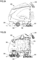
- FIGS. 2A and 2B show a first embodiment of a cleaning machine.
- machine 200 is implemented as a walk-behind scrubber drier having a cleaning unit 230 , a suction unit/squeegee 232 , a drive unit 236 , and a handle 234 .
- the operator walks behind machine 200 at approximately walking speed (e.g. 5 km/h) and directs machine 200 across the surfaces to be cleaned by using handle 234 .
- Connector socket 402 can be arranged as shown in FIG. 2A , namely on the left side of machine 200 based on an operational moving direction.
- FIG. 2B shows further components of machine 200 , for example tanks 290 and 245 .
- FIGS. 2C and 2D show a second embodiment of a cleaning machine.
- machine 200 is implemented as a ride-on scrubber drier having a cleaning unit 230 , a suction unit/squeegee 232 , a drive unit 236 , a steering wheel 234 , and pedals 235 .
- the operator sits on machine 200 , which can move at slightly above walking speed (e.g. approximately 7 km/h), and directs machine 200 across the surfaces to be cleaned by using steering wheel 234 and pedals 235 .
- Connector socket 402 can be arranged as shown in FIG. 2C , namely on the left side of machine 200 based on an operational moving direction.
- FIG. 2D shows further components of machine 200 , for example tanks 290 and 245 , battery 222 .
- machine 200 can further include an onboard charging unit 220 .
- tanks 290 and 245 are implemented in a combined tank using a flexible side wall. This concept can be used with many different types of machines and is based on a flexible tank that adapts to its respective used capacity.
- fresh solution tank 290 is made from a flexible material that allows for deformation of the walls of the tank.
- tank 290 is substantially full of fresh cleaning solution
- tank 245 which is shaped to correspond to the dimensions of tank 290 if fully occupied and which is made from a rigid material, is substantially empty.
- cleaning solution is removed from tank 290 , used during cleaning, and collected again by suction unit/squeegee 232 , it is collected as used cleaning solution in tank 245 .
- space previously occupied in tank 290 by fresh cleaning solution is made available by corresponding shifting of the flexible walls of tank 290 .
- space is made available for used cleaning solution in tank 245 .
- tanks 290 and 245 as separate rigid tanks or combined tanks does not impact the general operation of machine 200 .
- both separate and combined tanks have inherent advantages and disadvantages.
- Combined tanks typically save a substantial amount of space and allow for bigger capacities than separate rigid tanks in a vehicle of the same size.
- separate rigid tanks can be drained and filled at substantially the same time, because their capacity and/or cleaning is independent from the other.
- Service station 300 and the processes associated therewith are substantially independent from the particular type of machine used, provided that similar service processes are performed (e.g. draining/filling of liquids, charging, etc.).
- the machines 200 can further include a cleaning unit and a suction unit.
- a machine 200 typically has at least a service mode in which the machine is configured to receive/discharge supplies from and to a service station 300 and an operating mode in which the machine is configured to operate on stored supplies.
- the cleaning unit is connected to a feeding conduit and the suction unit is connected to a suction conduit.
- the feeding conduit is configured to convey cleaning liquid from tank 290 to the cleaning unit.
- the cleaning unit is configured to act on a section of a floor surface using the cleaning liquid.
- the suction unit is configured to acquire cleaning liquid used by the cleaning unit from the floor surface and to convey the used cleaning liquid through the suction conduit and into the tank 245 .
- FIG. 3A shows a system including a service station and the cleaning machine shown in FIGS. 2A and 2B .
- Machine 200 is of a ride-on type and is shown in a service arrangement, positioned on a trough 340 and ready for connection to service station 300 via service assembly 400 .
- Machine 200 is placed on grid 347 of trough 340 , which allows for disposal of used cleaning solution and rinsing/cleaning liquids.
- Service station 300 is shown having an external tank 390 x connected to service station 300 via line 391 x . Further, machine 200 can be connected to service station 300 via main supply conduit 350 .
- FIG. 3A shows an example configuration using a single service line. In other examples, machine 200 can be connected to service station 300 using more than one service line (see above).
- service station may be connected to a wired or wireless communications network for one or two-way communications with remote instruction and/or data sources.
- Such communications may permit remote collection of machine data, such as operating hours, battery capacity, fluid volumes used/dispensed, or other operating data.
- the communications network might also permit remote programming or updating of the service station 300 and/or machine 200 .
- FIG. 3A illustrates one embodiment of a wireless communications device 500 adapted to connect the service station 300 with a remote network 510 .
- the communications device 500 may be a wireless or cellular network adapter communicating on a suitable infrastructure such as 802.11x, TDMA, CDMA, or OFDMA.
- FIG. 3B shows a system including a service station and the cleaning machine shown in FIGS. 2C and 2D .
- Machine 200 is of a walk-behind type and is shown in a service arrangement, positioned on a trough 340 and ready for connection to a wall-mounted service station 300 via service assembly 400 .
- Machine 200 is placed on grid 347 , which allows for disposal of used cleaning solution and rinsing/cleaning liquids.
- Service station 300 is shown having an external tank 390 x connected to service station 300 via line 391 x . Further, machine 200 can be connected to service station 300 via main supply conduit 350 . In addition, service station 300 may be connected via a wired, physical connection 504 to a communications port 502 for communications via a network to remote computing systems.
- the physical connection 504 may include an Ethernet cable and the communications port 502 may include an RJ45 connection as is known in the art for communicating over a TCP/IP network infrastructure.
- external tanks 390 x are optional and can be replaced by corresponding connections to building water pipes. However, for reasons of efficiency, such water pipes should be of sufficient dimensions in order to allow quick filling of machine tanks (e.g. tank 290 ).
- FIG. 4 shows a schematic overview of a connector plug and socket configured to connect a service station and a cleaning machine.
- service assembly 400 comprises a connector plug 401 and a connector socket 402 .
- Service assembly 400 is configured to provide electrical and fluid connection in one single connector.
- FIG. 4 shows an example configuration based on the use of a single service line and a single connector. In other examples, the connection between a service station 300 and a machine 200 can be established using more than one service line and connector plug/socket (see above).
- Line 304 is an electrical line, which is connected via connectors 304 c and 204 c to line 204 .
- Line 304 can consist of one or several electrical leads (e.g. Vcc, Data ⁇ , Data+, and GND of a USB connection, or V+, CAN-low, CAN-high, and GND of a CAN bus connection) depending upon the electrical connection used.
- Line 304 is configured to provide data communication between control unit 310 and data exchange device (if present) and machine control unit 210 . Data communication can be provided using any known wired or wireless communication standard (e.g. Bluetooth, WiFi, USB, CAN bus, RS-232, etc.).
- wired and wireless communications can be employed in a single embodiment, for example when initiating wireless communications via a wired connection, in order to ensure that the correct components communicate with one another.
- Data communication via lines 304 , 204 can be used for initiating a wireless communication or for bulk data transfer.
- Lines 305 and 306 are fluid lines, respectively connected via connectors 305 c / 205 c and 306 c / 206 c to lines 205 and 306 .
- Lines 305 / 205 and 306 / 206 are configured to supply liquids to machine 200 .
- Line 305 / 205 is shown as having a larger diameter than line 306 / 206 due to the different purpose. While line 305 / 205 is configured to provide a high volume of fresh cleaning solution to tank 290 , line 306 / 206 is configured to provide a high pressure rinsing/cleaning solution to tank 245 .
- Line 305 and/or 306 can respectively include a supply fluid flow controller (e.g. an occlusive pump or a valve; not shown) configured to selectively prevent fluid flow through the respective line.
- the supply fluid flow controller can be integrated into the respective connector 305 c and/or 306 c (e.g. a control valve integrated into the connector, the valve optionally preventing the fluid flow whenever the connector is not connected to a corresponding socket).
- line 205 and/or 206 can respectively include a service fluid flow controller (e.g.
- the supply fluid flow controller can be integrated into the respective socket 205 c and/or 206 c (e.g. a control valve integrated into the socket, the valve optionally preventing the fluid flow whenever the socket is not connected to a corresponding connector).
- fluid flow is prevented by respective fluid flow controllers, thereby preventing any likelihood that (residual) fluid flows from any of the connectors and/or sockets when no connection is established.
- Lines 307 / 207 are electrical lines configured to provide a charging current to batteries 222 , based on a corresponding charging profile.
- Connectors 307 c and 207 c can be implemented using any suitable connector known in the art (e.g. high power connectors or similar) as long as a maximum charging current can be sustained. Further requirements can apply, for example that fluid lines are connected only when a proper connection between electrical lines has been ensured. Similarly, the electrical connections might be established only after proper, leak-proof connections of the fluid lines are ensured.
- Service assembly 400 is further designed to allow for several safety functions. For example, an operator should not be able to incorrectly connect connector plug 401 and connector socket 402 . This can be achieved, for example, using a latch-type mechanism, which prevents maintaining an incorrect connection.
- connector plug 401 must be placed in correspondence of connector socket 402 and, subsequently, a rotatory latching movement must be exerted upon connector plug 401 . If this latching movement is not completed or missed, then connector plug 401 mechanically separates from connector socket 402 upon release by the operator. Only upon correct latching of connector plug 401 , the connection is maintained when connector plug 401 is let go by the operator.
- the connector plug 401 and connector socket 402 may include keying features for proper orientation and mating of the plug 401 and socket 402 .
- Suitable actuators may be configured to prevent an unlocking movement of a connector with respect to a corresponding socket, for example a rotatory movement, a sliding movement, or a shifting movement. These and similar movements can be prevented by an actuator moving a pin into a corresponding slot and enabled by the actuator retracting the pin from the slot.
- the service assembly 400 includes a pin and sleeve connector in which the sleeve can be coupled and fastened to a corresponding structure (e.g. a tread) of a corresponding socket in a rotatory manner. Uncoupling can, in these embodiments, be prevented by keeping the sleeve from rotating using, for example, a pin and slot. If the service assembly comprises two or more separate connection lines having separate connector/socket pairs, each connector/socket pair can include a separate locking mechanism. For clarity, the schematic illustration of FIG. 4 does not show a locking mechanism.
- FIGS. 5A and 5B show an embodiment where electrical and liquid/fluid connections are separated into two connection lines and corresponding two connector plugs.
- the functionalities of connectors 401 e and 401 f and lines 350 e and 350 f as shown in FIGS. 5A and 5B essentially correspond to those of connector 401 as shown in FIGS. 4 and 5 .
- line 350 e combines electrical lines and includes lines 304 and 307 .
- connector 401 e includes connectors 304 c and 307 c in order to provide an electrical connection between service station 300 and machine 200 .
- FIG. 5A shows an embodiment where electrical and liquid/fluid connections are separated into two connection lines and corresponding two connector plugs.
- the functionalities of connectors 401 e and 401 f and lines 350 e and 350 f as shown in FIGS. 5A and 5B essentially correspond to those of connector 401 as shown in FIGS. 4 and 5 .
- line 350 e combines electrical lines and includes lines 304 and 307
- line 350 f combines liquid and/or fluid lines and includes lines 305 and 306 .
- Connector 401 f includes connectors 305 c and 306 c in order to provide a liquid and/or fluid connection between service station 300 and machine 200 . It is understood that the individual implementation of lines 350 , 350 e , and 350 f in combination with corresponding connectors 401 , 401 e , and 401 f , is of secondary importance.
- the connection between service station 300 and machine 200 can be established using a single line 350 and connector 401 , using two separate lines 350 e and 350 f as well as connectors 401 e and 401 f , or any other combination of electrical and/or fluid lines as required by the respective application.
- service station 300 With respect to the interaction between service station 300 and a machine to be serviced 200 , general safety precautions apply and are controlled by service station 300 . Additionally, mechanical elements can be built into all connectors and connection components. Further, control unit 310 of service station 300 controls activation of service functions. One key criteria during service of any kind is that the machine must remain stationary and connected during the entire service. A connection between a machine 200 and a service station 300 can only be established when the latter is powered and operational. In some embodiments, a mechanical lock or multiple locks controlled by control unit 310 can prevent connection of a machine 200 when service station 300 is not operational. The lock or locks can be configured to automatically (e.g.
- control unit 310 Upon connection of a machine 200 , an operator can select one of several service processes (e.g. refilling, service, maintenance; see below). Before or upon selection of a process, control unit 310 either checks that the connection or connections are in place or controls the mechanical lock or locks in order to prevent disconnection of machine 200 from service station 300 .
- the machine control unit 210 may generate a signal indicative of the connection or connections being in place.
- fluid/liquid connectors can only be connected after electrical connectors have been connected. In embodiments having only a single connection line and connector, this can be achieved, for example, using a specific geometry of a combined plug and socket assembly.
- electrical or mechanical means can be employed. Similarly, the electrical connector cannot be disconnected as long as fluid/liquid connectors remain connected.
- several connection lines and corresponding connectors may be connected in a specific predetermined sequence. In these embodiments, several lock mechanisms can be activated or deactivated depending upon whether specific connections have been established or disconnected (e.g. connection electrical lines before connecting fluid lines).
- connection of machine 200 to service station 300 it is ensured that no manual activation of machine functions, for example using a machine control panel, can occur. This can be achieved, for example, by disabling the machine control panel 212 upon connection of machine 200 to service station 300 . As long a particular selected process is performed by service station 300 , disconnection of machine 200 is prevented, for example using the above-described locking mechanisms. In some embodiments, where disconnection is not actively prevented, a check for the connection or connections being place can be performed continuously throughout the selected process and the process can be interrupted or stopped (e.g. aborted) upon removal of one or more connections. A process can also be aborted based on operator interaction.
- control unit 310 of service station 300 performs the selected process until it is finished.
- An operator can abort a running process by selecting a particular function via user interface 312 of service station 300 or by activating a dedicated emergency-stop element (e.g. a mechanical switch prominently placed on or in the vicinity of service station 300 .
- a dedicated emergency-stop element e.g. a mechanical switch prominently placed on or in the vicinity of service station 300 .
- control unit 310 prepares machine 200 and service station 300 for disconnection (e.g. releasing pressure and/or excess liquids in fluid/liquid lines, removing charging current from components) and deactivates the mechanical lock or locks on the connector(s).
- disconnection e.g. releasing pressure and/or excess liquids in fluid/liquid lines, removing charging current from components
- mechanical measures e.g.
- check valves for fluid connections can be provided for potential disconnection of a connector during an ongoing process. Disconnection is performed in accordance with the respective protocol (e.g. disconnection of fluid/liquid connectors first, and subsequently disconnection of electrical connectors or vice-versa), if the connections are controlled by the service station 300 .
- machine control panel 212 is enabled. This can be controlled by the control unit of the service station being configured to send a corresponding control signal to the machine control unit (e.g. wirelessly) or by the machine control unit being configured to monitor the connection and detecting a removal of the connection. Upon removal of the connection or upon receiving of the corresponding control signal, the machine control unit re-enables the machine user interface.
- FIG. 6 shows a flow chart illustrating a general operating process of the service station allowing the execution of a number of different service processes.
- process 600 starts and ends when service station 300 is switched on (e.g. put in standby mode, ready for service) and switched off (e.g. leaving standby mode, temporarily shutting down the service station), respectively.
- service station 300 is in standby mode, either awaiting connection of a machine 200 or awaiting to be switched off.
- step 603 a proper connection to machine 200 is checked. Only if a proper connection can be detected (e.g. requiring a service assembly 400 to be connected and/or the connector being latched), then service station 300 can proceed to step 604 .
- service station 300 locks service assembly 400 in order to prevent (unintentional) removal of the connection between service station 300 and machine 200 while service or maintenance is in progress.
- machine control panel 212 is disabled, in order to prevent any user interference via machine control panel 212 .
- One key issue is that machine 200 remains stationary and cannot be moved by a user either intentionally or unintentionally, as long as machine 200 is connected to service station 300 . Disabling machine control panel 212 effectively prevents any user interference via machine control panel 212 .
- Machine control panel 212 is only disabled after a specific series of steps, which ensure that service/maintenance has been completed (or aborted in a controlled manner) and that the connection has been removed (see steps 610 to 615 below).
- service station 300 provides a number of possible service programs based on the type and status of the particular machine 200 connected.
- Step 605 m denotes that service station 300 reads the corresponding data from machine 200 (e.g. by retrieving data stored in data exchange device 1000 ) or otherwise acquires the information.
- the machine type can be input by a user via a user interface 312 integrated into service station 300 .
- an operator can select a program corresponding to the desired service or maintenance to be performed and in line with the requirements of machine 200 .
- Steps 605 m and 605 u are input steps allowing a user to provide operating parameters to service station 300 .
- step 606 service station may perform an integrity check whether the type of machine 200 and the status of machine 200 are within the requirements of the selected service program.
- This step is optional since in preferred embodiments service station 300 only provides a selection of service/maintenance programs that are suitable for machine 200 currently connected and, thus, prevents at an early stage any conflicting input or selection made by a user. If any inconsistencies are determined or if any service parameters are not within operational limits, service station 300 prompts the user in step 606 o to make changes to the selection or to cancel the request. If the type of machine 200 and the status of machine 200 are compatible with the selected service program, service station 300 proceeds to run the selected service program.
- step 607 service station 300 runs the program corresponding to the selected service process. Particular examples of these processes are described further below with respect to FIGS. 7 to 9 . While the program corresponding to the selected service process is run, service station 300 periodically checks a potential error status in step 608 and—if necessary—terminates the program prematurely. Such error status can include, but is not limited to: battery failure, charging unit failure, leakage detection, pump malfunction, blockage of a line, severing of data communication, etc. If an error occurs, service station 300 enters an error handling routine, depending upon the type of error occurred. Otherwise, the program is run until the service process in finished in step 609 . It is understood that the error handling routine can include one or more steps corresponding to steps 610 to 615 in order to sever a connection between service station 300 and machine 200 in a controlled manner.
- machine control panel 212 Upon disconnection of connector 401 , machine control panel 212 is enabled again in step 614 . A corresponding output and/or report can optionally be provided in step 615 . After steps 608 e and/or 614 / 615 service station 300 returns to standby mode in step 602 .
- step 604 b the corresponding socket for receiving connector 401 f is enabled or unlocked, thereby preventing any connection of fluid/liquid connector 401 f prior to connection of electrical connector 401 e and prior to disabling machine control panel 212 .
- step 604 c service station 300 checks whether fluid/liquid connector 401 f is connected and/or latched. Optionally, the connection can be aborted in step 604 d , upon which the process continues at step 612 f of FIG. 6B . Otherwise, if the fluid/liquid connector 401 f is connected and/or latched, the process continues at step 605 in FIG. 6 .
- Step 612 f in FIG. 6B starts after preparation of disconnection in step 610 in FIG. 6 , if the connections are controlled by the service station 300 .
- service station 300 unlocks fluid/liquid connector 401 f , so that an operator can remove the connector from the corresponding socket.
- step 613 f service station 300 checks whether the fluid/liquid connection has been severed, i.e. that connector 401 f has been removed. If this cannot be determined, then service station 300 provides a corresponding output or signal in step 613 fo in order to prompt the operator or user to remove connector 401 f .
- step 612 e As soon as the fluid/liquid connection is severed, service station 300 unlocks electrical connector 401 e in step 612 e , so that an operator can remove the connector from the corresponding socket.
- step 613 e service station 300 checks whether the electrical connection has been severed, i.e. that connector 401 e has been removed. If this cannot be determined, then service station 300 provides a corresponding output or signal in step 613 eo in order to prompt the operator or user to remove connector 401 e . Once electrical connector 401 e has been disconnected, the process continues at step 614 in FIG. 6 . It is noted that, analogous to FIGS.
- FIG. 7 shows a flow chart illustrating a process for refilling a cleaning machine.
- process 700 starts.
- an output indicating the selected service process is displayed (e.g. “Refilling in progress . . . ”).
- the machine control panel 212 has already been disabled upon connection of service assembly 400 , in order to prevent any interference with the service process by a user via the machine control panel 212 (see process 600 above).
- service station 300 more specifically control unit 310 of service station 300 , obtains control over machine control unit 210 and is configured to control individual components of machine 200 , for example, valves 291 v or 296 v.
- step 706 the used solution tank 245 is drained.
- valve 296 v is actuated in order to allow for the solution present in tank 245 to drain into trough 340 .
- the draining progress is either detected using a corresponding sensor indicative of the liquid level present in tank 245 . Alternatively, the progress is based on the time necessary to empty a full tank.
- pump 362 After detecting that tank 245 has been emptied, or upon expiry of a time limit, pump 362 is controlled to supply high pressure rinsing/cleaning solution in step 708 order to facilitate flushing and/or cleaning of nozzles in used solution tank 245 .
- This rinsing and/or cleaning can be performed for a predetermined period of time, in a single cycle or in several cycles steered by valves (not shown), depending, for example, upon machine type and/or tank size.
- valve 296 v closes, optionally after a predetermined delay.
- a predetermined amount of a chemical component e.g. detergent, cleaning agent
- a chemical component e.g. detergent, cleaning agent
- FIG. 8 shows a flow chart illustrating a maintenance process for a cleaning machine.
- process 800 starts.
- an output indicating the selected service process is displayed (e.g. “Maintenance in progress . . . ”). It is noted that the machine control panel has already been disabled upon connection of service assembly 400 , in order to prevent any interference with the service process by a user via the machine control panel 212 .
- cleaning solution tank 290 is filled.
- filling of tank 290 can be performed in parallel (if machine 200 is provided with separate independent tanks) or sequentially (if machine 200 is provided with combined tanks).
- draining and re-filling can be done with a suitable overlap (i.e. filling starts before draining/rinsing ends), in order to reduce service time.
- Filling automatically stops when cleaning solution tank 290 is full. This is either controlled by a float-operated valve or by electrically operated valve controlled by service station 300 based on a corresponding sensor signal.
- FIG. 9 shows a flow chart illustrating a process for servicing a cleaning machine. This process is used if a full machine service is to be performed or if the machine is decommissioned for an extended period of time (e.g. several days or longer).
- process 900 starts.
- an output indicating the selected service process is displayed (e.g. “Service in progress . . . ”).
- power supply to the machine control unit is cut, if this has not already been done upon locking of service assembly 400 (see process 600 above).
- step 908 the used solution tank 245 is drained.
- valve 296 v is actuated in order to allow for the solution present in tank 245 to drain into trough 340 .
- the draining progress is either detected using a corresponding sensor indicative of the liquid level present in tank 245 . Alternatively, the progress based on the time necessary to empty a full tank.
- pump 362 After detecting that tank 245 has been emptied, or upon expiry of a time limit, pump 362 is controlled to supply high pressure rinsing/cleaning solution in step 910 order to facilitate flushing and/or cleaning with nozzles or other suitable means installed in used solution tank 245 .
- This rinsing and/or cleaning is performed for a predetermined period of time, in a single cycle or in several cycles steered by valves (not shown), depending, for example, upon machine type and/or tank size (see above).
- valve 296 v closes, optionally after a predetermined delay.
- step 914 cleaning solution tank 290 is emptied.
- residual liquid is drained from solution tank 290 in order to be able to perform a more extensive rinsing, cleaning, and de-scaling process of tank 290 .
- tank 290 is emptied completely.
- the cleaning and/or de-scaling agent is then left to react within tank 290 in a cleaning/de-scaling process.
- several repetitions of draining and re-filling tank 290 using corresponding solutions may be necessary.
- Performing and/or repeating any of these steps is done in step 920 .
- the descaling process might include a predetermined time of activation of pump(s) and/or valve(s) in the machine in order to reach all areas of the water system (see further details below).
- control unit 310 may, if required, activate the charging process (see above) and/or further monitor the status of battery 222 while charging. In some embodiments charging is prevented if battery 222 is substantially fully charged, for example holding 95% or more of the maximum charge. In the embodiment having more than one service line and connector, first the fluid line and connector may have to be disconnected. Subsequently, if the service station 300 controls the connection or connections, the lock on the electrical line and connector is released, enabling disconnection thereof. Process 900 ends at step 926 .
- service station 300 can be programmed with several parameters characterizing the installation site. These parameters include, for example, water hardness.
- Control unit 300 is configured to compute several service parameters using the installation site parameters. For example, based on water hardness and machine type, corresponding de-scaling schedules can be determined. Hard water can lead to premature malfunctions or other failures, for example relating to pumps, valves, and nozzles, if de-scaling is not done in prescribed intervals according to the water hardness.
- Manual scheduling of de-scaling can be done in several ways. The most basic process is merely based on instructions listed in the user manual of a machine 200 , detailing to operators at which intervals, depending on water hardness in the region, de-scaling is to be performed. There are no mechanisms in place to confirm that the respective schedule is being followed, or to determine that a de-scaling process has been performed correctly.
- installation site parameters can be programmed into the machine control unit 210 , which can calculate, based on operating parameters (e.g. operating hours, amounts of liquid processed, etc.), when de-scaling is necessary.
- a suitable indicator e.g. warning light
- control unit 210 can be activated once control unit 210 has determined that de-scaling is to be performed. Again, there are no mechanisms in place to confirm that the respective schedule is being followed, or to determine that a de-scaling process has been performed correctly.
- the date and number of de-scaling processed performed can be tracked and stored in a memory component (e.g. in machine control unit 210 and/or in data exchange device 1000 ).
- de-scaling scenarios require user interaction, for example activation of de-scaling by means of pressing a combination of switches on an operating panel of machine 200 or by means of selecting and/or activating a software program.
- the steps are either manually executed or performed by machine control unit 200 based on stored information.
- the steps can include the following.
- the exact amount depends upon the size of tank 290 , the water supply system, and/or other factors.
- Adding a predetermined dose of acid e.g. phosphoric acid
- a predetermined dose of acid e.g. phosphoric acid
- Activating water flow in machine 200 in order to distribute the water/acid solution into the system and to all components (e.g. valves, couplings, lines, nozzles). Stopping water flow in order to let de-scaling take place. Activating water flow again in order to rinse lime scale and other particles, and to move fresh water/acid solution to the components. If necessary, repeat the previous steps until all water/acid solution has been used up.
- Refill tank 290 with clear water for rinsing the system. Activate water flow until all water/acid solution is rinsed from system (e.g. exiting at tools couplings, drains, etc.). Confirming end of rinsing and end of de-scaling process.
- the discharging scheme is managed by machine control unit 210 .
- Machine control unit 210 be programmed or equipped with several discharging schemes. On delivery of machine 200 , a general or default scheme is activated. Changes to the schemes have to be programmed on-site, for example by service personnel using a portable computer, a service data connection to the machine, and a corresponding service application running on the portable computer.
- Wrong or incorrect battery management can have detrimental effects on battery life, capacity, and/or performance, and a mechanism addressing the above problems is required.
- a simple approach would be having the machine control and/or power units monitor and record at least the number of charging cycles and the charging time, as it is also connected to the batteries.
- Such an approach can be in conflict with local regulations (e.g. EU regulations on the use of charging system in such machines). Such regulations may request that during charging electrical power to the machine must be interrupted or—when using flooded batteries or lead-acid batteries—all poles must be disconnected. Monitoring or control of the charging process by the machine control unit 210 , therefore, becomes impossible.
Landscapes
- Cleaning In General (AREA)
Abstract
Description
Claims (20)
Priority Applications (1)
| Application Number | Priority Date | Filing Date | Title |
|---|---|---|---|
| US16/081,521 US11147425B2 (en) | 2016-03-03 | 2017-03-03 | Service system |
Applications Claiming Priority (3)
| Application Number | Priority Date | Filing Date | Title |
|---|---|---|---|
| US201662302844P | 2016-03-03 | 2016-03-03 | |
| PCT/EP2017/055001 WO2017149116A1 (en) | 2016-03-03 | 2017-03-03 | Service system |
| US16/081,521 US11147425B2 (en) | 2016-03-03 | 2017-03-03 | Service system |
Publications (2)
| Publication Number | Publication Date |
|---|---|
| US20210177228A1 US20210177228A1 (en) | 2021-06-17 |
| US11147425B2 true US11147425B2 (en) | 2021-10-19 |
Family
ID=58277257
Family Applications (1)
| Application Number | Title | Priority Date | Filing Date |
|---|---|---|---|
| US16/081,521 Active 2038-12-12 US11147425B2 (en) | 2016-03-03 | 2017-03-03 | Service system |
Country Status (6)
| Country | Link |
|---|---|
| US (1) | US11147425B2 (en) |
| EP (1) | EP3422920B1 (en) |
| CN (1) | CN108697294B (en) |
| AU (1) | AU2017226954B2 (en) |
| CA (1) | CA3015115A1 (en) |
| WO (1) | WO2017149116A1 (en) |
Cited By (2)
| Publication number | Priority date | Publication date | Assignee | Title |
|---|---|---|---|---|
| US20230051316A1 (en) * | 2021-08-11 | 2023-02-16 | Hyundai Motor Company | Fluid supply system of docking station for moving device and method for controlling same |
| US12189395B2 (en) | 2021-08-11 | 2025-01-07 | Hyundai Motor Company | Autonomous mobile apparatus, docking station, and method of controlling same apparatus |
Families Citing this family (5)
| Publication number | Priority date | Publication date | Assignee | Title |
|---|---|---|---|---|
| JP7516002B2 (en) * | 2018-09-04 | 2024-07-16 | 東芝ライフスタイル株式会社 | Electric Vacuum Equipment |
| US11266286B2 (en) * | 2018-10-18 | 2022-03-08 | FutureGenTechnologies Inc. | Floor cleaning robot and docking station therefore |
| EP3911212B1 (en) | 2019-01-18 | 2023-03-29 | Alfred Kärcher SE & Co. KG | Floor cleaning device |
| JP2020150787A (en) * | 2019-02-28 | 2020-09-17 | ソーラーエッジ テクノロジーズ リミテッド | Relay array for grid connection |
| CN115474875B (en) * | 2021-06-16 | 2024-05-24 | 苏州瑞久智能科技有限公司 | Floor cleaning system |
Citations (15)
| Publication number | Priority date | Publication date | Assignee | Title |
|---|---|---|---|---|
| DE4230197A1 (en) | 1992-09-09 | 1994-03-10 | Kurt Zachhuber | Storage and maintenance facility |
| US5890258A (en) | 1997-04-03 | 1999-04-06 | Lee; Kyu H. | Carpet cleaner with pull-out tray support for service and repair of components |
| US6105203A (en) | 1998-04-22 | 2000-08-22 | Diversey Lever, Inc. | Floor cleaning machine |
| TW511292B (en) | 2000-10-27 | 2002-11-21 | Matsushita Electric Industrial Co Ltd | Display device |
| DE10142192C1 (en) | 2001-08-29 | 2003-03-20 | Hako Gmbh | Mobile machine for cleaning floor incorporates cleaning tool, container for cleaning fluid, dirty liquid container, and suction device with receptacle for used cleaning fluid and fan |
| CN201572046U (en) | 2009-11-17 | 2010-09-08 | 大连大学 | A ground water absorbing device |
| US20120000021A1 (en) * | 2009-03-17 | 2012-01-05 | Nilfisk-Advance S.P.A. | Surface-cleaning machine with on-board operator |
| US20130095246A1 (en) * | 2011-10-18 | 2013-04-18 | Minuteman International, Inc. | Floor treatment procedure |
| US20130193041A1 (en) | 2008-02-14 | 2013-08-01 | Baxter Healthcare S.A. | Control of a water device via a dialysis machine user interface |
| CN103685451A (en) | 2012-09-06 | 2014-03-26 | Lg电子株式会社 | Household appliances and online systems including the same |
| US20140130292A1 (en) * | 2003-05-14 | 2014-05-15 | Kärcher North America, Inc. | Floor cleaning apparatus |
| US20140157533A1 (en) | 2010-04-29 | 2014-06-12 | Diversey, Inc. | Floor cleaning tool and method |
| US20150014228A1 (en) | 2013-03-21 | 2015-01-15 | Seven Hour Drive, LLC | Auxiliary gray water source device for commercial kitchens |
| US20150265123A1 (en) * | 2014-03-24 | 2015-09-24 | Nai Pong Simon Chen | Floor Cleaning Machines Having Intelligent Systems, Associated Sub-Assemblies Incorporating Intelligent Systems, and Associated Methods of Use |
| US20160037983A1 (en) * | 2014-08-06 | 2016-02-11 | Vorwerk & Co. Interholding Gmbh | Floor cleaning device for dry and wet cleaning as well as method for operating a self-propelled floor cleaning device |
Family Cites Families (1)
| Publication number | Priority date | Publication date | Assignee | Title |
|---|---|---|---|---|
| TWM511292U (en) * | 2015-06-16 | 2015-11-01 | Ya-Jing Yang | Rotational-type mop structure |
-
2017
- 2017-03-03 US US16/081,521 patent/US11147425B2/en active Active
- 2017-03-03 EP EP17710680.4A patent/EP3422920B1/en active Active
- 2017-03-03 WO PCT/EP2017/055001 patent/WO2017149116A1/en not_active Ceased
- 2017-03-03 CA CA3015115A patent/CA3015115A1/en active Pending
- 2017-03-03 CN CN201780014647.1A patent/CN108697294B/en active Active
- 2017-03-03 AU AU2017226954A patent/AU2017226954B2/en active Active
Patent Citations (16)
| Publication number | Priority date | Publication date | Assignee | Title |
|---|---|---|---|---|
| US5572759A (en) | 1992-09-09 | 1996-11-12 | Zachhuber; Kurt | Storage and maintenance system |
| DE4230197A1 (en) | 1992-09-09 | 1994-03-10 | Kurt Zachhuber | Storage and maintenance facility |
| US5890258A (en) | 1997-04-03 | 1999-04-06 | Lee; Kyu H. | Carpet cleaner with pull-out tray support for service and repair of components |
| US6105203A (en) | 1998-04-22 | 2000-08-22 | Diversey Lever, Inc. | Floor cleaning machine |
| TW511292B (en) | 2000-10-27 | 2002-11-21 | Matsushita Electric Industrial Co Ltd | Display device |
| DE10142192C1 (en) | 2001-08-29 | 2003-03-20 | Hako Gmbh | Mobile machine for cleaning floor incorporates cleaning tool, container for cleaning fluid, dirty liquid container, and suction device with receptacle for used cleaning fluid and fan |
| US20140130292A1 (en) * | 2003-05-14 | 2014-05-15 | Kärcher North America, Inc. | Floor cleaning apparatus |
| US20130193041A1 (en) | 2008-02-14 | 2013-08-01 | Baxter Healthcare S.A. | Control of a water device via a dialysis machine user interface |
| US20120000021A1 (en) * | 2009-03-17 | 2012-01-05 | Nilfisk-Advance S.P.A. | Surface-cleaning machine with on-board operator |
| CN201572046U (en) | 2009-11-17 | 2010-09-08 | 大连大学 | A ground water absorbing device |
| US20140157533A1 (en) | 2010-04-29 | 2014-06-12 | Diversey, Inc. | Floor cleaning tool and method |
| US20130095246A1 (en) * | 2011-10-18 | 2013-04-18 | Minuteman International, Inc. | Floor treatment procedure |
| CN103685451A (en) | 2012-09-06 | 2014-03-26 | Lg电子株式会社 | Household appliances and online systems including the same |
| US20150014228A1 (en) | 2013-03-21 | 2015-01-15 | Seven Hour Drive, LLC | Auxiliary gray water source device for commercial kitchens |
| US20150265123A1 (en) * | 2014-03-24 | 2015-09-24 | Nai Pong Simon Chen | Floor Cleaning Machines Having Intelligent Systems, Associated Sub-Assemblies Incorporating Intelligent Systems, and Associated Methods of Use |
| US20160037983A1 (en) * | 2014-08-06 | 2016-02-11 | Vorwerk & Co. Interholding Gmbh | Floor cleaning device for dry and wet cleaning as well as method for operating a self-propelled floor cleaning device |
Non-Patent Citations (2)
| Title |
|---|
| International Search Report and Written Opinion of International Application No. PCT/EP2017/055001 dated May 29, 2017. |
| Office Action of counterpart Chinese Patent Application No. 201780014647.1 dated Jun. 11, 2020; 7 pages. |
Cited By (3)
| Publication number | Priority date | Publication date | Assignee | Title |
|---|---|---|---|---|
| US20230051316A1 (en) * | 2021-08-11 | 2023-02-16 | Hyundai Motor Company | Fluid supply system of docking station for moving device and method for controlling same |
| US12161276B2 (en) * | 2021-08-11 | 2024-12-10 | Hyundai Motor Company | Fluid supply system of docking station for moving device and method for controlling same |
| US12189395B2 (en) | 2021-08-11 | 2025-01-07 | Hyundai Motor Company | Autonomous mobile apparatus, docking station, and method of controlling same apparatus |
Also Published As
| Publication number | Publication date |
|---|---|
| EP3422920A1 (en) | 2019-01-09 |
| AU2017226954A1 (en) | 2018-09-20 |
| CA3015115A1 (en) | 2017-09-08 |
| CN108697294A (en) | 2018-10-23 |
| AU2017226954B2 (en) | 2022-02-24 |
| US20210177228A1 (en) | 2021-06-17 |
| EP3422920B1 (en) | 2022-05-04 |
| WO2017149116A1 (en) | 2017-09-08 |
| CN108697294B (en) | 2021-04-30 |
Similar Documents
| Publication | Publication Date | Title |
|---|---|---|
| US11147425B2 (en) | Service system | |
| CN109068925B (en) | Floor cleaning system | |
| CN113243843B (en) | Cleaning, drying and disinfection method for base station, surface cleaning system and surface cleaning equipment | |
| KR101397056B1 (en) | Robot cleaner system and control method thereof | |
| CN113243850A (en) | Communication method for base station and surface cleaning equipment and storage medium | |
| WO2023065902A1 (en) | Cleaning apparatus and cleaning system | |
| CN112220416B (en) | Liquid supply system, control method of liquid supply system and cleaning robot | |
| CN109068926B (en) | Floor treatment system and method for operating the same | |
| US10829388B1 (en) | Valve control apparatus | |
| CN114431796A (en) | Cleaning equipment base station, cleaning equipment and cleaning equipment system | |
| CN214632017U (en) | Surface cleaning device, base station, surface cleaning system and control device | |
| CN214965146U (en) | Surface cleaning equipment, base station, surface cleaning system and control device | |
| CN113243842A (en) | Surface cleaning device, base station, surface cleaning system and control method | |
| US20210159657A1 (en) | Supply device from supplying a mobile device with a material and mobile device | |
| US20250228420A1 (en) | Cleaning apparatus and control method thereof, device, base station, system, and storage medium | |
| WO2022171023A1 (en) | Base station for surface cleaning apparatus, and surface cleaning system and control method | |
| CN109577425A (en) | Leak-proof device and anti-leaking method, base station and base station anti-leaking method | |
| US20120111369A1 (en) | Method and installation for cleaning a spraying circuit, in particular of paint, and for treating the chemical effluents generated | |
| CN114680756B (en) | Water intake device and control method for combined cleaning equipment | |
| CN116057166A (en) | Bioreactor cleaning device for a bioreactor in a rail vehicle | |
| CN114680737A (en) | Water using system of sweeping robot | |
| KR20180021658A (en) | All-purpose equipment connected with cleaning equipment for cleaning pipes | |
| CN219613778U (en) | Cleaning systems, cleaning equipment and base stations | |
| US11203532B1 (en) | Piston valve with annular passages | |
| WO2022171022A1 (en) | Surface cleaning device, base station, surface cleaning system and control method |
Legal Events
| Date | Code | Title | Description |
|---|---|---|---|
| FEPP | Fee payment procedure |
Free format text: ENTITY STATUS SET TO UNDISCOUNTED (ORIGINAL EVENT CODE: BIG.); ENTITY STATUS OF PATENT OWNER: LARGE ENTITY |
|
| AS | Assignment |
Owner name: CREDIT SUISSE AG, CAYMAN ISLANDS BRANCH, NEW YORK Free format text: SUPPLEMENTAL SECURITY AGREEMENT;ASSIGNOR:DIVERSEY, INC.;REEL/FRAME:049364/0084 Effective date: 20190604 |
|
| STPP | Information on status: patent application and granting procedure in general |
Free format text: DOCKETED NEW CASE - READY FOR EXAMINATION |
|
| STPP | Information on status: patent application and granting procedure in general |
Free format text: NOTICE OF ALLOWANCE MAILED -- APPLICATION RECEIVED IN OFFICE OF PUBLICATIONS |
|
| STPP | Information on status: patent application and granting procedure in general |
Free format text: PUBLICATIONS -- ISSUE FEE PAYMENT VERIFIED |
|
| STCF | Information on status: patent grant |
Free format text: PATENTED CASE |
|
| AS | Assignment |
Owner name: GOLDMAN SACHS BANK USA, NEW YORK Free format text: TERM LOAN PATENT SECURITY AGREEMENT;ASSIGNORS:BIRKO CORPORATION;SOLENIS TECHNOLOGIES, L.P.;INNOVATIVE WATER CARE, LLC;AND OTHERS;REEL/FRAME:064223/0526 Effective date: 20230705 Owner name: BANK OF AMERICA, N.A., GEORGIA Free format text: ABL PATENT SECURITY AGREEMENT;ASSIGNORS:BIRKO CORPORATION;SOLENIS TECHNOLOGIES, L.P.;INNOVATIVE WATER CARE, LLC;AND OTHERS;REEL/FRAME:064222/0751 Effective date: 20230705 |
|
| AS | Assignment |
Owner name: BANK OF NEW YORK MELLON TRUST COMPANY, N.A., ILLINOIS Free format text: NOTES PATENT SECURITY AGREEMENT;ASSIGNORS:BIRKO CORPORATION;SOLENIS TECHNOLOGIES, L.P.;INNOVATIVE WATER CARE, LLC;AND OTHERS;REEL/FRAME:064348/0235 Effective date: 20230705 Owner name: BANK OF NEW YORK MELLON TRUST COMPANY, N.A., ILLINOIS Free format text: 2021 NOTES PATENT SECURITY AGREEMENT;ASSIGNORS:BIRKO CORPORATION;SOLENIS TECHNOLOGIES, L.P.;INNOVATIVE WATER CARE, LLC;AND OTHERS;REEL/FRAME:064225/0576 Effective date: 20230705 Owner name: BANK OF NEW YORK MELLON TRUST COMPANY, N.A., ILLINOIS Free format text: 2023 NOTES PATENT SECURITY AGREEMENT;ASSIGNORS:BIRKO CORPORATION;SOLENIS TECHNOLOGIES, L.P.;INNOVATIVE WATER CARE, LLC;AND OTHERS;REEL/FRAME:064225/0170 Effective date: 20230705 |
|
| AS | Assignment |
Owner name: DIVERSEY, INC., NORTH CAROLINA Free format text: RELEASE OF SECURITY AGREEMENT REEL/FRAME 049364/0084;ASSIGNOR:CREDIT SUISSE AG, CAYMAN ISLANDS BRANCH;REEL/FRAME:064236/0818 Effective date: 20230705 |
|
| AS | Assignment |
Owner name: THE BANK OF NEW YORK MELLON TRUST COMPANY, N.A., AS NOTES COLLATERAL AGENT, ILLINOIS Free format text: SECURITY AGREEMENT (2024 NOTES);ASSIGNORS:BIRKO CORPORATION;DIVERSEY, INC.;DIVERSEY TASKI, INC.;AND OTHERS;REEL/FRAME:067824/0278 Effective date: 20240621 |
|
| MAFP | Maintenance fee payment |
Free format text: PAYMENT OF MAINTENANCE FEE, 4TH YEAR, LARGE ENTITY (ORIGINAL EVENT CODE: M1551); ENTITY STATUS OF PATENT OWNER: LARGE ENTITY Year of fee payment: 4 |
|
| AS | Assignment |
Owner name: THE BANK OF NEW YORK MELLON TRUST COMPANY, N.A., AS NOTES COLLATERAL AGENT, ILLINOIS Free format text: SECURITY AGREEMENT (NOTES);ASSIGNORS:DIVERSEY, INC.;DIVERSEY TASKI, INC.;INNOVATIVE WATER CARE, LLC;AND OTHERS;REEL/FRAME:073061/0885 Effective date: 20251009 Owner name: BIRKO CORPORATION, COLORADO Free format text: RELEASE OF 2023 NOTES PATENT SECURITY INTERESTS;ASSIGNOR:THE BANK OF NEW YORK MELLON TRUST COMPANY, N.A.;REEL/FRAME:073074/0198 Effective date: 20251009 Owner name: DIVERSEY, INC., SOUTH CAROLINA Free format text: RELEASE OF 2023 NOTES PATENT SECURITY INTERESTS;ASSIGNOR:THE BANK OF NEW YORK MELLON TRUST COMPANY, N.A.;REEL/FRAME:073074/0198 Effective date: 20251009 Owner name: DIVERSEY TASKI, INC., SOUTH CAROLINA Free format text: RELEASE OF 2023 NOTES PATENT SECURITY INTERESTS;ASSIGNOR:THE BANK OF NEW YORK MELLON TRUST COMPANY, N.A.;REEL/FRAME:073074/0198 Effective date: 20251009 Owner name: INNOVATIVE WATER CARE, LLC, DELAWARE Free format text: RELEASE OF 2023 NOTES PATENT SECURITY INTERESTS;ASSIGNOR:THE BANK OF NEW YORK MELLON TRUST COMPANY, N.A.;REEL/FRAME:073074/0198 Effective date: 20251009 Owner name: SOLENIS TECHNOLOGIES, L.P., DELAWARE Free format text: RELEASE OF 2023 NOTES PATENT SECURITY INTERESTS;ASSIGNOR:THE BANK OF NEW YORK MELLON TRUST COMPANY, N.A.;REEL/FRAME:073074/0198 Effective date: 20251009 |
|
| AS | Assignment |
Owner name: BIRKO CORPORATION, COLORADO Free format text: RELEASE OF SECURITY INTEREST;ASSIGNOR:THE BANK OF NEW YORK MELLON TRUST COMPANY, N.A., AS NOTES COLLATERAL AGENT;REEL/FRAME:073564/0864 Effective date: 20251103 Owner name: DIVERSEY, INC., SOUTH CAROLINA Free format text: RELEASE OF SECURITY INTEREST;ASSIGNOR:THE BANK OF NEW YORK MELLON TRUST COMPANY, N.A., AS NOTES COLLATERAL AGENT;REEL/FRAME:073564/0864 Effective date: 20251103 Owner name: DIVERSEY TASKI, INC., SOUTH CAROLINA Free format text: RELEASE OF SECURITY INTEREST;ASSIGNOR:THE BANK OF NEW YORK MELLON TRUST COMPANY, N.A., AS NOTES COLLATERAL AGENT;REEL/FRAME:073564/0864 Effective date: 20251103 Owner name: INNOVATIVE WATER CARE, LLC, DELAWARE Free format text: RELEASE OF SECURITY INTEREST;ASSIGNOR:THE BANK OF NEW YORK MELLON TRUST COMPANY, N.A., AS NOTES COLLATERAL AGENT;REEL/FRAME:073564/0864 Effective date: 20251103 Owner name: SOLENIS TECHNOLOGIES, L.P., DELAWARE Free format text: RELEASE OF SECURITY INTEREST;ASSIGNOR:THE BANK OF NEW YORK MELLON TRUST COMPANY, N.A., AS NOTES COLLATERAL AGENT;REEL/FRAME:073564/0864 Effective date: 20251103 Owner name: THE BANK OF NEW YORK MELLON TRUST COMPANY, N.A., AS NOTES COLLATERAL AGENT, ILLINOIS Free format text: SECURITY INTEREST;ASSIGNORS:CHEM-AQUA, INC.;DIVERSEY, INC.;DIVERSEY TASKI, INC.;AND OTHERS;REEL/FRAME:073570/0838 Effective date: 20251103 |