US11144534B2 - Control device, time stamp modification method, computer program, and data structure - Google Patents
Control device, time stamp modification method, computer program, and data structure Download PDFInfo
- Publication number
- US11144534B2 US11144534B2 US15/952,378 US201815952378A US11144534B2 US 11144534 B2 US11144534 B2 US 11144534B2 US 201815952378 A US201815952378 A US 201815952378A US 11144534 B2 US11144534 B2 US 11144534B2
- Authority
- US
- United States
- Prior art keywords
- time
- time stamp
- correction processing
- data
- correction
- Prior art date
- Legal status (The legal status is an assumption and is not a legal conclusion. Google has not performed a legal analysis and makes no representation as to the accuracy of the status listed.)
- Active, expires
Links
Images


Classifications
-
- G—PHYSICS
- G05—CONTROLLING; REGULATING
- G05B—CONTROL OR REGULATING SYSTEMS IN GENERAL; FUNCTIONAL ELEMENTS OF SUCH SYSTEMS; MONITORING OR TESTING ARRANGEMENTS FOR SUCH SYSTEMS OR ELEMENTS
- G05B19/00—Program-control systems
- G05B19/02—Program-control systems electric
- G05B19/04—Program control other than numerical control, i.e. in sequence controllers or logic controllers
- G05B19/042—Program control other than numerical control, i.e. in sequence controllers or logic controllers using digital processors
- G05B19/0423—Input/output
-
- G—PHYSICS
- G06—COMPUTING OR CALCULATING; COUNTING
- G06F—ELECTRIC DIGITAL DATA PROCESSING
- G06F16/00—Information retrieval; Database structures therefor; File system structures therefor
- G06F16/20—Information retrieval; Database structures therefor; File system structures therefor of structured data, e.g. relational data
- G06F16/23—Updating
- G06F16/2365—Ensuring data consistency and integrity
-
- G—PHYSICS
- G06—COMPUTING OR CALCULATING; COUNTING
- G06F—ELECTRIC DIGITAL DATA PROCESSING
- G06F17/00—Digital computing or data processing equipment or methods, specially adapted for specific functions
- G06F17/40—Data acquisition and logging
-
- G—PHYSICS
- G06—COMPUTING OR CALCULATING; COUNTING
- G06F—ELECTRIC DIGITAL DATA PROCESSING
- G06F1/00—Details not covered by groups G06F3/00 - G06F13/00 and G06F21/00
- G06F1/04—Generating or distributing clock signals or signals derived directly therefrom
- G06F1/14—Time supervision arrangements, e.g. real time clock
-
- G—PHYSICS
- G06—COMPUTING OR CALCULATING; COUNTING
- G06F—ELECTRIC DIGITAL DATA PROCESSING
- G06F16/00—Information retrieval; Database structures therefor; File system structures therefor
- G06F16/20—Information retrieval; Database structures therefor; File system structures therefor of structured data, e.g. relational data
- G06F16/22—Indexing; Data structures therefor; Storage structures
- G06F16/2282—Tablespace storage structures; Management thereof
-
- G—PHYSICS
- G06—COMPUTING OR CALCULATING; COUNTING
- G06F—ELECTRIC DIGITAL DATA PROCESSING
- G06F16/00—Information retrieval; Database structures therefor; File system structures therefor
- G06F16/20—Information retrieval; Database structures therefor; File system structures therefor of structured data, e.g. relational data
- G06F16/24—Querying
- G06F16/245—Query processing
- G06F16/2458—Special types of queries, e.g. statistical queries, fuzzy queries or distributed queries
- G06F16/2474—Sequence data queries, e.g. querying versioned data
-
- G—PHYSICS
- G06—COMPUTING OR CALCULATING; COUNTING
- G06F—ELECTRIC DIGITAL DATA PROCESSING
- G06F16/00—Information retrieval; Database structures therefor; File system structures therefor
- G06F16/20—Information retrieval; Database structures therefor; File system structures therefor of structured data, e.g. relational data
- G06F16/24—Querying
- G06F16/245—Query processing
- G06F16/2458—Special types of queries, e.g. statistical queries, fuzzy queries or distributed queries
- G06F16/2477—Temporal data queries
-
- G—PHYSICS
- G05—CONTROLLING; REGULATING
- G05B—CONTROL OR REGULATING SYSTEMS IN GENERAL; FUNCTIONAL ELEMENTS OF SUCH SYSTEMS; MONITORING OR TESTING ARRANGEMENTS FOR SUCH SYSTEMS OR ELEMENTS
- G05B2219/00—Program-control systems
- G05B2219/20—Pc systems
- G05B2219/25—Pc structure of the system
- G05B2219/25257—Microcontroller
Definitions
- An embodiment relates to a control device applicable to FA (Factory Automation), for example.
- a PLC is a computer that has a processor and a memory and operates in accordance with a computer program.
- a study relating to programming languages for PLCs was spearheaded by IEC SC65B/WG7/TF3, and published in 1993 as the international standard IEC 61131-3. This standard prescribes “4 languages+1 element” including ladder language which has conventionally been the mainstay language, and recent PLCs have been developed in line with this standard.
- IEC 61131-3 there is a program unit called a POU (Program Organization Unit).
- a POU approximates the concept of a class in an object-oriented language, and can include one or more FBs (Function Blocks) which are the equivalent to a function or a method.
- PLCs have become highly developed, and are provided with ultra high-speed CPUs (Central Processing Units) and mass memories. It has thus become possible to implement applications that could not previously be implemented.
- Using PLCs as a database to store large amounts of data is one such example.
- a time-series database is a database optimized to be able to process queries designating a period (time range) at high speed, and have recently attracted attention in fields such as AI (Artificial Intelligence) and IoT (Internet of Things).
- AI Artificial Intelligence
- IoT Internet of Things
- a problem here is the accuracy of the time stamps between time-series data collected by a plurality of PLCs. This is because the internal clock (local clock) of a PLC drifts due to disturbances such as temperature, and the degree of drift differs for each PLC.
- JP 2015-201194A the time stamps of real-time data are normalized by a plurality of devices exchanging time information, in an effort to maintain relative time synchronization between the devices.
- issues arise such as a greater communication load and a drop in efficiency.
- synchronization between data is not guaranteed in the event of processing that integrates data across a plurality of systems (data mining).
- data mining data mining
- JP 2015-201194A is an example of background art.
- One or more aspects have been made in view of the above circumstances, and an object thereof is to provide a control device capable of acquiring data to which an accurate time stamp has been assigned, a time stamp modification method, a computer program and a data structure.
- a first aspect is configured to include a local clock configured to provide a local time serving as a basis of a time stamp, a correction unit configured to repeatedly execute correction processing of the local time, a storage unit configured to store a time correction amount for each iteration of the correction processing, a data collection unit configured to collect data related to a controlled object, a database configured to store the collected data, with the time stamp attached to the data, an extraction unit configured to extract, from the database, data corresponding to a period designated by a query directed to the database, a modification unit configured to modify the time stamp of the extracted data, based on the time correction amount, and a response unit configured to send the data with the modified time stamp attached thereto to an issuer of the query.
- a local clock configured to provide a local time serving as a basis of a time stamp
- a correction unit configured to repeatedly execute correction processing of the local time
- a storage unit configured to store a time correction amount for each iteration of the correction processing
- a data collection unit configured to collect data related to
- the time correction amount for each iteration of the correction processing of local time that is executed on a regular basis is stored in the storage unit.
- Data related to a controlled object is collected by the data collection unit, and stored with a time stamp attached in a database.
- a query directed to a database is received, data corresponding to the period designated by this query is extracted from the database.
- the time stamp of the extracted data is modified by the modification unit, based on the time correction amount.
- the data with the modified time stamp attached is then sent to the issuer of the query.
- the time stamp that is attached to the data read out from the database is thereby modified before being sent to the query source.
- deviation in the time stamp caused by error that occurs in the internal clock is modified, and, accordingly, it becomes possible to acquire data accompanied by an accurate time stamp.
- a second aspect is configured to cause the storage unit to store the time correction amount for each iteration of the correction processing in association with an identifier for identifying the iteration of the correction processing, to store a record that includes the data with the time stamp attached thereto and the identifier of the iteration of the correction processing of the local time from which the time stamp of the data derives in the database, and such that the modification unit acquires the time correction amount corresponding to the identifier included in the record that includes the extracted data, and modifies the time stamp of the extracted data, based on the acquired time correction amount.
- the time correction amount of the correction processing is stored in association with an identifier for each iteration.
- the data with a time stamp attached thereto is stored in a database as a set with the identifier of the correction processing that resulted in the local time on which the time stamp is based.
- the modification unit acquires the time correction amount with reference to the identifier of the set (record) that includes the extracted data, and modifies the time stamp based on the value of the acquired time correction amount.
- a time stamp and a reference (identifier) to a time correction amount for modifying this time stamp are stored in the database at one set.
- a third aspect is configured such that the modification unit modifies the time stamp based on a value obtained by interpolating the acquired time correction amount on a basis of a time at which the correction processing was executed.
- the time stamp is modified based on a value obtained by interpolating the corresponding time correction amount, with reference to the time at which correction processing of the local time on which the time stamp is based was executed. For example, assume that correction processing is executed at 24 hour intervals, and that the time correction amount during the interval was 0.6 msec. In this case, the time stamp attached 12 hours after the previous correction processing will be modified by 0.3 msec. Similarly, in the case of a time stamp attached 8 hours after, the modification amount will be 0.2 msec.
- time stamps are corrected with a value obtained by proportionally distributing the time correction amount by the time period that has elapsed from the previous iteration.
- the number of significant figures contributing to modification of time stamps can thereby be markedly increased, and accuracy can be dramatically improved.
- a fourth aspect is configured such that the database is a time-series database designed in preparation for responding to a query that includes designation of the period.
- the responsiveness to a query designating a time range can be enhanced, by storing data in a time-series database.
- a fifth aspect is configured such that the correction unit accesses a time server providing a global time and executes correction processing of the local time.
- time stamps can be modified on the basis of a globally unified standard, by accessing an NTP server and referring to a global time, for example.
- a sixth aspect is configured such that the data collection unit collects the data at a higher frequency than the frequency of the correction processing by the correction unit.
- an aspect can also be applied to a system in which the data collection cycle is in the order of a few msecs, for example.
- a seventh aspect is configured to further include a learning unit configured to create learning data related to accuracy of the correction processing by feedback learning that uses the time correction amount for each iteration of the correction processing, and such that the correction unit corrects the local time with reference to the created learning data.
- a learning unit configured to create learning data related to accuracy of the correction processing by feedback learning that uses the time correction amount for each iteration of the correction processing, and such that the correction unit corrects the local time with reference to the created learning data.
- learning data relating to the accuracy of past correction processing is created by the learning unit, and the local time is corrected with reference to the learning data. Accordingly, the accuracy of the internal clock itself can be improved, and the accuracy of the time stamps can therefore also be enhanced.
- An eighth aspect is configured to further include a determination unit configured to determine a validity of the correction processing of the local time, and such that the correction unit disables correction processing that is determined to not be valid by the determination unit.
- a ninth aspect is a data structure of a record that is stored in a database provided in a device having a clock, the data structure including data related to a controlled object of the device, a time stamp assigned to the data, and an identifier for identifying correction processing of a time provided by the clock.
- time correction processing is implemented on a regular basis (every hour, every 12 hours, or every 24 hours), for example, and each iteration of correction processing can be distinguished by consecutive numbers or the like.
- consecutive numbers exemplary identifiers
- a control device capable of acquiring data to which an accurate time stamp has been assigned, a time stamp modification method, a computer program and a data structure can be provided.
- FIG. 1 is a diagram illustrating an example of a control system that includes a control device according to an embodiment.
- FIG. 2 is a block diagram illustrating an example of a control system according to an embodiment.
- FIG. 3 is a block diagram illustrating an example of the hardware configuration of a computer.
- FIG. 4 is a block diagram illustrating an example of the software configuration of a computer.
- FIG. 5 is a block diagram illustrating an example of a PLC.
- FIG. 6 is a diagram illustrating an example of an NTP log.
- FIG. 7 is a diagram illustrating an example of a time-series database 102 b.
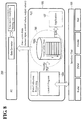
- FIG. 8 is a schematic diagram illustrating an example of dataflow between blocks according to an embodiment.
- FIG. 9 is a sequence chart illustrating an example of a processing procedure according to an embodiment.
- FIG. 10 is a diagram illustrating an example of data whose time stamps have been modified.
- FIG. 1 is a diagram showing an example of a control system that includes a control device according to an embodiment.
- the control system is installed in a base 1000 such as a factory or a distribution warehouse, for example.
- the control system is provided with a PLC 100 serving as an example of a control device and a computer (PC) 200 that is communicably connected to this PLC 100 via a LAN (Local Area Network) 3 .
- PC computer
- a computer program that includes a command for causing the PC 200 to execute a procedure or a method according to an embodiment to be installed on the PC 200 from a recording medium 30 such as a CD-ROM.
- the CD-ROM 30 is a medium capable of optically recording information such as computer programs in manner that enables a computer or another device, machine or the like to read the recorded programs or other information.
- the PLC 100 is connected to a field bus 2 formed in the base 1000 .
- a group 8 of field devices serving as examples of controlled objects is connected to the field bus 2 .
- the field device group 8 includes a remote I/O (Input/Output) device 12 , a relay group 14 , an I/O unit 16 , an imaging sensor 18 , a camera 20 , a servo driver 22 and a servo motor 24 , for example.
- the field devices in this group 8 exchange various types of data related to control with the control device 100 via the field bus 2 .
- the PLC 100 stores the acquired data in an embedded database.
- a protocol capable of guaranteeing the arrival time of data is preferably employed for the field bus 2 .
- Known networks that employ this type of protocol include EtherCAT(registered trademark), EtherNet(registered trademark)/IP, DeviceNet(registered trademark), CompoNet(registered trademark).
- the PLC 100 is further provided with an interface capable of connecting to the network 300 .
- a time server 400 that provides a global time is installed in the network 300 .
- the PLC 100 accesses this time server 400 on a regular basis, and corrects the internal clock (real-time clock (RTC)) of the PLC 100 so as to be synchronized with the global time.
- RTC real-time clock
- the time server 400 is an NTP server connected to the Internet, for example.
- the NTP server acquires a global time synchronized with UTC (Coordinated Universal Time) from a radio clock or an atomic clock connected to a higher level time server.
- UTC Coordinated Universal Time
- the PLC 100 is able to synchronize the internal clock with the global time, by accessing either an NTP server or a time server.
- FIG. 2 is a block diagram showing an example of the control system shown in FIG. 1 .
- the PLC 100 that is shown is what is known as a building block PLC that combines a plurality of units.
- package PLCs and base mounted PLCs are also known.
- the PLC 100 is provided with a power supply unit 51 , a CPU block 52 , a plurality of I/O blocks 53 , and a special block 54 .
- the CPU block 52 , the I/O blocks 53 and the special block 54 are connected by a system bus 55 provided within the device. By connecting these blocks together so as to enable data to be exchanged, the PLC 100 operates as a computer.
- the PLC 100 is a computer provided with a processor and a memory.
- the power supply unit 51 of the PLC 100 supplies a drive voltage to the CPU block 52 , the I/O blocks 53 and the special block 54 .
- the CPU block 52 is provided with a CPU and functions as the core of the PLC 100 .
- the CPU block 52 is connected to the field bus 2 leading to the field device group 8 and the LAN 3 leading to the PC 200 .
- the I/O blocks 53 are connected to the I/O unit 16 , and acquire generated data from a relay, a detection switch or the like, and sends the acquired data to the CPU block 52 .
- This type of data related to control includes a diverse range of data such as the torque of a servo motor, the conveyance speed of goods (work) and the angle of a robot arm, for example. Such data is, of course, not limited thereto.
- the special block 54 executes processing that is not supported by the power supply unit 51 , the CPU block 52 or the I/O blocks 53 .
- the special block 54 executes processing such as input and output of analog data, temperature control, and communication by a specific communication method, for example.
- FIG. 3 is a block diagram showing an example of the hardware configuration of the PC 200 .
- the PC 200 is provided with a CPU 41 , a ROM (Read Only Memory) 42 , a RAM (Random Access Memory) 43 , and a hard disk drive (HDD) 44 .
- the CPU 41 corresponds to a computational unit of the PC 200 .
- the ROM 42 , the RAM 43 and the hard disk 44 correspond to storage units of the PC 200 .
- the CPU 41 executes various computer programs including an OS (Operating System).
- the ROM 42 stores a BIOS (Basic Input Output System) and various data.
- the RAM 43 temporarily stores data and computer programs loaded from the hard disk 44 .
- the hard disk 44 stores data and computer programs to be executed by the CPU 41 .
- the PC 200 is further provided with a keyboard 45 , a mouse 46 , a monitor 47 , an optical media drive 48 , and a communication interface (I/F) 49 .
- the keyboard 45 and the mouse 46 accept operations from a user.
- the monitor 47 visually displays various types of information.
- the optical media drive 48 reads digital data recorded on a recording medium such as the CD-ROM 30 .
- a communication interface (I/F) 49 is connected to the LAN 3 and communicates with the PLC 100 .
- Various computer programs to be executed by the PC 200 can be recorded to the CD-ROM 30 , for example, and distributed.
- the computer programs stored on this CD-ROM 30 are read by the optical media drive 48 , and stored on the hard disk (HDD) 44 or the like.
- HDD hard disk
- a configuration may be adopted in which computer programs are downloaded through a network from a high-order server computer or the like.
- FIG. 4 is a block diagram showing an example of the software configuration of the PC 200 .
- the PC 200 is provided with a data-mining tool 201 and a machine learning parameter setting tool 202 .
- the data-mining tool 201 and the machine learning parameter setting tool 202 are some of the application programs that operate under the control of an OS 203 , for example.
- the PC 200 operates as the data-mining tool 201 and the machine learning parameter setting tool 202 , as a result of the CPU 41 interpreting and executing computer programs loaded to the RAM 43 from the hard disk drive 44 ( FIG. 3 ).
- the data-mining tool 201 is provided with a query program 201 a , a data-mining program 201 b , and a visualization program 201 c .
- the query program 201 a creates queries for acquiring desired data from a time-series database.
- the data-mining program 201 b processes data acquired as a result of queries based on a predetermined algorithm, and performs processing such as prediction processing related to control.
- the visualization program 201 c performs processing such as displaying the results of data processing on a graph, and serves as part of the human machine interface with a person.
- a GUI Graphic User Interface
- a GUI Graphic User Interface
- the data-mining tool 201 executes processing such as determination of the feature amount in a query, determination of an anomaly detection technique, determination of machine learning parameters, or evaluation of an anomaly detection result.
- the machine learning parameter setting tool 202 is provided by an Integrated Development Environment (PLC program IDE) for cross-developing a computer program for PLCs in compliance with IEC 61131-3, for example.
- the machine learning parameter setting tool 202 includes a PLC variable access program 202 a .
- the PLC variable access program 202 a accesses the PLC 100 and acquires various data (sensor data, data on the servo motor, etc.) mapped to variables.
- FIG. 5 is a functional block diagram showing an example of the PLC 100 .
- the PLC 100 is provided with a processor 101 , a memory 102 , an internal clock 103 , a chipset 104 and an interface unit 105 . These constituent elements are connected via an internal bus 110 .
- the processor 101 , the memory 102 , the internal clock 103 , the chipset 104 and the interface unit 105 are mounted in the CPU block 52 ( FIG. 2 ), for example.
- the internal clock 103 is a highly accurate pulse generator that is provided with a crystal oscillator and a PLL (Phase Lock Loop) circuit, for example.
- the internal clock 103 provides a local clock of the PLC 100 . This local clock is also used as a basis of time stamps that are assigned to data.
- the chipset 104 typically, is constituted in line with general-purpose computer architecture. For example, the chipset 104 performs processing such as exchanging data with various components that are connected, and caching data such as that generated as a result of computational processing by the processor 101 . Also, the chipset 104 mediates exchange of data between the processor 101 , the memory 102 and the interface unit 105 that is performed via the internal bus 110 .
- the interface unit 105 is provided with connectors such as a USB (Universal Serial Bus) connector and serial and parallel ports, for example.
- the interface unit 105 is provided with a local bus 105 a and a field bus 105 b .
- the local bus 105 a acquires data from a connected sensor 81 , and sends a control signal to an actuator 82 of a control target.
- the field bus 105 b acquires data from a connected sensor 83 , and sends a control signal to an actuator 84 of a control target.
- the memory 102 stores an NTP log 102 a , a time-series database 102 b , a control program 102 c and learning data 102 d.
- the memory 102 is, for example, a storage element such as a RAM (Random Access Memory) or a ROM (Read Only Memory) or a storage device such as an HDD (Hard Disk Drive).
- a semiconductor memory such as a flash memory or a SDRAM (Synchronous Dynamic RAM) or a nonvolatile memory such as an EPROM (Erasable Programmable ROM) or an EEPROM (Electrically Erasable Programmable ROM), for example, may be used.
- the processor 101 is provided with a correction unit 101 a , a data collection unit 101 b , an extraction unit 101 c , a modification unit 101 d , a response unit 101 e , a learning unit 101 f and a determination unit 101 g as processing means according to an embodiment.
- These constituent elements can be realized by computational processing that is executed by a CPU in accordance with the control program 102 c , for example.
- the correction unit 101 a repeatedly corrects the local clock of the internal clock 103 . That is, the correction unit 101 a accesses the time server 400 ( FIG. 1 ) on a regular basis at a frequency of once per day, for example, and executes correction processing of the local clock. For example, in a Unix(registered trademark)-like system, time correction processing can be executed using an NTPD command. The history of time correction processing is stored in the memory 102 as an NTP log.
- FIG. 6 is a diagram showing an example of the NTP log 102 a that is stored in the memory 102 .
- the NTP log 102 a is a database in which the time correction amount for each iteration of correction processing is tabulated in association with an identifier (ID) for identifying the iteration of correction processing.
- ID an identifier
- a time stamp of the point in time at which the correction processing was executed may also be recorded together with the time correction amount and the ID, as shown in the diagram. It is evident, on referring to the interval of the time stamps, that correction processing of the local clock is executed in 1 hour cycles. For example, the time correction amount for the ID “344” is +0.305 sec (seconds).
- the data collection unit 101 b collects data related to a controlled object in cycles of milliseconds or microseconds, for example.
- the collected data is assigned a time stamp of the point in time at which the data was collected, for example, and stored in the time-series database 102 b of the memory 102 .
- FIG. 7 is a diagram showing an example of the time-series database 102 b stored in the memory 102 .
- the time-series database 102 b is a database designed in preparation for responding to queries that include designation of a period, and can be utilized as an embedded database of the PLC 100 .
- the time-series database 102 b is a database in which a plurality of records are recorded in association with indexes.
- Each record includes data with a time stamp attached (Data 1 , Data 2 ) that was transferred from the data collection unit 101 b and the ID (NTP-ID) of the correction processing of the local clock from which the time stamp of the data derives.
- a record according to an embodiment has a data structure including data related to the controlled object of the PLC 100 , a time stamp thereof, and an ID for identifying the correction processing of the local clock.
- a counter value may also be included in the record. The counter value is a count value of the local clock pulse from a reference time, for example.
- the time stamp of the record of the lowermost index 154 is “2017-03-03-09:00:00.014.” This time stamp would have been attached based on the local clock corrected at a certain point in time, and the column for distinguishing the correction processing thereof is NTP-ID.
- the NTP-ID of the record 154 is “344”, and it is evident, on referring to FIG. 6 , that the local clock from which the time stamp “2017-03-03-08:00:00.014” derives was corrected at the point in time “2017-03-03-09:00:00.014”.
- the record 154 shows that the data was acquired precisely at the point in time at which the time correction was executed.
- errors accumulate on the time stamps over time. An embodiment discloses a technology for dealing with this.
- the extraction unit 101 c extracts data corresponding to the period designated by the query directed to the time-series database 102 b from the time-series database 102 b .
- the modification unit 101 d modifies the time stamp of the extracted data, based on the time correction amount of the NTP log 102 a.
- the response unit 101 e sends the data with the modified time stamp to the issuer of the query.
- the sender of the query may be a process (service) of the PLC 100 itself, or may be the PC 200 , a higher level server, or the like.
- the learning unit 101 f creates learning data related to the accuracy of the correction processing, by feedback learning that uses the time correction amount for each iteration of correction processing.
- the created learning data is stored in the memory 102 (learning data 102 d ).
- the correction unit 101 a may execute correction processing of the local clock with reference to this learning data 102 d.
- the determination unit 101 g determines the validity of the correction processing of the local clock. For example, when it is determined by the determination unit that correction processing is not valid, the correction unit 101 a disables that correction processing. For example, there are cases where the time correction amount oscillates or correction processing is executed with an incorrect time zone setting due an unforeseen error. Such problems can be prevented by providing the determination unit 101 g.
- correction unit 101 a can be implemented as a POU that is developed in a PLC program IDE or as an FB, for example.
- a POU is a unit of an execution model of a computer program in IEC 61131-3.
- As a basic unit constituting an entire user program there are three types of POUs, namely, a computer program, an FB and a function, that describe an algorithm and a local variable table.
- a function is a POU that is used when creating a component whose output is uniquely determined with respect to an input, such as computational processing.
- An FB is a POU that is used when creating a component whose output may differ with respect to the same input depending on the state, such as a timer or a counter.
- a computer program is one of three types of POUs, along with a function and an FB, that operates upon being allocated a task.
- FIG. 8 is a schematic diagram showing an example of the dataflow between blocks according to an embodiment.
- Data such as analog data (Analog), digital data (Digital), the rotation amount of an encoder (Encoder) and the angle data of an axis (Axis) is converted to a predetermined format in the interface unit 105 .
- This data is uploaded to the PLC 100 as a result of data collection processing (data collection unit 101 b ) by the control program 102 c , and is mapped to a variable value.
- the data collection unit 101 b assigns a time stamp to the variable value, and writes the resultant data to the time-series database 102 b .
- This operation is realized by transferring data to a shell 106 of the time-series database 102 b with PUT in SQL syntax, for example.
- This processing corresponds to INSERT for a relational database (RDB).
- time-series database 102 b may be provided with the aspect of serving as a daemon that sequentially responds to interruptions from processes.
- time-series database 102 b can be copied to a memory card or the like, for example, and desired time-series data (sensor input, control values, output values, etc.) can also be transferred to the PC 200 via a data connector.
- the PC 200 is able to perform processing such as time-series analysis and data mining using acquired time-series data.
- FIG. 9 is a sequence chart showing an example of a processing procedure according to an embodiment.
- the correction unit 101 a executes time correction of the local clock on a regular basis (step S 1 ).
- a history thereof is recorded to the NTP log 102 a (step S 2 ).
- the time correction amount and the NTP-ID are recorded to the NTP log 102 a .
- the same ID as the NTP log 102 a is also written to the NTP-ID column of the time-series database 102 b ( FIG. 7 ) (step S 3 ).
- step S 4 For example, assume that a query that designates “2017-03-03-08:00” as the time range is received from the application 107 of FIG. 8 (step S 4 ). Then, the shell 106 ( FIG. 8 ) starts a data readout process on the time-series database 102 b (step S 5 ). In response, data (RAW data) whose time stamp has not been modified is read out from the time-series database 102 b and transferred to the modification unit 101 d (step S 6 ).
- RAW data data whose time stamp has not been modified
- the modification unit 101 d acquires correction information from the correction unit 101 a (step S 7 ). In other words, the modification unit 101 d acquires NTP-IDs corresponding to the time range of the query and time correction amounts thereof from the NTP log 102 a . On the basis of this information, the modification unit 101 d modifies the time stamp of the extracted data (step S 8 ).
- the modification unit 101 d acquires a time correction amount of 0.205 corresponding to the ID “343” from the NTP log 102 a.
- the interval of the NTP may be calculated from the time stamp of the NTP log 102 a ( FIG. 6 ), as shown in the following equation (2).
- Time deviation amount/time 0.205/(“2017-03-03-09:00.014” ⁇ “2017-03-03-08:00.035”) (2)
- the modification unit 101 d calculates the time modification amount to be applied to each record, by multiplying the time deviation amount per unit time by the elapsed time period from the NTP operation time.
- the elapsed time period from the NTP operation time is “2017-03-03-08:00.015” ⁇ “2017-03-03-07:00.148”.
- the modification unit 101 d modifies the time stamp of each record, based on a value obtained by interpolating the acquired time correction amount on the basis of the time at which the NTP processing was executed.
- FIG. 10 is a diagram showing an example of data whose time stamp has been modified that is to be sent to the query source. It is evident that the time stamp of record 4 has been modified to “2017-03-03-08:00.016.”
- data is recorded to the time-series database 102 b embedded in the PLC 100 .
- the PLC 100 accesses the time server 400 , which is an NTP server or the like, on a regular basis and corrects the local clock of the PLC 100 .
- the time correction amount and the NTP-ID for identifying each iteration of the correction processing are recorded to the NTP log 102 a in association with each other.
- the time stamp of the record corresponding to the designated time range is modified by proportionally distributing the time correction amount of the corresponding NTP-ID.
- the data whose the time stamp has been modified is sent to the sender of the query.
- an accurate time stamp can be output.
- time stamp of original binary data (RAW data) is not modified, generated data can be maintained in the original state.
- the learning unit 101 f performs feedback learning of the error correction accuracy from the statistical information of time correction, it is possible to realize more optimal time correction. Furthermore, the determination unit 101 g determines the validity of the time correction processing, and correction is disabled in the case where the time correction is not valid. Accordingly, it is possible to avoid a continuation of the state in which time deviation occurred.
- control device capable of acquiring data to which an accurate time stamp has been assigned, a time stamp modification method, a computer program and a data structure.
- a computer program of the PLC 100 can also be recorded to a recording medium or provided via a network.
- the term “processor” that is used in relation to a computer can be understood to be a CPU or GPU
- Graphics Processing Unit or a circuit such as an FPGA or an ASIC (Application Specific Integrated Circuit), SPLD (Simple Programmable Logic Device) or CPLD (Complex Programmable Logic Device).
- SPLD Simple Programmable Logic Device
- CPLD Complex Programmable Logic Device
- the processor by reading out and executing a computer program stored in the memory, executes a particular processing procedure that is based on the computer program.
- a configuration can also be adopted in which, instead of a memory, the computer program is embedded directly within the circuitry of the processor. In this case, the processor executes the particular processing procedure by reading out and executing the computer program embedded within the circuitry.
- control system of an embodiment may be constituted by a cloud server device. That is, at least part of the processing procedure that is executed by the control system of an embodiment may be executed by cloud computing.
- Cloud computing includes at least one of SaaS (Software as a Service) that provides applications (software) as a service, PaaS (Platform as a Service) that provides a base (platform) for running applications as a service, and IaaS (Infrastructure as a Service) that provides resources such a server device, a central processing unit and a storage as a service (public cloud).
- SaaS Software as a Service
- PaaS Platinum as a Service
- PaaS Platinum as a Service
- PaaS Platinum as a Service
- IaaS Infrastructure as a Service
- this Cloud computing may include remote operation via the Internet, using a cloud service provision layer (PaaS).
- PaaS Cloud service provision layer
- the type of database is not limited to a time-series database. Some of the blocks of the PLC 100 can also be implemented in the PC 200 .
- the data of different databases can be integrated with high accuracy.
- this invention is not strictly limited to an embodiment as described above, and constituent elements can be embodied through modification at the implementation stage without departing from the spirit of the invention. Also, embodiments can be formed by appropriately combining a plurality of the constituent elements that are disclosed in the above embodiment. For example, some of the constituent elements may be omitted from the total number of constituent elements that are shown in an embodiment. Furthermore, constituent elements spanning different embodiments may be appropriately combined.
- a control device including a local clock that provides a local time serving as a basis of a time stamp, a processor, and a storage unit,
- the processor being configured to:
- a time stamp modification method including:
- a storage unit to store a time correction amount for each iteration of the correction processing, using at least one processor
Landscapes
- Engineering & Computer Science (AREA)
- Theoretical Computer Science (AREA)
- Physics & Mathematics (AREA)
- General Engineering & Computer Science (AREA)
- General Physics & Mathematics (AREA)
- Data Mining & Analysis (AREA)
- Databases & Information Systems (AREA)
- Software Systems (AREA)
- Mathematical Physics (AREA)
- Probability & Statistics with Applications (AREA)
- Computational Linguistics (AREA)
- Fuzzy Systems (AREA)
- Computer Security & Cryptography (AREA)
- Computer Hardware Design (AREA)
- Automation & Control Theory (AREA)
- Programmable Controllers (AREA)
- Testing And Monitoring For Control Systems (AREA)
- Information Retrieval, Db Structures And Fs Structures Therefor (AREA)
Abstract
Description
Time deviation amount/time=0.205/(60×60) (1)
Time deviation amount/time=0.205/(“2017-03-03-09:00.014”−“2017-03-03-08:00.035”) (2)
Time modification amount=time deviation amount/time×elapsed time period from NTP operation time (3)
Claims (11)
Applications Claiming Priority (3)
| Application Number | Priority Date | Filing Date | Title |
|---|---|---|---|
| JPJP2017-092830 | 2017-05-09 | ||
| JP2017092830A JP6648730B2 (en) | 2017-05-09 | 2017-05-09 | Control device, time stamp correction method and program |
| JP2017-092830 | 2017-05-09 |
Publications (2)
| Publication Number | Publication Date |
|---|---|
| US20180329942A1 US20180329942A1 (en) | 2018-11-15 |
| US11144534B2 true US11144534B2 (en) | 2021-10-12 |
Family
ID=62116195
Family Applications (1)
| Application Number | Title | Priority Date | Filing Date |
|---|---|---|---|
| US15/952,378 Active 2038-11-03 US11144534B2 (en) | 2017-05-09 | 2018-04-13 | Control device, time stamp modification method, computer program, and data structure |
Country Status (4)
| Country | Link |
|---|---|
| US (1) | US11144534B2 (en) |
| EP (1) | EP3410321A1 (en) |
| JP (1) | JP6648730B2 (en) |
| CN (1) | CN108873767B (en) |
Families Citing this family (14)
| Publication number | Priority date | Publication date | Assignee | Title |
|---|---|---|---|---|
| EP3280150B1 (en) * | 2015-03-31 | 2026-01-21 | Panasonic Intellectual Property Corporation of America | Transmission method, reception method, transmission device and reception device |
| CN113038188B (en) | 2015-03-31 | 2023-06-06 | 松下电器(美国)知识产权公司 | Sending method, receiving method, sending device and receiving device |
| JP6528807B2 (en) * | 2017-06-28 | 2019-06-12 | オムロン株式会社 | Control system, control device, coupling method and program |
| JP6632773B1 (en) * | 2018-12-14 | 2020-01-22 | 三菱電機株式会社 | Learning identification device, learning identification method, and learning identification program |
| CN111726450B (en) * | 2019-03-19 | 2021-06-08 | 安克创新科技股份有限公司 | Control method of intelligent express cabinet and intelligent express cabinet |
| CN112084227B (en) * | 2019-06-14 | 2024-04-26 | 核桃运算股份有限公司 | Data query device, method and computer storage medium thereof |
| JP7375532B2 (en) | 2019-12-25 | 2023-11-08 | オムロン株式会社 | control system |
| US11366810B2 (en) * | 2020-04-27 | 2022-06-21 | Salesforce.Com, Inc. | Index contention under high concurrency in a database system |
| GB2594952B (en) * | 2020-05-12 | 2022-12-28 | Datumpin Ltd | Control system performance tracking apparatus and method |
| EP3968108A1 (en) * | 2020-09-15 | 2022-03-16 | Siemens Aktiengesellschaft | Control of a technical system with a processor for artificial intelligence |
| US20240016451A1 (en) * | 2020-12-08 | 2024-01-18 | Nippon Telegraph And Telephone Corporation | Measurement System, Measurement Method, Measurement Device, and Program |
| JP7665552B2 (en) | 2022-03-04 | 2025-04-21 | 株式会社日立情報通信エンジニアリング | REMOTE OPERATION SYSTEM, TIME STAMP CORRECTION METHOD, AND TIME STAMP CORRECTION PROGRAM |
| CN114936213A (en) * | 2022-03-10 | 2022-08-23 | 杭州海兴电力科技股份有限公司 | Time stamp control method and device for time-dependent data record of embedded equipment |
| CN118042082B (en) * | 2024-02-23 | 2024-08-20 | 湖北泰跃卫星技术发展股份有限公司 | Video time calibration method based on meteorological change in data center station |
Citations (10)
| Publication number | Priority date | Publication date | Assignee | Title |
|---|---|---|---|---|
| US20080022116A1 (en) | 2005-02-28 | 2008-01-24 | Fujitsu Limited | Time stamp apparatus, time correcting method, and time correcting program |
| CN101133401A (en) | 2005-02-28 | 2008-02-27 | 富士通株式会社 | Time stamp device, time adjustment method, and time adjustment program |
| US20080151762A1 (en) * | 2006-12-20 | 2008-06-26 | Armstrong Brian S R | Packet sniffer node and system including the same to assess wireless communication performance |
| US20090217274A1 (en) * | 2008-02-26 | 2009-08-27 | Goldengate Software, Inc. | Apparatus and method for log based replication of distributed transactions using globally acknowledged commits |
| US20130094372A1 (en) | 2011-10-13 | 2013-04-18 | General Electric Company | Systems, Methods, and Apparatus for Modifying Sensor Time Stamp Data |
| US20130124758A1 (en) | 2011-11-16 | 2013-05-16 | General Electric Company | Systems, Methods, and Apparatus for Estimating Power Time of Use |
| US20130343409A1 (en) | 2012-06-26 | 2013-12-26 | Marvell International Ltd. | Methods and apparatus for precision time stamping |
| US20140320502A1 (en) * | 2013-04-30 | 2014-10-30 | Splunk Inc. | Proactive monitoring tree providing distribution stream chart with branch overlay |
| US20150127284A1 (en) * | 2013-11-03 | 2015-05-07 | Microsoft Corporation | Sensor Data Time Alignment |
| JP2015201194A (en) | 2014-04-03 | 2015-11-12 | 富士電機株式会社 | Data management system with time stamp, its device, and program |
-
2017
- 2017-05-09 JP JP2017092830A patent/JP6648730B2/en active Active
-
2018
- 2018-04-10 CN CN201810316039.2A patent/CN108873767B/en active Active
- 2018-04-13 US US15/952,378 patent/US11144534B2/en active Active
- 2018-04-18 EP EP18168028.1A patent/EP3410321A1/en not_active Withdrawn
Patent Citations (14)
| Publication number | Priority date | Publication date | Assignee | Title |
|---|---|---|---|---|
| US20080022116A1 (en) | 2005-02-28 | 2008-01-24 | Fujitsu Limited | Time stamp apparatus, time correcting method, and time correcting program |
| CN101133401A (en) | 2005-02-28 | 2008-02-27 | 富士通株式会社 | Time stamp device, time adjustment method, and time adjustment program |
| US20080151762A1 (en) * | 2006-12-20 | 2008-06-26 | Armstrong Brian S R | Packet sniffer node and system including the same to assess wireless communication performance |
| US20090217274A1 (en) * | 2008-02-26 | 2009-08-27 | Goldengate Software, Inc. | Apparatus and method for log based replication of distributed transactions using globally acknowledged commits |
| US20130094372A1 (en) | 2011-10-13 | 2013-04-18 | General Electric Company | Systems, Methods, and Apparatus for Modifying Sensor Time Stamp Data |
| US20130124758A1 (en) | 2011-11-16 | 2013-05-16 | General Electric Company | Systems, Methods, and Apparatus for Estimating Power Time of Use |
| US20130343409A1 (en) | 2012-06-26 | 2013-12-26 | Marvell International Ltd. | Methods and apparatus for precision time stamping |
| US20140153588A1 (en) | 2012-06-26 | 2014-06-05 | Marvell World Trade Ltd. | Methods and apparatus for precision time stamping |
| CN104380632A (en) | 2012-06-26 | 2015-02-25 | 马维尔国际贸易有限公司 | Method and apparatus for accurate time stamping |
| US20140320502A1 (en) * | 2013-04-30 | 2014-10-30 | Splunk Inc. | Proactive monitoring tree providing distribution stream chart with branch overlay |
| US20150127284A1 (en) * | 2013-11-03 | 2015-05-07 | Microsoft Corporation | Sensor Data Time Alignment |
| WO2015066578A1 (en) | 2013-11-03 | 2015-05-07 | Microsoft Corporation | Sensor data time alignment |
| CN105745604A (en) | 2013-11-03 | 2016-07-06 | 微软技术许可有限责任公司 | Sensor data time alignment |
| JP2015201194A (en) | 2014-04-03 | 2015-11-12 | 富士電機株式会社 | Data management system with time stamp, its device, and program |
Non-Patent Citations (3)
| Title |
|---|
| Martins et al., "A User-Driven and a Semantic-Based Ontology Mapping Evolution Approach", 2009, Knowledge Engineering and Decision Support Research Group, School of Engineering—Polytechnic of Porto, Porto, Portugal. (Year: 2009). * |
| The Chinese Office Action dated Jul. 27, 2020 for the counterpart Chinese Patent Application No. 201810316039.2, with English translation. |
| The extended European search report dated Nov. 7, 2018 in a counterpart European Patent application. |
Also Published As
| Publication number | Publication date |
|---|---|
| JP2018190216A (en) | 2018-11-29 |
| JP6648730B2 (en) | 2020-02-14 |
| CN108873767A (en) | 2018-11-23 |
| US20180329942A1 (en) | 2018-11-15 |
| EP3410321A1 (en) | 2018-12-05 |
| CN108873767B (en) | 2022-04-12 |
Similar Documents
| Publication | Publication Date | Title |
|---|---|---|
| US11144534B2 (en) | Control device, time stamp modification method, computer program, and data structure | |
| US10831170B2 (en) | Control system, control device, coupling method, and computer program | |
| CN108572613B (en) | Control device, information processing method, and program | |
| US11782431B2 (en) | Control device and non-transitory computer-readable recording medium recording program | |
| EP3382480B1 (en) | Controller | |
| Kim et al. | Standalone OPC UA wrapper for industrial monitoring and control systems | |
| JP7380390B2 (en) | Control device, program and control method | |
| US10042335B2 (en) | Embedded emulation modules in industrial control devices | |
| EP3196717B1 (en) | Emulated industrial control | |
| JP2018133037A (en) | Control device | |
| JP7581861B2 (en) | CONTROL SYSTEM, SUPPORT DEVICE AND LABELING METHOD | |
| JP6996887B2 (en) | Programmable logic controller system and data acquisition device | |
| JP7441006B2 (en) | Control devices, control programs, and control systems | |
| CN111586087B (en) | Communication system, communication method, and program | |
| Vagaš et al. | Capabilities of the io-link master device inegration through the web server | |
| US20250076848A1 (en) | Method for edge-time synchronized data acquisition for multiple device subsystems and digital twins | |
| WO2025056424A1 (en) | Methods and systems for monitoring timestamps in a data acquired by data acquisition devices in an industrial environment | |
| JP2025152516A (en) | Control device, information processing method, and information processing program | |
| CN120958398A (en) | Control device and program |
Legal Events
| Date | Code | Title | Description |
|---|---|---|---|
| FEPP | Fee payment procedure |
Free format text: ENTITY STATUS SET TO UNDISCOUNTED (ORIGINAL EVENT CODE: BIG.); ENTITY STATUS OF PATENT OWNER: LARGE ENTITY |
|
| STPP | Information on status: patent application and granting procedure in general |
Free format text: DOCKETED NEW CASE - READY FOR EXAMINATION |
|
| AS | Assignment |
Owner name: OMRON CORPORATION, JAPAN Free format text: ASSIGNMENT OF ASSIGNORS INTEREST;ASSIGNOR:KAWANOUE, SHINSUKE;REEL/FRAME:045934/0296 Effective date: 20180524 |
|
| STPP | Information on status: patent application and granting procedure in general |
Free format text: NON FINAL ACTION MAILED |
|
| STPP | Information on status: patent application and granting procedure in general |
Free format text: RESPONSE TO NON-FINAL OFFICE ACTION ENTERED AND FORWARDED TO EXAMINER |
|
| STPP | Information on status: patent application and granting procedure in general |
Free format text: FINAL REJECTION MAILED |
|
| STPP | Information on status: patent application and granting procedure in general |
Free format text: RESPONSE AFTER FINAL ACTION FORWARDED TO EXAMINER |
|
| STPP | Information on status: patent application and granting procedure in general |
Free format text: NON FINAL ACTION MAILED |
|
| STPP | Information on status: patent application and granting procedure in general |
Free format text: NOTICE OF ALLOWANCE MAILED -- APPLICATION RECEIVED IN OFFICE OF PUBLICATIONS |
|
| STPP | Information on status: patent application and granting procedure in general |
Free format text: PUBLICATIONS -- ISSUE FEE PAYMENT VERIFIED |
|
| STCF | Information on status: patent grant |
Free format text: PATENTED CASE |
|
| MAFP | Maintenance fee payment |
Free format text: PAYMENT OF MAINTENANCE FEE, 4TH YEAR, LARGE ENTITY (ORIGINAL EVENT CODE: M1551); ENTITY STATUS OF PATENT OWNER: LARGE ENTITY Year of fee payment: 4 |