US11142064B2 - Electric vehicle - Google Patents
Electric vehicle Download PDFInfo
- Publication number
- US11142064B2 US11142064B2 US16/366,001 US201916366001A US11142064B2 US 11142064 B2 US11142064 B2 US 11142064B2 US 201916366001 A US201916366001 A US 201916366001A US 11142064 B2 US11142064 B2 US 11142064B2
- Authority
- US
- United States
- Prior art keywords
- shaft
- bearing
- gear
- counter
- drive
- Prior art date
- Legal status (The legal status is an assumption and is not a legal conclusion. Google has not performed a legal analysis and makes no representation as to the accuracy of the status listed.)
- Expired - Fee Related, expires
Links
Images


Classifications
-
- B—PERFORMING OPERATIONS; TRANSPORTING
- B60—VEHICLES IN GENERAL
- B60K—ARRANGEMENT OR MOUNTING OF PROPULSION UNITS OR OF TRANSMISSIONS IN VEHICLES; ARRANGEMENT OR MOUNTING OF PLURAL DIVERSE PRIME-MOVERS IN VEHICLES; AUXILIARY DRIVES FOR VEHICLES; INSTRUMENTATION OR DASHBOARDS FOR VEHICLES; ARRANGEMENTS IN CONNECTION WITH COOLING, AIR INTAKE, GAS EXHAUST OR FUEL SUPPLY OF PROPULSION UNITS IN VEHICLES
- B60K17/00—Arrangement or mounting of transmissions in vehicles
- B60K17/04—Arrangement or mounting of transmissions in vehicles characterised by arrangement, location or kind of gearing
- B60K17/043—Transmission unit disposed in on near the vehicle wheel, or between the differential gear unit and the wheel
-
- B—PERFORMING OPERATIONS; TRANSPORTING
- B60—VEHICLES IN GENERAL
- B60K—ARRANGEMENT OR MOUNTING OF PROPULSION UNITS OR OF TRANSMISSIONS IN VEHICLES; ARRANGEMENT OR MOUNTING OF PLURAL DIVERSE PRIME-MOVERS IN VEHICLES; AUXILIARY DRIVES FOR VEHICLES; INSTRUMENTATION OR DASHBOARDS FOR VEHICLES; ARRANGEMENTS IN CONNECTION WITH COOLING, AIR INTAKE, GAS EXHAUST OR FUEL SUPPLY OF PROPULSION UNITS IN VEHICLES
- B60K17/00—Arrangement or mounting of transmissions in vehicles
- B60K17/22—Arrangement or mounting of transmissions in vehicles characterised by arrangement, location, or type of main drive shafting, e.g. cardan shaft
-
- B—PERFORMING OPERATIONS; TRANSPORTING
- B60—VEHICLES IN GENERAL
- B60K—ARRANGEMENT OR MOUNTING OF PROPULSION UNITS OR OF TRANSMISSIONS IN VEHICLES; ARRANGEMENT OR MOUNTING OF PLURAL DIVERSE PRIME-MOVERS IN VEHICLES; AUXILIARY DRIVES FOR VEHICLES; INSTRUMENTATION OR DASHBOARDS FOR VEHICLES; ARRANGEMENTS IN CONNECTION WITH COOLING, AIR INTAKE, GAS EXHAUST OR FUEL SUPPLY OF PROPULSION UNITS IN VEHICLES
- B60K7/00—Disposition of motor in, or adjacent to, traction wheel
- B60K7/0007—Disposition of motor in, or adjacent to, traction wheel the motor being electric
-
- B—PERFORMING OPERATIONS; TRANSPORTING
- B60—VEHICLES IN GENERAL
- B60R—VEHICLES, VEHICLE FITTINGS, OR VEHICLE PARTS, NOT OTHERWISE PROVIDED FOR
- B60R16/00—Electric or fluid circuits specially adapted for vehicles and not otherwise provided for; Arrangement of elements of electric or fluid circuits specially adapted for vehicles and not otherwise provided for
- B60R16/02—Electric or fluid circuits specially adapted for vehicles and not otherwise provided for; Arrangement of elements of electric or fluid circuits specially adapted for vehicles and not otherwise provided for electric constitutive elements
-
- F—MECHANICAL ENGINEERING; LIGHTING; HEATING; WEAPONS; BLASTING
- F16—ENGINEERING ELEMENTS AND UNITS; GENERAL MEASURES FOR PRODUCING AND MAINTAINING EFFECTIVE FUNCTIONING OF MACHINES OR INSTALLATIONS; THERMAL INSULATION IN GENERAL
- F16H—GEARING
- F16H3/00—Toothed gearings for conveying rotary motion with variable gear ratio or for reversing rotary motion
- F16H3/02—Toothed gearings for conveying rotary motion with variable gear ratio or for reversing rotary motion without gears having orbital motion
- F16H3/08—Toothed gearings for conveying rotary motion with variable gear ratio or for reversing rotary motion without gears having orbital motion exclusively or essentially with continuously meshing gears, that can be disengaged from their shafts
- F16H3/087—Toothed gearings for conveying rotary motion with variable gear ratio or for reversing rotary motion without gears having orbital motion exclusively or essentially with continuously meshing gears, that can be disengaged from their shafts characterised by the disposition of the gears
- F16H3/091—Toothed gearings for conveying rotary motion with variable gear ratio or for reversing rotary motion without gears having orbital motion exclusively or essentially with continuously meshing gears, that can be disengaged from their shafts characterised by the disposition of the gears including a single countershaft
-
- F—MECHANICAL ENGINEERING; LIGHTING; HEATING; WEAPONS; BLASTING
- F16—ENGINEERING ELEMENTS AND UNITS; GENERAL MEASURES FOR PRODUCING AND MAINTAINING EFFECTIVE FUNCTIONING OF MACHINES OR INSTALLATIONS; THERMAL INSULATION IN GENERAL
- F16H—GEARING
- F16H57/00—General details of gearing
- F16H57/02—Gearboxes; Mounting gearing therein
- F16H57/021—Shaft support structures, e.g. partition walls, bearing eyes, casing walls or covers with bearings
-
- F—MECHANICAL ENGINEERING; LIGHTING; HEATING; WEAPONS; BLASTING
- F16—ENGINEERING ELEMENTS AND UNITS; GENERAL MEASURES FOR PRODUCING AND MAINTAINING EFFECTIVE FUNCTIONING OF MACHINES OR INSTALLATIONS; THERMAL INSULATION IN GENERAL
- F16H—GEARING
- F16H59/00—Control inputs to control units of change-speed- or reversing-gearings for conveying rotary motion
- F16H59/14—Inputs being a function of torque or torque demand
-
- B—PERFORMING OPERATIONS; TRANSPORTING
- B60—VEHICLES IN GENERAL
- B60K—ARRANGEMENT OR MOUNTING OF PROPULSION UNITS OR OF TRANSMISSIONS IN VEHICLES; ARRANGEMENT OR MOUNTING OF PLURAL DIVERSE PRIME-MOVERS IN VEHICLES; AUXILIARY DRIVES FOR VEHICLES; INSTRUMENTATION OR DASHBOARDS FOR VEHICLES; ARRANGEMENTS IN CONNECTION WITH COOLING, AIR INTAKE, GAS EXHAUST OR FUEL SUPPLY OF PROPULSION UNITS IN VEHICLES
- B60K17/00—Arrangement or mounting of transmissions in vehicles
- B60K17/34—Arrangement or mounting of transmissions in vehicles for driving both front and rear wheels, e.g. four wheel drive vehicles
- B60K17/356—Arrangement or mounting of transmissions in vehicles for driving both front and rear wheels, e.g. four wheel drive vehicles having fluid or electric motor, for driving one or more wheels
-
- B—PERFORMING OPERATIONS; TRANSPORTING
- B60—VEHICLES IN GENERAL
- B60K—ARRANGEMENT OR MOUNTING OF PROPULSION UNITS OR OF TRANSMISSIONS IN VEHICLES; ARRANGEMENT OR MOUNTING OF PLURAL DIVERSE PRIME-MOVERS IN VEHICLES; AUXILIARY DRIVES FOR VEHICLES; INSTRUMENTATION OR DASHBOARDS FOR VEHICLES; ARRANGEMENTS IN CONNECTION WITH COOLING, AIR INTAKE, GAS EXHAUST OR FUEL SUPPLY OF PROPULSION UNITS IN VEHICLES
- B60K7/00—Disposition of motor in, or adjacent to, traction wheel
- B60K2007/0046—Disposition of motor in, or adjacent to, traction wheel the motor moving together with the vehicle body, i.e. moving independently from the wheel axle
-
- B—PERFORMING OPERATIONS; TRANSPORTING
- B60—VEHICLES IN GENERAL
- B60K—ARRANGEMENT OR MOUNTING OF PROPULSION UNITS OR OF TRANSMISSIONS IN VEHICLES; ARRANGEMENT OR MOUNTING OF PLURAL DIVERSE PRIME-MOVERS IN VEHICLES; AUXILIARY DRIVES FOR VEHICLES; INSTRUMENTATION OR DASHBOARDS FOR VEHICLES; ARRANGEMENTS IN CONNECTION WITH COOLING, AIR INTAKE, GAS EXHAUST OR FUEL SUPPLY OF PROPULSION UNITS IN VEHICLES
- B60K7/00—Disposition of motor in, or adjacent to, traction wheel
- B60K2007/0061—Disposition of motor in, or adjacent to, traction wheel the motor axle being parallel to the wheel axle
-
- B—PERFORMING OPERATIONS; TRANSPORTING
- B60—VEHICLES IN GENERAL
- B60Y—INDEXING SCHEME RELATING TO ASPECTS CROSS-CUTTING VEHICLE TECHNOLOGY
- B60Y2200/00—Type of vehicle
- B60Y2200/90—Vehicles comprising electric prime movers
- B60Y2200/91—Electric vehicles
-
- B—PERFORMING OPERATIONS; TRANSPORTING
- B60—VEHICLES IN GENERAL
- B60Y—INDEXING SCHEME RELATING TO ASPECTS CROSS-CUTTING VEHICLE TECHNOLOGY
- B60Y2400/00—Special features of vehicle units
- B60Y2400/30—Sensors
- B60Y2400/307—Torque sensors
-
- B—PERFORMING OPERATIONS; TRANSPORTING
- B60—VEHICLES IN GENERAL
- B60Y—INDEXING SCHEME RELATING TO ASPECTS CROSS-CUTTING VEHICLE TECHNOLOGY
- B60Y2410/00—Constructional features of vehicle sub-units
- B60Y2410/102—Shaft arrangements; Shaft supports, e.g. bearings
-
- F—MECHANICAL ENGINEERING; LIGHTING; HEATING; WEAPONS; BLASTING
- F16—ENGINEERING ELEMENTS AND UNITS; GENERAL MEASURES FOR PRODUCING AND MAINTAINING EFFECTIVE FUNCTIONING OF MACHINES OR INSTALLATIONS; THERMAL INSULATION IN GENERAL
- F16H—GEARING
- F16H57/00—General details of gearing
- F16H57/02—Gearboxes; Mounting gearing therein
- F16H2057/02034—Gearboxes combined or connected with electric machines
-
- F—MECHANICAL ENGINEERING; LIGHTING; HEATING; WEAPONS; BLASTING
- F16—ENGINEERING ELEMENTS AND UNITS; GENERAL MEASURES FOR PRODUCING AND MAINTAINING EFFECTIVE FUNCTIONING OF MACHINES OR INSTALLATIONS; THERMAL INSULATION IN GENERAL
- F16H—GEARING
- F16H57/00—General details of gearing
- F16H57/02—Gearboxes; Mounting gearing therein
- F16H2057/02039—Gearboxes for particular applications
- F16H2057/02043—Gearboxes for particular applications for vehicle transmissions
Definitions
- the present invention relates to an electric vehicle equipped with a drive motor adapted to drive vehicle wheels.
- Japanese Laid-Open Patent Publication No. 2017-100590 has the object of providing a vehicle which is capable of realizing one or both of an improvement in fuel efficiency of the vehicle, and an improvement in travel performance of the vehicle (see paragraph [0008], abstract).
- the vehicle disclosed in Japanese Laid-Open Patent Publication No. 2017-100590 comprises an internal combustion engine, a first rotary electric machine, a first switching device, a second switching device, and a control circuit.
- the control circuit controls the second switching device to be placed in a disconnected state.
- the present invention has been devised taking into consideration the aforementioned problems, and has the object of providing an electric vehicle in which it is possible to suppress the influence of a bending moment occurring on a counter shaft at a time that the motor is driven, and which is capable of accurately detecting a torque applied to the counter shaft.
- An electric vehicle is characterized by having a drive motor, a motor shaft connected to the drive motor, a counter shaft coupled with the motor shaft, a drive shaft coupled with the counter shaft, a drive wheel coupled with the drive shaft, a plurality of bearings configured to support the counter shaft, and a plurality of gears configured to rotate integrally with the counter shaft, wherein a torque sensor is disposed in a region in which a slope of a bending moment occurring on the counter shaft is minimum at a time that the drive motor is driven.
- An electric vehicle is characterized by having a drive motor, a motor shaft connected to the drive motor, a counter shaft coupled with the motor shaft, a drive shaft coupled with the counter shaft, a drive wheel coupled with the drive shaft, a first bearing, a second bearing, and a third bearing configured to support the counter shaft, and a first gear and a second gear configured to rotate integrally with the counter shaft, wherein a positional relationship between the motor shaft, the counter shaft, and the drive shaft is defined in a manner so that, when viewed in an axial cross-section of the motor shaft, the counter shaft, and the drive shaft, respective centers of the motor shaft, the counter shaft, and the drive shaft are aligned respectively on a straight line, and assuming that a lateral load by the first gear is represented by F, a lateral load by the second gear is represented by aF where “a” indicates a gear ratio, a distance from the first bearing to the second bearing is represented by l 1 , a distance from the second
- the problem of loads from the motor shaft and the drive shaft being applied with respect to the counter shaft can be simplified into a problem of bending a beam that is subjected to a lateral load.
- a torque sensor may be disposed within the counter shaft between the first gear and the second bearing.
- the region in which the slope of the bending moment occurring on the counter shaft is minimum is the region between the first gear and the second bearing.
- a torque sensor may be disposed within the counter shaft between the second bearing and the second gear.
- the region in which the slope of the bending moment occurring on the counter shaft is minimum is the region between the second bearing and the second gear.
- An electric vehicle is characterized by having a drive motor, a motor shaft connected to the drive motor, a counter shaft coupled with the motor shaft, a drive shaft coupled with the counter shaft, a drive wheel coupled with the drive shaft, a first bearing and a second bearing configured to support the counter shaft, and a first gear and a second gear configured to rotate integrally with the counter shaft, wherein a positional relationship between the motor shaft, the counter shaft, and the drive shaft is defined in a manner so that, when viewed in an axial cross-section of the motor shaft, the counter shaft, and the drive shaft, respective centers of the motor shaft, the counter shaft, and the drive shaft are aligned respectively on a straight line, and assuming that a lateral load by the first gear is represented by F, a lateral load by the second gear is represented by aF where “a” indicates a gear ratio, a distance from the first bearing to the second bearing is represented by L, a distance from the first bearing to the first gear is represented by L
- the problem of loads from the motor shaft and the drive shaft being applied with respect to the counter shaft can be simplified into a problem of bending a beam that is subjected to a lateral load.
- a torque sensor may be disposed within the counter shaft between the first gear and the second gear.
- the region in which the slope of the bending moment occurring on the counter shaft is minimum is the region between the first gear and the second gear.
- a positional relationship between the motor shaft and the drive shaft may be coaxial when viewed in the axial cross-section of each of the shafts.
- the drive motor and the drive wheel can be disposed coaxially, and the drive unit of the electric vehicle can be made compact.
- the gear diameter of the drive shaft is fixed, the above-described gear ratio “a” of the counter shaft can be changed by appropriately changing the diameter of the motor shaft.
- the positional relationship between the motor shaft and the drive shaft may be defined in a manner so that, when viewed in the axial cross-section of each of the shafts, the centers of the respective shafts are aligned on the straight line, and the center of the motor shaft may be disposed on a line segment between an axial center of the counter shaft and an axial center of the drive shaft.
- the axial center of the motor shaft can be accommodated within a circle of the drive shaft, and the drive unit of the vehicle can be made compact.
- the above-described gear ratio “a” of the counter shaft can be changed by appropriately changing the diameter of the motor shaft, or alternatively, by appropriately changing the position of the motor shaft on the above-described line segment.
- the present invention it is possible to suppress the influence of a bending moment occurring on the counter shaft at a time that the motor is driven, and it is possible to accurately detect the torque applied to the counter shaft.
- FIG. 1A is a cross-sectional view showing an example of a configuration existing from a drive motor to a drive wheel of an electric vehicle (first electric vehicle) according to a first embodiment
- FIG. 1B is an enlarged cross-sectional view showing a portion of a counter shaft where a torque sensor is disposed;
- FIG. 2A is an explanatory diagram showing a first positional relationship between a motor shaft, the counter shaft, and a drive shaft as shown in cross-section along an axial direction of the respective shafts in the first electric vehicle;
- FIG. 2B is an explanatory diagram showing a second positional relationship
- FIG. 2C is an explanatory diagram showing a third positional relationship
- FIGS. 3A, 3B, and 3C are deflection curve diagrams showing deflection curves of the counter shaft, and in particular, deflection curves according to a principle of superposition, for a case in which a lateral load F is received by a first counter gear;
- FIGS. 3D, 3E, and 3F are BMDs (bending moment diagrams) showing bending moments occurring on the counter shaft, and in particular, bending moments according to the principle of superposition, for a case in which a lateral load F is received by the first counter gear;
- FIGS. 4A, 4B, and 4C are explanatory diagrams showing the deflection curve diagram of FIG. 3C in accordance with the principle of superposition
- FIG. 5 is a BMD for a case in which a lateral load F is applied to the counter shaft by the first counter gear;
- FIGS. 6A, 6B, and 6C are deflection curve diagrams showing deflection curves of the counter shaft, and in particular, deflection curves according to a principle of superposition, for a case in which a lateral load aF is received by a second counter gear;
- FIGS. 6D, 6E, and 6F are BMDs (bending moment diagrams) showing bending moments occurring on the counter shaft, and in particular, bending moments according to a principle of superposition, for a case in which a lateral load aF (“a” indicates a gear ratio) is received by the second counter gear;
- FIGS. 7A, 7B, and 7C are explanatory diagrams showing the deflection curve diagram of FIG. 6C in accordance with the principle of superposition
- FIG. 8 is a BMD for a case in which a lateral load aF is applied to the counter shaft by the second counter gear.
- FIG. 9A is an explanatory diagram showing a positional relationship between the lateral load F applied to the counter shaft by the first counter gear and the lateral load aF applied to the counter shaft by the second counter gear;
- FIG. 9B is a BMD for a case in which the lateral load F is applied by the first counter gear
- FIG. 9C is a BMD for a case in which the lateral load aF is applied by the second counter gear
- FIG. 10A is a BMD showing a state in which, within the counter shaft, a region is generated in which a slope of the bending moment becomes a minimum value or zero between the first counter gear and a second bearing;
- FIG. 10B is a BMD showing a state in which, within the counter shaft, a region is generated in which a slope of the bending moment becomes a minimum value or zero between the second bearing and the second counter gear;
- FIG. 11 is a cross-sectional view showing an example of a configuration existing from a drive motor to a drive wheel of an electric vehicle (second electric vehicle) according to a second embodiment
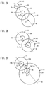
- FIG. 12A is an explanatory diagram showing a positional relationship between the lateral load F applied to the counter shaft by the first counter gear and the lateral load aF applied to the counter shaft by the second counter gear in the second electric vehicle;
- FIG. 12B is a BMD for a case in which the lateral load F is applied by the first counter gear
- FIG. 12C is a BMD for a case in which the lateral load aF is applied by the second counter gear
- FIG. 13A is a BMD for a case in which the lateral load F is applied by the first counter gear
- FIG. 13B is a BMD for a case in which the lateral load aF is applied by the second counter gear.
- FIG. 13C is a BMD showing a state in which a region is generated in which a slope of the bending moment becomes a minimum value or zero between the first counter gear and the second bearing.
- Embodiments of an electric vehicle according to the present invention will be described below with reference to FIGS. 1A to 13C .
- an electric vehicle according to a first embodiment (hereinafter referred to as a first electric vehicle 10 A) includes a motor shaft 14 , a counter shaft 16 , and a drive shaft 18 for each of respective drive wheels 12 .
- a motor shaft 14 for example, in the case of four wheels, four motor shafts 14 , four counter shafts 16 , and four drive shafts 18 are included, and in the case of two wheels, two motor shafts 14 , two counter shafts 16 , and two drive shafts 18 are included.
- two drive wheels 12 may be connected to the drive shaft 18 via a differential device (not shown).
- a generator, a battery, or the like, neither of which is shown, may be provided.
- a non-illustrated engine is mounted therein.
- the first electric vehicle 10 A includes a drive motor 20 , the above-described motor shaft 14 connected to the drive motor 20 , a main shaft 24 coupled via a spline 22 to the motor shaft 14 , the above-described counter shaft 16 coupled with the main shaft 24 , a drive shaft 18 coupled with the counter shaft 16 , and a drive wheel 12 coupled with the drive shaft 18 .
- one main gear 26 that rotates integrally with the main shaft 24 is fixed to the main shaft 24 .
- One drive gear 28 that rotates integrally with the drive shaft 18 is fixed to the drive shaft 18 .
- a first counter gear 30 A that rotates integrally with the counter shaft 16 and engages with the main gear 26 is fixed in the vicinity of one end of the counter shaft 16
- a second counter gear 30 B that rotates integrally with the counter shaft 16 and engages with the drive gear 28 is fixed in the vicinity of the other end of the counter shaft 16 .
- the first electric vehicle 10 A includes two bearings 32 a and 32 b , for example, that support the motor shaft 14 , two bearings 34 a and 34 b , for example, that support the main shaft 24 , and two bearings 36 a and 36 b , for example, that support the drive shaft 18 .
- the first electric vehicle 10 A includes three bearings (a first bearing 38 A, a second bearing 38 B, and a third bearing 38 C) that support the counter shaft 16 .
- the first bearing 38 A supports one end portion thereof in the vicinity of the drive motor 20
- the second bearing 38 B supports a location in the vicinity of the center of the counter shaft 16
- the third bearing 38 C supports another end portion thereof in the vicinity of the drive wheel 12 .
- the first counter gear 30 A is fixed between the first bearing 38 A and the second bearing 38 B
- the second counter gear 30 B is fixed between the second bearing 38 B and the third bearing 38 C.
- a torque sensor 42 is disposed on an outer periphery of the counter shaft 16 .
- the torque sensor 42 is disposed in a region where the slope of the bending moment occurring on the counter shaft 16 is minimum.
- a magnetostrictive torque sensor for example, is preferably adopted as the torque sensor 42 .
- the torque sensor 42 includes a plurality of magnetostrictive layers 100 a and 100 b , and a plurality of coils 102 a and 102 b .
- the magnetostrictive layers 100 a and 100 b are disposed on an outer peripheral surface of the counter shaft 16 .
- the magnetostrictive layers 100 a and 100 b are formed by plating.
- the magnetostrictive layers 100 a and 100 b may be constituted by grooves formed by a knurling process, magnetostrictive metallic films affixed using an adhesive, or press-fitted annular magnetostrictive metallic members.
- the coils 102 a and 102 b are disposed in a cylinder 104 that is fixed to a non-illustrated support member.
- a positional relationship between the motor shaft 14 , the counter shaft 16 , and the drive shaft 18 is preferably defined in a manner so that, when viewed in an axial cross-section of the motor shaft 14 , the counter shaft 16 , and the drive shaft 18 , the respective axial centers O 1 , O 2 , and O 3 of the motor shaft 14 , the counter shaft 16 , and the drive shaft 18 are aligned on a straight line 44 . Consequently, the problem of loads from the motor shaft 14 and the drive shaft 18 being applied with respect to the counter shaft 16 can be simplified into a problem of bending a beam that is subjected to a lateral load.
- the positional relationship between the motor shaft 14 and the drive shaft 18 may be coaxial when viewed in an axial cross section of each of the shafts.
- the positional relationship between the motor shaft 14 and the drive shaft 18 may be defined in a manner so that, when viewed in an axial cross-section of each of the shafts, the centers of the respective shafts are aligned on the straight line 44 , and the axial center O 1 of the motor shaft 14 may be disposed on a line segment 44 a between the axial center O 2 of the counter shaft 16 and the axial center O 3 of the drive shaft 18 .
- the counter shaft 16 is supported by the first bearing 38 A, the second bearing 38 B, and the third bearing 38 C, and is subjected to the lateral loads F and aF, respectively, by the first counter gear 30 A and the second counter gear 30 B, such a situation can be regarded as a problem of bending a beam that is supported at three points (hereinafter referred to as a three-point-supported beam).
- the term “a” indicates a gear ratio between the first counter gear 30 A and the second counter gear 30 B.
- FIG. 3A is a deflection curve diagram showing a deflection curve of the counter shaft 16 in the case that the lateral load F is received by the first counter gear 30 A
- FIG. 3D shows a BMD (bending moment diagram) showing the bending moment occurring on the counter shaft 16 .
- the distance between the first bearing 38 A and the second bearing 38 B is l 1
- the distance between the second bearing 38 B and the third bearing 38 C is l 2
- the distance between the first bearing 38 A and the first counter gear 30 A is l 3
- the distance between the first counter gear 30 A and the second bearing 38 B is l 4
- the distance between the second bearing 38 B and the second counter gear 30 B is l 5
- the distance between the second counter gear 30 B and the third bearing 38 C is l 6
- the terms f 1 , f 2 , and f 3 indicate lateral loads occurring on the first bearing 38 A, the second bearing 38 B, and the third bearing 38 C, respectively.
- the deflection of the beam in the three-point-supported beam which is shown in FIG. 3A can be expressed as a superposition of the deflection curve diagram shown in FIG. 3B and the deflection curve diagram shown in FIG. 3C .
- the BMD in relation to the three-point-supported beam which is shown in FIG. 3D can be expressed as a superposition of the BMD shown in FIG. 3E and the BMD shown in FIG. 3F .
- ⁇ 2 f 3 ′′ ⁇ l 2 ⁇ l 1 3 ⁇ EI ( 6 )
- ⁇ 22 f 3 ′′ ⁇ l 2 3 3 ⁇ EI ( 8 )
- the bending moment M1 at the position of the first counter gear 30 A can be determined by substituting the above-described expression (3) and expression (10) into the above-described expression (1).
- the bending moment M2 at the position of the second bearing 38 B can be determined by substituting the above-described expression (10) into the above-described expression (2).
- the BMD in the case that the lateral load F is applied by the first counter gear 30 A to the three-point-supported beam, the BMD becomes as shown in FIG. 5 .
- the slope A1 of the bending moment between the first bearing 38 A and the first counter gear 30 A, the slope A2 of the bending moment between the first counter gear 30 A and the second bearing 38 B, and the slope A3 of the bending moment between the second bearing 38 B and the third bearing 38 C are as shown by the following expressions.
- FIG. 6A is a deflection curve diagram showing a deflection curve of the counter shaft 16 in the case that the lateral load aF is received by the second counter gear 30 B
- FIG. 6D shows a BMD (bending moment diagram) showing the bending moment occurring on the counter shaft 16
- the terms g 1 , g 2 , and g 3 indicate lateral loads occurring on the first bearing 38 A, the second bearing 38 B, and the third bearing 38 C.
- the deflection of the beam in the three-point-supported beam which is shown in FIG. 6A can be expressed as a superposition of the deflection curve diagram shown in FIG. 6B and the deflection curve diagram shown in FIG. 6C .
- the BMD in relation to the three-point-supported beam which is shown in FIG. 6D can be expressed as a superposition of the BMD shown in FIG. 6E and the BMD shown in FIG. 6F .
- M ⁇ ⁇ 3 g 1 ′′ ⁇ l 1 ( 1 ) ′
- M ⁇ ⁇ 4 g 3 ′ ⁇ l 6 + g 1 ′′ ⁇ l 1 ⁇ l 6 l 2 ( 2 ) ′
- the bending moment M3 at the position of the second bearing 38 B can be determined by substituting the above-described expression (10)′ into the above-described expression (1)′.
- the bending moment M4 at the position of the second counter gear 30 B can be determined by substituting the above-described expressions (3)′ and (10)′ into the above-described expression (2)′.
- the BMD in the case that the lateral load aF is applied by the second counter gear 30 B to the three-point-supported beam, the BMD becomes as shown in FIG. 8 .
- the slope B1 of the bending moment (see FIG. 9C ) between the first bearing 38 A and the second bearing 38 B, and the slope B2 of the bending moment (see FIG. 9C ) between the second bearing 38 B and the second counter gear 30 B are as shown by the following expressions.
- the BMD of the counter shaft 16 can be determined by superimposing the BMD (see FIG. 9B ) due to the lateral load F of the first counter gear 30 A, and the BMD (see FIG. 9C ) due to the lateral load aF of the second counter gear 30 B.
- the first method is a case in which the slope A1 between the first counter gear 30 A and the second bearing 38 B in the BMD of FIG. 9B , and the slope B1 between the first bearing 38 A and the second bearing 38 B in the BMD of FIG. 9C are made equal (if positive and negative values are opposite, the absolute values thereof are made equal).
- first counter gear 30 A, the second counter gear 30 B, the first bearing 38 A, the second bearing 38 B, and the third bearing 38 C are disposed in a positional relationship that satisfies the following equation (15)′.
- the second method is a case in which the slope A3 between the second bearing 38 B and the third bearing 38 C in the BMD of FIG. 9B is made equal to the slope B2 between the second bearing 38 B and the second counter gear 30 B in the BMD of FIG. 9C .
- first counter gear 30 A, the second counter gear 30 B, the first bearing 38 A, the second bearing 38 B, and the third bearing 38 C are disposed in a positional relationship that satisfies the following equation (15)′′.
- the torque sensor 42 is disposed in the region between the first counter gear 30 A and the second bearing 38 B, or alternatively, in the region between the second bearing 38 B and the second counter gear 30 B.
- a second electric vehicle 10 B an electric vehicle according to a second embodiment (hereinafter referred to as a second electric vehicle 10 B) will be described with reference to FIGS. 11 to 13C .
- the second electric vehicle 10 B has substantially the same configuration as the first electric vehicle 10 A described above, but as shown in FIG. 11 , differs therefrom in that the bearings that support the counter shaft 16 are two bearings (the first bearing 38 A and the second bearing 38 B).
- the first bearing 38 A supports one end portion thereof in the vicinity of the drive motor 20
- the second bearing 38 B supports another end portion thereof in the vicinity of the drive wheel 12 .
- the first counter gear 30 A and the second counter gear 30 B are fixed between the first bearing 38 A and the second bearing 38 B.
- the torque sensor 42 is disposed in a region where the slope of the bending moment occurring on the counter shaft 16 is a minimum value or zero.
- the BMD which indicates the bending moment occurring on the counter shaft 16 can be determined by superimposing the BMD (see FIG. 12B ) due to the lateral load F of the first counter gear 30 A, and the BMD (see FIG. 12C ) due to the lateral load aF of the second counter gear 30 B.
- the distance between the first bearing 38 A and the second bearing 38 B is L
- the distance between the first bearing 38 A and the first counter gear 30 A is L 1
- the distance between the first counter gear 30 A and the second counter gear 30 B is L 2 .
- Lateral loads fa and fb occurring on the first bearing 38 A and the second bearing 38 B due to the lateral load F of the first counter gear 30 A, and a bending moment Ma at the position of the first counter gear 30 A are as follows.
- fa L - L 1 L ⁇ F ( 16 )
- fb L 1 L ⁇ F ( 17 )
- Ma L 1 ⁇ ( L - L 1 ) L ⁇ F ( 18 )
- the slope A of the bending moment between the first counter gear 30 A and the second bearing 38 B is as follows.
- lateral loads ga and gb occurring on the first bearing 38 A and the second bearing 38 B due to the lateral load aF of the second counter gear 30 B, and a bending moment Mb at the position of the second counter gear 30 B are as follows.
- ga L - L 1 - L 2 L ⁇ aF ( 20 )
- gb L 1 + L 2 L ⁇ aF ( 21 )
- Mb ( L 1 + L 2 ) ⁇ ( L - L 1 - L 2 ) L ⁇ aF ( 22 )
- the slope B of the bending moment between the first bearing 38 A and the second counter gear 30 B is as follows.
- a region Z where the slope of the bending moment is a minimum value or zero is generated between the first counter gear 30 A and the second counter gear 30 B. More specifically, the first bearing 38 A, the second bearing 38 B, the first counter gear 30 A, and the second counter gear 30 B are disposed in a positional relationship that satisfies the following equation (24).
- the torque sensor 42 is disposed in the region between the first counter gear 30 A and the second counter gear 30 B.
- the electric vehicle includes the drive motor 20 , the motor shaft 14 connected to the drive motor 20 , the counter shaft 16 coupled with the motor shaft 14 , the drive shaft 18 coupled with the counter shaft 16 , the drive wheel 12 coupled with the drive shaft 18 , the plurality of bearings configured to support the counter shaft 16 , and the plurality of gears 30 A and 30 B configured to rotate integrally with the counter shaft 16 , wherein the torque sensor 42 is disposed in a region in which the slope of the bending moment occurring on the counter shaft 16 is minimum at the time that the drive motor 20 is driven.
- the first electric vehicle 10 A includes the drive motor 20 , the motor shaft 14 connected to the drive motor 20 , the counter shaft 16 coupled with the motor shaft 14 , the drive shaft 18 coupled with the counter shaft 16 , the drive wheel 12 coupled with the drive shaft 18 , the first bearing 38 A, the second bearing 38 B, and the third bearing 38 C configured to support the counter shaft 16 , and the first counter gear 30 A and the second counter gear 30 B configured to rotate integrally with the counter shaft 16 , wherein a positional relationship between the motor shaft 14 , the counter shaft 16 , and the drive shaft 18 is defined in a manner so that, when viewed in an axial cross-section of the motor shaft 14 , the counter shaft 16 , and the drive shaft 18 , respective centers of the motor shaft 14 , the counter shaft 16 , and the drive shaft 18 are aligned respectively on the straight line 44 , and assuming that a lateral load by the first counter gear 30 A is represented by F, a lateral load by the second counter gear 30 B is represented by a
- the problem of loads from the motor shaft 14 and the drive shaft 18 being applied with respect to the counter shaft 16 can be simplified into a problem of bending a beam that is subjected to a lateral load. As a result, it is possible to easily determine the region in which the slope of the bending moment occurring on the counter shaft 16 is minimum.
- the torque sensor 42 is disposed within the counter shaft 16 between the first counter gear 30 A and the second bearing 38 B. More specifically, in the case that the above-described expression (25) is satisfied, at a time that the drive motor 20 is driven, the region in which the slope of the bending moment occurring on the counter shaft 16 is minimum is the region Z 1 between the first counter gear 30 A and the second bearing 38 B. By arranging the torque sensor 42 in the region Z 1 , it is possible to accurately detect the torque that is applied to the counter shaft 16 .
- the torque sensor 42 is disposed within the counter shaft 16 between the second bearing 38 B and the second counter gear 30 B.
- the region in which the slope of the bending moment occurring on the counter shaft 16 is minimum is the region Z 2 between the second bearing 38 B and the second counter gear 30 B.
- the second electric vehicle 10 B includes the drive motor 20 , the motor shaft 14 connected to the drive motor 20 , the counter shaft 16 coupled with the motor shaft 14 , the drive shaft 18 coupled with the counter shaft 16 , the drive wheel 12 coupled with the drive shaft 18 , the first bearing 38 A and the second bearing 38 B configured to support the counter shaft 16 , and the first counter gear 30 A and the second counter gear 30 B configured to rotate integrally with the counter shaft 16 , wherein a positional relationship between the motor shaft 14 , the counter shaft 16 , and the drive shaft 18 is defined in a manner so that, when viewed in an axial cross-section of the motor shaft 14 , the counter shaft 16 , and the drive shaft 18 , respective centers of the motor shaft 14 , the counter shaft 16 , and the drive shaft 18 are aligned respectively on the straight line 44 , and assuming that a lateral load by the first counter gear 30 A is represented by F, a lateral load by the second counter gear 30 B is represented by aF where “a” indicates
- the problem of loads from the motor shaft 14 and the drive shaft 18 being applied with respect to the counter shaft 16 can be simplified into a problem of bending a beam that is subjected to a lateral load. As a result, it is possible to easily determine the region in which the slope of the bending moment occurring on the counter shaft 16 is minimum.
- the torque sensor 42 is disposed within the counter shaft 16 between the first counter gear 30 A and the second counter gear 30 B.
- the region in which the slope of the bending moment occurring on the counter shaft 16 is minimum is the region Z between the first counter gear 30 A and the second counter gear 30 B.
- the positional relationship between the motor shaft 14 and the drive shaft 18 is coaxial when viewed in an axial cross-section of each of the shafts.
- the drive motor 20 and the drive wheel 12 can be disposed coaxially, and the drive unit of the electric vehicle can be made compact.
- the gear diameter of the drive shaft 18 is fixed, the above-described gear ratio “a” of the counter shaft 16 can be changed by appropriately changing the diameter of the motor shaft 14 .
- the positional relationship between the motor shaft 14 and the drive shaft 18 is defined in a manner so that, when viewed in an axial cross-section of each of the shafts, the centers of the respective shafts are aligned on the straight line 44 , and the center of the motor shaft 14 is disposed on the line segment 44 a between the axial center O 2 of the counter shaft 16 and the axial center O 3 of the drive shaft 18 .
- the axial center O 1 of the motor shaft 14 can be accommodated within a circle of the drive wheel 12 , and the drive unit of the electric vehicle can be made compact.
- the above-described gear ratio “a” of the counter shaft 16 can be changed by appropriately changing the diameter of the motor shaft 14 , or alternatively, by appropriately changing the position of the motor shaft 14 on the above-described line segment 44 a.
- the present invention is not limited to the embodiments described above, and it goes without saying that the present invention can be freely modified within a range that does not depart from the essence and gist of the present invention.
Landscapes
- Engineering & Computer Science (AREA)
- Mechanical Engineering (AREA)
- General Engineering & Computer Science (AREA)
- Chemical & Material Sciences (AREA)
- Combustion & Propulsion (AREA)
- Transportation (AREA)
- Gear Transmission (AREA)
- Electric Propulsion And Braking For Vehicles (AREA)
Abstract
Description
Claims (10)
Applications Claiming Priority (3)
| Application Number | Priority Date | Filing Date | Title |
|---|---|---|---|
| JP2018-061435 | 2018-03-28 | ||
| JP2018061435A JP2019174235A (en) | 2018-03-28 | 2018-03-28 | Electric vehicle |
| JPJP2018-061435 | 2018-03-28 |
Publications (2)
| Publication Number | Publication Date |
|---|---|
| US20190299776A1 US20190299776A1 (en) | 2019-10-03 |
| US11142064B2 true US11142064B2 (en) | 2021-10-12 |
Family
ID=68056695
Family Applications (1)
| Application Number | Title | Priority Date | Filing Date |
|---|---|---|---|
| US16/366,001 Expired - Fee Related US11142064B2 (en) | 2018-03-28 | 2019-03-27 | Electric vehicle |
Country Status (3)
| Country | Link |
|---|---|
| US (1) | US11142064B2 (en) |
| JP (1) | JP2019174235A (en) |
| CN (1) | CN110316109B (en) |
Citations (7)
| Publication number | Priority date | Publication date | Assignee | Title |
|---|---|---|---|---|
| US20110298314A1 (en) * | 2010-06-08 | 2011-12-08 | Aisin Aw Co., Ltd. | Vehicle drive system |
| US20120143422A1 (en) * | 2010-12-06 | 2012-06-07 | Aisin Aw Co., Ltd. | Hybrid drive apparatus and controller for hybrid drive apparatus |
| US20130325237A1 (en) * | 2010-03-31 | 2013-12-05 | Honda Motor Co., Ltd. | Control unit for vehicle driving system |
| US20160355084A1 (en) * | 2014-02-18 | 2016-12-08 | Ntn Corporation | Wheel drive motor and in-wheel motor drive assembly |
| JP2017100590A (en) | 2015-12-02 | 2017-06-08 | 本田技研工業株式会社 | vehicle |
| US10337603B2 (en) * | 2015-03-13 | 2019-07-02 | Toyota Jidosha Kabushiki Kaisha | Lubricating structure for hybrid vehicle |
| US10797568B2 (en) * | 2018-03-22 | 2020-10-06 | Honda Motor Co., Ltd. | Motor unit and vehicle |
Family Cites Families (3)
| Publication number | Priority date | Publication date | Assignee | Title |
|---|---|---|---|---|
| WO2010142318A1 (en) * | 2009-06-08 | 2010-12-16 | Abb Technology Ab | A device for measuring torque |
| JP5447031B2 (en) * | 2010-03-12 | 2014-03-19 | トヨタ自動車株式会社 | Vehicle motor drive device |
| JP5894770B2 (en) * | 2011-11-09 | 2016-03-30 | ダイムラー・アクチェンゲゼルシャフトDaimler AG | Control device for hybrid vehicle |
-
2018
- 2018-03-28 JP JP2018061435A patent/JP2019174235A/en active Pending
-
2019
- 2019-03-27 US US16/366,001 patent/US11142064B2/en not_active Expired - Fee Related
- 2019-03-28 CN CN201910245004.9A patent/CN110316109B/en not_active Expired - Fee Related
Patent Citations (8)
| Publication number | Priority date | Publication date | Assignee | Title |
|---|---|---|---|---|
| US20130325237A1 (en) * | 2010-03-31 | 2013-12-05 | Honda Motor Co., Ltd. | Control unit for vehicle driving system |
| US20110298314A1 (en) * | 2010-06-08 | 2011-12-08 | Aisin Aw Co., Ltd. | Vehicle drive system |
| US20120143422A1 (en) * | 2010-12-06 | 2012-06-07 | Aisin Aw Co., Ltd. | Hybrid drive apparatus and controller for hybrid drive apparatus |
| US20160355084A1 (en) * | 2014-02-18 | 2016-12-08 | Ntn Corporation | Wheel drive motor and in-wheel motor drive assembly |
| US10337603B2 (en) * | 2015-03-13 | 2019-07-02 | Toyota Jidosha Kabushiki Kaisha | Lubricating structure for hybrid vehicle |
| JP2017100590A (en) | 2015-12-02 | 2017-06-08 | 本田技研工業株式会社 | vehicle |
| US20170158043A1 (en) | 2015-12-02 | 2017-06-08 | Honda Motor Co., Ltd. | Vehicle |
| US10797568B2 (en) * | 2018-03-22 | 2020-10-06 | Honda Motor Co., Ltd. | Motor unit and vehicle |
Also Published As
| Publication number | Publication date |
|---|---|
| JP2019174235A (en) | 2019-10-10 |
| CN110316109B (en) | 2022-11-29 |
| CN110316109A (en) | 2019-10-11 |
| US20190299776A1 (en) | 2019-10-03 |
Similar Documents
| Publication | Publication Date | Title |
|---|---|---|
| US8886381B2 (en) | Electric vehicle | |
| US11041557B2 (en) | Speed reducer with electric motor | |
| US11990822B2 (en) | Vehicle power unit and vehicle wheel bearing with generator | |
| US11555538B2 (en) | Disconnector apparatus | |
| US11014455B2 (en) | Vehicle drive device | |
| US8858379B2 (en) | Axle assembly having an electric motor module | |
| CN103442930B (en) | Electronlmobil | |
| US9296291B2 (en) | Electric vehicle | |
| EP3643549A1 (en) | Torque limiter for use with a dual planetary/integrated differential drive train | |
| US9729026B2 (en) | In-wheel motor and in-wheel motor driving device | |
| US8880267B2 (en) | Electric automobile | |
| US20130009522A1 (en) | Drive motor for electric vehicle | |
| WO2013128586A1 (en) | Drive device for hybrid vehicle | |
| CN107078575A (en) | rotating electrical machine | |
| US20150236573A1 (en) | Case structure for driving apparatus | |
| US11142064B2 (en) | Electric vehicle | |
| US20150362045A1 (en) | Transmission device | |
| JP6138006B2 (en) | Inertia fixing structure | |
| JP2011172345A (en) | Fixing structure of resolver sensor | |
| US20100326224A1 (en) | Gear device and power transmission apparatus | |
| JP5250942B2 (en) | Rolling bearing device for wheels | |
| JP2020101221A (en) | Drive unit for vehicle | |
| US20260092939A1 (en) | Vehicle assembly, transmission unit, and vehicle | |
| US20250215937A1 (en) | Clutch device | |
| WO2017094420A1 (en) | Rolling bearing unit for drive wheel support |
Legal Events
| Date | Code | Title | Description |
|---|---|---|---|
| AS | Assignment |
Owner name: HONDA MOTOR CO., LTD., JAPAN Free format text: ASSIGNMENT OF ASSIGNORS INTEREST;ASSIGNORS:OHZU, TATSUYA;ARIMURA, YUTAKA;HOSHINO, DAISUKE;AND OTHERS;REEL/FRAME:048712/0149 Effective date: 20190312 |
|
| FEPP | Fee payment procedure |
Free format text: ENTITY STATUS SET TO UNDISCOUNTED (ORIGINAL EVENT CODE: BIG.); ENTITY STATUS OF PATENT OWNER: LARGE ENTITY |
|
| STPP | Information on status: patent application and granting procedure in general |
Free format text: DOCKETED NEW CASE - READY FOR EXAMINATION |
|
| STPP | Information on status: patent application and granting procedure in general |
Free format text: NOTICE OF ALLOWANCE MAILED -- APPLICATION RECEIVED IN OFFICE OF PUBLICATIONS |
|
| STPP | Information on status: patent application and granting procedure in general |
Free format text: PUBLICATIONS -- ISSUE FEE PAYMENT RECEIVED |
|
| STPP | Information on status: patent application and granting procedure in general |
Free format text: PUBLICATIONS -- ISSUE FEE PAYMENT VERIFIED |
|
| STCF | Information on status: patent grant |
Free format text: PATENTED CASE |
|
| FEPP | Fee payment procedure |
Free format text: MAINTENANCE FEE REMINDER MAILED (ORIGINAL EVENT CODE: REM.); ENTITY STATUS OF PATENT OWNER: LARGE ENTITY |
|
| LAPS | Lapse for failure to pay maintenance fees |
Free format text: PATENT EXPIRED FOR FAILURE TO PAY MAINTENANCE FEES (ORIGINAL EVENT CODE: EXP.); ENTITY STATUS OF PATENT OWNER: LARGE ENTITY |
|
| STCH | Information on status: patent discontinuation |
Free format text: PATENT EXPIRED DUE TO NONPAYMENT OF MAINTENANCE FEES UNDER 37 CFR 1.362 |
|
| FP | Lapsed due to failure to pay maintenance fee |
Effective date: 20251012 |