US11133597B2 - Antenna array and wireless device - Google Patents
Antenna array and wireless device Download PDFInfo
- Publication number
- US11133597B2 US11133597B2 US16/847,923 US202016847923A US11133597B2 US 11133597 B2 US11133597 B2 US 11133597B2 US 202016847923 A US202016847923 A US 202016847923A US 11133597 B2 US11133597 B2 US 11133597B2
- Authority
- US
- United States
- Prior art keywords
- radio frequency
- antenna
- dielectric
- lenses
- lens
- Prior art date
- Legal status (The legal status is an assumption and is not a legal conclusion. Google has not performed a legal analysis and makes no representation as to the accuracy of the status listed.)
- Active
Links
Images


Classifications
-
- H—ELECTRICITY
- H01—ELECTRIC ELEMENTS
- H01Q—ANTENNAS, i.e. RADIO AERIALS
- H01Q21/00—Antenna arrays or systems
-
- H—ELECTRICITY
- H01—ELECTRIC ELEMENTS
- H01Q—ANTENNAS, i.e. RADIO AERIALS
- H01Q19/00—Combinations of primary active antenna elements and units with secondary devices, e.g. with quasi-optical devices, for giving the antenna a desired directional characteristic
- H01Q19/06—Combinations of primary active antenna elements and units with secondary devices, e.g. with quasi-optical devices, for giving the antenna a desired directional characteristic using refracting or diffracting devices, e.g. lens
- H01Q19/09—Combinations of primary active antenna elements and units with secondary devices, e.g. with quasi-optical devices, for giving the antenna a desired directional characteristic using refracting or diffracting devices, e.g. lens wherein the primary active element is coated with or embedded in a dielectric or magnetic material
-
- H—ELECTRICITY
- H01—ELECTRIC ELEMENTS
- H01Q—ANTENNAS, i.e. RADIO AERIALS
- H01Q15/00—Devices for reflection, refraction, diffraction or polarisation of waves radiated from an antenna, e.g. quasi-optical devices
- H01Q15/02—Refracting or diffracting devices, e.g. lens, prism
- H01Q15/08—Refracting or diffracting devices, e.g. lens, prism formed of solid dielectric material
-
- H—ELECTRICITY
- H01—ELECTRIC ELEMENTS
- H01Q—ANTENNAS, i.e. RADIO AERIALS
- H01Q19/00—Combinations of primary active antenna elements and units with secondary devices, e.g. with quasi-optical devices, for giving the antenna a desired directional characteristic
- H01Q19/06—Combinations of primary active antenna elements and units with secondary devices, e.g. with quasi-optical devices, for giving the antenna a desired directional characteristic using refracting or diffracting devices, e.g. lens
- H01Q19/062—Combinations of primary active antenna elements and units with secondary devices, e.g. with quasi-optical devices, for giving the antenna a desired directional characteristic using refracting or diffracting devices, e.g. lens for focusing
-
- H—ELECTRICITY
- H01—ELECTRIC ELEMENTS
- H01Q—ANTENNAS, i.e. RADIO AERIALS
- H01Q21/00—Antenna arrays or systems
- H01Q21/0006—Particular feeding systems
- H01Q21/0025—Modular arrays
-
- H—ELECTRICITY
- H01—ELECTRIC ELEMENTS
- H01Q—ANTENNAS, i.e. RADIO AERIALS
- H01Q21/00—Antenna arrays or systems
- H01Q21/06—Arrays of individually energised antenna units similarly polarised and spaced apart
- H01Q21/20—Arrays of individually energised antenna units similarly polarised and spaced apart the units being spaced along or adjacent to a curvilinear path
-
- H—ELECTRICITY
- H01—ELECTRIC ELEMENTS
- H01Q—ANTENNAS, i.e. RADIO AERIALS
- H01Q3/00—Arrangements for changing or varying the orientation or the shape of the directional pattern of the waves radiated from an antenna or antenna system
- H01Q3/26—Arrangements for changing or varying the orientation or the shape of the directional pattern of the waves radiated from an antenna or antenna system varying the relative phase or relative amplitude of energisation between two or more active radiating elements; varying the distribution of energy across a radiating aperture
- H01Q3/30—Arrangements for changing or varying the orientation or the shape of the directional pattern of the waves radiated from an antenna or antenna system varying the relative phase or relative amplitude of energisation between two or more active radiating elements; varying the distribution of energy across a radiating aperture varying the relative phase between the radiating elements of an array
-
- H—ELECTRICITY
- H01—ELECTRIC ELEMENTS
- H01Q—ANTENNAS, i.e. RADIO AERIALS
- H01Q3/00—Arrangements for changing or varying the orientation or the shape of the directional pattern of the waves radiated from an antenna or antenna system
- H01Q3/44—Arrangements for changing or varying the orientation or the shape of the directional pattern of the waves radiated from an antenna or antenna system varying the electric or magnetic characteristics of reflecting, refracting, or diffracting devices associated with the radiating element
- H01Q3/46—Active lenses or reflecting arrays
Definitions
- This application relates to the communications field, and in particular, to an antenna array and a wireless device.
- Multiple-input and multiple-output uses an antenna array to receive or send signals to improve a wireless communication capacity, and is a wireless transmission technology widely used in a wireless communications system such as a cellular mobile communications system or a wireless local area network (English: wireless local area network, WLAN).
- a spacing between adjacent antennas in an MIMO antenna array needs to be at least 0.5 ⁇ Otherwise, radiation efficiency of the antenna is reduced, and therefore MIMO performance is deteriorated.
- ⁇ is a free space wavelength of a radio frequency carrier.
- a spacing 0.7 ⁇ between adjacent antennas in an antenna array is usually used in an actual application.
- the antenna array is widely applied to fields such as beamforming, estimation of beam arrival direction, beam tracking, and microwave imaging. These applications require that the spacing between the adjacent antennas needs to be at least 0.5 ⁇ .
- due to engineering limitations such as appearance, wind resistance, load bearing, and costs, a size of the antenna array cannot be too large. This conflicts with a requirement for a large quantity of antennas.
- This application provides an antenna array and a wireless device, to improve MIMO performance per unit size.
- an antenna array includes a first antenna set and a first radio frequency lens set.
- the first antenna set includes a plurality of antennas.
- the first radio frequency lens set includes a plurality of radio frequency lenses.
- the plurality of antennas in the first antenna set and the plurality of radio frequency lenses in the first radio frequency lens set are arranged according to rules.
- the rules include:
- the plurality of radio frequency lenses are in a one-to-one correspondence with the plurality of antennas, and each radio frequency lens is arranged on a corresponding antenna.
- Any one of the plurality of radio frequency lenses includes two or more parts whose wavefront phase adjustment amounts are different, and wavefront phase adjustment amounts of the plurality of radio frequency lenses in any direction of arrival (English: direction of arrival, DOA) meet the following conditions: A plurality of wavefront phase adjustment amounts of the plurality of radio frequency lenses in a direction of arrival are monotonically increasing along the direction; and at least two of the plurality of wavefront phase adjustment amounts of the plurality of radio frequency lenses in the direction of arrival are different.
- the radio frequency lens increases or at least does not decrease an equivalent wave path difference between an electromagnetic wave that arrives at a farther antenna and an electromagnetic wave that arrives at a nearer antenna, to increase a phase difference between radio signals from the antennas.
- MIMO performance is related to a coupling between the radio signals from the antennas. A larger phase difference between the radio signals from the antennas indicates a lower coupling. Therefore, the antenna array has better MIMO performance per unit size.
- the plurality of radio frequency lenses are in a one-to-one correspondence with the plurality of wavefront phase adjustment amounts of the plurality of radio frequency lenses in the direction of arrival.
- a wavefront phase adjustment amount of one of the plurality of radio frequency lenses in the direction of arrival is a wavefront phase adjustment amount of a part that is in all parts of the radio frequency lens and through which a corresponding path straight line passes.
- the corresponding path straight line is a straight line that is along the direction of arrival and that passes through an antenna corresponding to the radio frequency lens.
- An order of the plurality of wavefront phase adjustment amounts along the direction of arrival is an order of projections that are of a plurality of corresponding antennas on a reference straight line and that are arranged on the reference straight line along the direction.
- the reference straight line may be any straight line along the direction of arrival.
- the plurality of radio frequency lenses in the first radio frequency lens set are a plurality of dielectric lenses.
- Any one of the plurality of dielectric lenses includes two or more parts with different materials, and dielectric constants of the different materials are different.
- Wavefront phase adjustment amounts of two parts with a same thickness are related to dielectric constants of materials of the corresponding parts.
- a larger dielectric constant indicates a larger wavefront phase adjustment amount. Because a relative magnetic permeability of a magnetic material in a gigahertz frequency band is usually close to 1, it is a simple choice to make a radio frequency lens by using a high dielectric constant material in the gigahertz frequency band and a frequency band above gigahertz.
- the plurality of radio frequency lenses are a plurality of dielectric hemispheres.
- the plurality of antennas in the first antenna set are respectively located at sphere centers of corresponding dielectric hemispheres in the first radio frequency lens set.
- An incident electromagnetic wave is exactly perpendicular to a surface of the radio frequency lens by using a hemispherical dielectric lens, so that a propagation direction is not changed when refraction occurs.
- At least one part of at least one dielectric lens in the first radio frequency lens set includes an anti-reflection structure.
- the anti-reflection structure is on a surface of the part.
- a dielectric constant of a material of the anti-reflection structure is less than a dielectric constant of the part.
- a thickness of the anti-reflection structure is one quarter of a wavelength of an electromagnetic wave in the material of the anti-reflection structure. The electromagnetic wave is reflected when passing through an interface between materials with different refractive indexes. Therefore, to reduce reflection of the electromagnetic wave on a surface of the dielectric lens, the anti-reflection structure may be added to the dielectric lens.
- a principle of the anti-reflection structure is the same as that of applying an anti-reflection coating to a surface of an optical glass to improve light transmittance. Further, to minimize reflection of the electromagnetic wave, a refractive index of the material of the anti-reflection structure is a geometric average value of refractive indexes of two materials on two sides of the anti-reflection structure.
- the at least one dielectric lens in the first radio frequency lens set includes a fusion structure.
- the fusion structure is between an antenna corresponding to the dielectric lens and an interface between parts of the dielectric lens.
- a dielectric constant of a material of the fusion structure is less than a smallest dielectric constant of materials of the parts of the dielectric lens.
- the electromagnetic wave is reflected when passing through an interface between materials with different refractive indexes. Therefore, to reduce reflection of the electromagnetic wave on the interface between the different materials in the dielectric lens, the fusion structure may be added to the dielectric lens.
- a surface of the fusion structure is bent, for example, in an arc shape, so that the electromagnetic wave passes through the surface at a large angle, to reduce reflection of the electromagnetic wave.
- the plurality of antennas in the first antenna set are patch antennas or on-chip antennas.
- the plurality of antennas in the first antenna set are arranged in a column along a straight line, and each dielectric lens includes two parts that are with different materials but a same size. An interface between the two parts is perpendicular to the straight line.
- Dielectric constants of materials of all left parts in all pairs of the two parts of the plurality of dielectric lenses in the first radio frequency lens set are strictly monotonically increasing along the straight line from left to right.
- Dielectric constants of materials of all right parts in all pairs of the two parts of the plurality of dielectric lenses in the first radio frequency lens set are strictly monotonically decreasing along the straight line from left to right.
- the antenna array further includes a second antenna set and a second radio frequency lens set.
- the second antenna set includes a plurality of antennas.
- the second radio frequency lens set includes a plurality of radio frequency lenses.
- the plurality of antennas in the second antenna set and the plurality of radio frequency lenses in the second radio frequency lens set are arranged according to the rules.
- Polarization directions of the plurality of antennas in the first antenna set are the same.
- Polarization directions of the plurality of antennas in the second antenna set are the same.
- a polarization direction of any antenna in the first antenna set is orthogonal to a polarization direction of any antenna in the second antenna set.
- an antenna array includes eight antennas arranged on a plane and eight radio frequency lenses.
- the eight antennas are arranged in a regular octagon.
- the eight radio frequency lenses are in a one-to-one correspondence with the eight antennas.
- Each radio frequency lens is arranged on a corresponding antenna.
- Any one of the eight radio frequency lenses includes four areas with a same size.
- An angle of 45 degrees is formed between a first straight line along a front-to-rear direction and each of interfaces between the four areas in the any radio frequency lens, and an angle of 45 degrees is formed between a second straight line along a left-to-right direction and each of the interfaces between the four areas in the any radio frequency lens.
- Wavefront phase adjustment amounts of all front areas in all combinations of the four areas in all of the eight radio frequency lenses are strictly monotonically increasing along the first straight line from front to rear.
- Wavefront phase adjustment amounts of all rear areas in all combinations of the four areas in all of the eight radio frequency lenses are strictly monotonically decreasing along the first straight line from front to rear.
- Wavefront phase adjustment amounts of all left areas in all combinations of the four areas in all of the eight radio frequency lenses are strictly monotonically increasing along the second straight line from left to right.
- Wavefront phase adjustment amounts of all right areas in all combinations of the four areas in all of the eight radio frequency lenses are strictly monotonically decreasing along the second straight line from left to right.
- the eight radio frequency lenses are eight dielectric lenses. Adjacent areas with different wavefront phase adjustment amounts in the areas belong to different parts, materials of the different parts are different, and dielectric constants of the different materials are different. Wavefront phase adjustment amounts of two parts with a same thickness are related to dielectric constants of materials of the corresponding parts. A larger dielectric constant indicates a larger wavefront phase adjustment amount.
- the eight radio frequency lenses are eight dielectric hemispheres.
- the eight antennas are located at sphere centers of corresponding dielectric hemispheres.
- At least one part of at least one of the eight radio frequency lenses includes an anti-reflection structure.
- the anti-reflection structure is on a surface of the part.
- a dielectric constant of a material of the anti-reflection structure is less than a dielectric constant of the part.
- a thickness of the anti-reflection structure is one quarter of a wavelength of an electromagnetic wave in the material of the anti-reflection structure.
- the at least one of the eight radio frequency lenses includes a fusion structure.
- the fusion structure is between an antenna corresponding to the radio frequency lens and an interface between parts of the radio frequency lens.
- a dielectric constant of a material of the fusion structure is less than a smallest dielectric constant of materials of the parts of the radio frequency lens.
- the eight antennas are patch antennas or on-chip antennas.
- an antenna array includes a plurality of antennas arranged on a plane and a plurality of radio frequency lenses.
- the plurality of antennas are arranged in a rectangle.
- the plurality of radio frequency lenses are in a one-to-one correspondence with the plurality of antennas.
- Each radio frequency lens is arranged on a corresponding antenna.
- Any one of the plurality of radio frequency lenses includes four areas with a same size. Interfaces between the four areas in the any radio frequency lens are perpendicular to the plane. Interfaces between the four areas in the any radio frequency lens are at least parallel to one side of the rectangle. Wavefront phase adjustment amounts of all left front areas in any row of radio frequency lenses in the plurality of radio frequency lenses are strictly monotonically increasing from left to right.
- Wavefront phase adjustment amounts of all left rear areas in any row of radio frequency lenses in the plurality of radio frequency lenses are strictly monotonically increasing from left to right. Wavefront phase adjustment amounts of all right front areas in any row of radio frequency lenses in the plurality of radio frequency lenses are strictly monotonically decreasing from left to right. Wavefront phase adjustment amounts of all right rear areas in any row of radio frequency lenses in the plurality of radio frequency lenses are strictly monotonically decreasing from left to right. Wavefront phase adjustment amounts of all left front areas in any column of radio frequency lenses in the plurality of radio frequency lenses are strictly monotonically increasing from front to rear. Wavefront phase adjustment amounts of all left rear areas in any column of radio frequency lenses in the plurality of radio frequency lenses are strictly monotonically decreasing from front to rear.
- Wavefront phase adjustment amounts of all right front areas in any column of radio frequency lenses in the plurality of radio frequency lenses are strictly monotonically increasing from front to rear.
- Wavefront phase adjustment amounts of all right rear areas in any column of radio frequency lenses in the plurality of radio frequency lenses are strictly monotonically decreasing from front to rear.
- the plurality of radio frequency lenses are a plurality of dielectric lenses. Adjacent areas with different wavefront phase adjustment amounts in the areas belong to different parts, materials of the different parts are different, and dielectric constants of the different materials are different. Wavefront phase adjustment amounts of two parts with a same thickness are related to dielectric constants of materials of the corresponding parts. A larger dielectric constant indicates a larger wavefront phase adjustment amount.
- the plurality of radio frequency lenses are a plurality of dielectric hemispheres.
- the plurality of antennas are located at sphere centers of corresponding dielectric hemispheres.
- At least one part of at least one of the plurality of radio frequency lenses includes an anti-reflection structure.
- the anti-reflection structure is on a surface of the part.
- a dielectric constant of a material of the anti-reflection structure is less than a dielectric constant of the part.
- a thickness of the anti-reflection structure is one quarter of a wavelength of an electromagnetic wave in the material of the anti-reflection structure.
- the at least one of the plurality of radio frequency lenses includes a fusion structure.
- the fusion structure is between an antenna corresponding to the radio frequency lens and an interface between parts of the radio frequency lens.
- a dielectric constant of a material of the fusion structure is less than a smallest dielectric constant of materials of the parts of the radio frequency lens.
- the plurality of antennas are patch antennas or on-chip antennas.
- a wireless device includes the antenna array according to the first aspect, the second aspect, the third aspect, or any implementation of any one of the foregoing aspects.
- the wireless device further includes a radio frequency circuit connected to the antenna array.
- the radio frequency circuit is configured to: receive or send signals by using the antenna array.
- the radio frequency circuit is configured to: receive or send the signals by using the antenna array in a multiple-input multiple-output manner.
- FIG. 1 is a structural diagram of an example of an antenna array according to an embodiment of the present invention.
- FIG. 2 is a conceptual diagram according to an embodiment of the present invention.
- FIG. 3 is a schematic diagram of an image obtained by projecting a plurality of antennas onto a direction of arrival of a radio signal according to an embodiment of the present invention
- FIG. 4 shows another example of an antenna array according to an embodiment of the present invention
- FIG. 5 is a structural diagram of a dielectric lens including an anti-reflection structure according to an embodiment of the present invention.
- FIG. 6 is a schematic diagram in which an electromagnetic wave is reflected when passing through an interface between materials with different refractive indexes according to an embodiment of the present invention
- FIG. 7 is a structural diagram of a dielectric lens obtained after a fusion structure is added according to an embodiment of the present invention.
- FIG. 8 shows an example 1 of an antenna array arranged as a rectangle according to an embodiment of the present invention
- FIG. 9 shows an example 2 of an antenna array arranged as a rectangle according to an embodiment of the present invention.
- FIG. 10 shows an example 3 of an antenna array arranged as a rectangle according to an embodiment of the present invention
- FIG. 11 shows an example 4 of an antenna array arranged as a rectangle according to an embodiment of the present invention
- FIG. 12 shows an example 1 of an antenna array arranged as a rhombus according to an embodiment of the present invention
- FIG. 13 shows an example 2 of an antenna array arranged as a rhombus according to an embodiment of the present invention
- FIG. 14 shows an antenna array arranged as a triangle according to an embodiment of the present invention
- FIG. 15 shows an antenna array arranged as a hexagon according to an embodiment of the present invention
- FIG. 16 shows an antenna array including a plurality of independent antenna sets according to an embodiment of the present invention
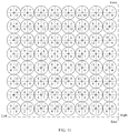
- FIG. 17 shows an example of an antenna array arranged as a circle according to an embodiment of the present invention.
- FIG. 18 is a schematic diagram of a wireless device according to an embodiment of the present invention.
- FIG. 1 is a structural diagram of an example of an antenna array according to an embodiment of the present invention.
- FIG. 2 is a conceptual diagram according to an embodiment of the present invention.
- MIMO performance is greatly affected by a correlation between MIMO channels.
- a stronger correlation between the MIMO channels indicates poorer MIMO performance.
- the correlation between the MIMO channels is related to a phase difference between radio signals from antennas.
- a smaller spacing between adjacent antennas indicates a smaller phase difference between radio signals from antennas and a stronger correlation between MIMO channels.
- a radio frequency lens is used to increase the phase difference between the radio signals from the antennas.
- Each radio frequency lens covers or wraps a corresponding antenna.
- the antenna in the antenna array may be a patch antenna on a printed circuit board or another carrier.
- a patch antenna on a chip using a semiconductor process namely, an on-chip antenna (English: on-chip antenna) is used as the antenna in the antenna array.
- the antenna in the antenna array may alternatively be another flat antenna.
- the antenna array may be arranged on a plane.
- the antenna array may alternatively be arranged on a non-plane.
- the antenna array is arranged on a curved surface, or arranged on a step-shaped bottom plate.
- An arrangement of the antenna array may be higher in the middle and lower in the surroundings.
- the radio frequency lens is a device that can change a wavefront phase obtained when a radio signal arrives at an antenna.
- the radio frequency lens or a part of the radio frequency lens may be made of a dielectric, and a refractive index of the dielectric is higher than a refractive index of air.
- the radio frequency lens may be made of a material whose dielectric constant or magnetic permeability is different from that of air. Because dielectric constants or magnetic permeabilities of different materials may vary with a frequency of the radio signal, a material of which the radio frequency lens is made may be selected based on an applicable frequency of the antenna array.
- a relative magnetic permeability of a magnetic material in a gigahertz (GHz) frequency band is usually close to 1, it is a better choice to make the radio frequency lens by using a high dielectric constant material in the GHz frequency band and a frequency band above GHz.
- any device that can change a wavefront phase of the electromagnetic wave may serve as the radio frequency lens.
- the radio frequency lens or a part of the radio frequency lens may be made of an artificial dielectric (English: artificial dielectric) material or another metamaterial, to provide a variable wavefront phase adjustment amount.
- An artificial dielectric is a type of artificial dielectric that meets a specific requirement and that is formed by artificially doping, into the dielectric to change an electromagnetic characteristic of the dielectric, structures such as particles, wires, or sheets of another material (for example, a metal) that have a subwavelength size and that are regularly arranged. For example, an effective dielectric constant of the artificial dielectric may be added.
- a radio frequency lens corresponding to each antenna in the antenna array includes parts with different wavefront phase adjustment amounts. Radio signals from a specific direction pass through different materials before arriving at different antennas, so that wavefront phases obtained when the radio signals arrive at the different antennas are different, to increase a phase difference between radio signals from antennas.
- FIG. 1 shows a simple example of the antenna array according to this embodiment of the present invention.
- the antenna array includes two antennas and two corresponding radio frequency lenses.
- the two radio frequency lenses are both hemispherical, and have a same radius.
- a radius of the radio frequency lens is r.
- An antenna 1 corresponds to a radio frequency lens 1 .
- An antenna 2 corresponds to a radio frequency lens 2 .
- Each radio frequency lens includes two parts. An interface between the two parts is perpendicular to a straight line that passes through the two antennas.
- a part that is of each radio frequency lens and that is located on an outer side of the antenna array is made of a material 1
- a part that is of each radio frequency lens and that is located on an inner side of the antenna array is made of a material 2 .
- a dielectric constant (namely, a relative permittivity) of the material 1 is ⁇ r1
- a dielectric constant of the material 2 is ⁇ r2 .
- ⁇ r1 ⁇ r2 .
- FIG. 2 is a cross section view of the antenna array shown in FIG. 1 , to show a principle of this embodiment of the present invention.
- electromagnetic waves whose incident angles are ⁇ are represented by two parallel rays.
- An electromagnetic wave arriving at the antenna 1 is emitted into a part made of the material 2 of the radio frequency lens 1 at a point P 1 .
- An electromagnetic wave arriving at the antenna 2 is emitted into a part made of the material 1 of the radio frequency lens 2 at a point P 2 .
- a wave path difference between the electromagnetic wave arriving at the antenna 1 and the electromagnetic wave arriving at the antenna 2 is a length P 1 F.
- P 1 F refers to a line segment between the point P 1 and a point F.
- the point F is a foot of a perpendicular from P 2 to C 1 P 1 .
- C 1 P 1 refers to a line segment between a point C 1 and the point P 1 .
- the radio frequency lens in this embodiment of the present invention is introduced, because the electromagnetic wave arriving at the antenna 1 arrives at C 1 through C 1 P 1 starting from P 1 , the electromagnetic wave passes through the material 2 whose length is r.
- An equivalent wave path of the electromagnetic wave that passes through the material 2 whose length is r is n 2 r.
- the equivalent wave path of the electromagnetic wave is a wave path through which the electromagnetic wave passes in free space when a wavefront phase change amount of the electromagnetic wave during propagation in the free space is the same as a wavefront phase change amount of the electromagnetic wave during propagation in a dielectric.
- n 2 is a refractive index of the material 2 for the electromagnetic wave
- n 2 ( ⁇ r2 ⁇ r2 ) 1/2
- An equivalent wave path of the electromagnetic wave that passes through the material 2 whose length is r is ⁇ r2 1/2 r.
- n 1 r is a refractive index of the material 1 for the electromagnetic wave
- n 1 ( ⁇ r1 ⁇ r1 ) 1/2
- An equivalent wave path of the electromagnetic wave that passes through the material 1 whose length is r is ⁇ r1 1/2 r.
- a wave path difference ⁇ between the electromagnetic wave arriving at the antenna 1 and the electromagnetic wave arriving at the antenna 2 is P 1 F+( ⁇ r2 1/2 ⁇ r1 1/2 )r. Because ⁇ r1 ⁇ r2 , P 1 F+( ⁇ r2 1/2 ⁇ r1 1/2 )r>P 1 F. It can be learned that after the radio frequency lens in this embodiment of the present invention is introduced, a wave path difference between an equivalent wave path of the electromagnetic wave arriving at the antenna 1 and an equivalent wave path of the electromagnetic wave arriving at the antenna 2 increases. Correspondingly, a phase difference between radio signals from antennas increases.
- the radio frequency lens in this embodiment of the present invention can be introduced to increase the phase difference between the radio signals from the antennas, MIMO performance of the antenna array can be improved without changing a size of the antenna array.
- the radio frequency lens in this embodiment of the present invention can be introduced to reduce the size of the antenna array.
- a distance between antennas may be reduced to 0.25 ⁇ , and is a half of the distance between the antennas without the radio frequency lens.
- FIG. 1 and FIG. 2 show only a simple implementation of this embodiment of the present invention.
- a more complex antenna array may be implemented according to the principle of this embodiment of the present invention.
- a surface of the radio frequency lens is a spherical surface
- the antenna is located at a sphere center, and an incident electromagnetic wave is exactly perpendicular to the surface of the radio frequency lens, a propagation direction is not changed when refraction occurs.
- a radio frequency lens with a spherical surface may not be used.
- a polyhedron surface similar to the spherical surface is used to reduce processing difficulty of the radio frequency lens.
- a shape of a radio frequency lens that is close to a horizontal plane part may be designed based on a propagation characteristic of the electromagnetic wave, for example, a cylindrical surface, to obtain a radio frequency lens whose upper part has a hemispherical surface and whose lower part has a surface in another shape.
- a radio frequency lens that conforms to a characteristic of a directivity pattern of a directional antenna may be designed for the directional antenna, for example, a radio frequency lens with an ellipsoidal surface.
- the radio frequency lens is hemispherical. If a working direction of the antenna array is not an upper half part of space, a radio frequency lens with a corresponding shape such as a spherical shape, a quarter-spherical shape, or an eighth-spherical shape may be used.
- the antenna array may include more than two antennas and radio frequency lenses.
- a quantity “two or more” is collectively referred to as “a plurality of”. Therefore, a case of two antennas and radio frequency lenses is considered.
- the antenna array in this embodiment of the present invention includes a plurality of antennas and a plurality of corresponding radio frequency lenses. These antennas and radio frequency lenses are arranged according to rules in this embodiment of the present invention.
- the antenna array may include two or more independent antenna sets, and each antenna set has a corresponding radio frequency lens set. Each radio frequency lens set is arranged according to the foregoing rules. Different antenna sets each include a plurality of antennas in a different polarization direction.
- Polarization directions of all antennas in each antenna set are the same. Polarization directions of different antenna sets are orthogonal. The polarization directions of the different antenna sets are orthogonal, and there is no coupling between radio signals in the different antenna sets. Therefore, the different antenna sets may be independently arranged according to the foregoing rules.
- the rules in this embodiment of the present invention need to meet at least the following conditions:
- Each antenna needs to have a corresponding radio frequency lens.
- the corresponding radio frequency lens is arranged on a corresponding antenna.
- each radio frequency lens includes two or more parts with different wavefront phase adjustment amounts, so that in the radio signals that are incident from the same direction, an equivalent wave path added by a corresponding radio frequency lens to the electromagnetic wave that arrives at the farther antenna needs to be longer than or equal to that added by the corresponding radio frequency lens to the electromagnetic wave that arrives at the nearer antenna.
- the farther or nearer antenna is an antenna farther or nearer to a signal source of the radio signal in the incident direction.
- a plurality of wavefront phase adjustment amounts of a plurality of radio frequency lenses in any direction are monotonically increasing along the corresponding direction.
- a wavefront phase adjustment amount of each radio frequency lens in the direction is a wavefront phase adjustment amount of a part that is in all parts of the radio frequency lens and through which an electromagnetic wave arriving at a corresponding antenna (namely, an antenna covered by the radio frequency lens) passes.
- the wavefront phase adjustment amounts are monotonically increasing along a corresponding direction, that is, monotonically increasing along a direction from a signal source of a radio signal to an antenna.
- wavefront phase adjustment amounts of corresponding radio frequency lenses in the direction from the signal source of the radio signal to the antenna are monotonically increasing in an order of projections arranged along the direction.
- FIG. 3 is a schematic diagram of describing an image obtained by projecting a plurality of antennas onto a direction of arrival of a radio signal.
- An antenna array in FIG. 3 includes four antennas and corresponding radio frequency lenses.
- the antenna array in FIG. 3 is arranged in a linear manner.
- a projection of the antenna may be represented by a projection of a center of the antenna. Centers of an antenna 1 to an antenna 4 are sequentially C 1 to C 4 . Projections of C 1 to C 4 in the direction of arrival of the radio signal are sequentially F 1 to F 4 .
- a reference straight line shown in FIG. 3 is a dashed line L parallel to the direction of arrival.
- Projections are arranged along a direction from a signal source of the radio signal to the antenna in the following order: the antenna 4 , the antenna 3 , the antenna 2 , and the antenna 1 .
- Wavefront phase adjustment amounts of corresponding radio frequency lenses in the direction are sequentially a wavefront phase adjustment amount of a material 1 , a wavefront phase adjustment amount of a material 2 , a wavefront phase adjustment amount of a material 3 , and a wavefront phase adjustment amount of a material 4 .
- a change of a wavefront phase is proportional to a refractive index multiplied by a wave path and then divided by a wavelength.
- a wavefront phase adjustment amount of a dielectric lens in a direction may be considered as a sum of wavefront phase adjustment amounts of materials on a path through which an electromagnetic wave that is incident along the direction passes.
- the dielectric lens may include a plurality of layers of materials in the direction.
- the materials may be homogeneous, or may have gradient dielectric constants and/or magnetic permeabilities.
- P is an incident point of the electromagnetic wave on a surface of the dielectric lens
- C is a point at which the electromagnetic wave arrives at the antenna
- x is a point on a path through which the electromagnetic wave passes in the dielectric lens
- n(x) is a refractive index of the dielectric lens at the point x.
- n is a refractive index of a material of a dielectric lens in a direction
- r is a radius of the dielectric lens.
- FIG. 4 shows another example of an antenna array according to an embodiment of the present invention.
- the antenna array includes two antennas and two corresponding dielectric lenses.
- the two dielectric lenses are both hemispherical, but have different radiuses.
- a radius of a dielectric lens 1 is r 1 .
- a radius of a dielectric lens 2 is r 2 .
- Each dielectric lens is divided into two parts. An interface between the two parts is perpendicular to a straight line that passes through the two antennas.
- a left half part of the dielectric lens 1 is made of a material 1 .
- a left half part of the dielectric lens 2 is made of a material 3 .
- a dielectric constant of the material 1 is ⁇ r1 .
- a dielectric constant of the material 2 is ⁇ r2 .
- a dielectric constant of the material 3 is ⁇ r3 .
- a wavefront phase adjustment amount M 1L of the left half part of the dielectric lens 1 is equal to n 1 r 1 .
- a wavefront phase adjustment amount M 1R of the right half part of the dielectric lens 1 is equal to n 2 r 1 .
- a wavefront phase adjustment amount M 2L of the left half part of the dielectric lens 2 is equal to n 3 r 2 .
- a wavefront phase adjustment amount M 2R of the right half part of the dielectric lens 2 is equal to n 1 r 2 .
- M 1R >M 2R .
- the dielectric constant of the material 3 needs to be large enough, so that M 1L ⁇ M 2L , in other words, ⁇ r1 1/2 r 1 ⁇ r2 1/2 r 2 .
- a wavefront phase adjustment amount of a radio frequency lens in a direction is related to a structure, a material, and a size that are of the radio frequency lens
- a plurality of different radio frequency lenses may be designed.
- adjacent radio frequency lenses may be closely adhered to each other, and there may alternatively be a large or small distance between the adjacent radio frequency lenses.
- an anti-reflection structure may be added to the dielectric lens.
- the anti-reflection structure is on a surface of each part of the dielectric lens.
- a refractive index of a material of the anti-reflection structure is less than a refractive index of a corresponding part.
- a thickness of the anti-reflection structure is one quarter of a wavelength of an electromagnetic wave in the anti-reflection structure.
- a principle of the anti-reflection structure is the same as that of applying an anti-reflection coating (English: anti-reflection coating) to a surface of an optical glass to improve light transmittance.
- a refractive index n 3 of a material 3 is less than a refractive index n 1 of a material 1
- a refractive index n 4 of a material 4 is less than a refractive index n 2 of a material 2 .
- a thickness of an anti-reflection structure made of the material 3 is one quarter of a wavelength of an electromagnetic wave in the anti-reflection structure.
- a thickness of an anti-reflection structure made of the material 4 is one quarter of a wavelength of an electromagnetic wave in the anti-reflection structure.
- a refractive index of the material of the anti-reflection structure needs to be a geometric average value of refractive indexes of two materials on two sides of the anti-reflection structure. Because the anti-reflection structure is on a surface of the dielectric lens, space outside the anti-reflection structure is free space, and a refractive index is approximately 1, the refractive index of the material of the anti-reflection structure needs to be a square root of a refractive index of a material on an inner side of the anti-reflection structure.
- n 3 may be equal to (n 1 ) 1/2 .
- n 4 may be equal to (n 2 ) 1/2 .
- a fusion structure may be added to the dielectric lens. As shown in FIG. 6 , a part of an electromagnetic wave may be reflected by an interface between materials.
- the dielectric lens to which the fusion structure is added is shown in FIG. 7 , so that reflection of the electromagnetic wave on the interface between the materials can be reduced.
- the fusion structure is between an antenna and an interface between parts of the dielectric lens.
- a refractive index of a material of the fusion structure is less than a refractive index of each part connected to the fusion structure.
- the fusion structure may be a cavity.
- a refractive index of the fusion structure is approximately 1.
- a surface of the fusion structure is bent, for example, in an arc shape, so that the electromagnetic wave passes through the surface at a large angle, to reduce reflection of the electromagnetic wave.
- the antenna array in the embodiments of the present invention may be arranged in various manners.
- the antenna array may be in a linear, parallelogram, rhombus, rectangle, circle, triangle, hexagon, trapezoid, or any other type of tessellation (English: tessellation) mode.
- the following provides some examples of arrangements of the antenna array.
- top views are used to show the arrangements of the antenna array and wavefront phase adjustment amounts of parts of radio frequency lenses. A larger value of a part indicates a larger wavefront phase adjustment amount of the part.
- antennas and radio frequency lenses in the antenna array are arranged according to the foregoing rules.
- FIG. 8 shows an example 1 of an antenna array arranged as a rectangle according to an embodiment of the present invention.
- the antenna array includes four antennas and four radio frequency lenses. Each radio frequency lens is divided into four parts. Wavefront phase adjustment amounts of the parts are arranged as shown in the figure.
- FIG. 9 shows an example 2 of an antenna array arranged as a rectangle according to an embodiment of the present invention.
- the antenna array includes eight antennas and eight radio frequency lenses. Each radio frequency lens is divided into four parts. Wavefront phase adjustment amounts of the parts are arranged as shown in the figure.
- FIG. 10 shows an example 3 of an antenna array arranged as a rectangle according to an embodiment of the present invention.
- the antenna array includes 16 antennas and 16 radio frequency lenses. Each radio frequency lens is divided into four parts. Wavefront phase adjustment amounts of the parts are arranged as shown in the figure.
- FIG. 11 shows an example 4 of an antenna array arranged as a rectangle according to an embodiment of the present invention.
- the antenna array includes 64 antennas and 64 radio frequency lenses. Each radio frequency lens is divided into four parts. Wavefront phase adjustment amounts of the parts are arranged as shown in the figure.
- An arrangement rule of the antenna array that is arranged as the rectangle and that is shown in FIG. 8 to FIG. 11 may be summarized as follows:
- the antenna array is arranged on a plane.
- Any one of a plurality of radio frequency lenses includes four areas with a same size. Interfaces between the four areas are perpendicular to the plane on which the arrangement is performed and are at least parallel to one side of the rectangle.
- Wavefront phase adjustment amounts of all left front areas in any row of radio frequency lenses are strictly monotonically increasing from left to right.
- Wavefront phase adjustment amounts of all left rear areas in any row of radio frequency lenses are strictly monotonically increasing from left to right.
- Wavefront phase adjustment amounts of all right front areas in any row of radio frequency lenses are strictly monotonically decreasing from left to right.
- Wavefront phase adjustment amounts of all right rear areas in any row of radio frequency lenses are strictly monotonically decreasing from left to right. Wavefront phase adjustment amounts of all left front areas in any column of radio frequency lenses are strictly monotonically increasing from front to rear. Wavefront phase adjustment amounts of all left rear areas in any column of radio frequency lenses are strictly monotonically decreasing from front to rear. Wavefront phase adjustment amounts of all right front areas in any column of radio frequency lenses are strictly monotonically increasing from front to rear. Wavefront phase adjustment amounts of all right rear areas in any column of radio frequency lenses are strictly monotonically decreasing from front to rear. If wavefront phase adjustment amounts of two adjacent areas are different, the two adjacent areas belong to two parts. If wavefront phase adjustment amounts of two adjacent areas are the same, the two adjacent areas belong to a same part.
- front-to-rear and left-to-right directions are an arrangement direction of the antenna array.
- the front-to-rear and left-to-right directions each are symmetrical.
- direction names are interchangeable.
- FIG. 11 shows a relationship between front-to-rear and left-to-right directions.
- FIG. 12 shows an example 1 of an antenna array arranged as a rhombus according to an embodiment of the present invention.
- the antenna array includes eight antennas and eight radio frequency lenses. Each radio frequency lens is divided into two or four parts. Wavefront phase adjustment amounts of the parts are arranged as shown in the figure.
- FIG. 13 shows an example 2 of an antenna array arranged as a rhombus according to an embodiment of the present invention.
- the antenna array includes 16 antennas and 16 radio frequency lenses. Each radio frequency lens is divided into two, three, or four parts. Wavefront phase adjustment amounts of the parts are arranged as shown in the figure.
- FIG. 14 shows an antenna array arranged as a triangle according to an embodiment of the present invention.
- the antenna array includes six antennas and six radio frequency lenses. Each radio frequency lens is divided into four parts. Wavefront phase adjustment amounts of the parts are arranged as shown in the figure.
- FIG. 15 shows an antenna array arranged as a hexagon according to an embodiment of the present invention.
- the antenna array includes one antenna set and one radio frequency lens set, and further includes one separate antenna and one separate radio frequency lens.
- the antenna set includes five antennas, and the radio frequency lens set includes five radio frequency lenses.
- Each radio frequency lens in the radio frequency lens set is divided into six parts.
- the separate radio frequency lens is not divided into a plurality of parts.
- the radio frequency lenses and wavefront phase adjustment amounts of the parts of the radio frequency lenses are arranged as shown in the figure.
- FIG. 16 shows an antenna array including a plurality of independent antenna sets according to an embodiment of the present invention.
- Different antenna sets each include a plurality of antennas in different polarization directions.
- antennas in different directions (which are a 45-degree direction and a 135-degree direction) are used to represent the antennas in the different polarization directions.
- a first antenna set in the antenna array includes eight antennas, and a first radio frequency lens set includes eight radio frequency lenses corresponding to the antennas in the first antenna set.
- a second antenna set in the antenna array includes eight antennas, and a second radio frequency lens set includes eight radio frequency lenses corresponding to the antennas in the second antenna set.
- Each radio frequency lens in the first radio frequency lens set is divided into two or four parts. Wavefront phase adjustment amounts of the parts are arranged as shown in the figure.
- each antenna in each antenna set strictly meet the foregoing three rules.
- a complex antenna structure is required to meet all the foregoing requirements.
- each antenna needs to be divided into 16 areas to meet all the foregoing requirements. If there are more antennas, a design is more complex, resulting in high manufacturing complexity of the antenna array.
- an antenna array that partially meets the foregoing requirements may be designed.
- an antenna array arranged as a circle includes eight antennas arranged in a regular octagon and eight corresponding radio frequency lenses. As shown in FIG. 17 , each of these radio frequency lenses includes four areas. Adjacent areas with a same material and structure belong to a same part.
- FIG. 17 different parts are separated by a short dashed line, and adjacent areas belonging to a same part are separated by a dotted line.
- There are two long dashed lines in FIG. 17 which respectively represent a front-to-rear direction and a left-to-right direction. An angle of 45 degrees is formed between each of the two long dashed lines and each of interfaces between the four areas of each radio frequency lens.
- wavefront phase adjustment amounts of front areas in all radio frequency lenses are strictly monotonically increasing from front to rear.
- Wavefront phase adjustment amounts of rear areas in all radio frequency lenses are strictly monotonically decreasing from front to rear.
- Wavefront phase adjustment amounts of left areas in all radio frequency lenses are strictly monotonically increasing from left to right.
- Wavefront phase adjustment amounts of right areas in all radio frequency lenses are strictly monotonically decreasing from left to right.
- FIG. 17 shows an example of an antenna array arranged as a circle according to an embodiment of the present invention. If the antenna array arranged as the circle is larger, the antenna array includes at least eight antennas shown in FIG. 17 .
- an embodiment of the present invention further includes a wireless device that uses the foregoing antenna array.
- the wireless device further includes a radio frequency circuit, configured to: receive or send signals by using the antenna array.
- the radio frequency circuit is also referred to as a radio frequency module, and is an electronic device that receives and sends radio frequency signals.
- the radio frequency circuit may be a separate chip, or may be integrated into another chip.
- the radio frequency circuit is connected to the antenna array by using a radio frequency cable. When signals are received and sent in an MIMO manner, the antenna array can provide sufficient MIMO performance for the wireless device.
- the wireless device may be an independent device such as a cellular mobile network device, a wireless local area network (English: wireless local area network, WLAN) device, a Bluetooth device, or a ZigBee (ZigBee) device, or may be modular hardware that cooperates with another device such as an active antenna unit (English: active antenna unit, an AAU) or a remote radio unit (English: remote radio unit, RRU).
- a cellular mobile network device such as a cellular mobile network device, a wireless local area network (English: wireless local area network, WLAN) device, a Bluetooth device, or a ZigBee (ZigBee) device
- an active antenna unit English: active antenna unit, an AAU
- a remote radio unit English: remote radio unit, RRU
Abstract
Description
M=2π/λ·∫P C n(x)dx
Claims (16)
Applications Claiming Priority (2)
| Application Number | Priority Date | Filing Date | Title |
|---|---|---|---|
| CN201910301375.4A CN111834756B (en) | 2019-04-15 | 2019-04-15 | Antenna array and wireless device |
| CN201910301375.4 | 2019-04-15 |
Publications (2)
| Publication Number | Publication Date |
|---|---|
| US20200328527A1 US20200328527A1 (en) | 2020-10-15 |
| US11133597B2 true US11133597B2 (en) | 2021-09-28 |
Family
ID=70289307
Family Applications (1)
| Application Number | Title | Priority Date | Filing Date |
|---|---|---|---|
| US16/847,923 Active US11133597B2 (en) | 2019-04-15 | 2020-04-14 | Antenna array and wireless device |
Country Status (4)
| Country | Link |
|---|---|
| US (1) | US11133597B2 (en) |
| EP (1) | EP3726654A1 (en) |
| JP (1) | JP6899468B2 (en) |
| CN (1) | CN111834756B (en) |
Families Citing this family (6)
| Publication number | Priority date | Publication date | Assignee | Title |
|---|---|---|---|---|
| US11845219B2 (en) * | 2019-05-06 | 2023-12-19 | Massachusetts Institute Of Technology | 3-d printed devices formed with magnetic inks and methods of making graded index structures |
| CN112436289B (en) * | 2020-11-12 | 2023-04-07 | 佛山蓝谱达科技有限公司 | Wave beam separator |
| CN115548692A (en) * | 2021-06-30 | 2022-12-30 | 华为技术有限公司 | Lens unit, lens array, and array antenna |
| WO2023008268A1 (en) * | 2021-07-27 | 2023-02-02 | 株式会社村田製作所 | Microlens array antenna, and radar device and vehicle equipped with same |
| CN114374400A (en) * | 2021-12-16 | 2022-04-19 | 深圳市前海派速科技有限公司 | Signal transmitting method, device, base station and storage medium |
| WO2023123174A1 (en) * | 2021-12-30 | 2023-07-06 | Qualcomm Incorporated | Hexagonal antenna lattice for multiple-input, multiple-output communications with beamforming |
Citations (29)
| Publication number | Priority date | Publication date | Assignee | Title |
|---|---|---|---|---|
| JPS5465640U (en) | 1977-10-19 | 1979-05-10 | ||
| US4333082A (en) | 1980-03-31 | 1982-06-01 | Sperry Corporation | Inhomogeneous dielectric dome antenna |
| US5154973A (en) * | 1989-12-07 | 1992-10-13 | Murata Manufacturing Co., Ltd. | Composite material for dielectric lens antennas |
| JPH09130137A (en) | 1995-10-27 | 1997-05-16 | Murata Mfg Co Ltd | Dielectric lens and its production |
| JPH09181523A (en) | 1995-12-22 | 1997-07-11 | Murata Mfg Co Ltd | Luneberg lens |
| US5781163A (en) * | 1995-08-28 | 1998-07-14 | Datron/Transco, Inc. | Low profile hemispherical lens antenna array on a ground plane |
| US5821908A (en) | 1996-03-22 | 1998-10-13 | Ball Aerospace And Technologies Corp. | Spherical lens antenna having an electronically steerable beam |
| US5929819A (en) | 1996-12-17 | 1999-07-27 | Hughes Electronics Corporation | Flat antenna for satellite communication |
| EP1085599A2 (en) | 1999-09-14 | 2001-03-21 | Navsys Corporation | Phased array antenna system |
| US20040263419A1 (en) | 2003-03-31 | 2004-12-30 | Henderson Robert I | Low-profile lens antenna |
| JP2005094069A (en) | 2003-09-12 | 2005-04-07 | Ntn Corp | Dielectric resin lens antenna |
| CN1682402A (en) | 2002-08-20 | 2005-10-12 | 爱罗莎特股份有限公司 | Communication system with broadband antenna |
| CN2831462Y (en) | 2005-09-20 | 2006-10-25 | 彭文峰 | Semi-spherical lens array antinna |
| US7348934B2 (en) * | 2003-01-30 | 2008-03-25 | Sumitomo Electric Industries, Ltd. | Lens antenna system |
| US7400304B2 (en) * | 2004-03-26 | 2008-07-15 | Bae Systems Plc | Antenna with partially spherical dielectric lenses |
| CN101427422A (en) | 2006-05-23 | 2009-05-06 | 英特尔公司 | Millimeter-wave chip-lens array antenna systems for wireless networks |
| CN105552551A (en) | 2016-02-25 | 2016-05-04 | 沈阳承泰科技有限公司 | Antenna cover and antenna apparatus |
| CN106663876A (en) | 2014-07-07 | 2017-05-10 | 谷歌公司 | Horn lens antenna |
| CN107196066A (en) | 2017-06-01 | 2017-09-22 | 南京航空航天大学 | A kind of individual layer simple metal transmission-type multipolarization planar splitter |
| JP2017212569A (en) | 2016-05-25 | 2017-11-30 | 日立オートモティブシステムズ株式会社 | Antenna, sensor, and on-vehicle system |
| WO2018048520A1 (en) | 2016-09-07 | 2018-03-15 | Commscope Technologies Llc | Multi-band multi-beam lensed antennas suitable for use in cellular and other communications systems |
| US20180131078A1 (en) * | 2016-11-10 | 2018-05-10 | Commscope Technologies Llc | Lensed base station antennas having azimuth beam width stabilization |
| KR101859867B1 (en) | 2017-02-20 | 2018-05-18 | 한국과학기술원 | Antenna apparatus for millimeter wave and beam generating method using lens |
| US20180269576A1 (en) * | 2017-03-17 | 2018-09-20 | Isotropic Systems Ltd. | Lens antenna system |
| CN108987926A (en) * | 2018-07-19 | 2018-12-11 | 华北水利水电大学 | A kind of production method and device of the vigorous lens array dual-mode antenna device of dragon |
| US10199739B2 (en) * | 2015-08-05 | 2019-02-05 | Matsing, Inc. | Lens arrays configurations for improved signal performance |
| US20190051989A1 (en) * | 2017-08-11 | 2019-02-14 | Samsung Electro Mechanics Co., Ltd. | Antenna module |
| US10483650B1 (en) * | 2015-08-27 | 2019-11-19 | Commscope Technologies Llc | Lensed antennas for use in cellular and other communications systems |
| US10714836B1 (en) * | 2018-02-15 | 2020-07-14 | University Of South Florida | Hybrid MIMO architecture using lens arrays |
-
2019
- 2019-04-15 CN CN201910301375.4A patent/CN111834756B/en active Active
-
2020
- 2020-04-14 JP JP2020072202A patent/JP6899468B2/en active Active
- 2020-04-14 US US16/847,923 patent/US11133597B2/en active Active
- 2020-04-14 EP EP20169270.4A patent/EP3726654A1/en active Pending
Patent Citations (36)
| Publication number | Priority date | Publication date | Assignee | Title |
|---|---|---|---|---|
| JPS5465640U (en) | 1977-10-19 | 1979-05-10 | ||
| US4333082A (en) | 1980-03-31 | 1982-06-01 | Sperry Corporation | Inhomogeneous dielectric dome antenna |
| US5154973A (en) * | 1989-12-07 | 1992-10-13 | Murata Manufacturing Co., Ltd. | Composite material for dielectric lens antennas |
| US5781163A (en) * | 1995-08-28 | 1998-07-14 | Datron/Transco, Inc. | Low profile hemispherical lens antenna array on a ground plane |
| JPH09130137A (en) | 1995-10-27 | 1997-05-16 | Murata Mfg Co Ltd | Dielectric lens and its production |
| JPH09181523A (en) | 1995-12-22 | 1997-07-11 | Murata Mfg Co Ltd | Luneberg lens |
| US5821908A (en) | 1996-03-22 | 1998-10-13 | Ball Aerospace And Technologies Corp. | Spherical lens antenna having an electronically steerable beam |
| US5929819A (en) | 1996-12-17 | 1999-07-27 | Hughes Electronics Corporation | Flat antenna for satellite communication |
| EP1085599A2 (en) | 1999-09-14 | 2001-03-21 | Navsys Corporation | Phased array antenna system |
| US6246369B1 (en) | 1999-09-14 | 2001-06-12 | Navsys Corporation | Miniature phased array antenna system |
| CN1682402A (en) | 2002-08-20 | 2005-10-12 | 爱罗莎特股份有限公司 | Communication system with broadband antenna |
| US7348934B2 (en) * | 2003-01-30 | 2008-03-25 | Sumitomo Electric Industries, Ltd. | Lens antenna system |
| US20040263419A1 (en) | 2003-03-31 | 2004-12-30 | Henderson Robert I | Low-profile lens antenna |
| JP2005094069A (en) | 2003-09-12 | 2005-04-07 | Ntn Corp | Dielectric resin lens antenna |
| US7400304B2 (en) * | 2004-03-26 | 2008-07-15 | Bae Systems Plc | Antenna with partially spherical dielectric lenses |
| CN2831462Y (en) | 2005-09-20 | 2006-10-25 | 彭文峰 | Semi-spherical lens array antinna |
| CN101427422A (en) | 2006-05-23 | 2009-05-06 | 英特尔公司 | Millimeter-wave chip-lens array antenna systems for wireless networks |
| CN106663876A (en) | 2014-07-07 | 2017-05-10 | 谷歌公司 | Horn lens antenna |
| US10199739B2 (en) * | 2015-08-05 | 2019-02-05 | Matsing, Inc. | Lens arrays configurations for improved signal performance |
| US10483650B1 (en) * | 2015-08-27 | 2019-11-19 | Commscope Technologies Llc | Lensed antennas for use in cellular and other communications systems |
| CN105552551A (en) | 2016-02-25 | 2016-05-04 | 沈阳承泰科技有限公司 | Antenna cover and antenna apparatus |
| CN109075456A (en) | 2016-05-25 | 2018-12-21 | 日立汽车系统株式会社 | Antenna, sensor and onboard system |
| EP3467939A1 (en) | 2016-05-25 | 2019-04-10 | Hitachi Automotive Systems, Ltd. | Antenna, sensor, and on-vehicle system |
| JP2017212569A (en) | 2016-05-25 | 2017-11-30 | 日立オートモティブシステムズ株式会社 | Antenna, sensor, and on-vehicle system |
| WO2018048520A1 (en) | 2016-09-07 | 2018-03-15 | Commscope Technologies Llc | Multi-band multi-beam lensed antennas suitable for use in cellular and other communications systems |
| US20180131078A1 (en) * | 2016-11-10 | 2018-05-10 | Commscope Technologies Llc | Lensed base station antennas having azimuth beam width stabilization |
| KR101859867B1 (en) | 2017-02-20 | 2018-05-18 | 한국과학기술원 | Antenna apparatus for millimeter wave and beam generating method using lens |
| JP2018157541A (en) | 2017-03-17 | 2018-10-04 | アイソトロピック システムズ リミテッドIsotropic Systems Ltd. | Lens antenna system |
| US10553947B2 (en) * | 2017-03-17 | 2020-02-04 | Isotropic Systems Ltd. | Lens antenna system |
| US20180269576A1 (en) * | 2017-03-17 | 2018-09-20 | Isotropic Systems Ltd. | Lens antenna system |
| CN110582892A (en) | 2017-03-17 | 2019-12-17 | 同向系统有限公司 | Lens antenna system |
| CN107196066A (en) | 2017-06-01 | 2017-09-22 | 南京航空航天大学 | A kind of individual layer simple metal transmission-type multipolarization planar splitter |
| CN109390667A (en) | 2017-08-11 | 2019-02-26 | 三星电机株式会社 | Anneta module |
| US20190051989A1 (en) * | 2017-08-11 | 2019-02-14 | Samsung Electro Mechanics Co., Ltd. | Antenna module |
| US10714836B1 (en) * | 2018-02-15 | 2020-07-14 | University Of South Florida | Hybrid MIMO architecture using lens arrays |
| CN108987926A (en) * | 2018-07-19 | 2018-12-11 | 华北水利水电大学 | A kind of production method and device of the vigorous lens array dual-mode antenna device of dragon |
Non-Patent Citations (1)
| Title |
|---|
| A kind of production method and device of the vigorous lens array dual-mode antenna device of dragon (English) CN 108987926 A Published on Dec. 11, 2018 (Year: 2018). * |
Also Published As
| Publication number | Publication date |
|---|---|
| JP6899468B2 (en) | 2021-07-07 |
| EP3726654A1 (en) | 2020-10-21 |
| CN111834756A (en) | 2020-10-27 |
| CN111834756B (en) | 2021-10-01 |
| JP2020178345A (en) | 2020-10-29 |
| US20200328527A1 (en) | 2020-10-15 |
Similar Documents
| Publication | Publication Date | Title |
|---|---|---|
| US11133597B2 (en) | Antenna array and wireless device | |
| WO2020151074A1 (en) | Broadband circularly-polarized millimeter wave multi-feed multi-beam lens antenna | |
| KR102027714B1 (en) | Metamaterial-Based Transmit Arrays for Multibeam Antenna Array Assemblies | |
| CN108701904B (en) | Frequency selective surface | |
| US9590300B2 (en) | Electronically beam-steerable antenna device | |
| WO2021000731A1 (en) | Antenna assembly and electronic device | |
| WO2020135140A1 (en) | Multi-band antenna structure | |
| US11374331B1 (en) | Base station antenna including Fabrey-Perot cavities | |
| CN103094699B (en) | Based on the lens antenna of Meta Materials | |
| US11715888B1 (en) | Reconfigurable intelligent metasurface with adjustable 3-bit dual-polarization phases | |
| CN113300115B (en) | Electromagnetic metamaterial lens unit and metamaterial lens antenna | |
| WO2000076028A1 (en) | Hemispheroidally shaped lens and antenna system employing same | |
| CN113328258B (en) | Composite super-surface antenna | |
| WO2021000780A1 (en) | Antenna assembly and electronic device | |
| US20220368024A1 (en) | Gradient index metamaterial lens for terahertz radiation | |
| US20220077589A1 (en) | Leaky Wave Antenna | |
| WO2019195961A1 (en) | Millimeter-wave multibeam lens antenna | |
| Zheng et al. | A mmWave Metasurface Lens for Low Profile and High Transmittance | |
| WO2023273600A1 (en) | Lens unit, lens array, and array antenna | |
| WO2022087832A1 (en) | Base station antenna and base station antenna feed system | |
| Katare et al. | Beam steering architectures for next-generation cellular wireless applications | |
| CN116565533B (en) | Miniaturized ultra-wideband antenna | |
| WO2024061009A1 (en) | Antenna apparatus and communication device | |
| CN218039788U (en) | Antenna housing | |
| CN112563752B (en) | Microstrip array antenna subarray and antenna based on high caliber efficiency Long Bo lens |
Legal Events
| Date | Code | Title | Description |
|---|---|---|---|
| FEPP | Fee payment procedure |
Free format text: ENTITY STATUS SET TO UNDISCOUNTED (ORIGINAL EVENT CODE: BIG.); ENTITY STATUS OF PATENT OWNER: LARGE ENTITY |
|
| STPP | Information on status: patent application and granting procedure in general |
Free format text: APPLICATION DISPATCHED FROM PREEXAM, NOT YET DOCKETED |
|
| AS | Assignment |
Owner name: HUAWEI TECHNOLOGIES CO., LTD., CHINA Free format text: ASSIGNMENT OF ASSIGNORS INTEREST;ASSIGNOR:LIU, SHENG;REEL/FRAME:052762/0104 Effective date: 20200525 |
|
| STPP | Information on status: patent application and granting procedure in general |
Free format text: DOCKETED NEW CASE - READY FOR EXAMINATION |
|
| STPP | Information on status: patent application and granting procedure in general |
Free format text: NON FINAL ACTION MAILED |
|
| STPP | Information on status: patent application and granting procedure in general |
Free format text: RESPONSE TO NON-FINAL OFFICE ACTION ENTERED AND FORWARDED TO EXAMINER |
|
| STPP | Information on status: patent application and granting procedure in general |
Free format text: NOTICE OF ALLOWANCE MAILED -- APPLICATION RECEIVED IN OFFICE OF PUBLICATIONS |
|
| STPP | Information on status: patent application and granting procedure in general |
Free format text: NOTICE OF ALLOWANCE MAILED -- APPLICATION RECEIVED IN OFFICE OF PUBLICATIONS |
|
| STPP | Information on status: patent application and granting procedure in general |
Free format text: PUBLICATIONS -- ISSUE FEE PAYMENT VERIFIED |
|
| STCF | Information on status: patent grant |
Free format text: PATENTED CASE |