US11131239B2 - Ship propulsion device - Google Patents
Ship propulsion device Download PDFInfo
- Publication number
- US11131239B2 US11131239B2 US16/897,253 US202016897253A US11131239B2 US 11131239 B2 US11131239 B2 US 11131239B2 US 202016897253 A US202016897253 A US 202016897253A US 11131239 B2 US11131239 B2 US 11131239B2
- Authority
- US
- United States
- Prior art keywords
- exhaust passage
- exhaust
- cylinder block
- space
- catalyst
- Prior art date
- Legal status (The legal status is an assumption and is not a legal conclusion. Google has not performed a legal analysis and makes no representation as to the accuracy of the status listed.)
- Active
Links
Images


Classifications
-
- F—MECHANICAL ENGINEERING; LIGHTING; HEATING; WEAPONS; BLASTING
- F01—MACHINES OR ENGINES IN GENERAL; ENGINE PLANTS IN GENERAL; STEAM ENGINES
- F01N—GAS-FLOW SILENCERS OR EXHAUST APPARATUS FOR MACHINES OR ENGINES IN GENERAL; GAS-FLOW SILENCERS OR EXHAUST APPARATUS FOR INTERNAL-COMBUSTION ENGINES
- F01N13/00—Exhaust or silencing apparatus characterised by constructional features
- F01N13/08—Other arrangements or adaptations of exhaust conduits
- F01N13/10—Other arrangements or adaptations of exhaust conduits of exhaust manifolds
-
- F—MECHANICAL ENGINEERING; LIGHTING; HEATING; WEAPONS; BLASTING
- F01—MACHINES OR ENGINES IN GENERAL; ENGINE PLANTS IN GENERAL; STEAM ENGINES
- F01N—GAS-FLOW SILENCERS OR EXHAUST APPARATUS FOR MACHINES OR ENGINES IN GENERAL; GAS-FLOW SILENCERS OR EXHAUST APPARATUS FOR INTERNAL-COMBUSTION ENGINES
- F01N13/00—Exhaust or silencing apparatus characterised by constructional features
- F01N13/001—Exhaust gas flow channels or chambers being at least partly formed in the structural parts of the engine or machine
-
- F—MECHANICAL ENGINEERING; LIGHTING; HEATING; WEAPONS; BLASTING
- F01—MACHINES OR ENGINES IN GENERAL; ENGINE PLANTS IN GENERAL; STEAM ENGINES
- F01N—GAS-FLOW SILENCERS OR EXHAUST APPARATUS FOR MACHINES OR ENGINES IN GENERAL; GAS-FLOW SILENCERS OR EXHAUST APPARATUS FOR INTERNAL-COMBUSTION ENGINES
- F01N13/00—Exhaust or silencing apparatus characterised by constructional features
- F01N13/004—Exhaust or silencing apparatus characterised by constructional features specially adapted for marine propulsion, i.e. for receiving simultaneously engine exhaust gases and engine cooling water
-
- F—MECHANICAL ENGINEERING; LIGHTING; HEATING; WEAPONS; BLASTING
- F02—COMBUSTION ENGINES; HOT-GAS OR COMBUSTION-PRODUCT ENGINE PLANTS
- F02B—INTERNAL-COMBUSTION PISTON ENGINES; COMBUSTION ENGINES IN GENERAL
- F02B61/00—Adaptations of engines for driving vehicles or for driving propellers; Combinations of engines with gearing
- F02B61/04—Adaptations of engines for driving vehicles or for driving propellers; Combinations of engines with gearing for driving propellers
- F02B61/045—Adaptations of engines for driving vehicles or for driving propellers; Combinations of engines with gearing for driving propellers for marine engines
-
- F—MECHANICAL ENGINEERING; LIGHTING; HEATING; WEAPONS; BLASTING
- F01—MACHINES OR ENGINES IN GENERAL; ENGINE PLANTS IN GENERAL; STEAM ENGINES
- F01N—GAS-FLOW SILENCERS OR EXHAUST APPARATUS FOR MACHINES OR ENGINES IN GENERAL; GAS-FLOW SILENCERS OR EXHAUST APPARATUS FOR INTERNAL-COMBUSTION ENGINES
- F01N13/00—Exhaust or silencing apparatus characterised by constructional features
- F01N13/009—Exhaust or silencing apparatus characterised by constructional features having two or more separate purifying devices arranged in series
- F01N13/0097—Exhaust or silencing apparatus characterised by constructional features having two or more separate purifying devices arranged in series the purifying devices are arranged in a single housing
-
- F—MECHANICAL ENGINEERING; LIGHTING; HEATING; WEAPONS; BLASTING
- F01—MACHINES OR ENGINES IN GENERAL; ENGINE PLANTS IN GENERAL; STEAM ENGINES
- F01N—GAS-FLOW SILENCERS OR EXHAUST APPARATUS FOR MACHINES OR ENGINES IN GENERAL; GAS-FLOW SILENCERS OR EXHAUST APPARATUS FOR INTERNAL-COMBUSTION ENGINES
- F01N2340/00—Dimensional characteristics of the exhaust system, e.g. length, diameter or volume of the exhaust apparatus; Spatial arrangements of exhaust apparatuses
- F01N2340/02—Distance of the exhaust apparatus to the engine or between two exhaust apparatuses
-
- F—MECHANICAL ENGINEERING; LIGHTING; HEATING; WEAPONS; BLASTING
- F01—MACHINES OR ENGINES IN GENERAL; ENGINE PLANTS IN GENERAL; STEAM ENGINES
- F01N—GAS-FLOW SILENCERS OR EXHAUST APPARATUS FOR MACHINES OR ENGINES IN GENERAL; GAS-FLOW SILENCERS OR EXHAUST APPARATUS FOR INTERNAL-COMBUSTION ENGINES
- F01N2590/00—Exhaust or silencing apparatus adapted to particular use, e.g. for military applications, airplanes, submarines
- F01N2590/02—Exhaust or silencing apparatus adapted to particular use, e.g. for military applications, airplanes, submarines for marine vessels or naval applications
- F01N2590/021—Exhaust or silencing apparatus adapted to particular use, e.g. for military applications, airplanes, submarines for marine vessels or naval applications for outboard engines
-
- F—MECHANICAL ENGINEERING; LIGHTING; HEATING; WEAPONS; BLASTING
- F01—MACHINES OR ENGINES IN GENERAL; ENGINE PLANTS IN GENERAL; STEAM ENGINES
- F01N—GAS-FLOW SILENCERS OR EXHAUST APPARATUS FOR MACHINES OR ENGINES IN GENERAL; GAS-FLOW SILENCERS OR EXHAUST APPARATUS FOR INTERNAL-COMBUSTION ENGINES
- F01N3/00—Exhaust or silencing apparatus having means for purifying, rendering innocuous, or otherwise treating exhaust
- F01N3/08—Exhaust or silencing apparatus having means for purifying, rendering innocuous, or otherwise treating exhaust for rendering innocuous
- F01N3/10—Exhaust or silencing apparatus having means for purifying, rendering innocuous, or otherwise treating exhaust for rendering innocuous by thermal or catalytic conversion of noxious components of exhaust
Definitions
- the present invention relates to a ship propulsion device.
- a conventional ship propulsion device (outboard motor) is known that enables utilization of an engine for both of a catalyst-equipped model and a non-catalyst-equipped model depending on the usage environment (e.g., Japanese Patent Laid-Open No. 2012-159062).
- This patent literature discloses a ship propulsion device in which a body tube portion of an exhaust manifold is integrated into a cylinder head constituting an engine unit, while a catalyst unit of the exhaust manifold is separated from the cylinder head and a cylinder block, to support both of the catalyst-equipped model and the non-catalyst-equipped model in accordance with whether the catalyst unit is mounted.
- An object of the present invention is to provide a ship propulsion device capable of ensuring sufficient exhaust-gas purifying performance without the need for a complex manufacturing process, and achieving an engine for a catalyst-equipped model and a non-catalyst-equipped model without the need for a large-scale change.
- a ship propulsion device of the present invention is a ship propulsion device including: a manifold formed on sides of a plurality of cylinders in a cylinder block; and an exhaust passage that allows exhaust gas to flow from the manifold toward a lower part of the cylinder block.
- the following exhaust passages are formed in a raw blank of the cylinder block: a first exhaust passage extending in an arrangement direction of the plurality of cylinders and having an opening end; a second exhaust passage extending in a longitudinal direction of the plurality of cylinders and having an opening end; a third exhaust passage connected to the second exhaust passage and extending to a side opposite to the first exhaust passage across the second exhaust passage; and a fourth exhaust passage extending in a direction orthogonal to the first exhaust passage and the second exhaust passage between the first exhaust passage and the second exhaust passage, and connecting the first exhaust passage and the manifold.
- the raw blank of the cylinder block can be used for both of two exhaust routes (a) and (b):
- one of the first exhaust route and the second exhaust route is selected to be used as the exhaust passage.
- FIG. 1 is a left side view illustrating a schematic configuration of an outboard motor as a ship propulsion device according to the present embodiment
- FIG. 2 is a top view illustrating the schematic configuration of the outboard motor according to the present embodiment
- FIG. 3 is a perspective view of a periphery of a cylinder block provided in an engine of the outboard motor according to the present embodiment
- FIG. 4 is a cross-sectional view of an exhaust passage on the periphery of the cylinder block provided in the engine of the outboard motor according to the present embodiment
- FIG. 5 is a front view of the cylinder block provided in the engine of the outboard motor according to the present embodiment
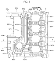
- FIG. 6 is a rear view of the cylinder block provided in the engine of the outboard motor according to the present embodiment.
- FIG. 7 is a top view of the cylinder block provided in the engine of the outboard motor according to the present embodiment.
- FIG. 8 is a perspective view of the periphery of the cylinder block provided in the engine of the outboard motor according to the present embodiment
- FIG. 9 is a cross-sectional view of the exhaust passage on the periphery of the cylinder block provided in the engine of the outboard motor according to the present embodiment.
- FIG. 10 is a left side view illustrating a schematic configuration of the outboard motor according to the present embodiment.
- FIG. 1 is a left side view illustrating a schematic configuration of an outboard motor 1 as a ship propulsion device according to the present embodiment.
- FIG. 2 is a top view illustrating the schematic configuration of the outboard motor 1 according to the present embodiment.
- arrow Fr indicates the front of the outboard motor 1
- arrow Rr indicates the rear of the outboard motor 1
- arrow L indicates the left side of the outboard motor 1
- arrow R indicates the right side of the outboard motor 1 .
- the outboard motor 1 includes: an outboard motor body 2 in which a driving force generated by a mounted engine 21 is transmitted to a propeller 22 to generate a propulsion force; and an attachment bracket device 3 for attaching the outboard motor body 2 to a stern (transom) 100 of a hull.
- the outboard motor body 2 has the engine 21 mounted in the upper portion and is able to drive the propeller 22 in the lower portion.
- the engine 21 for example, a multi-cylinder engine such as a parallel four-cylinder engine can be employed.
- the entire outboard motor body 2 is covered with an exterior cover.
- the engine 21 is covered with an engine cover 4 that is an exterior.
- the engine cover 4 is configured by integral coupling of an engine cover 4 A constituting an upper cover that covers the upper circumference of the engine 21 and an engine cover 4 B constituting a lower cover. With such an engine cover 4 , an engine room that houses the engine 21 has a sealed structure and is blocked from the outside air.
- the attachment bracket device 3 includes a clamp bracket 31 and a swivel bracket 32 .
- the clamp bracket 31 is provided detachably at the stern 100 of the hull.
- the swivel bracket 32 supports the outboard motor body 2 in a horizontally swingable manner and supports the outboard motor body 2 in a perpendicularly swingable manner with respect to the clamp bracket 31 via a swivel shaft 33 .
- the outboard motor body 2 is attached to the hull while being swingable in each of the horizontal direction (steering direction) and the perpendicular direction (tilt direction).
- the engine 21 is mounted vertically so that crankshaft 23 faces the perpendicular direction.
- the crankshaft 23 is coupled with a drive shaft 24 .
- the propeller 22 is attached to one end (rear end) of a propeller shaft 25 . With this configuration, the rotational force of the engine 21 is transmitted to the propeller shaft 25 via the drive shaft 24 , and the propeller 22 rotates forwardly or reversely. This gives the hull a propulsion force on the forward or reverse side.
- crankcase 5 At the foremost (bow) of the engine 21 , a crankcase 5 is disposed.
- a cylinder block 6 is disposed behind the crankcase 5
- a cylinder head 7 is disposed behind the cylinder block 6 (cf. FIG. 2 ).
- the crankshaft 23 is disposed such that its shaft center is located between the crankcase 5 and the cylinder block 6 (more specifically, on the mating surface of the crankcase 5 and the cylinder block 6 ).
- the outboard motor 1 is configured to enable the utilization of the engine 21 for a catalyst-equipped model and a non-catalyst-equipped model depending on the usage environment without the need for a large-scale change.
- selectively usable exhaust passages are formed in the cylinder block 6 , and an exhaust passage to be used is selected in accordance with whether the catalyst is equipped.
- the configuration of the engine 21 will be described below with a focus on the cylinder block 6 .
- FIGS. 3 and 4 are a perspective view and a cross-sectional view, respectively, of the cylinder block 6 including peripheral components provided in the engine 21 of the outboard motor 1 according to the present embodiment.
- FIGS. 3 and 4 illustrate the form of the cylinder block 6 to be utilized for the catalyst-equipped model. Specifically, a case is illustrated where a bypass member 8 which is separate component from the cylinder block 6 has been coupled to the cylinder block 6 .
- FIG. 4 illustrates a cross section through an exhaust passage formed in the cylinder block 6 (first exhaust passage EP 1 to be described later) and an exhaust passage formed in the bypass member 8 (fifth exhaust passage EP 5 to be described later).
- FIGS. 5, 6 and 7 are a front view, a rear view, and a top view, respectively, of the cylinder block 6 provided in the engine 21 of the outboard motor 1 according to the present embodiment.
- FIG. 5 illustrates the mating surface with the crankcase 5 in the cylinder block 6
- FIG. 6 illustrates the mating surface with the cylinder head 7 in the cylinder block 6 .
- the cylinder block 6 constituting the engine 21 is manufactured by die casting.
- the cylinder block 6 can be manufactured inexpensively as compared to a case where the cylinder block 6 is manufactured by low-pressure casting.
- a plurality of spaces formed in the cylinder block 6 e.g., a space 603 a and spaces 604 a to 604 c to be described later
- a core silicor core
- cylinders 601 a to 601 d are formed vertically side by side on the right side of the cylinder block 6 .
- Each of the cylinders 601 a to 601 d is disposed such that its center extends in the front-rear direction and is provided through the cylinder block 6 .
- Each of the cylinders 601 a to 601 d houses a piston (not illustrated).
- the piston is configured to be capable of reciprocation in the front-rear direction in each of the cylinders 601 a to 601 d in accordance with explosion of combustion gas in a combustion chamber (not illustrated) formed in a space with the cylinder head 7 .
- the piston is coupled to the crankshaft 23 via a connection rod (con rod), and the reciprocating motion of the piston is converted into a rotational motion of the crankshaft 23 .
- An exhaust manifold (hereinafter simply referred to as “manifold”) 602 is formed to the left sides of the cylinders 601 a to 601 d (cf. FIGS. 3 and 6 ).
- the manifold 602 is disposed so as to extend in the vertical direction.
- the upper end of the manifold 602 is disposed at a position slightly above the center of the uppermost cylinder 601 a .
- the lower end of the manifold 602 is disposed at a position slightly below than the center of the lowermost cylinder 601 d.
- the manifold 602 is provided by being open on the rear side of the cylinder block 6 . That is, the manifold 602 is provided by being opened on the mating surface side of the cylinder head 7 .
- the manifold 602 communicates to the combustion chamber in the cylinder head 7 via an exhaust hole. Exhaust gas generated in the combustion chamber is discharged to the manifold 602 .
- the manifold 602 includes a linear portion 602 a extending linearly in the vertical direction, and a bent portion 602 b that is connected to the lower end of the linear portion 602 a , is bent diagonally downward to the left, and has a crosswise direction between the inner wall surfaces gradually increasing from the linear portion 602 a (cf. FIG. 6 ).
- an opening 602 c is formed at the front end of the bent portion 602 b .
- the opening 602 c is provided communicating to a space 604 c of a block body 604 to be described later.
- a tubular body 603 extending in the vertical direction (the arrangement direction of the cylinders 601 a to 601 d ) is formed to the left side of the manifold 602 .
- a space 603 a is formed inside the tubular body 603 (cf. FIG. 4 ).
- An opening 603 b is formed on the upper surface of the cylinder block 6 (cf. FIG. 7 ).
- the space 603 a in the tubular body 603 is provided communicating to the opening 603 b .
- a flange portion 603 c is formed around the opening 603 b on the upper surface of the cylinder block 6 .
- the flange portion 603 c is utilized for joining with a flange portion 81 d of a first bypass member 81 to be described later.
- the block body 604 which generally has a rectangular shape is formed below the tubular body 603 .
- the block body 604 is disposed in a position corresponding to the bent portion 602 b of the manifold 602 in the rear view (cf. FIG. 6 ).
- Three spaces 604 a , 604 b , 604 c are formed inside the block body 604 .
- the spaces 604 a , 604 b , 604 c are formed toward respectively different directions in the block body 604 .
- the spaces 604 a , 604 b , 604 c are provided being open on the front side, the lower side, and the left side of the cylinder block 6 , respectively.
- the space 604 a is provided on the front side of the block body 604 , and is formed such that its center extends in the front-rear direction (the longitudinal direction of the cylinders 601 a to 601 d ).
- An opening 604 d is formed on the front surface of the block body 604 (cf. FIG. 5 ).
- the space 604 a is provided communicating to the opening 604 d .
- the space 604 a extends to a rear-side inner wall 604 h in the block body 604 .
- the space 604 b is provided on the lower side of the block body 604 , and is formed such that its center extends in the vertical direction.
- An opening 604 e is formed on the lower surface of the block body 604 .
- the space 604 b is provided communicating to the opening 604 e .
- the space 604 b is provided below the space 604 a .
- a dashed line L indicates the boundary portion of the space 604 a and the space 604 b .
- the rear-side portion of the space 604 a and the upper-side portion of the space 604 b are provided continuously. Thereby, the space 604 a and the space 604 b communicate to each other.
- the space 604 b is configured to extend to the side opposite to (below) the space 603 a across the space 604 a (lower side).
- the space 604 c is provided on the left side of the block body 604 , and is formed such that its center extends in the crosswise direction.
- An opening 604 f is formed on the left side surface of the block body 604 .
- the space 604 c is provided communicating to the opening 604 f.
- the tubular body 603 is disposed above the right-side end of the space 604 c (cf. FIG. 4 ).
- a dashed line indicates a position where the space 604 c is provided.
- the space 604 c is provided continuously with the space 603 a in the tubular body 603 .
- the manifold 602 is provided rearward of the right-side end of the space 604 c .
- the space 604 c is provided continuously with the space in the manifold 602 . Thereby, the space 604 c communicates with the space 603 a and the space constituting the manifold 602 .
- a partition wall 605 is provided to separate these spaces.
- the space 604 c and the space 604 a are provided adjacent to each other across the partition wall 605 .
- the partition wall 605 has a thin portion 605 a in its rear-side portion, and has an arc-shaped portion 605 b continuously to the front side of the thin portion 605 a .
- the thin portion 605 a is provided in a position corresponding to the space 604 b (i.e., above the space 604 b ).
- the arc-shaped portion 605 b serves to induce the exhaust gas having flowed from the manifold 602 side to the space 603 a side.
- the bypass member 8 is disposed forward of the tubular body 603 and the block body 604 .
- the bypass member 8 is disposed so as to extend in the vertical direction while extending in the front-rear direction of the cylinder block 6 . Disposing the bypass member 8 in this manner can prevent an increase in the dimension of the cylinder block 6 (engine 21 ) in the width direction (crosswise direction).
- the bypass member 8 is manufactured by, for example, die casting or low-pressure casting.
- the bypass member 8 generally has a U-shape being open on the rear side, or a shape formed by vertically reversing a J-shape.
- the bypass member 8 has a first bypass member 81 and a second bypass member 82 that are made up of a pair of tubular bodies.
- the bypass member 8 is made up of the pair of tubular bodies.
- the configuration of the bypass member 8 is not limited thereto but can be changed as appropriate.
- the bypass member 8 may be made of a single member.
- the first bypass member 81 is disposed such that its center extends in the front-rear direction.
- the first bypass member 81 generally has an L-shape in a top view (cf. FIG. 2 ). As illustrated in FIG. 4 , the front-side end and the rear-side end of the first bypass member 81 each have a configuration to be slightly bent downward.
- the second bypass member 82 is generally disposed such that its center extends in the vertical direction. The lower end of the second bypass member 82 has a configuration to be bent rearward.
- a space 81 a is formed inside the first bypass member 81 .
- Openings 81 b , 81 c are formed on the lower sides of the front-side end and the rear-side end of the first bypass member 81 (cf. FIG. 4 ).
- the space 81 a is provided communicating to these openings 81 b , 81 c .
- Flange portions 81 d , 81 e are provided around the openings 81 b , 81 c , respectively (cf. FIG. 3 ).
- the first bypass member 81 is coupled to the upper end of the tubular body 603 so as to communicate to the space 603 a via the opening 81 b .
- the first bypass member 81 and the tubular body 603 are joined by fastening the flange portion 81 d and the flange portion 603 c with a screw.
- a space 82 a is formed inside the second bypass member 82 .
- An opening 82 b is formed at the upper-side end of the second bypass member 82 .
- the space 82 a is provided communicating to the opening 82 b .
- the second bypass member 82 is coupled to the lower side of the first bypass member 81 so as to communicate to the space 81 a via the opening 82 b .
- a flange portion 82 d is provided around the opening 82 b (cf. FIG. 3 ).
- the second bypass member 82 and the first bypass member 81 are joined by fastening the flange portion 82 d and the flange portion 81 d with a screw.
- an opening 82 c is formed at the rear of the lower-side end of the second bypass member 82 (cf. FIG. 4 ).
- the space 82 a is provided communicating to the opening 82 c .
- the second bypass member 82 is coupled to the front side of the block body 604 so as to communicate to the space 604 a via the opening 82 c .
- a flange portion 82 e is provided around the opening 82 c (cf. FIG. 3 ).
- the second bypass member 82 and the block body 604 are joined by fastening the flange portion 82 e and a flange portion 604 g of the block body 604 with a screw.
- the exhaust passages in the engine 21 according to the present embodiment will be described.
- the space 603 a in the tubular body 603 constitutes a first exhaust passage EP 1 .
- the first exhaust passage EP 1 extends in the arrangement direction of the cylinders 601 a to 601 d (vertical direction) and has an opening end made of an opening 603 b.
- the space 604 a in the block body 604 constitutes a second exhaust passage EP 2
- the space 604 b constitutes a third exhaust passage EP 3
- the space 604 c constitutes a fourth exhaust passage EP 4
- the second exhaust passage EP 2 extends in the longitudinal direction of the cylinders 601 a to 601 d (front-rear direction) and has an opening end made of an opening 604 d .
- the fourth exhaust passage EP 4 is provided extending in the direction orthogonal to both the first exhaust passage EP 1 and the second exhaust passage EP 2 .
- the space 81 a in the first bypass member 81 and the space 82 a in the second bypass member 82 constitute a fifth exhaust passage EP 5 .
- the fourth exhaust passage EP 4 is provided in the coupling portion of the manifold 602 and the first exhaust passage EP 1 .
- the fourth exhaust passage EP 4 is configured separately from the first exhaust passage EP 1 in order to form on the inner wall a curved surface that induces the exhaust gas having flowed from the manifold 602 to the first exhaust passage EP 1 side.
- a curved surface is formed by utilizing a core for forming the space 603 a constituting the first exhaust passage EP 1 or the space constituting the manifold 602 , a situation may occur in which a smooth curved surface cannot be formed in the corner portion, thus causing a decrease in the exhaust efficiency in the exhaust passage.
- a dedicated core for forming the curved surface as in the present embodiment, it is possible to form a desired curved surface in the corner portion and improve the exhaust efficiency in the exhaust passage.
- a cooling channel is formed to allow the flow of cooling water utilized for cooling the exhaust gas.
- a cooling channel WP 1 is formed around the manifold 602 (cf. FIG. 3 ).
- a cooling channel WP 2 is formed around the space 603 a constituting the first exhaust passage EP 1 (cf. FIG. 4 ).
- a cooling channel WP 3 is formed around the spaces 604 a , 604 b constituting the second exhaust passage EP 2 and the third exhaust passage EP 3 .
- a cooling channel WP 4 is also formed around the cylinders 601 a to 601 d (cf. FIG. 3 ).
- a cooling channel WP 5 is formed around the spaces 81 a , 82 a constituting the fifth exhaust passage EP 5 .
- a first catalyst unit 91 is housed in the space 603 a constituting the first exhaust passage EP 1
- a second catalyst unit 92 is housed in the space 82 a constituting the fifth exhaust passage EP 5
- the first catalyst unit 91 includes a catalyst holder 911 and a catalyst 912 held in the catalyst holder 911 .
- the first catalyst unit 91 includes a pair of catalysts 912 .
- the catalyst holder 911 holds the catalyst 912 so that the catalyst 912 is disposed on the first exhaust passage EP 1 .
- the second catalyst unit 92 includes a catalyst holder 921 and a catalyst 922 held in the catalyst holder 921 .
- the catalyst holder 921 holds the catalyst 922 so that the catalyst 922 is disposed on the fifth exhaust passage EP 5 .
- the first catalyst unit 91 with respect to the first exhaust passage EP 1 is configured so as to be detachable from the upper side of the cylinder block 6 .
- Such a detachable configuration makes it possible to improve work efficiency during maintenance for the catalyst unit housed in the cylinder block 6 .
- the description has been given of the case where the catalyst units are disposed in the first exhaust passage EP 1 and the fifth exhaust passage EP 5 .
- the catalyst unit may be disposed in either one of the exhaust passages depending on the purification performance required.
- the exhaust gas from the cylinders 601 a to 601 d flows into the manifold 602 via the cylinder head 7 . Then, the exhaust gas having flowed into the manifold 602 proceeds downward along the linear portion 602 a and flows into the fourth exhaust passage EP 4 via the opening 602 c . The exhaust gas having flowed into the fourth exhaust passage EP 4 turns its flow direction upward along the inner wall surface of the fourth exhaust passage EP 4 and proceeds upward along the first exhaust passage EP 1 .
- the exhaust gas is purified by the first catalyst unit 91 when flowing upward along the first exhaust passage EP 1 .
- the opening 604 f of the space 604 c constituting the fourth exhaust passage EP 4 is closed by a plate P 1 (cf. FIG. 1 ).
- the plate P 1 is fixed to the block body 604 so as to close the opening 604 f from the left side. Therefore, during the operation of the engine 21 , the exhaust gas having flowed from the manifold 602 into the fourth exhaust passage EP 4 does not flow out from the opening 604 f.
- the exhaust gas having passed through the first exhaust passage EP 1 flows into the fifth exhaust passage EP 5 formed in the space 81 a and proceeds forward.
- the exhaust gas turns its flow direction downward and proceeds downward along the fifth exhaust passage EP 5 formed in the space 82 a .
- the exhaust gas is purified by the second catalyst unit 92 when proceeding downward along the fifth exhaust passage EP 5 formed in the space 82 a .
- the exhaust gas having flown into the vicinity of the lower end of the fifth exhaust passage EP 5 turns its flow direction rearward along the inner wall surface of the fifth exhaust passage EP 5 and flows into the second exhaust passage EP 2 .
- the exhaust gas having flowed into the second exhaust passage EP 2 turns its flow direction downward and proceeds downward along the third exhaust passage EP 3 .
- the exhaust gas flows into an exhaust passage (not illustrated) formed in an engine base below the cylinder block 6 .
- FIGS. 8 and 9 are a perspective view and a cross-sectional view, respectively, of the cylinder block 6 provided in the engine 21 of the outboard motor 1 according to the present embodiment.
- FIG. 9 illustrates a cross-section through the exhaust passage (first exhaust passage EP 1 ) formed in the cylinder block 6 .
- FIG. 10 is a left side view illustrating the schematic configuration of the outboard motor 1 according to the present embodiment.
- the bypass member 8 is not attached to the cylinder block 6 .
- the opening 603 b of the tubular body 603 and the opening 604 d of the block body 604 , to which the bypass member 8 has attached, are closed by plates P 2 , P 3 , respectively.
- the plate P 2 is fixed with a screw from the upper side of the cylinder block 6 to the flange portion 603 c of the tubular body 603 .
- the plate P 3 is fixed with a screw from the front side of the cylinder block 6 to the flange portion 604 g of the block body 604 .
- the catalyst holder 911 and a plug PG 1 are housed in the space 603 a communicating to the opening 603 b .
- the plug PG 1 is provided in the space 603 a while pressed downward via the catalyst holder 911 .
- the lower-side end of the plug PG 1 extends to a position facing the space 604 c that constitutes the fourth exhaust passage EP 4 .
- the plug PG 1 may be changed in shape and directly fixed by the plate P 2 .
- the catalyst holder 911 and the plug PG 1 occupy substantially the entire area of the space 603 a constituting the first exhaust passage EP 1 . This significantly reduces volumes in the space 604 c and the space 603 a .
- a recess having a hemispherical shape is formed on the lower surface of the plug PG 1 . The recess serves to induce the exhaust gas, having flowed into the fourth exhaust passage EP 4 via the manifold 602 , to the third exhaust passage EP 3 provided on the lower side.
- a plug PG 2 is housed in the space 604 a communicating to the opening 604 d .
- the plug PG 2 is provided in the space 604 a while pressed rearward by the plate P 3 .
- the rear-side end of the plug PG 2 extends to the vicinity of the center of the space 604 a constituting the second exhaust passage EP 2 .
- the plug PG 2 occupies a part of the entire front side of the space 604 a constituting the second exhaust passage EP 2 . This significantly reduces volumes in the space 604 a and the space 604 b.
- the partition wall 605 between the space 604 a constituting the second exhaust passage EP 2 and the space 604 c constituting the fourth exhaust passage EP 4 (cf. FIG. 4 ) is removed.
- the partition wall 605 is removed by machining.
- a communication hole 605 c is formed. Through this communication hole 605 c , the space 604 a (second exhaust passage EP 2 ) and the space 604 c (fourth exhaust passage EP 4 ) communicate to each other.
- the communication hole 605 c is formed in a position corresponding to the thin portion 605 a (cf. FIG.
- the communication hole 605 c By forming the communication hole 605 c in the position corresponding to the thin portion 605 a , the communication hole 605 c can be provided on the extension line of the space 604 b (third exhaust passage EP 3 ), and the exhaust gas having flowed into the fourth exhaust passage EP 4 via the manifold 602 can be allowed to efficiently flow into the third exhaust passage EP 3 .
- the exhaust gas from the cylinders 601 a to 601 d flows into the manifold 602 via the cylinder head 7 . Then, the exhaust gas having flowed into the manifold 602 proceeds downward along the linear portion 602 a and flows into the fourth exhaust passage EP 4 via the opening 602 c . As described above, the catalyst holder 911 and plug PG 1 occupy the first exhaust passage EP 1 . Meanwhile, the fourth exhaust passage EP 4 and the second exhaust passage EP 2 communicate via the communication hole 605 c . Hence the exhaust gas having flowed into the fourth exhaust passage EP 4 turns its flow direction downward and flows into the second exhaust passage EP 2 . Then, the exhaust gas proceeds downward along the third exhaust passage EP 3 via the second exhaust passage EP 2 and flows into the exhaust passage (not illustrated) formed below of the cylinder block 6 .
- the raw blank of the cylinder block 6 can be used for both of the following two exhaust routes: a route (first exhaust route) in which, when the engine 21 is to be utilized for the catalyst-equipped model, the exhaust gas proceeds from the fourth exhaust passage EP 4 to the first exhaust passage EP 1 , and is allowed to flow along the second exhaust passage EP 2 and the third exhaust passage EP 3 via the fifth exhaust passage EPS; and a route (second exhaust route) in which, when the engine 21 is to be utilized for the non-catalyst-equipped model, the exhaust gas is allowed to flow from the fourth exhaust passage EP 4 to the second exhaust passage EP 2 and the third exhaust passage EP 3 , and one of the first exhaust route and the second exhaust route is selected to be used as the exhaust passage.
- a route first exhaust route
- second exhaust route in which, when the engine 21 is to be utilized for the non-catalyst-equipped model, the exhaust gas is allowed to flow from the fourth exhaust passage EP 4 to the second exhaust passage EP 2 and the third exhaust passage EP 3 , and one of the first exhaust route and
- the exhaust passages (first to fourth exhaust passages EP 1 to EP 4 ) formed in the cylinder block 6 it is possible to achieve the engine 21 for the catalyst-equipped model and the non-catalyst-equipped model without the need for a large-scale change. Further, with the exhaust passages (first to fourth exhaust passages EP 1 to EP 4 ) being formed in the cylinder block 6 , the manufacturing can be facilitated as compared to the case of forming the exhaust passages in the cylinder head and the exhaust manifold that are generally manufactured by low-pressure casting.
- first catalyst unit 91 being disposed in the exhaust passage (first exhaust passage EP 1 ) in the cylinder block 6 , it is possible to reduce the restriction on the upper limit of the size of the catalyst 912 and ensure the exhaust-gas purifying performance as compared to a case where the catalyst unit is disposed in the exhaust manifold.
- the opening 603 b (the opening end of the first exhaust passage EP 1 ) and the opening 604 d (the opening end of the second exhaust passage EP 2 ) of the cylinder block 6 are coupled by the fifth exhaust passage EP 5 in the bypass member 8 to form a part of the first exhaust route, and the catalyst unit (first catalyst unit 91 , second catalyst unit 92 ) is disposed in the exhaust passage of the first exhaust route.
- the catalyst unit since it is possible to utilize the engine 21 for the catalyst-equipped model only by attaching the bypass member 8 to the cylinder block 6 .
- the catalyst unit is disposed in the exhaust passage of the first exhaust route formed by attaching the bypass member 8 to the cylinder block 6 , it is possible to make the arrangement of the catalyst unit flexible and ensure the size of the catalyst to be placed in the exhaust passage.
- the fifth exhaust passage EP 5 in the bypass member 8 is provided so as to extend in the longitudinal direction of the plurality of cylinders 601 a to 601 d (front-rear direction) and the arrangement direction of the plurality of cylinders 601 a to 601 d (vertical direction). Disposing the fifth exhaust passage EP 5 in this manner can prevent an increase in the dimension of the engine 21 (cylinder block 6 ) in the width direction (crosswise direction).
- the fifth exhaust passage EP 5 has a U-shape or a J-shape to allow the exhaust gas to flow in the longitudinal direction of the plurality of cylinders (front-rear direction) and the arrangement direction of the plurality of cylinders (vertical direction). Constituting the fifth exhaust passage EP 5 in this manner enables the coupling between the opening end (opening 603 b ) of the first exhaust passage EP 1 and the opening end (opening 604 d ) of the second exhaust passage EP 2 in a simple configuration.
- the third exhaust passage EP 3 is communicated with the exhaust passage formed outside (below) the cylinder block 6 , and the exhaust gas is discharged from the third exhaust passage EP 3 to the outside of the cylinder block 6 .
- the exhaust gas can be discharged outside the cylinder block 6 in a simple configuration.
- the opening ends of the first exhaust passage EP 1 and the second exhaust passage EP 2 are closed while the communication hole 605 c is provided in the partition wall 605 formed between the fourth exhaust passage EP 4 and the second exhaust passage EP 2 , to be used as the exhaust passage of the second exhaust route. Therefore, only by performing simple processing (e.g., machining), the exhaust passage of the second exhaust route can be configured utilizing some of the exhaust passages to be utilized for the catalyst-equipped model (from the fourth exhaust passage EP 4 to the second exhaust passage EP 2 and the third exhaust passage EP 3 ). As a result, it is possible to achieve the non-catalyst-equipped model while reducing the manufacturing cost.
- the plugs PG 1 , PG 2 are provided in the recesses (space 603 a and space 604 a ) formed in the cylinder block 6 to reduce the volume.
- the utilization form of the cylinder block 6 in the case of the utilization for the non-catalyst-equipped model is not limited thereto but can be changed as appropriate.
- the recess in the cylinder block 6 may be left to be utilized as a resonant device (resonator).
- resonator resonant device
- the present invention is not limited to the above embodiment but can be subjected to various changes and then implemented.
- the sizes and shapes illustrated in the accompanying drawings are not limited thereto but can be changed as appropriate within a scope in which the effect of the present invention is exerted.
- the other elements can be changed as appropriate and implemented so long as not deviating from the scope of the object of the present invention.
- the present invention is applied to the outboard motor 1 including the parallel four-cylinder engine.
- an application target of the present invention is not limited thereto but can be changed as appropriate.
- bypass member 8 has the configuration to be disposed forward of the tubular body 603 and the block body 604 , extending in the front-rear direction and the vertical direction of the cylinder block 6 .
- the configuration of the bypass member 8 is not limited thereto but can be changed as appropriate.
- the bypass member 8 may be configured to extend in the crosswise direction of the cylinder block 6 in accordance with the entire shape of the engine mounted on the outboard motor 1 .
- bypass member 8 has a U-shape or a J-shape in the side view
- any shape may be employed in accordance with the position of the opening end of the first exhaust passage EP 1 and the opening end of the second exhaust passage EP 2 formed in the cylinder block 6 .
- the present invention has the effect of being able to ensure sufficient exhaust-gas purifying performance without the need for a complex manufacturing process and achieve an engine for the catalyst-equipped model and the non-catalyst-equipped model without the need for a large-scale change.
- the present invention is useful for a ship propulsion device having the catalyst-equipped model and the non-catalyst-equipped model.
Landscapes
- Engineering & Computer Science (AREA)
- Chemical & Material Sciences (AREA)
- Combustion & Propulsion (AREA)
- Mechanical Engineering (AREA)
- General Engineering & Computer Science (AREA)
- Ocean & Marine Engineering (AREA)
- Exhaust Silencers (AREA)
Abstract
Description
- outboard motor
- crankcase
- cylinder block
- cylinder head
- bypass member
- engine
- first bypass member
- 81 a space
- 81 b opening
- 81 c opening
- 82 second bypass member
- 82 a space
- 82 b opening
- 82 c opening
- 91 first catalyst unit
- 911 catalyst holder
- 912 catalyst
- 92 second catalyst unit
- 921 catalyst holder
- 922 catalyst
- 601 a to 601 d cylinder
- 602 manifold
- 602 c opening
- 603 tubular body
- 603 a space
- 603 b opening
- 604 block body
- 604 a to 604 c space
- 604 d to 604 f opening
- 605 partition wall
- 605 c communication hole
- EP1 first exhaust passage
- EP2 second exhaust passage
- EP3 third exhaust passage
- EP4 fourth exhaust passage
- EP5 fifth exhaust passage
- P1 to P3 plate
- PG1, PG2 plug
Claims (6)
Applications Claiming Priority (3)
| Application Number | Priority Date | Filing Date | Title |
|---|---|---|---|
| JPJP2019-110092 | 2019-06-13 | ||
| JP2019110092A JP2020200816A (en) | 2019-06-13 | 2019-06-13 | Ship propulsion device |
| JP2019-110092 | 2019-06-13 |
Publications (2)
| Publication Number | Publication Date |
|---|---|
| US20200392894A1 US20200392894A1 (en) | 2020-12-17 |
| US11131239B2 true US11131239B2 (en) | 2021-09-28 |
Family
ID=73743924
Family Applications (1)
| Application Number | Title | Priority Date | Filing Date |
|---|---|---|---|
| US16/897,253 Active US11131239B2 (en) | 2019-06-13 | 2020-06-09 | Ship propulsion device |
Country Status (2)
| Country | Link |
|---|---|
| US (1) | US11131239B2 (en) |
| JP (1) | JP2020200816A (en) |
Families Citing this family (1)
| Publication number | Priority date | Publication date | Assignee | Title |
|---|---|---|---|---|
| JP2024064613A (en) * | 2022-10-28 | 2024-05-14 | ヤマハ発動機株式会社 | Marine propulsion equipment |
Citations (5)
| Publication number | Priority date | Publication date | Assignee | Title |
|---|---|---|---|---|
| US6632110B2 (en) * | 2000-04-13 | 2003-10-14 | Yamaha Marine Kabushiki Kaisha | Exhaust catalyst for outboard motor engine |
| US6884133B2 (en) * | 2000-06-12 | 2005-04-26 | Yamaha Marine Kabushiki Kaisha | Catalyzer arrangement for outboard motor |
| JP2012159062A (en) | 2011-02-02 | 2012-08-23 | Yamaha Motor Co Ltd | Outboard motor and method for manufacturing the same |
| US9869228B2 (en) * | 2015-01-30 | 2018-01-16 | Suzuki Motor Corporation | Exhaust passage structure of outboard motor |
| US10876459B1 (en) * | 2018-01-31 | 2020-12-29 | Brp Us Inc. | Exhaust system for a marine outboard engine |
-
2019
- 2019-06-13 JP JP2019110092A patent/JP2020200816A/en active Pending
-
2020
- 2020-06-09 US US16/897,253 patent/US11131239B2/en active Active
Patent Citations (7)
| Publication number | Priority date | Publication date | Assignee | Title |
|---|---|---|---|---|
| US6632110B2 (en) * | 2000-04-13 | 2003-10-14 | Yamaha Marine Kabushiki Kaisha | Exhaust catalyst for outboard motor engine |
| US6884133B2 (en) * | 2000-06-12 | 2005-04-26 | Yamaha Marine Kabushiki Kaisha | Catalyzer arrangement for outboard motor |
| JP2012159062A (en) | 2011-02-02 | 2012-08-23 | Yamaha Motor Co Ltd | Outboard motor and method for manufacturing the same |
| US20130029545A1 (en) | 2011-02-02 | 2013-01-31 | Yamaha Hatsudoki Kabushiki Kaisha | Outboard motor and method for manufacturing outboard motor |
| US8814619B2 (en) | 2011-02-02 | 2014-08-26 | Yamaha Hatsudoki Kabushiki Kaisha | Outboard motor and method for manufacturing outboard motor |
| US9869228B2 (en) * | 2015-01-30 | 2018-01-16 | Suzuki Motor Corporation | Exhaust passage structure of outboard motor |
| US10876459B1 (en) * | 2018-01-31 | 2020-12-29 | Brp Us Inc. | Exhaust system for a marine outboard engine |
Also Published As
| Publication number | Publication date |
|---|---|
| JP2020200816A (en) | 2020-12-17 |
| US20200392894A1 (en) | 2020-12-17 |
Similar Documents
| Publication | Publication Date | Title |
|---|---|---|
| US7641527B1 (en) | Marine outboard engine exhaust system | |
| US11131239B2 (en) | Ship propulsion device | |
| JP6384395B2 (en) | Outboard motor | |
| US10036299B2 (en) | Exhaust apparatus of outboard motor | |
| JP4446303B2 (en) | Outboard motor | |
| US3052086A (en) | Tuned exhaust for outboard motors | |
| JP3695232B2 (en) | Outboard motor exhaust system | |
| JP4780441B2 (en) | Outside air intake structure of outboard motor | |
| JP3999906B2 (en) | Engine mount structure for small marine engine | |
| JP4269026B2 (en) | Outboard motor intake system | |
| US7047732B2 (en) | Outboard engine exhaust structure | |
| JP4788458B2 (en) | Outboard motor intake system | |
| US9869228B2 (en) | Exhaust passage structure of outboard motor | |
| JP7169385B2 (en) | Intake passage structure | |
| JP5171092B2 (en) | Exhaust system in outboard motor | |
| JPH1191684A (en) | Hydroplane | |
| US7523735B2 (en) | Multiple-cylinder engine for outboard motor | |
| JPH0667757B2 (en) | Outboard engine | |
| JP2822178B2 (en) | Exhaust system for personal watercraft | |
| JPH0540262Y2 (en) | ||
| JP6406042B2 (en) | Outboard motor | |
| JPH09236015A (en) | Exhaust system for small planing boats | |
| JP3340220B2 (en) | Exhaust system for outboard engine | |
| JP2008144681A (en) | Outboard motor exhaust system | |
| JP2000257423A (en) | Water-cooled engine cooling structure |
Legal Events
| Date | Code | Title | Description |
|---|---|---|---|
| AS | Assignment |
Owner name: SUZUKI MOTOR CORPORATION, JAPAN Free format text: ASSIGNMENT OF ASSIGNORS INTEREST;ASSIGNORS:KISHIMOTO, MORIO;SUZUKI, CHIAKI;ITO, JUN;REEL/FRAME:052886/0947 Effective date: 20200313 |
|
| FEPP | Fee payment procedure |
Free format text: ENTITY STATUS SET TO UNDISCOUNTED (ORIGINAL EVENT CODE: BIG.); ENTITY STATUS OF PATENT OWNER: LARGE ENTITY |
|
| STPP | Information on status: patent application and granting procedure in general |
Free format text: APPLICATION DISPATCHED FROM PREEXAM, NOT YET DOCKETED |
|
| STPP | Information on status: patent application and granting procedure in general |
Free format text: DOCKETED NEW CASE - READY FOR EXAMINATION |
|
| STPP | Information on status: patent application and granting procedure in general |
Free format text: NOTICE OF ALLOWANCE MAILED -- APPLICATION RECEIVED IN OFFICE OF PUBLICATIONS |
|
| STPP | Information on status: patent application and granting procedure in general |
Free format text: PUBLICATIONS -- ISSUE FEE PAYMENT VERIFIED |
|
| STCF | Information on status: patent grant |
Free format text: PATENTED CASE |
|
| MAFP | Maintenance fee payment |
Free format text: PAYMENT OF MAINTENANCE FEE, 4TH YEAR, LARGE ENTITY (ORIGINAL EVENT CODE: M1551); ENTITY STATUS OF PATENT OWNER: LARGE ENTITY Year of fee payment: 4 |