US11115573B2 - Hyperspectral plenoptic camera - Google Patents
Hyperspectral plenoptic camera Download PDFInfo
- Publication number
- US11115573B2 US11115573B2 US16/413,231 US201916413231A US11115573B2 US 11115573 B2 US11115573 B2 US 11115573B2 US 201916413231 A US201916413231 A US 201916413231A US 11115573 B2 US11115573 B2 US 11115573B2
- Authority
- US
- United States
- Prior art keywords
- wavelengths
- filter
- plenoptic camera
- plenoptic
- camera
- Prior art date
- Legal status (The legal status is an assumption and is not a legal conclusion. Google has not performed a legal analysis and makes no representation as to the accuracy of the status listed.)
- Expired - Fee Related, expires
Links
Images


Classifications
-
- H04N5/2254—
-
- H—ELECTRICITY
- H04—ELECTRIC COMMUNICATION TECHNIQUE
- H04N—PICTORIAL COMMUNICATION, e.g. TELEVISION
- H04N23/00—Cameras or camera modules comprising electronic image sensors; Control thereof
- H04N23/95—Computational photography systems, e.g. light-field imaging systems
- H04N23/957—Light-field or plenoptic cameras or camera modules
-
- H—ELECTRICITY
- H04—ELECTRIC COMMUNICATION TECHNIQUE
- H04N—PICTORIAL COMMUNICATION, e.g. TELEVISION
- H04N23/00—Cameras or camera modules comprising electronic image sensors; Control thereof
- H04N23/50—Constructional details
- H04N23/55—Optical parts specially adapted for electronic image sensors; Mounting thereof
-
- G—PHYSICS
- G02—OPTICS
- G02B—OPTICAL ELEMENTS, SYSTEMS OR APPARATUS
- G02B27/00—Optical systems or apparatus not provided for by any of the groups G02B1/00 - G02B26/00, G02B30/00
- G02B27/09—Beam shaping, e.g. changing the cross-sectional area, not otherwise provided for
- G02B27/0938—Using specific optical elements
- G02B27/095—Refractive optical elements
- G02B27/0955—Lenses
- G02B27/0961—Lens arrays
-
- G—PHYSICS
- G02—OPTICS
- G02B—OPTICAL ELEMENTS, SYSTEMS OR APPARATUS
- G02B5/00—Optical elements other than lenses
- G02B5/20—Filters
-
- H—ELECTRICITY
- H04—ELECTRIC COMMUNICATION TECHNIQUE
- H04N—PICTORIAL COMMUNICATION, e.g. TELEVISION
- H04N23/00—Cameras or camera modules comprising electronic image sensors; Control thereof
- H04N23/50—Constructional details
- H04N23/54—Mounting of pick-up tubes, electronic image sensors, deviation or focusing coils
-
- H04N5/2253—
Definitions
- the present disclosure generally relates to imaging devices and more particularly to multi-spectral imaging devices.
- Consumer off-the-shelf cameras typically include an array of red, green, and blue filters (e.g., Bayer filters) permanently affixed in front of a camera sensor.
- filters e.g., Bayer filters
- Such filter arrays may not be suitable for many scientific applications that require imaging of specific wavelengths of light.
- a Bayer filter array may not transmit the entire spectrum of interest for a given application.
- a particular filter segment (e.g., green) in a Bayer filter array may transmit multiple nearby wavelengths, which are required to be imaged separately.
- Multi-spectral imaging systems may be used in various applications to simultaneously or sequentially capture images at the specific wavelengths of interest.
- Some multi-spectral system use beam splitters or other optical elements to direct light of different wavelength to respective greyscale sensors for imaging. These systems are cumbersome, and quickly grow in size as more wavelengths are added. Accordingly, such systems are typically limited to measurements in a single line of sight.
- Some other multi-spectral imaging systems include filters for different wavelengths on a mechanical disk (called a filter wheel), which is rotated in front in a greyscale sensor to sequentially acquire images at different wavelengths.
- filter-wheel systems present several drawbacks. For example, filter-wheel apparatus are typically bulky and include moving parts, which are subject to failure. Moreover, since the images are taken at different times, data acquisition rate is slowed and imaging of transient events is inhibited.
- a plenoptic camera may comprise a filter, which may be configured to selectively permit transmission of radiated wavelengths (e.g., light).
- the filter may be placed in an aperture plane of the plenoptic camera, e.g., between two or more lenses of the plenoptic camera. Placement of the filter in the aperture plane may mitigate undesirable effects (e.g., image shifting) associated with placing the filter in other locations, such as in front of the aperture plane.
- the filter may transmit discrete frequencies and/or a continuous range of frequencies.
- One or more lenses and/or irises may be present to further focus, collect, or transmit the wavelengths to a micro lens array.
- the lenses may be configured to move with respect to one another and/or with respect to a micro lens array and/or an image sensor to focus the wavelengths.
- the micro lens array may be configured to receive and transmit the filtered wavelengths to an image sensor based on, e.g., an intensity and location of the wavelengths.
- the micro lens array may comprise a plurality of lenses in different locations in a camera, the lenses may differently receive and transmit different portions of an image (e.g., different portions of a two-dimensional image, different portions of a wavelength) to the image sensor.
- the image sensor may receive and process the filtered and focused wavelengths.
- the image sensor and micro lens array may be contained within, e.g., a camera, such that the aperture plane may comprise the filter and one or more lenses external to a commercially-available camera.
- Imaged material(s) may include solid matter as well as fluidic transparent or semitransparent or other absorptive or emitting matter including, for example, a plume of gas, a flame, or a plasma.
- Image data may be generated by a plenoptic camera having a filter configured to transmit light with a plurality of different characteristics (e.g., different wavelengths, polarity, and/or angular perspective) in respective regions of the filter.
- a set of plenoptic image data may be produced by determining respective sets of pixels in the image data corresponding to the different regions of the filter and determining intensities of light with the plurality of different characteristics for respective super-pixel groups of the pixels in the image data.
- One or more additional quantitative measurements of an imaged material may be derived from a comparison of the determined intensities of light of two or more of the plurality of different characteristics.
- An apparatus may be configured to derive quantitative measurements of an imaged material using plenoptic imaging.
- the apparatus may comprise a first processing circuit configured to receive image data from a plenoptic camera, which may comprise a filter configured to transmit light with a plurality of different characteristics in respective a plurality of different spectra in different regions of the filter.
- the first processing circuit may be further configured to, in response to receiving the image data, produce a set of plenoptic image data by determining respective sets of pixels in the image data corresponding to the different regions of the filter and determining light intensities of the plurality of different spectra for respective super-pixel groups in the image data.
- the apparatus may also include a second processing circuit coupled to the first processing circuit.
- the second processing circuit may be configured to derive one or more additional quantitative measurements of an imaged material from a comparison of the determined intensities of light of two or more of the plurality of different characteristics.
- FIG. 1 shows an example plenoptic camera.
- FIG. 2 shows a block diagram of a plenoptic imaging system.
- FIG. 3 shows a block diagram of a process for processing plenoptic image data.
- FIG. 4 shows a block diagram of a process for processing plenoptic image data.
- FIG. 5 shows a block diagram of a plenoptic camera that is reconfigurable for use with various different filters.
- FIG. 6 shows a block diagram of a process for processing a reconfigurable plenoptic camera.
- FIG. 7 shows a computing device that may be used to process sensor data and/or plenoptic image data.
- FIG. 8 shows a plenoptic camera with filters located at an aperture plane.
- FIG. 9 shows a plenoptic camera comprising a plurality of lenses and with filters located at an aperture plane.
- FIG. 10 depicts design rules for a plurality of aperture diameters for a plenoptic camera.
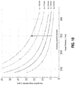
- FIG. 11 shows a graph depicting the relationship between object distance and image distance across a plurality of different focal lengths.
- FIG. 12 shows a graph depicting the relationship between magnification and image distance across a plurality of different focal lengths.
- the terms “upper,” “lower,” “right,” “left,” “rear,” “front,” “vertical,” “horizontal,” and derivatives thereof shall relate to orientation shown in FIG. 1 .
- the disclosed embodiments may assume various alternative orientations and step sequences, except where expressly specified to the contrary.
- the specific devices and processes illustrated in the attached drawings, and described in the following specification are simply exemplary embodiments of the inventive concepts defined in the appended claims. Hence, specific dimensions and other physical characteristics relating to the embodiments disclosed herein are not to be considered as limiting, unless the claims expressly state otherwise.
- the disclosed embodiments are primarily discussed with reference to performing spectral and/or geometric based analysis of plenoptic image data captured by a single plenoptic camera. However, the embodiments are not so limited: some embodiments may perform spectral and/or geometric based analysis on plenoptic image data captured from multiple plenoptic cameras configured as described herein.
- FIG. 1 shows an example plenoptic camera.
- the plenoptic camera includes a filter array 110 having a plurality of different segments 112 , 114 , 116 , 118 , and 120 .
- Each segment of the plurality of different segments 112 , 114 , 116 , 118 , and 120 is configured to pass a respective wavelength of light.
- the filter array 110 may also be referred to as a band-pass filter.
- the segments can be discrete or continuous. For example, each segment may have a uniform transmission bandwidth across the segment with different segments having different, or the same, transmission wavelength.
- the filter may include an infinite number of segments wherein the transmission wavelength continuously varies across a single large filter. Several such continuously variable filters may be placed in this plane.
- the filters themselves may be interference filters, absorptive filters, and/or may be made of a transparent solid material (e.g. glass or quartz), gaseous material (e.g. iodine or mercury vapor), polarization selective elements, Fabry-Perot etalons, and/or Fizeau etalons.
- Neutral density filters can be used to extend the dynamic range of the measurements. Combinations of any of these filters may be used.
- Incident light reflected from a source object 102 may be filtered by the filter array 110 and then passes through a primary lens 130 of the camera.
- Light from the primary lens 130 is focused by an array 140 of secondary lenses 142 .
- the secondary lenses 142 may be implemented with various types of lenses including, for example, pinholes or physical micro-lenses.
- Each secondary lens in the array may focus a projection of the filtered image (e.g., as filtered by filter array 110 ) onto a respective group of pixels of a sensor array 150 .
- Each secondary lens of the secondary lenses 142 may form an image of the filter array 110 onto a respective area of the sensor array 150 .
- Light intensity measurements of cumulative pixels in the sensor array 150 may form a set of raw sensor data 160 .
- the respective group of pixels onto which the filter image is projected by a secondary lens of the array may be referred to as a super-pixel.
- Light filtered by each segment of the filter array 110 may be projected onto a respective subset of pixels of each super pixel. Accordingly, each super pixel may measure light intensity of the different wavelengths at a specific position corresponding to the position of the secondary lens.
- the sensor array 150 may be implemented using various ultraviolet, visible, and/or infrared light sensors for technologies including, but not limited to, charge-coupled device (CCD) sensors and/or complementary metal-oxide semiconductor (CMOS) sensors.
- CCD charge-coupled device
- CMOS complementary metal-oxide semiconductor
- Pixel locations for each of the different wavelengths may be indicated by a pixel map.
- pixel data for each wavelength may be extracted from the raw sensor data 160 to produce a set of plenoptic image data.
- light intensity data for the different wavelengths may be analyzed to derive various quantitative measurements of an imaged material.
- FIG. 2 shows a block diagram of a plenoptic imaging system.
- a system 200 may include a first processing circuit 220 configured to process sensor data generated by a plenoptic camera 210 to produce a set of plenoptic image data.
- the first processing circuit 220 may utilize various processes to generate the plenoptic image data.
- Block 240 shows a process that may be utilized by the processing circuit 220 to produce the plenoptic image data.
- a pixel map may be loaded.
- the pixel map may indicate respective pixel locations for each super pixel for different spectra passed by the plenoptic camera filter.
- light intensity values may be determined for different spectra of each super pixel.
- plenoptic image data indicating the light intensity values for the different spectra of each super pixel may be stored.
- the plenoptic image data may be further processed at block 248 to improve image quality.
- Such processing may include, for example, correction of non-linearity, background subtraction, artifact removal, and/or the like.
- Various other image processing techniques known in the art may additionally or alternatively be used to improve image quality.
- the system 200 also includes an analytics processing circuit 230 which may be configured to perform spectral and/or geometric based analysis of the plenoptic image data to derive one or more quantitative measurements of an imaged material and/or sample.
- Quantitative measurements of an imaged material and/or sample may include, for example, distance, size, and/or shape measurements, temperature measurements, atomic and/or chemical composition, concentration, density, atomic state, energy level distribution, and/or direction or velocity of motion.
- Different embodiments may perform various quantitative and/or qualitative measurements using various processes. Some example processes for determining some various measurements are discussed in more detail with reference to FIGS. 3-4 .
- FIG. 3 shows a block diagram of a first process for processing plenoptic image data.
- plenoptic image data may be received (e.g., by processing circuit 230 in FIG. 2 ).
- direction of light rays in the plenoptic image data may be determined for each of the set of wavelengths based on position of the corresponding filter segment of the plenoptic camera filter.
- a geometric evaluation of the plenoptic image data may be performed to derive one or more quantitative measurements of imaged materials.
- Parallax calculations may be performed at block 330 using angles of the different light rays to calculate distance to materials depicted at different points in an image. Calculated distances may be used to, for example, reformate the image to as a 3-Dimensional (3D) encoded image. Additionally and/or alternatively, calculated distances from a series of images may be used to plot 3D movement of a materials of interest over time.
- the geometric analysis performed as block 330 may be used to characterize the size and/or shape of an imaged material. Such characterization may be useful, for example, for tomographic imaging or for constructing 3D models (e.g., computer-aided design models) of real world objects.
- the geometric analysis performed as block 330 may be used to derive multiple images having different perspectives.
- An interferometric process may be performed at block 330 to improve resolution of the plenoptic image data. Results from the geometric evaluation performed at block 330 may be stored at block 340 .
- Processing of plenoptic image data may comprise a spectroscopic analysis performed to derive various quantitative measurements.
- FIG. 4 shows a block diagram of a process utilizing spectroscopic analysis for processing plenoptic image data, in accordance with one or more embodiments of the present disclosure.
- plenoptic image data may be received.
- data for one or more wavelengths of interest may be extracted from the plenoptic image data.
- Intensity of light in the wavelengths of interest for each super pixel may be determined at block 430 .
- one or more quantitative measurements may be derived using spectroscopic analysis of the determined intensities of light.
- Spectroscopic analysis may comprise use of various spectroscopic techniques alone or in various combinations.
- Spectroscopic techniques may include, but are not limited to, for example, measurement of blackbody or greybody emissions, fluorescence, laser induced fluorescence, laser-induced breakdown spectroscopy Raman scattering spectroscopy, Rayleigh scattering, absorption spectroscopy, or various combinations thereof.
- the quantitative measurements derived from the spectroscopic analysis may be stored at block 450 .
- Spectroscopic analysis may be used to derive various quantitative measurements including, for example, temperature, density, composition, movement and velocity of materials, or various combinations thereof.
- Spectroscopic analysis of the plenoptic image data may be used to perform two-Dimensional (2D) pyrometric imaging.
- Pyrometry may comprise use of one or more optical sensors to perform remote temperature measurements of a surface based on light emission and/or absorption by the surface.
- Pyrometers may be subject to a variety of undesirable limitations. Measurement performed by many pyrometers may be limited to measurement of temperature at a single point. Plenoptic image data may be evaluated for each imaged super pixel to determine temperature distributions across a 2D image field. Although some cameras (e.g., near-infrared or mid-infrared cameras) may be configured for 2D thermal imaging, such cameras typically determine temperature based on an absolute intensity measurements of a single wavelength. Because such cameras rely on absolute intensity measurements, they can be difficult to calibrate and are susceptible to errors caused by, for example, changes in emissivity, surface finish, composition or phase change, transmission losses, for example through windows, or absorption or emission interferences. Multi-spectral imaging systems may be used for 2D imaging of multiple wavelengths; however, as previously discussed, current multi-spectral imaging systems are generally cumbersome and do not scale well as the number of wavelengths to be measured is increased.
- a plenoptic camera may be configured so each super pixel samples multiple wavelengths across the spectrum at each super pixel, thereby allowing 2D imaging of each of the wavelengths. Via spectroscopy analysis of the sampled wavelengths temperature may be determined to produce a 2D thermal image. Various spectroscopic techniques may be utilized, alone or in various combinations, to determine temperature using the wavelength measurements extracted from the plenoptic image data. For example, a blackbody temperature of a material may be determined based on a ratio of light emission of an imaged material at a first wavelength to light emission by the imaged material at a second wavelength.
- a plenoptic camera may be fitted with a filter configured to isolate a near infrared and green wavelengths (e.g., 800 nm and 550 nm) for respective measurement by respective pixels of each super pixel.
- a power law curve indicating temperature as a function of the ratio, may be derived by imaging a material at known temperatures to produce a corresponding set of ratios. The power law curve may thereafter be used to derive temperatures of image materials from the light measurements at the first and second wavelengths.
- Temperature measurement accuracy may be improved using measurements of three or more wavelengths. For example, ratios of several respective pairs of wavelengths may be used to derive multiple temperature measurements. The temperature measurements may be averaged to determine a more accurate temperature measurement.
- a curve fitting approach may be used to match the measurements from several wavelengths to theoretical spectra for a given temperature. For example, a plenoptic camera may be configure to measure light intensity at 500, 600, 700, 800, 900, 1000, and/or 1100 nm. Temperature for theoretical curve may be adjusted until it best fits all measured values. Accuracy may additionally and/or alternatively be improved by discarding one or more values that deviate from the best fitting curve
- a spectroscopic analysis may be performed to determine a composition of materials.
- a plenoptic camera may be fitted with a series of filters configured to identify atomic and/or chemical compositions of materials of interest (e.g., emissions of cars, industrial factories, supersonic combustors, gas turbine engines, or fundamental combustion studies). Identification of atomic and/or chemical compositions may be based on, for example, emission spectroscopy, absorption spectroscopy, Raman scattering, and/or laser induced fluorescence.
- atomic species such as zinc, potassium, magnesium, aluminum, oxygen, hydrogen, helium, lithium, nitrogen, mercury, iron, copper, sodium etc.
- Regions of a filter may be configured to isolate individual spectral, lines for particular atoms and/or molecules of interest.
- a filter may be configured to isolate 656.3 nm and 486.1 nm wavelengths to facilitate measurement of H-alpha and H-beta, respectively.
- Hydrogen lines may be used to facilitate various astrometric measurements including, for example, temperature or relative speed of stars and/or sunspot/flare monitoring of the sun.
- Raman scattering or emission spectroscopy or absorption spectroscopy or laser induced fluorescence may be evaluated to assess vibrational and/or rotational characteristics, which may be further indicative of the molecular structure or thermodynamic state of the material or media being studied.
- Determined atomic/chemical composition data may be used to generate images illustrating 2D distribution of atomic/chemical elements or properties of those elements such as their concentrations or rotational or vibrational temperatures or velocity. Such images may be useful to, for example, detect natural gas leaks in buildings, pipelines, and/or wells.
- a methane gas leak in a pipeline may be detected using a plenoptic camera may be configured to image a first wavelength, at which intensity is affected by absorption by methane, and image a second wavelength, at which absorption by methane does not affect light intensity. By comparing images of the first and second wavelengths, the methane leak may be detected.
- the ability of the disclosed plenoptic camera to simultaneously image multiple wavelengths across the spectrum allows a single camera to be used for capture data for multiple different quantitative measurements.
- a plenoptic camera configured to determine atomic/chemical composition, as described above may be configured to also measure other wavelengths for determining exhaust temperatures and/or burn efficiencies.
- the plenoptic camera may include filters to determine the temperature of a solid material (pipe, smokestack, etc.) emitting the gases.
- FIG. 5 shows a block diagram of a plenoptic camera that is reconfigurable for use with various different filters, in accordance with one or more embodiments of the present disclosure.
- the plenoptic camera shown in FIG. 5 may comprise a filter 510 , a primary lens 520 , a secondary lens array 530 , and a sensor 540 , which are configured as described with reference to filter array 110 , a primary lens 130 , an array 140 of the secondary lenses 142 , and a sensor array 150 in FIG. 1 .
- An interface (not shown) between the filter 510 and primary lens 520 may be configured to allow the filter 510 to be removed and replaced by a different filter adapted for a different application.
- the camera further includes a data storage 550 , an image processor 560 , and a user interface contained in a camera body along with the sensor 540 .
- the data storage includes respective pixel maps for processing plenoptic data that may be captured using different filters (e.g., the filter 510 ).
- the image processor 560 may be configured to process data captured by sensor 540 according to one of the pixel maps 552 , corresponding to the filter 510 , to produce a set of plenoptic image data.
- a user may use a user interface 570 to specify which filter 510 is currently attached. Based on the specified filter, the processor may locate and retrieve the corresponding pixel map 552 to process data from the sensor 540 .
- the image process may be configured to automatically determine which filter is attached.
- the filter may include a non-volatile memory storing a data (e.g., a binary number) that uniquely identifies each type of filter.
- FIG. 6 shows a block diagram of an example process for processing a reconfigurable plenoptic camera.
- a processing circuit may determine the filter that is installed in the plenoptic camera.
- the processing circuit may retrieve and load a pixel map corresponding to the filter determined to be installed.
- decision branch 630 it is determined whether a new image was captured and, if so, the flow chart may proceed to block 640 .
- sensor data may processed according to the loaded pixel map to produce a plenoptic image data.
- the plenoptic image data may be processed to improve image quality as discussed with reference to FIG. 2 (e.g., using non-linearity correction, background subtraction, and/or artifact removal).
- the plenoptic image data may be processed in real time to derive various quantitative and/or qualitative measurements.
- the plenoptic image data may be stored for further processing at a later time. If additional processing is selected at decision branch 660 (e.g., to derive various quantitative measurements), the selected processing is performed at block 680 . Otherwise, if no addition processing is selected, and/or following block 680 , the plenoptic image may be stored at block 670 . The process may then return to decision branch 630 and wait for capture of the next image.
- FIG. 7 shows a computing device 700 that may be used to process sensor data and/or plenoptic image data.
- the computing device 700 may be configured to execute a process 720 for producing a set of plenoptic image data from sensor data. Such a process may be the same or similar as described with reference to processing circuit 220 in FIG. 2 .
- the computing device 700 additionally and/or alternatively execute a process 730 that may perform spectral and/or geometric based analysis of the plenoptic image data as, for example, described with reference to processing circuit 230 .
- the computing device 700 may be configured to implement one or more of the processes 720 and 730 individually or in various combinations.
- processor 702 is configured to implement multiple ones of the processes
- the respective processes may be performed by separate sub-circuits within the processing circuit (e.g., separate cores), or by one or more shared circuits within the processing circuit (e.g., via scheduling management of multiple threads).
- Various alternative computing devices including one or more processors and a memory arrangement configured with program code, may be suitable for hosting the processes and implementing the algorithms of the different embodiments.
- the computer code comprising the processes of one or more embodiments encoded in a processor executable format, may be stored and provided via a variety of computer-readable storage media and/or delivery channels such as magnetic or optical disks or tapes, electronic storage devices, or as application services over a network.
- the computing device 700 may comprise one or more processors 702 , a clock signal generator 704 , memory 706 , storage 708 , and an input/output control unit 710 coupled to a host bus 712 .
- the computing device 700 may be implemented with separate components on a circuit board or may be implemented internally within an integrated circuit.
- the processor computing device may be referred to as a microcontroller.
- the architecture of the computing device may depend on implementation requirements as would be recognized by those skilled in the art.
- the processor 702 may be one or more general purpose processors, or a combination of one or more general purpose processors and suitable co-processors, or one or more specialized processors (e.g., RISC, CISC, pipelined, etc.).
- the memory 706 may comprise multiple levels of cache memory and a main memory.
- the storage 708 may comprise local and/or remote persistent storage, such as provided by magnetic disks (not shown), flash, EPROM, or other non-volatile data storage.
- the storage unit may be read or read/write capable. Further, the memory 706 and storage 708 may be combined in a single arrangement.
- the processor 702 executes the software in storage 708 and/or memory 706 units, reads data from and stores data to the storage 708 and/or memory 706 units, and communicates with external devices through the input/output control unit 710 . These functions may be synchronized by the clock signal generator 704 .
- the resource of the computing device may be managed by either an operating system (not shown), or a hardware control unit (not shown).
- FIG. 8 shows a plenoptic camera 800 with filters 801 located at an aperture plane 802 .
- the plenoptic camera may be configured to receive radiation (e.g., light) from a nominal focal plane 803 , filter such radiation at the aperture plane 802 using filters 801 , and focus (e.g., using one or more lenses, not shown) such filtered radiation, via a micro lens array 804 , onto sensors 805 .
- the filters 801 may be any form of frequency discriminator, and may be the same or similar as the filter array 110 .
- the filters 801 may filter light at discrete frequencies, and/or may filter a continuous range of frequencies.
- the filters 801 may be placed between two or more lenses, such that the filters 801 remain in the aperture plane 802 .
- the plenoptic camera shown in FIG. 8 may be the same or similar to that depicted in FIG. 1 ; however, as shown in FIG. 8 , the filters 801 are located at the aperture plane 802 , whereas, in FIG. 1 , the filter array 110 is shown before the primary lens 130 . Other plenoptic cameras, not shown, may place similar filters on top of the image sensor (e.g., at the sensor array 150 ).
- Placement of the filters 801 at the aperture plane 802 has numerous quality advantages with respect to images captured by the sensors 805 .
- Placement of the filters 801 at the aperture plane 802 may beneficially reduce drifting of sub-images as captured by micro lenses (e.g., the array 140 of secondary micro lenses 142 , and/or the micro lens array 804 ).
- the additional distance may cause the radiation received from the micro lens array 804 to shift based on location, meaning that sub-images captured by different micro lenses of the micro lenses 804 may not properly correspond to one another.
- placement of the filters 801 at the aperture plane 802 may substantially reduce the overall size (e.g., length) of the plenoptic camera 800 .
- FIG. 9 shows a plenoptic camera 900 implemented using the configuration shown in FIG. 8 and using a variety of lenses.
- Radiation e.g., light
- the adjustable lens tube 903 and lens tube 904 may be configured to hold one or more lenses, such as the lens 908 located at an end of the adjustable lens tube 903 .
- Other lenses may be present, such as a focusing lens 909 , and a collection lens 910 , which focus light into and collect light from filter(s) in the filter plane 901 , respectively.
- the iris may be configured to calibrate the quantity of radiation allowed to pass on to the collection lens 910 .
- Adapters 907 a - b may be configured to, e.g., connect the iris 902 with the adjustable lens tube 903 and the filter plane 901 .
- the sensors 906 may be the same or similar as the sensors 805 and/or the sensor array 150 .
- a micro lens array not shown, may be implemented in or near the sensors 906 .
- the sensors 906 may comprise a camera with a micro lens array contained therein.
- the filter plane 901 may be configured with one or more filters, such as the filters 801 and/or the filter array 110 , for example.
- the filter plane 901 may correspond with a region where radiation (e.g., light) is collimated. Collimation of the radiation between lenses ensures that a filter in the filter plane is also within the aperture plane.
- the adjustable lens tube 903 and the lens tube 904 may be configured to move with respect to one another to focus light via the iris 902 onto the sensors 906 . As an illustrative example, as shown in FIG.
- the adjustable lens tube 903 has a length of 53.1 mm from the beginning of the adjustable lens tube 903 to the end of the adjustable lens tube 903 , a first portion of the lens tube 904 is 76.2 mm, and a second portion of the lens tube 904 is 20.7 mm, such that the entire length is 150 mm.
- Different implementations may utilize other dimensions to provide other focal lengths.
- the adjustable lens tube 903 may be adjusted to lengthen or shorten such distance if desired. This may advantageously allow for the precise selection and customization of main lens focal length.
- the configuration of the plenoptic camera 900 shown in FIG. 9 allows for ready mathematical determination of the size of a sub-aperture image.
- the plenoptic camera 900 may be configured using the equation
- d s d a ⁇ f ⁇ l i
- d s the sub-aperture image diameter
- d a the aperture diameter
- f ⁇ the micro lens focal length
- l i the image distance
- the sensors 906 may be the same as or similar to the sensor 540 and may perform any of the steps described with respects to FIGS. 2-7 .
- the sensors 906 may be calibrated based on the relative distances of lens in the plenoptic camera 900 .
- the sensors 906 may be calibrated based on a linearity of the plenoptic camera 900 and/or a global intensity scaling.
- FIG. 10 shows design rules for aperture diameters which may be applicable to the design of the plenoptic camera 900 . Specifically, FIG. 10 reflects the relationship between sub-aperture image diameter and image distance across a plurality of different focal lengths.
- FIG. 11 shows design rules for focal length and object distance which may be applicable to the design of the plenoptic camera 900 . Specifically, FIG. 11 reflects the relationship between object distance and image distance across a plurality of different focal lengths.
- FIG. 12 shows design rules for focal length and magnification which may be applicable to the design of the plenoptic camera 900 . Specifically, FIG. 12 reflects the relationship between magnification and image distance across a plurality of different focal lengths.
Landscapes
- Physics & Mathematics (AREA)
- Engineering & Computer Science (AREA)
- General Physics & Mathematics (AREA)
- Optics & Photonics (AREA)
- Multimedia (AREA)
- Signal Processing (AREA)
- Computing Systems (AREA)
- Theoretical Computer Science (AREA)
- Studio Devices (AREA)
Abstract
Description
In this equation, ds is the sub-aperture image diameter, da is the aperture diameter, fμ is the micro lens focal length, and li is the image distance.
Claims (14)
Priority Applications (1)
| Application Number | Priority Date | Filing Date | Title |
|---|---|---|---|
| US16/413,231 US11115573B2 (en) | 2016-06-29 | 2019-05-15 | Hyperspectral plenoptic camera |
Applications Claiming Priority (3)
| Application Number | Priority Date | Filing Date | Title |
|---|---|---|---|
| US201662356129P | 2016-06-29 | 2016-06-29 | |
| US15/634,533 US10417779B2 (en) | 2016-06-29 | 2017-06-27 | Methods and systems for processing plenoptic images |
| US16/413,231 US11115573B2 (en) | 2016-06-29 | 2019-05-15 | Hyperspectral plenoptic camera |
Related Parent Applications (1)
| Application Number | Title | Priority Date | Filing Date |
|---|---|---|---|
| US15/634,533 Continuation-In-Part US10417779B2 (en) | 2016-06-29 | 2017-06-27 | Methods and systems for processing plenoptic images |
Publications (2)
| Publication Number | Publication Date |
|---|---|
| US20190273850A1 US20190273850A1 (en) | 2019-09-05 |
| US11115573B2 true US11115573B2 (en) | 2021-09-07 |
Family
ID=67768849
Family Applications (1)
| Application Number | Title | Priority Date | Filing Date |
|---|---|---|---|
| US16/413,231 Expired - Fee Related US11115573B2 (en) | 2016-06-29 | 2019-05-15 | Hyperspectral plenoptic camera |
Country Status (1)
| Country | Link |
|---|---|
| US (1) | US11115573B2 (en) |
Cited By (2)
| Publication number | Priority date | Publication date | Assignee | Title |
|---|---|---|---|---|
| US20210293723A1 (en) * | 2020-03-18 | 2021-09-23 | Kabushiki Kaisha Toshiba | Optical inspection device |
| US12294788B2 (en) | 2023-05-08 | 2025-05-06 | Coherent Photonics Llc | Waveguide-based light field camera |
Families Citing this family (3)
| Publication number | Priority date | Publication date | Assignee | Title |
|---|---|---|---|---|
| US11201993B1 (en) * | 2020-06-15 | 2021-12-14 | Samsung Electronics Co., Ltd. | Multi-camera on a chip and camera module design |
| WO2022130001A1 (en) * | 2020-12-17 | 2022-06-23 | Università Degli Studi Di Bari Aldo Moro | Hyperspectral imaging device and method |
| DE102021104440A1 (en) * | 2021-02-24 | 2022-08-25 | Fraunhofer-Gesellschaft zur Förderung der angewandten Forschung eingetragener Verein | Measurement system for a manufacturing system for in-situ recording of a property and method |
Citations (4)
| Publication number | Priority date | Publication date | Assignee | Title |
|---|---|---|---|---|
| US20150116526A1 (en) * | 2013-10-31 | 2015-04-30 | Ricoh Co., Ltd. | Plenoptic Color Imaging System with Enhanced Resolution |
| US20150146082A1 (en) * | 2013-11-28 | 2015-05-28 | Korea Institute Of Science And Technology | Specular and diffuse image generator using polarized light field camera and control method thereof |
| US20150234102A1 (en) * | 2012-08-20 | 2015-08-20 | Drexel University | Dynamically focusable multispectral light field imaging |
| US20160278637A1 (en) * | 2014-11-14 | 2016-09-29 | Ricoh Company, Ltd. | Simultaneous Capture of Filtered Images of the Eye |
-
2019
- 2019-05-15 US US16/413,231 patent/US11115573B2/en not_active Expired - Fee Related
Patent Citations (4)
| Publication number | Priority date | Publication date | Assignee | Title |
|---|---|---|---|---|
| US20150234102A1 (en) * | 2012-08-20 | 2015-08-20 | Drexel University | Dynamically focusable multispectral light field imaging |
| US20150116526A1 (en) * | 2013-10-31 | 2015-04-30 | Ricoh Co., Ltd. | Plenoptic Color Imaging System with Enhanced Resolution |
| US20150146082A1 (en) * | 2013-11-28 | 2015-05-28 | Korea Institute Of Science And Technology | Specular and diffuse image generator using polarized light field camera and control method thereof |
| US20160278637A1 (en) * | 2014-11-14 | 2016-09-29 | Ricoh Company, Ltd. | Simultaneous Capture of Filtered Images of the Eye |
Non-Patent Citations (8)
| Title |
|---|
| Adelson et al., "Single Lens Stereo with a Plenoptic Camera," IEEE Transactions on Pattern Analysis and Machine Intelligence, 1992, pp. 99-106, vol. 14. |
| Adelson et al., "The Pienoptic Function and the Elements of Early Vision," Computational Models of Visual Processing, 1991, pp. 3-20. |
| Danehy et al., "A Plenoptic Multi-Color Imaging Pyrometer," 55th AIAA Aerospace Sciences Meeting, 2017, pp. 1-7. |
| Fahringer et al., "Design of a Multi-Color Plenoptic Camera for Snapshot Hyperspectral Imaging", American Institute at Aeronautics and Astronautics, pp. 1-9. |
| Gang et al., "Temperature Profiling of Pulverised Coal Flames Using Multi-Colour Pyrometric and Digital Imaging Techniques," 2005 IEEE Instrumentationand Measurement Technology Conference Proceedings, 2005, pp. 1658-1662, vol. 3. |
| Hagen et al., "Review of Snapshot Spectral Imaging Technologies," Optical Engineering, vol. 52, 2013, p. 90901. |
| Levoy et al., "Light Field Rendering," Proceedings of the 23rd Annual Conference on Computer Graphics and Interactive Techniques—SIGGRAPH '96, 1996, pp. 31-42. |
| Ng et al., "Light Field Photography with a Hand-held Plenoptic Camera," Informational, 2005, pp. 1-11. |
Cited By (3)
| Publication number | Priority date | Publication date | Assignee | Title |
|---|---|---|---|---|
| US20210293723A1 (en) * | 2020-03-18 | 2021-09-23 | Kabushiki Kaisha Toshiba | Optical inspection device |
| US12092582B2 (en) * | 2020-03-18 | 2024-09-17 | Kabushiki Kaisha Toshiba | Optical inspection device |
| US12294788B2 (en) | 2023-05-08 | 2025-05-06 | Coherent Photonics Llc | Waveguide-based light field camera |
Also Published As
| Publication number | Publication date |
|---|---|
| US20190273850A1 (en) | 2019-09-05 |
Similar Documents
| Publication | Publication Date | Title |
|---|---|---|
| US11115573B2 (en) | Hyperspectral plenoptic camera | |
| US20240094118A1 (en) | Gas leak emission quantification with a gas cloud imager | |
| EP3304014B1 (en) | Hydrogen sulfide imaging system | |
| Abuter et al. | First light for GRAVITY: Phase referencing optical interferometry for the Very Large Telescope Interferometer | |
| US12405222B2 (en) | Means and methods for detection and characterization of spectrally structured, continuously changing, diffuse radiation sources | |
| Kern et al. | Applying UV cameras for SO2 detection to distant or optically thick volcanic plumes | |
| CN103047998B (en) | Detection capability detection method for space optical system | |
| Gålfalk et al. | Approaches for hyperspectral remote flux quantification and visualization of GHGs in the environment | |
| US10417779B2 (en) | Methods and systems for processing plenoptic images | |
| JP2001505308A (en) | Gas imaging method and apparatus | |
| CN107101962B (en) | Ultraviolet imaging remote measuring device and method for concentration of multi-component pollution source polluted gas column | |
| CN111781584A (en) | A Passive Ranging Method Based on Target Radiation O2 Absorption Correlated K Distribution Method | |
| CN117537932A (en) | Multispectral temperature measuring device and temperature measuring method thereof | |
| CN113049102B (en) | On-satellite radiometric calibration system and method for deep space exploration imaging spectrometer | |
| US11972595B2 (en) | Gas sensor | |
| CN110987191B (en) | A multi-spectral noise equivalent temperature difference test device and method | |
| Kawada | FIS: far-infrared surveyor on board the IRIS | |
| Savary et al. | Standoff identification and quantification of flare emissions using infrared hyperspectral imaging | |
| Kerber et al. | VISIR upgrade overview and status | |
| Kastek et al. | Hyperspectral imaging infrared sensor used for enviromental monitoring | |
| CN113029339B (en) | On-orbit multi-source-tracing spectral radiance calibration method for deep space detection imaging spectrometer | |
| Pedersen et al. | Toward Millimagnitude Photometry at the Vera Rubin Observatory: Aerosol Monitoring with Quadband Dispersed Imaging | |
| RU2620784C1 (en) | Method of determining atmospheric transparency by steam photometry | |
| CN203132697U (en) | Real-time ontrack spectrum scaling apparatus | |
| Bowen | Hyperspectral imaging of a turbine engine exhaust plume to determine radiance, temperature, and concentration spatial distributions |
Legal Events
| Date | Code | Title | Description |
|---|---|---|---|
| FEPP | Fee payment procedure |
Free format text: ENTITY STATUS SET TO UNDISCOUNTED (ORIGINAL EVENT CODE: BIG.); ENTITY STATUS OF PATENT OWNER: LARGE ENTITY |
|
| AS | Assignment |
Owner name: UNITED STATES OF AMERICA AS REPRESENTED BY THE ADMINISTRATOR OF NASA, DISTRICT OF COLUMBIA Free format text: ASSIGNMENT OF ASSIGNORS INTEREST;ASSIGNOR:NATIONAL INSTITUTE OF AEROSPACE ASSOCIATES;REEL/FRAME:050395/0039 Effective date: 20190515 Owner name: NATIONAL INSTITUTE OF AEROSPACE ASSOCIATES, VIRGINIA Free format text: ASSIGNMENT OF ASSIGNORS INTEREST;ASSIGNORS:FAHRINGER, TIMOTHY F.;HUTCHINS, WILLIAM;REEL/FRAME:049213/0001 Effective date: 20190515 Owner name: AUBURN UNIVERSITY, OFFICE OF INNOVATION ADVANCEMENT AND COMMERCIALIZATION, ALABAMA Free format text: ASSIGNMENT OF ASSIGNORS INTEREST;ASSIGNOR:THUROW, BRIAN S.;REEL/FRAME:049200/0636 Effective date: 20190513 Owner name: AUBURN UNIVERSITY, OFFICE OF INNOVATION ADVANCEMEN Free format text: ASSIGNMENT OF ASSIGNORS INTEREST;ASSIGNOR:THUROW, BRIAN S.;REEL/FRAME:049200/0636 Effective date: 20190513 Owner name: NATIONAL INSTITUTE OF AEROSPACE ASSOCIATES, VIRGIN Free format text: ASSIGNMENT OF ASSIGNORS INTEREST;ASSIGNORS:FAHRINGER, TIMOTHY F.;HUTCHINS, WILLIAM;REEL/FRAME:049213/0001 Effective date: 20190515 Owner name: UNITED STATES OF AMERICA AS REPRESENTED BY THE ADM Free format text: ASSIGNMENT OF ASSIGNORS INTEREST;ASSIGNOR:NATIONAL INSTITUTE OF AEROSPACE ASSOCIATES;REEL/FRAME:050395/0039 Effective date: 20190515 |
|
| AS | Assignment |
Owner name: UNITED STATES OF AMERICA AS REPRESENTED BY THE ADMINISTRATOR OF NASA, DISTRICT OF COLUMBIA Free format text: ASSIGNMENT OF ASSIGNORS INTEREST;ASSIGNOR:DANEHY, PAUL M.;REEL/FRAME:051519/0317 Effective date: 20190515 Owner name: UNITED STATES OF AMERICA AS REPRESENTED BY THE ADM Free format text: ASSIGNMENT OF ASSIGNORS INTEREST;ASSIGNOR:DANEHY, PAUL M.;REEL/FRAME:051519/0317 Effective date: 20190515 |
|
| STPP | Information on status: patent application and granting procedure in general |
Free format text: NON FINAL ACTION MAILED |
|
| STPP | Information on status: patent application and granting procedure in general |
Free format text: RESPONSE TO NON-FINAL OFFICE ACTION ENTERED AND FORWARDED TO EXAMINER |
|
| STPP | Information on status: patent application and granting procedure in general |
Free format text: NOTICE OF ALLOWANCE MAILED -- APPLICATION RECEIVED IN OFFICE OF PUBLICATIONS |
|
| STPP | Information on status: patent application and granting procedure in general |
Free format text: PUBLICATIONS -- ISSUE FEE PAYMENT VERIFIED |
|
| STCF | Information on status: patent grant |
Free format text: PATENTED CASE |
|
| CC | Certificate of correction | ||
| FEPP | Fee payment procedure |
Free format text: MAINTENANCE FEE REMINDER MAILED (ORIGINAL EVENT CODE: REM.); ENTITY STATUS OF PATENT OWNER: LARGE ENTITY |
|
| LAPS | Lapse for failure to pay maintenance fees |
Free format text: PATENT EXPIRED FOR FAILURE TO PAY MAINTENANCE FEES (ORIGINAL EVENT CODE: EXP.); ENTITY STATUS OF PATENT OWNER: LARGE ENTITY |
|
| STCH | Information on status: patent discontinuation |
Free format text: PATENT EXPIRED DUE TO NONPAYMENT OF MAINTENANCE FEES UNDER 37 CFR 1.362 |
|
| FP | Lapsed due to failure to pay maintenance fee |
Effective date: 20250907 |