US11112245B2 - Acousto-optic gyroscopes - Google Patents
Acousto-optic gyroscopes Download PDFInfo
- Publication number
- US11112245B2 US11112245B2 US16/151,010 US201816151010A US11112245B2 US 11112245 B2 US11112245 B2 US 11112245B2 US 201816151010 A US201816151010 A US 201816151010A US 11112245 B2 US11112245 B2 US 11112245B2
- Authority
- US
- United States
- Prior art keywords
- sense
- drive
- resonator
- pillars
- resonators
- Prior art date
- Legal status (The legal status is an assumption and is not a legal conclusion. Google has not performed a legal analysis and makes no representation as to the accuracy of the status listed.)
- Active, expires
Links
- 238000010897 surface acoustic wave method Methods 0.000 claims abstract description 11
- 238000000034 method Methods 0.000 claims description 27
- GQYHUHYESMUTHG-UHFFFAOYSA-N lithium niobate Chemical compound [Li+].[O-][Nb](=O)=O GQYHUHYESMUTHG-UHFFFAOYSA-N 0.000 claims description 23
- 238000010168 coupling process Methods 0.000 claims description 20
- 238000005859 coupling reaction Methods 0.000 claims description 20
- 230000008878 coupling Effects 0.000 claims description 18
- 239000000758 substrate Substances 0.000 claims description 6
- 230000006835 compression Effects 0.000 claims description 4
- 238000007906 compression Methods 0.000 claims description 4
- 238000005530 etching Methods 0.000 claims description 2
- 239000012212 insulator Substances 0.000 claims description 2
- 230000003287 optical effect Effects 0.000 abstract description 19
- 230000000694 effects Effects 0.000 abstract description 8
- 238000006073 displacement reaction Methods 0.000 abstract 1
- 238000013461 design Methods 0.000 description 15
- VYPSYNLAJGMNEJ-UHFFFAOYSA-N Silicium dioxide Chemical group O=[Si]=O VYPSYNLAJGMNEJ-UHFFFAOYSA-N 0.000 description 14
- 238000004519 manufacturing process Methods 0.000 description 13
- 238000005259 measurement Methods 0.000 description 11
- 230000035945 sensitivity Effects 0.000 description 11
- 238000012546 transfer Methods 0.000 description 9
- 230000008859 change Effects 0.000 description 7
- 239000000835 fiber Substances 0.000 description 7
- 230000008569 process Effects 0.000 description 7
- 239000000377 silicon dioxide Substances 0.000 description 7
- 239000011651 chromium Substances 0.000 description 6
- 229910052681 coesite Inorganic materials 0.000 description 6
- 229910052906 cristobalite Inorganic materials 0.000 description 6
- 238000001514 detection method Methods 0.000 description 6
- 229910052682 stishovite Inorganic materials 0.000 description 6
- 229910052905 tridymite Inorganic materials 0.000 description 6
- 239000000463 material Substances 0.000 description 5
- 239000010409 thin film Substances 0.000 description 5
- 239000010931 gold Substances 0.000 description 4
- 238000003780 insertion Methods 0.000 description 4
- 230000037431 insertion Effects 0.000 description 4
- 238000000926 separation method Methods 0.000 description 4
- 125000003821 2-(trimethylsilyl)ethoxymethyl group Chemical group [H]C([H])([H])[Si](C([H])([H])[H])(C([H])([H])[H])C([H])([H])C(OC([H])([H])[*])([H])[H] 0.000 description 3
- PXHVJJICTQNCMI-UHFFFAOYSA-N Nickel Chemical compound [Ni] PXHVJJICTQNCMI-UHFFFAOYSA-N 0.000 description 3
- KDLHZDBZIXYQEI-UHFFFAOYSA-N Palladium Chemical compound [Pd] KDLHZDBZIXYQEI-UHFFFAOYSA-N 0.000 description 3
- 230000006872 improvement Effects 0.000 description 3
- 230000010363 phase shift Effects 0.000 description 3
- 238000001020 plasma etching Methods 0.000 description 3
- BASFCYQUMIYNBI-UHFFFAOYSA-N platinum Chemical compound [Pt] BASFCYQUMIYNBI-UHFFFAOYSA-N 0.000 description 3
- 238000004626 scanning electron microscopy Methods 0.000 description 3
- 229910001218 Gallium arsenide Inorganic materials 0.000 description 2
- 238000004458 analytical method Methods 0.000 description 2
- 238000012512 characterization method Methods 0.000 description 2
- 239000010949 copper Substances 0.000 description 2
- 230000005684 electric field Effects 0.000 description 2
- 238000009616 inductively coupled plasma Methods 0.000 description 2
- 238000000059 patterning Methods 0.000 description 2
- 230000010287 polarization Effects 0.000 description 2
- 230000004044 response Effects 0.000 description 2
- 229910017083 AlN Inorganic materials 0.000 description 1
- 229910000980 Aluminium gallium arsenide Inorganic materials 0.000 description 1
- ZAMOUSCENKQFHK-UHFFFAOYSA-N Chlorine atom Chemical compound [Cl] ZAMOUSCENKQFHK-UHFFFAOYSA-N 0.000 description 1
- VYZAMTAEIAYCRO-UHFFFAOYSA-N Chromium Chemical compound [Cr] VYZAMTAEIAYCRO-UHFFFAOYSA-N 0.000 description 1
- RYGMFSIKBFXOCR-UHFFFAOYSA-N Copper Chemical compound [Cu] RYGMFSIKBFXOCR-UHFFFAOYSA-N 0.000 description 1
- 229910052691 Erbium Inorganic materials 0.000 description 1
- YCKRFDGAMUMZLT-UHFFFAOYSA-N Fluorine atom Chemical compound [F] YCKRFDGAMUMZLT-UHFFFAOYSA-N 0.000 description 1
- 229910002601 GaN Inorganic materials 0.000 description 1
- 229910000530 Gallium indium arsenide Inorganic materials 0.000 description 1
- ZOKXTWBITQBERF-UHFFFAOYSA-N Molybdenum Chemical compound [Mo] ZOKXTWBITQBERF-UHFFFAOYSA-N 0.000 description 1
- KJTLSVCANCCWHF-UHFFFAOYSA-N Ruthenium Chemical compound [Ru] KJTLSVCANCCWHF-UHFFFAOYSA-N 0.000 description 1
- BQCADISMDOOEFD-UHFFFAOYSA-N Silver Chemical compound [Ag] BQCADISMDOOEFD-UHFFFAOYSA-N 0.000 description 1
- 230000006978 adaptation Effects 0.000 description 1
- 229910045601 alloy Inorganic materials 0.000 description 1
- 239000000956 alloy Substances 0.000 description 1
- XAGFODPZIPBFFR-UHFFFAOYSA-N aluminium Chemical compound [Al] XAGFODPZIPBFFR-UHFFFAOYSA-N 0.000 description 1
- 229910052782 aluminium Inorganic materials 0.000 description 1
- 230000008901 benefit Effects 0.000 description 1
- 230000005540 biological transmission Effects 0.000 description 1
- 239000000919 ceramic Substances 0.000 description 1
- 229910052801 chlorine Inorganic materials 0.000 description 1
- 239000000460 chlorine Substances 0.000 description 1
- 229910052804 chromium Inorganic materials 0.000 description 1
- 239000011248 coating agent Substances 0.000 description 1
- 238000000576 coating method Methods 0.000 description 1
- 230000002860 competitive effect Effects 0.000 description 1
- 229910052802 copper Inorganic materials 0.000 description 1
- 238000006880 cross-coupling reaction Methods 0.000 description 1
- 230000007123 defense Effects 0.000 description 1
- 230000008021 deposition Effects 0.000 description 1
- 238000009795 derivation Methods 0.000 description 1
- 238000011161 development Methods 0.000 description 1
- 238000000609 electron-beam lithography Methods 0.000 description 1
- 230000007613 environmental effect Effects 0.000 description 1
- UYAHIZSMUZPPFV-UHFFFAOYSA-N erbium Chemical compound [Er] UYAHIZSMUZPPFV-UHFFFAOYSA-N 0.000 description 1
- 239000010408 film Substances 0.000 description 1
- 229910052731 fluorine Inorganic materials 0.000 description 1
- 239000011737 fluorine Substances 0.000 description 1
- PCHJSUWPFVWCPO-UHFFFAOYSA-N gold Chemical compound [Au] PCHJSUWPFVWCPO-UHFFFAOYSA-N 0.000 description 1
- 229910052737 gold Inorganic materials 0.000 description 1
- 230000003116 impacting effect Effects 0.000 description 1
- 230000003993 interaction Effects 0.000 description 1
- 238000005468 ion implantation Methods 0.000 description 1
- 229910052741 iridium Inorganic materials 0.000 description 1
- GKOZUEZYRPOHIO-UHFFFAOYSA-N iridium atom Chemical compound [Ir] GKOZUEZYRPOHIO-UHFFFAOYSA-N 0.000 description 1
- 239000007769 metal material Substances 0.000 description 1
- 238000012986 modification Methods 0.000 description 1
- 230000004048 modification Effects 0.000 description 1
- 229910052750 molybdenum Inorganic materials 0.000 description 1
- 239000011733 molybdenum Substances 0.000 description 1
- 238000012544 monitoring process Methods 0.000 description 1
- 229910052759 nickel Inorganic materials 0.000 description 1
- 229910052958 orpiment Inorganic materials 0.000 description 1
- 230000010355 oscillation Effects 0.000 description 1
- 229910052763 palladium Inorganic materials 0.000 description 1
- 230000035515 penetration Effects 0.000 description 1
- 238000000206 photolithography Methods 0.000 description 1
- 229910052697 platinum Inorganic materials 0.000 description 1
- 238000005498 polishing Methods 0.000 description 1
- 238000011160 research Methods 0.000 description 1
- 229910052707 ruthenium Inorganic materials 0.000 description 1
- 230000035939 shock Effects 0.000 description 1
- 229910052710 silicon Inorganic materials 0.000 description 1
- 239000010703 silicon Substances 0.000 description 1
- 235000012239 silicon dioxide Nutrition 0.000 description 1
- 229910052709 silver Inorganic materials 0.000 description 1
- 239000004332 silver Substances 0.000 description 1
- 238000012360 testing method Methods 0.000 description 1
- WFKWXMTUELFFGS-UHFFFAOYSA-N tungsten Chemical compound [W] WFKWXMTUELFFGS-UHFFFAOYSA-N 0.000 description 1
- 229910052721 tungsten Inorganic materials 0.000 description 1
- 239000010937 tungsten Substances 0.000 description 1
Images


Classifications
-
- G—PHYSICS
- G01—MEASURING; TESTING
- G01C—MEASURING DISTANCES, LEVELS OR BEARINGS; SURVEYING; NAVIGATION; GYROSCOPIC INSTRUMENTS; PHOTOGRAMMETRY OR VIDEOGRAMMETRY
- G01C19/00—Gyroscopes; Turn-sensitive devices using vibrating masses; Turn-sensitive devices without moving masses; Measuring angular rate using gyroscopic effects
- G01C19/56—Turn-sensitive devices using vibrating masses, e.g. vibratory angular rate sensors based on Coriolis forces
- G01C19/5698—Turn-sensitive devices using vibrating masses, e.g. vibratory angular rate sensors based on Coriolis forces using acoustic waves, e.g. surface acoustic wave gyros
-
- G—PHYSICS
- G01—MEASURING; TESTING
- G01H—MEASUREMENT OF MECHANICAL VIBRATIONS OR ULTRASONIC, SONIC OR INFRASONIC WAVES
- G01H9/00—Measuring mechanical vibrations or ultrasonic, sonic or infrasonic waves by using radiation-sensitive means, e.g. optical means
- G01H9/004—Measuring mechanical vibrations or ultrasonic, sonic or infrasonic waves by using radiation-sensitive means, e.g. optical means using fibre optic sensors
-
- G—PHYSICS
- G10—MUSICAL INSTRUMENTS; ACOUSTICS
- G10K—SOUND-PRODUCING DEVICES; METHODS OR DEVICES FOR PROTECTING AGAINST, OR FOR DAMPING, NOISE OR OTHER ACOUSTIC WAVES IN GENERAL; ACOUSTICS NOT OTHERWISE PROVIDED FOR
- G10K11/00—Methods or devices for transmitting, conducting or directing sound in general; Methods or devices for protecting against, or for damping, noise or other acoustic waves in general
- G10K11/36—Devices for manipulating acoustic surface waves
Definitions
- DRPA Defense Advanced Research Projects Agency
- PRIGM Precise Robust Inertial Guide for Munitions
- AIMS Advanced Inertial Micro Sensor
- MEMS vibratory gyroscopes are an interesting alternative but have exhibited limitations on various fronts. The need for a large released mass makes MVGs vulnerable to shock. Because most MVGs operate at few kHz with quality factors >1,000, their output bandwidth is limited to mHz for frequency matched operation unless complex bandwidth extension techniques are used. Furthermore, the low operation frequency makes the gyroscope susceptible to environmental vibrations.
- OGs such as Fiber Optic Gyroscope (FOG) and Ring Laser Gyroscope (RLG) can achieve both high performance and operation stability. Unfortunately, miniaturization and power scaling of these implementations are challenging.
- AOG Acousto-Optic Gyroscope
- SAWG Surface Acoustic Wave Gyroscope
- the use of SAW resonators enables the realization of a large unreleased mass and wide bandwidth operation.
- the optical sensing of the strain induced by the Coriolis force (via the acousto-optic effects) provides for extremely low noise levels, high sensitivity, and stable readout.
- the optical detection method significantly simplifies the electronic readout.
- the Coriolis-induced strain is mapped to a change in the effective index of the optical waveguide through the acousto-optic effect.
- Different photonic phase sensing techniques can be used to detect the index change such as a Mach-Zehnder Interferometer (MZI) operated in the push pull operation or a racetrack (RT) resonator.
- MZI Mach-Zehnder Interferometer
- RT racetrack
- SF Scale Factor
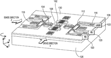
- FIG. 1 is a 3D sketch of one embodiment of the AOG.
- FIG. 2 schematically shows phase sensing techniques for the AOG where the secondary acoustic induced due to rotation is sensed as strain variation in the photonic waveguides:
- FIG. 2( a ) shows the strained waveguides as part of a PP-MZI and
- FIG. 2( b ) shows the strained waveguides as part of an RT resonator.
- FIG. 3 shows graphs of the RT transfer function and its derivative as function of phase, wherein maximum phase sensitivity is obtained at one quarter of the full width half maximum.
- FIG. 5 schematically shows the layout of the MZI AOG with zoomed-in SEMs of the various components forming it.
- FIG. 6 schematically shows the layout of the RT AOG with zoomed-in SEMs of the various components forming it.
- FIG. 7( a ) shows the grating coupler design dimensions in one embodiment of the invention.
- FIG. 7( b ) shows the 3-dB MMI coupler design dimensions in one embodiment of the invention.
- FIG. 7( c ) shows the butterfly MMI coupler design dimensions in one embodiment of the invention.
- FIG. 8 shows the steps in the fabrication process flow for manufacturing the AOG.
- FIG. 9 is a graph of frequency response for the drive and sense cavities showing a mismatch of 40 kHz which is within the resonator bandwidth (100 kHz).
- FIG. 10( a ) shows a graph of measured insertion loss for the two output ports of the MZI as function of the wavelength.
- FIG. 10( b ) shows a graph of measured insertion loss for the RT as function of wavelength together with fitting. a, r and F were extracted from the fitting.
- FIG. 11 graphically shows the RT transfer function and its derivative as a function of phase for the actual losses and coupling condition.
- FIG. 12 schematically shows the AOG measurement setup.
- the optical setup with the positioners and manipulators are mounted on top of the rate table.
- FIG. 13( a ) is a graph showing the measured output voltage as a function of rotation rate together with fitting to extract the scale factor for each AOG.
- FIG. 13( b ) is a graph showing the theoretical comparison between the two photonic sensing techniques. The value of the expected gain factor for the experimentally demonstrated value of r is indicated on the plot.
- FIG. 14 is a graph showing the measured Allan deviation for the zero-rate output of the AOG compared with the experimental results for the same device tested as a SAWG (electro-acoustic read-out instead of acousto-optic).
- FIG. 1 depicts a schematic view of the AOG and offers an overview of its principle of operation.
- Two orthogonal SAW resonators 102 , 104 are provided with metallic pillars 106 placed at the center acting as the moving mass, M p , of the gyroscope.
- a SAW standing wave pattern is established along the drive (X) direction.
- the pillars 106 are placed inside the cavity at the anti-nodes of the SAW standing wave pattern, that is, at the location of the maximum x-directed velocity.
- the pillars 106 are driven longitudinally with vibration velocity, v p .
- the pillars are arranged in a checkerboard configuration such that their constructive interference establishes a secondary SAW in the sense (Z) direction.
- the secondary wave is detected through the elasto-optic effect in the photonic waveguides etched in the Lithium Niobate (LN) thin film, that is, by monitoring the refractive index change, ⁇ n, due to the strain induced by the secondary wave.
- p eff is the effective acousto-optic coefficient in the specific propagation direction of the SAW.
- the device can be operated as a SAWG with acousto-electrical sensing, wherein the output is sensed through the sense SAW resonator.
- FIG. 1 shows one embodiment of the invention wherein the photonic sensing technique using a push-pull MZI (PP-MZI) 112, which converts the phase modulation to intensity modulation at the photodetector output by mixing the optical beams from the two MZI arms.
- P-MZI push-pull MZI
- FIG. 1 shows one embodiment of the invention wherein the photonic sensing technique using a push-pull MZI (PP-MZI) 112, which converts the phase modulation to intensity modulation at the photodetector output by mixing the optical beams from the two MZI arms.
- P-MZI push-pull MZI
- other phase sensing techniques like AOG RT can also be used, as discussed below.
- T optical signal intensity
- G ⁇ T/ ⁇ AOG
- ⁇ AOG ⁇ AOG / ⁇ z
- the induced phase shift due to rotation, ⁇ AOG can be expressed in terms of the refractive index change, ⁇ n, and the waveguide length, L, as:
- ⁇ AOG ⁇ ⁇ ⁇ n ⁇ 2 ⁇ ⁇ ⁇ ⁇ L
- the vibration velocity in Eq. (1) can be expressed in terms of the drive parameters: the electrical power, P m , the drive resonator quality factor, Q D , the resonator equivalent mass, M r and the SAW resonance frequency, f m , as:
- M 2 (n 6 (p eff ) 2 )/( ⁇ v R 3 ) is the AO figure of merit of the material.
- FIG. 1 shows the two-phase sensing techniques considered for comparison in this study.
- FIG. 1( a ) represents a PP-MZI where E in represents the input electric field while E o1 and E o2 represent the output fields from the MMI coupler.
- T PP-MZI sin 2 ⁇ AOG .
- the factor of two in the argument of the sin function is due to the push-pull operation enabled by separating the centers of the MZI arms by a distance equal to 3 ⁇ /2. This separation implies opposite phase modulation in the two arms such that when one waveguide is under compression, the other one is under tension.
- the AOG RT phase sensing technique is shown in FIG. 1( b ) where an RT is coupled to a bus waveguide.
- the separation between the two straight arms in the RT is set to an even multiple of ⁇ /2, such that both waveguides will be either under compression or under tension at the same time.
- the transfer function for the RT can be expressed in terms of the round trip intrinsic loss inside the RT, a 2 , the coupling coefficient, r 2 , and the round trip total phase shift, ⁇ , as:
- T RT a 2 + r 2 - 2 ⁇ ar ⁇ ⁇ cos ⁇ ( ⁇ ) 1 + a 2 ⁇ r 2 - 2 ⁇ ar ⁇ ⁇ cos ⁇ ( ⁇ )
- FIG. 2 plots T RT and its derivative as function of ⁇ AOG .
- the finesse, F can be derived also in terms of a and r as
- the maximum AOG sensitivity gain can be derived as:
- the second value of a 0.99, corresponds to ultra-low losses (2.5 dB/m) that were recently reported for etched waveguide on the same LNOI substrate.
- the finesse of the cavity is varying along that curve as r varies and the dashed lines point out the F value at the points of maximum slope.
- the numerical analysis confirms our analytical conclusion that the gain in the SF is bounded by 2F/5. It also shows that the RT has to be under-coupled for maximum phase sensitivity.
- FIG. 4 and FIG. 5 show the layout views for the MZI-AOG and the RT-AOG respectively with zoomed-in SEMs of the various constitutive components.
- IDTs Interdigitated Transducers
- SAW reflectors SAW reflectors
- photonic waveguides are placed symmetrically with respect to a central pillar-filled cavity such as to ensure frequency matching between orthogonal SAW resonators.
- the IDTs in the sense direction are not excited electrically so that they have minimum effect on the secondary SAW standing wave pattern.
- the reason for having IDTs in the sense direction is to make sure that design is fully symmetric, and the frequencies of the drive and sense resonators are able to be matched.
- the light is coupled in and out using grating couplers 116 .
- the photonic readout shown in FIG. 4 is based on a (PP-MZI) where a Y junction is used for splitting the optical input into the two arms of the MZI and a 2 ⁇ 2 multimode interference (MMI) 3-dB coupler is used as a beam combiner.
- the differential output is detected using a balanced photodetector 120 .
- An RT is used in the photonic read-out where a butterfly MMI coupler is used to couple the light to the RT.
- the SAW resonator Q in the drive and sense directions can be fully harnessed when the frequencies of the orthogonal resonators are matched.
- Previous SAW gyroscope designs targeted SAW propagation direction and LN wafer cuts that provide the highest electromechanical coupling coefficient by driving the SAW in the Z direction for a Y cut LN wafer.
- the material properties in the two orthogonal in-plane directions (X and Z) are not the same due the trigonal crystalline structure of LN.
- Such a configuration makes frequency matching difficult.
- the two SAW resonators are rotated by ⁇ 45° with respect to the Z-direction to preserve symmetry, hence inherently matching the drive and sense frequencies.
- the SAW reflector has 700 fingers to ensure proper confinement of the SAW inside the cavity.
- Frequency matching between the drive direction (X) and the sense direction (Z) can also be attained by separately tuning the center frequencies of each acoustic cavity by modifying the electrical boundary conditions for the acoustic gratings (reflectors) 110 .
- By varying the electrical load attached to the reflectors between open circuit and short circuit conditions a continuous range of frequencies within a few 1,000s parts per million of the resonator center frequencies can be attained.
- grating couplers were used to couple light in and out of the photonic components.
- the grating coupler dimensions shown in FIG. 7( a ) were optimized for maximum coupling efficiency for the TE polarized light.
- the length of the waveguides of the MZI arms and the RT straight arm are chosen to be equal to the cavity length.
- the waveguides are placed at the positions of maximum strain in the SAW cavity.
- the separation of the MZI is set to 3 ⁇ /2 for push-pull operation while the RT straight arms' separation is set to 7 ⁇ to double the phase sensitivity.
- Electrodes can be placed next to the waveguides so as to apply an electric field across it and induce an index of refraction change through the electro-optic effect and tune the wavelength of operation of either the MZI or the RT.
- the fabrication process flow is depicted in FIG. 7 starting with a Y-cut LNOI 4′′ wafer.
- the LN thin film 130 (3′′ diameter and 500 nm in thickness) is bonded to silicon dioxide (SiO 2 , 1 ⁇ m thick) 128 on a LN substrate 126 .
- the thin film was formed by means of ion-implantation, slicing and polishing (A) by an external vendor.
- the first fabrication step consists in the lift-off of evaporated Al thin film, as shown in (B), which is set to be 100 nm thick and is used to define the IDT and reflector electrodes. After this step, a 140 nm Au layer lift-off is performed (C) for patterning of the pillars.
- Au may also be used for coating the Al pads to facilitate wire bonding for testing purposes.
- the next step is the deposition of SiO 2 (1 ⁇ m thick) (D), which is used as a mask layer during the LN etch. Chromium (Cr) (50 nm thick) is then deposited (E) and used as a mask for etching SiO 2 . This Cr layer is patterned twice. The first pattern is done with optical lithography to define the waveguides (WGs) (F). The second Cr patterning is performed at the die level using electron-beam lithography to define the grating couplers (G). Then SiO 2 is etched in a reactive ion etching (RIE) process using fluorine-based chemistry with the double-defined Cr mask (H).
- RIE reactive ion etching
- Chlorine-based chemistry is used in an inductively coupled plasma (ICP) RIE process to partially etch the LN with the SiO 2 mask (I).
- the Cr mask is also removed during the ICP etch step.
- the final step is dry etch (J) of SiO 2 to expose the metallic pads and completely remove it from the SAW resonator surface.
- the novel aspect of the fabrication process is that the transducers, the reflectors and the pillars are all fabricated in the same metallic layer.
- the metallic material of the layer can be one of a number of materials, such as tungsten (W), gold (Au), aluminum (Al), platinum (Pt), nickel (Ni), molybdenum (Mo), copper (Cu), iridium (Ir), ruthenium (Ru), palladium (Pd), and silver (Ag) or any alloy of the same.
- the SAW components may be composed of GaAs, AlN, Sc-doped AlN, PZT, GaN, ZnO. These materials may comprise the entire wafer or can be a thin film on silicon.
- the photonic components may be composed of LN, As2S3, GaAs, GaN, AlN, InGaAs, AlGaAs, InP, or any other material which can produce the acousto-optic effect.
- SAW Resonators The frequency responses of the drive and sense acoustic resonators are measured using a vector network analyzer (PNA N5230A) and RF probing. The measurement result showing the magnitude of the cross-coupling admittance, Y 21 , between the two ports of each resonator is reported in FIG. 8 .
- the quality factor and mismatch can be considered as the limiting aspect for the AOG bandwidth (50 kHz) which is well beyond what can be accomplished by MVGs.
- FIG. 9( a ) plots the MZI transfer function for the two outputs as a function of the wavelength. A balanced output is achieved near the design value of 1550 nm.
- the slight shift in the wavelength might be attributed to differences in the actual dimensions of the etched waveguides with respect to the design values.
- the envelope reflects the transfer function of the grating couplers.
- the RT transfer function with respect to the wavelength is plotted in FIG. 9( b ) together with the fitting (to Eq. 10) to extract the round trip loss, a, and the coupling coefficient, r, as well as the Finesse, F.
- the fitting of the RT transfer function due mostly to the assumption of having a single mode waveguide (note that the waveguides are 2 ⁇ m wide due to fabrication constraints and well above the width required for single-mode operation), it is possible to confidently extract the values of a and r for the fabricated RT.
- the fiber to chip coupling loss for the MZI was about ⁇ 35 dB while that for the RT was about ⁇ 36 dB.
- the minimum insertion loss for the RT was found at an optical wavelength near 1528 nm, which is different from the design wavelength of the butterfly MMI coupler.
- the high coupling loss is attributed mostly to the accuracy of the fiber alignment to the photonic chip and to the fabrication tolerance of the gratings couplers dimensions.
- Prior work on LNOI gratings couplers has demonstrated insertion loss of about 12 dB per coupler.
- an Erbium Doped Fiber Amplifier (EDFA) is used as described in the next section.
- EDFA Erbium Doped Fiber Amplifier
- FIG. 11 plots the RT transfer function and its derivative for the coupling condition that was achieved experimentally and shows the bias point for maximum sensitivity. Although the attained losses match the one simulated in FIG. 4 , it is clear that because of the achieved value of r, the RT configuration is not expected to yield a net enhancement in the sensitivity of the AOG.
- the plot also shows the bias point at the phase offset of one quarter of the full width half maximum. In terms of wavelength, the bias point can be derived as
- ⁇ max ⁇ 2 2 ⁇ ⁇ ⁇ ⁇ nL ⁇ ⁇ max .
- the AOG measurement setup is shown in FIG. 11 where each of the AOG samples is mounted on a rate table together with the optical positioners and connected to the measurement instruments.
- the gyroscope die is packaged in a Pin Grid Array (PGA) ceramic package.
- An Ultra-High Frequency Lock-In (UHFLI) amplifier from Zurich Instruments is used to phase lock the SAW drive resonator using a built-in Phase Locked Loop (PLL).
- PLL Phase Locked Loop
- PID Proportional Integral Derivative
- An optical carrier generated by a benchtop tunable laser 122 is coupled into the optical grating 116 via a vertical groove array (VGA).
- VGA vertical groove array
- a polarization controller is used after the laser 122 to make sure that the TE polarization is excited, for which the gratings couplers were optimized.
- the same VGA is also used to couple out the modulated gyroscope signal through another set of fibers in the array.
- the EDFA is placed after the output coupler to compensate for the coupling loss.
- the optical alignment is optimized by adjusting a six degree of freedom manipulator while looking for maximum transmission as the if wavelength is being swept.
- the photonic output is fed to the lock-in amplifier where the Coriolis component is separated from the quadrature component. Due to the RF cables and fibers, full 360° rotations for the rate table are not possible.
- the input rotation is applied as a sinusoidal oscillation to the rate table. To make sure the optical alignment between the fibers and the gratings couplers does not affect the measurement results, the input rotation frequency is limited to 2 Hz and the amplitude to 8 degrees.
- the SF can be extracted for each AOG as the slope of the straight line in FIG. (a).
- Due to variations in the coupling efficiency, the values of the SF vary from measurement to measurement within ⁇ 58% of the average value of 48 nV/(°/sec) and 9 nV/(°/sec) respectively for the PP-MZI and the RT detection methods.
- the expected theoretical values for the SFs can be obtained directly from Eq.
- the zero-rate output (ZRO) of the MZI-AOG was recorded for 4 hours and its Allan deviation is plotted in FIG. 14 from where ARW of 60°/ ⁇ square root over (hr) ⁇ and bias instability less than 1°/sec can be extracted.
- FIG. 14 also compares the noise performance of the AOG with the same gyroscope but operated as a SAWG with acousto-electrical sensing (i.e. the output is sensed through the sense SAW resonator). The results highlight the better stability of the AOG due to the decoupling between the acoustic drive signal and the optical sensing signal.
- this first prototype shows the feasibility of the proposed idea and lays the foundations for further engineering of a high-performance component.
- a novel rotation sensing technique based on the acousto-optic effect has been disclosed herein.
- Two different photonic phase sensing techniques are considered and compared both theoretically and experimentally.
- the manufacturability of this novel device is made possible by the development of a fabrication process that integrates acoustic and photonic components on the same LNOI platform.
- the experimental results demonstrate the feasibility of the proposed AOG and, most importantly, verify the theoretical description of its principle of operation.
- the invention could yield more than 20 ⁇ improvements by reducing the losses on the photonic components and properly designing the MMI coupler.
- Such improvements yield enhancement of about 20 ⁇ in the SF and the ARW.
- additional 20 ⁇ improvement is possible by increasing the SAW resonators Q and operating at a larger acoustic wavelength.
- a new class of highly sensitive strain-based acousto-optic gyroscopes can be developed.
Landscapes
- Physics & Mathematics (AREA)
- Acoustics & Sound (AREA)
- Engineering & Computer Science (AREA)
- General Physics & Mathematics (AREA)
- Radar, Positioning & Navigation (AREA)
- Remote Sensing (AREA)
- Multimedia (AREA)
- Gyroscopes (AREA)
Abstract
Description
F c=−2M pΩz ×v p (1)
Δn=½n 3 p eff S (3)
Rotation-Induced Phase Changes
G PP-MZI=2
is the round trip phase shift, and LT is the total racetrack length. Thus:
The plot in
has a maximum at a specific phase offset that equals to one quarter of the full width half maximum (Δφ
Accordingly, the maximum AOG sensitivity gain can be derived as:
in Eq. (11) to get:
so as to find a very simple expression of the RT gain factor:
AOG SF Measurement
Claims (23)
Priority Applications (1)
| Application Number | Priority Date | Filing Date | Title |
|---|---|---|---|
| US16/151,010 US11112245B2 (en) | 2017-10-03 | 2018-10-03 | Acousto-optic gyroscopes |
Applications Claiming Priority (2)
| Application Number | Priority Date | Filing Date | Title |
|---|---|---|---|
| US201762606676P | 2017-10-03 | 2017-10-03 | |
| US16/151,010 US11112245B2 (en) | 2017-10-03 | 2018-10-03 | Acousto-optic gyroscopes |
Publications (2)
| Publication Number | Publication Date |
|---|---|
| US20190120624A1 US20190120624A1 (en) | 2019-04-25 |
| US11112245B2 true US11112245B2 (en) | 2021-09-07 |
Family
ID=66170478
Family Applications (1)
| Application Number | Title | Priority Date | Filing Date |
|---|---|---|---|
| US16/151,010 Active 2039-08-25 US11112245B2 (en) | 2017-10-03 | 2018-10-03 | Acousto-optic gyroscopes |
Country Status (1)
| Country | Link |
|---|---|
| US (1) | US11112245B2 (en) |
Families Citing this family (6)
| Publication number | Priority date | Publication date | Assignee | Title |
|---|---|---|---|---|
| CN110227640B (en) * | 2019-06-18 | 2021-01-26 | 京东方科技集团股份有限公司 | Piezoelectric sensor assembly, method of making the same, and display panel |
| US11898844B2 (en) | 2019-10-03 | 2024-02-13 | Cornell University | Shear wave methods, systems, and gyroscope |
| US11531172B2 (en) * | 2020-05-13 | 2022-12-20 | Globalfoundries U.S. Inc. | Wafer-level testing of lasers attached to photonics chips |
| CN112066967B (en) * | 2020-07-07 | 2023-02-14 | 西北工业大学 | Chip-level resonant acousto-optic coupling solid-state fluctuation gyroscope |
| CN113086940B (en) * | 2021-03-25 | 2024-01-26 | 武汉敏声新技术有限公司 | Nano-optomechanical gyroscope and preparation method thereof |
| CN113340289B (en) * | 2021-06-04 | 2023-01-24 | 西北工业大学 | A chip-level disc acousto-optic standing wave gyroscope |
Citations (7)
| Publication number | Priority date | Publication date | Assignee | Title |
|---|---|---|---|---|
| US4965479A (en) * | 1987-01-12 | 1990-10-23 | Hewlett-Packard Company | Surface transverse wave resonator |
| US5144262A (en) * | 1989-10-10 | 1992-09-01 | Electronic Decisions Incorporated | Acoustic charge transport selectable delay line and delay line oscillator formed therewith |
| US6031315A (en) * | 1997-07-16 | 2000-02-29 | Sawtek Inc. | Optimal cut for saw devices on quartz |
| US20080028855A1 (en) * | 2006-07-25 | 2008-02-07 | Denso Corporation | Angular rate sensor |
| US20090133495A1 (en) * | 2007-11-28 | 2009-05-28 | Denso Corporation | Yaw rate sensor using surface acoustic wave |
| US20200173780A1 (en) * | 2017-08-24 | 2020-06-04 | Agency For Science, Technology And Research | Gyroscope, methods of forming and operating the same |
| US20200408800A1 (en) * | 2016-03-02 | 2020-12-31 | Cornell University | Surface Acoustic Wave (SAW)-based Inertial Sensor, Methods, and Applications |
-
2018
- 2018-10-03 US US16/151,010 patent/US11112245B2/en active Active
Patent Citations (7)
| Publication number | Priority date | Publication date | Assignee | Title |
|---|---|---|---|---|
| US4965479A (en) * | 1987-01-12 | 1990-10-23 | Hewlett-Packard Company | Surface transverse wave resonator |
| US5144262A (en) * | 1989-10-10 | 1992-09-01 | Electronic Decisions Incorporated | Acoustic charge transport selectable delay line and delay line oscillator formed therewith |
| US6031315A (en) * | 1997-07-16 | 2000-02-29 | Sawtek Inc. | Optimal cut for saw devices on quartz |
| US20080028855A1 (en) * | 2006-07-25 | 2008-02-07 | Denso Corporation | Angular rate sensor |
| US20090133495A1 (en) * | 2007-11-28 | 2009-05-28 | Denso Corporation | Yaw rate sensor using surface acoustic wave |
| US20200408800A1 (en) * | 2016-03-02 | 2020-12-31 | Cornell University | Surface Acoustic Wave (SAW)-based Inertial Sensor, Methods, and Applications |
| US20200173780A1 (en) * | 2017-08-24 | 2020-06-04 | Agency For Science, Technology And Research | Gyroscope, methods of forming and operating the same |
Non-Patent Citations (1)
| Title |
|---|
| Nakamura et al.,"Trapped-Energy Vibratory Gyroscopes Using Rotated Y-cut LiNbO3", Jpn. J. Appl. Phys. vol. 37 (Year: 1998). * |
Also Published As
| Publication number | Publication date |
|---|---|
| US20190120624A1 (en) | 2019-04-25 |
Similar Documents
| Publication | Publication Date | Title |
|---|---|---|
| US11112245B2 (en) | Acousto-optic gyroscopes | |
| Mahmoud et al. | Novel on chip rotation detection based on the acousto-optic effect in surface acoustic wave gyroscopes | |
| US6668111B2 (en) | Optical microcavity resonator sensor | |
| US9243998B2 (en) | Resonant photo acoustic system | |
| US9389079B2 (en) | Optomechanical disk vibratory gyroscopes | |
| EP0104943A2 (en) | Stabilized fiber optic sensor | |
| US20220307836A1 (en) | A chip-level resonant acousto-optic coupled solid state wave gyroscope | |
| US10794813B2 (en) | Micro or nanomechanical particle detection device | |
| US8203718B2 (en) | Photonic crystal based sensor or modulator | |
| WO2002001146A1 (en) | Optical microcavity resonator sensor | |
| JPS62254020A (en) | Spectrum analysis and optical fiber device and method for filter | |
| CN109781087A (en) | A SAW Gyroscope Based on Standing Wave Mode | |
| US20200173780A1 (en) | Gyroscope, methods of forming and operating the same | |
| JP2025520362A (en) | A compact interferometric integrated photonic gyroscope | |
| US20130008229A1 (en) | Resonant photo acoustic system | |
| Mahmoud et al. | Investigating the impact of resonant cavity design on surface acoustic wave gyroscope | |
| Tian et al. | A novel progressive wave gyroscope based on acousto-optic effects | |
| Mahmoud et al. | Acousto-optic gyroscope | |
| US10788687B2 (en) | System for transduction of displacement to optical phase shift | |
| Hoffmann et al. | Micromechanical cantilever resonators with integrated optical interrogation | |
| Kurosu et al. | Buckling-induced quadratic nonlinearity in silicon phonon waveguide structures | |
| Mahmoud et al. | Acousto-optic gyroscope with improved sensitivity and 100 second stability in a small form factor | |
| Lee et al. | Enhancing the sensitivity of three-axis detectable surface acoustic wave gyroscope by using a floating thin piezoelectric membrane | |
| Bhat et al. | Optomechanical sensing of wine-glass modes of a BAW resonator | |
| Leoncino | Optomechanical transduction applied to M/NEMS devices |
Legal Events
| Date | Code | Title | Description |
|---|---|---|---|
| FEPP | Fee payment procedure |
Free format text: ENTITY STATUS SET TO UNDISCOUNTED (ORIGINAL EVENT CODE: BIG.); ENTITY STATUS OF PATENT OWNER: SMALL ENTITY |
|
| FEPP | Fee payment procedure |
Free format text: ENTITY STATUS SET TO SMALL (ORIGINAL EVENT CODE: SMAL); ENTITY STATUS OF PATENT OWNER: SMALL ENTITY |
|
| STPP | Information on status: patent application and granting procedure in general |
Free format text: DOCKETED NEW CASE - READY FOR EXAMINATION |
|
| STPP | Information on status: patent application and granting procedure in general |
Free format text: RESPONSE TO NON-FINAL OFFICE ACTION ENTERED AND FORWARDED TO EXAMINER |
|
| STPP | Information on status: patent application and granting procedure in general |
Free format text: NOTICE OF ALLOWANCE MAILED -- APPLICATION RECEIVED IN OFFICE OF PUBLICATIONS |
|
| AS | Assignment |
Owner name: CARNEGIE MELLON UNIVERSITY, PENNSYLVANIA Free format text: ASSIGNMENT OF ASSIGNORS INTEREST;ASSIGNORS:PIAZZA, GIANLUCA;MAHMOUD, MOHAMED;MAHMOUD, ASHRAF;AND OTHERS;SIGNING DATES FROM 20201021 TO 20210723;REEL/FRAME:057005/0677 |
|
| STPP | Information on status: patent application and granting procedure in general |
Free format text: PUBLICATIONS -- ISSUE FEE PAYMENT VERIFIED |
|
| STCF | Information on status: patent grant |
Free format text: PATENTED CASE |
|
| MAFP | Maintenance fee payment |
Free format text: PAYMENT OF MAINTENANCE FEE, 4TH YR, SMALL ENTITY (ORIGINAL EVENT CODE: M2551); ENTITY STATUS OF PATENT OWNER: SMALL ENTITY Year of fee payment: 4 |