US11111802B2 - Seal for a gas turbine engine - Google Patents
Seal for a gas turbine engine Download PDFInfo
- Publication number
- US11111802B2 US11111802B2 US16/400,618 US201916400618A US11111802B2 US 11111802 B2 US11111802 B2 US 11111802B2 US 201916400618 A US201916400618 A US 201916400618A US 11111802 B2 US11111802 B2 US 11111802B2
- Authority
- US
- United States
- Prior art keywords
- pair
- axially
- aft surface
- circumferential surfaces
- platform
- Prior art date
- Legal status (The legal status is an assumption and is not a legal conclusion. Google has not performed a legal analysis and makes no representation as to the accuracy of the status listed.)
- Active, expires
Links
Images


Classifications
-
- F—MECHANICAL ENGINEERING; LIGHTING; HEATING; WEAPONS; BLASTING
- F01—MACHINES OR ENGINES IN GENERAL; ENGINE PLANTS IN GENERAL; STEAM ENGINES
- F01D—NON-POSITIVE DISPLACEMENT MACHINES OR ENGINES, e.g. STEAM TURBINES
- F01D11/00—Preventing or minimising internal leakage of working-fluid, e.g. between stages
- F01D11/001—Preventing or minimising internal leakage of working-fluid, e.g. between stages for sealing space between stator blade and rotor
-
- F—MECHANICAL ENGINEERING; LIGHTING; HEATING; WEAPONS; BLASTING
- F01—MACHINES OR ENGINES IN GENERAL; ENGINE PLANTS IN GENERAL; STEAM ENGINES
- F01D—NON-POSITIVE DISPLACEMENT MACHINES OR ENGINES, e.g. STEAM TURBINES
- F01D11/00—Preventing or minimising internal leakage of working-fluid, e.g. between stages
- F01D11/005—Sealing means between non relatively rotating elements
-
- F—MECHANICAL ENGINEERING; LIGHTING; HEATING; WEAPONS; BLASTING
- F01—MACHINES OR ENGINES IN GENERAL; ENGINE PLANTS IN GENERAL; STEAM ENGINES
- F01D—NON-POSITIVE DISPLACEMENT MACHINES OR ENGINES, e.g. STEAM TURBINES
- F01D11/00—Preventing or minimising internal leakage of working-fluid, e.g. between stages
- F01D11/003—Preventing or minimising internal leakage of working-fluid, e.g. between stages by packing rings; Mechanical seals
-
- F—MECHANICAL ENGINEERING; LIGHTING; HEATING; WEAPONS; BLASTING
- F01—MACHINES OR ENGINES IN GENERAL; ENGINE PLANTS IN GENERAL; STEAM ENGINES
- F01D—NON-POSITIVE DISPLACEMENT MACHINES OR ENGINES, e.g. STEAM TURBINES
- F01D11/00—Preventing or minimising internal leakage of working-fluid, e.g. between stages
- F01D11/005—Sealing means between non relatively rotating elements
- F01D11/006—Sealing the gap between rotor blades or blades and rotor
-
- F—MECHANICAL ENGINEERING; LIGHTING; HEATING; WEAPONS; BLASTING
- F01—MACHINES OR ENGINES IN GENERAL; ENGINE PLANTS IN GENERAL; STEAM ENGINES
- F01D—NON-POSITIVE DISPLACEMENT MACHINES OR ENGINES, e.g. STEAM TURBINES
- F01D25/00—Component parts, details, or accessories, not provided for in, or of interest apart from, other groups
- F01D25/24—Casings; Casing parts, e.g. diaphragms, casing fastenings
- F01D25/246—Fastening of diaphragms or stator-rings
-
- F—MECHANICAL ENGINEERING; LIGHTING; HEATING; WEAPONS; BLASTING
- F01—MACHINES OR ENGINES IN GENERAL; ENGINE PLANTS IN GENERAL; STEAM ENGINES
- F01D—NON-POSITIVE DISPLACEMENT MACHINES OR ENGINES, e.g. STEAM TURBINES
- F01D9/00—Stators
- F01D9/02—Nozzles; Nozzle boxes; Stator blades; Guide conduits, e.g. individual nozzles
- F01D9/04—Nozzles; Nozzle boxes; Stator blades; Guide conduits, e.g. individual nozzles forming ring or sector
- F01D9/042—Nozzles; Nozzle boxes; Stator blades; Guide conduits, e.g. individual nozzles forming ring or sector fixing blades to stators
-
- B—PERFORMING OPERATIONS; TRANSPORTING
- B24—GRINDING; POLISHING
- B24B—MACHINES, DEVICES, OR PROCESSES FOR GRINDING OR POLISHING; DRESSING OR CONDITIONING OF ABRADING SURFACES; FEEDING OF GRINDING, POLISHING, OR LAPPING AGENTS
- B24B19/00—Single-purpose machines or devices for particular grinding operations not covered by any other main group
- B24B19/02—Single-purpose machines or devices for particular grinding operations not covered by any other main group for grinding grooves, e.g. on shafts, in casings, in tubes, homokinetic joint elements
-
- F—MECHANICAL ENGINEERING; LIGHTING; HEATING; WEAPONS; BLASTING
- F05—INDEXING SCHEMES RELATING TO ENGINES OR PUMPS IN VARIOUS SUBCLASSES OF CLASSES F01-F04
- F05D—INDEXING SCHEME FOR ASPECTS RELATING TO NON-POSITIVE-DISPLACEMENT MACHINES OR ENGINES, GAS-TURBINES OR JET-PROPULSION PLANTS
- F05D2230/00—Manufacture
- F05D2230/10—Manufacture by removing material
-
- F—MECHANICAL ENGINEERING; LIGHTING; HEATING; WEAPONS; BLASTING
- F05—INDEXING SCHEMES RELATING TO ENGINES OR PUMPS IN VARIOUS SUBCLASSES OF CLASSES F01-F04
- F05D—INDEXING SCHEME FOR ASPECTS RELATING TO NON-POSITIVE-DISPLACEMENT MACHINES OR ENGINES, GAS-TURBINES OR JET-PROPULSION PLANTS
- F05D2230/00—Manufacture
- F05D2230/60—Assembly methods
-
- F—MECHANICAL ENGINEERING; LIGHTING; HEATING; WEAPONS; BLASTING
- F05—INDEXING SCHEMES RELATING TO ENGINES OR PUMPS IN VARIOUS SUBCLASSES OF CLASSES F01-F04
- F05D—INDEXING SCHEME FOR ASPECTS RELATING TO NON-POSITIVE-DISPLACEMENT MACHINES OR ENGINES, GAS-TURBINES OR JET-PROPULSION PLANTS
- F05D2240/00—Components
- F05D2240/55—Seals
- F05D2240/57—Leaf seals
-
- F—MECHANICAL ENGINEERING; LIGHTING; HEATING; WEAPONS; BLASTING
- F05—INDEXING SCHEMES RELATING TO ENGINES OR PUMPS IN VARIOUS SUBCLASSES OF CLASSES F01-F04
- F05D—INDEXING SCHEME FOR ASPECTS RELATING TO NON-POSITIVE-DISPLACEMENT MACHINES OR ENGINES, GAS-TURBINES OR JET-PROPULSION PLANTS
- F05D2240/00—Components
- F05D2240/80—Platforms for stationary or moving blades
Definitions
- a gas turbine engine typically includes a fan section, a compressor section, a combustor section, and a turbine section. Air entering the compressor section is compressed and delivered into the combustion section where it is mixed with fuel and ignited to generate a high-speed exhaust gas flow. The high-speed exhaust gas flow expands through the turbine section to drive the compressor and the fan section.
- Feather seals are commonly utilized in aerospace and other industries to provide a seal between two adjacent components.
- gas turbine engine vanes are arranged in a circumferential configuration to form an annular vane ring structure about a center axis of the engine.
- each stator segment includes an airfoil and a platform section. When assembled, the platforms abut and define a radially inner and radially outer boundary to receive hot gas core airflow.
- each platform typically includes a channel which receives a feather seal assembly that seals the hot gas core airflow from a surrounding medium such as a cooling airflow.
- Feather seals are often typical of the first stage of a high pressure turbine in a twin spool engine.
- Feather seals may also be an assembly of seals joined together through a welded tab and slot geometry which may be relatively expensive and complicated to manufacture.
- a component for a gas turbine engine includes a first platform that has a first pair of circumferential surfaces and a first axially aft surface.
- a first axially extending seal slot is located in each of the first pair of circumferential surfaces and the first axially aft surface.
- a first cover plate is attached to the first axially aft surface and encloses at least a portion of the first axially extending seal slots.
- the first axially aft surface intersects the pair of circumferential surfaces.
- the first axially extending seal slots are formed with a grinding process.
- the first cover plate is welded to the first axially aft surface.
- first axially extending seal slots extend through a leading edge of the first platform.
- a portion of the first axially aft surface defines a trailing edge rail.
- the axially aft surface intersects the pair of circumferential surfaces and the component includes one of a blade outer air seal or an airfoil.
- the component is an airfoil and includes an airfoil that has a first end adjacent the first platform.
- a second end is adjacent a second platform and has a second pair of circumferential surfaces and a second axially aft surface.
- a second axially extending seal slot is located in each of the second pair of circumferential surfaces and the second axially aft surface.
- a second cover plate is attached to the second axially aft surface and encloses at least a portion of the second axially extending seal slots.
- a gas turbine engine in another exemplary embodiment, includes a compressor section upstream of a combustor section.
- a turbine section is downstream of the combustor section.
- At least one of the compressor section or the turbine section includes a component that has a first platform that has a first pair of circumferential surfaces and a first axially aft surface.
- a first axially extending seal slot is located in each of the first pair of circumferential surfaces and the first axially aft surface.
- a first cover plate is attached to the first axially aft surface and encloses at least a portion of the first axially extending seal slots.
- the first axially aft surface intersects the pair of circumferential surfaces.
- the first axially extending seal slots are formed with a grinding process.
- the first cover plate is welded to the axially aft surface.
- the first axially extending seal slot extends through a leading edge of the first platform.
- the component is an airfoil and includes an airfoil that has a first end adjacent the first platform.
- a second end is adjacent a second platform that has a second pair of circumferential surfaces and a second axially aft surface.
- a second axially extending seal slot is located in each of the second pair of circumferential surfaces and the second axially aft surface.
- a second cover plate is attached to the second axially aft surface and encloses at least a portion of the second axially extending seal slots.
- a method of forming a seal slot in a component includes the step of forming a first axially extending seal slot through each of a pair of first circumferential surfaces and a first axially aft surface on a first platform. A portion of the first axially extending seal slot is enclosed with a cover plate attached to the first axially aft surface.
- the first axially extending seal slot is formed through a grinding process.
- the method includes the step of forming a second axially extending seal slot through each of a pair of second circumferential surfaces and a second axially aft surface of a second platform opposite the first platform. At least a portion of the pair of second axially extending seal slot is enclosed with a second cover plate attached to the second axially aft surface.
- the second axially extending seal slot is formed through a grinding process.
- the second cover plate is welded to the first axially aft surface.
- FIG. 1 is a schematic view of a gas turbine engine according to a first non-limiting example.
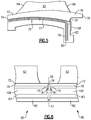
- FIG. 2 illustrates a perspective view of an example vane.
- FIG. 3 illustrates an enlarged view of a radially outer platform of the van of FIG. 2 with a cover plate.
- FIG. 4 illustrates a pair of adjacent outer platforms with a feather seal.
- FIG. 5 is an enlarged view of an inner platform with a cover plate.
- FIG. 6 illustrates a pair of adjacent inner platforms with a feather seal.
- FIG. 7 illustrates an example blade outer air seal.
- FIG. 1 schematically illustrates a gas turbine engine 20 .
- the gas turbine engine 20 is disclosed herein as a two-spool turbofan that generally incorporates a fan section 22 , a compressor section 24 , a combustor section 26 and a turbine section 28 .
- the fan section 22 drives air along a bypass flow path B in a bypass duct defined within a nacelle 15 , and also drives air along a core flow path C for compression and communication into the combustor section 26 then expansion through the turbine section 28 .
- the exemplary engine 20 generally includes a low speed spool 30 and a high speed spool 32 mounted for rotation about an engine central longitudinal axis A relative to an engine static structure 36 via several bearing systems 38 . It should be understood that various bearing systems 38 at various locations may alternatively or additionally be provided, and the location of bearing systems 38 may be varied as appropriate to the application.
- the low speed spool 30 generally includes an inner shaft 40 that interconnects, a first (or low) pressure compressor 44 and a first (or low) pressure turbine 46 .
- the inner shaft 40 is connected to the fan 42 through a speed change mechanism, which in exemplary gas turbine engine 20 is illustrated as a geared architecture 48 to drive a fan 42 at a lower speed than the low speed spool 30 .
- the high speed spool 32 includes an outer shaft 50 that interconnects a second (or high) pressure compressor 52 and a second (or high) pressure turbine 54 .
- a combustor 56 is arranged in exemplary gas turbine 20 between the high pressure compressor 52 and the high pressure turbine 54 .
- a mid-turbine frame 57 of the engine static structure 36 may be arranged generally between the high pressure turbine 54 and the low pressure turbine 46 .
- the mid-turbine frame 57 further supports bearing systems 38 in the turbine section 28 .
- the inner shaft 40 and the outer shaft 50 are concentric and rotate via bearing systems 38 about the engine central longitudinal axis A which is collinear with their longitudinal axes.
- the core airflow is compressed by the low pressure compressor 44 then the high pressure compressor 52 , mixed and burned with fuel in the combustor 56 , then expanded over the high pressure turbine 54 and low pressure turbine 46 .
- the mid-turbine frame 57 includes airfoils 59 which are in the core airflow path C.
- the turbines 46 , 54 rotationally drive the respective low speed spool 30 and high speed spool 32 in response to the expansion. It will be appreciated that each of the positions of the fan section 22 , compressor section 24 , combustor section 26 , turbine section 28 , and fan drive gear system 48 may be varied.
- gear system 48 may be located aft of the low pressure compressor, or aft of the combustor section 26 or even aft of turbine section 28 , and fan 42 may be positioned forward or aft of the location of gear system 48 .
- the engine 20 in one example is a high-bypass geared aircraft engine.
- the engine 20 bypass ratio is greater than about six (6), with an example embodiment being greater than about ten (10)
- the geared architecture 48 is an epicyclic gear train, such as a planetary gear system or other gear system, with a gear reduction ratio of greater than about 2.3
- the low pressure turbine 46 has a pressure ratio that is greater than about five.
- the engine 20 bypass ratio is greater than about ten (10:1)
- the fan diameter is significantly larger than that of the low pressure compressor 44
- the low pressure turbine 46 has a pressure ratio that is greater than about five 5:1.
- Low pressure turbine 46 pressure ratio is pressure measured prior to inlet of low pressure turbine 46 as related to the pressure at the outlet of the low pressure turbine 46 prior to an exhaust nozzle.
- the geared architecture 48 may be an epicycle gear train, such as a planetary gear system or other gear system, with a gear reduction ratio of greater than about 2.3:1 and less than about 5:1. It should be understood, however, that the above parameters are only exemplary of one embodiment of a geared architecture engine and that the present invention is applicable to other gas turbine engines including direct drive turbofans.
- the fan section 22 of the engine 20 is designed for a particular flight condition—typically cruise at about 0.8 Mach and about 35,000 feet (10,668 meters).
- ′TSFC Thrust Specific Fuel Consumption
- Low fan pressure ratio is the pressure ratio across the fan blade alone, without a Fan Exit Guide Vane (“FEGV”) system.
- the low fan pressure ratio as disclosed herein according to one non-limiting embodiment is less than about 1.45.
- Low corrected fan tip speed is the actual fan tip speed in ft/sec divided by an industry standard temperature correction of [(Tram ° R)/(518.7° R)] 0.5 .
- the “Low corrected fan tip speed” as disclosed herein according to one non-limiting embodiment is less than about 1150 ft/second (350.5 meters/second).
- FIG. 2 illustrates an example vane 60 .
- the vane 60 includes an airfoil 62 extending axially between a leading edge 64 and a trailing edge 66 .
- the leading edge 64 and the trailing edge 66 also separate a pressure side 68 from a suction side 70 on the airfoil 62 .
- the airfoil 62 extends radially outward from an inner platform 72 to an outer platform 86 .
- the inner platform 72 includes a leading edge 74 and a trailing edge 76 that extend between circumferential side surfaces 78 .
- An axially extending feather seal slot 75 extends through each of the circumferential side surfaces 78 .
- the inner platform 72 also includes an inner rail 82 extending inward from an axially aft portion of the inner platform 72 .
- the inner rail 82 also includes an inner rail feather seal slot 84 that extends in a radial direction.
- axial or axially and radial or radially is with respect to the engine axis A unless stated otherwise.
- the radially outer platform 86 includes a leading edge 88 and a trailing edge 90 that extend between opposite circumferential side surfaces 92 .
- the outer platform 86 also includes an axially extending feather seal slot 94 in each of the circumferential side surfaces 92 .
- the feather seal slot 94 is formed through a grinding process.
- the grinding process used to form the feather seal slot 94 produces a smoother surface finish which increases contact area with a feather seal 104 ( FIG. 4 ) to reduce air loss between adjacent vanes 60 .
- the grinding process creates a surface roughness of between 10 and 125 RA. Additionally, because the feather seal slot 94 is formed with a grinding process, the feather seal slot 94 is linear.
- the surface roughness resulting from the grinding process is an improvement over a traditional process that utilizes EDM to form the feather seal slot 94 .
- the surface roughness formed from EDM is approximately 250 RA.
- an end gap 95 is formed in an axially aft surface 100 of the outer platform 86 .
- the axially aft surface 100 extends circumferentially along the outer platform 86 and an outer rail 96 .
- the outer rail 96 also includes an outer rail feather seal slot 98 that extends in a radial direction.
- the outer rail feather seal slot 98 is formed from an EDM process.
- a surface roughness of the feather seal slot 94 has a different surface roughness than the outer rail feather seal slot 98 .
- each of the circumferential side surfaces 92 include the feather seal slot 94 that is formed with the grinding process.
- the leading edge 88 of the outer platform 86 also includes an opening corresponding to the feather seal slots 94 in each of the opposing circumferential side surfaces 92 .
- the end gaps 95 are at least partially enclosed by a cover plate 102 .
- the cover plate 102 extends a substantial width of the axially aft surface 100 and is attached to the axially aft surface 100 by a laser welding process.
- the cover plate 102 extends to adjacent the circumferential side surfaces 92 .
- the cover plate 102 is shown as being a single piece in the illustrated example, the cover plate 102 can be formed from multiple pieces that at least partially enclose a corresponding one of the end gaps 95 .
- the feather seal 104 is in engagement with adjacent vanes 60 .
- the cover plates 102 on each of the vanes 60 are adjacent to the circumferential side surfaces 92 of each of the vanes 60 . This decreases the amount of air loss traveling through the feather seal slot 94 through the axially aft surface 100 .
- a cover plate 102 instead of welding the end gap 95 shut, there is less of a chance that the vane 60 will be damaged while welding the end gaps 95 as opposed to welding the cover plate 102 onto the axially aft surface 100 . This results in a decreased number of vane 60 that do not meet manufacturing tolerances due to damage resulting from welding one of the end gaps 95 .
- the radially inner platform 72 includes the axially extending feather seal slot 75 in each circumferential side surface 78 .
- the feather seal slot 75 is formed through a grinding process.
- the grinding process used to form the feather seal slot 75 produces a smoother surface finish which increases contact area with a feather seal 77 ( FIG. 5 ) to reduce air loss between adjacent vanes 60 as described above with respect to the feather seal slot 94 .
- the leading edge 74 of the inner platform 72 also includes an opening corresponding to the feather seal slot 75 in each of the opposing circumferential side surfaces 92 .
- an end gap 81 is formed in an axially aft surface 83 of the inner platform 72 .
- the inner rail 82 also includes an inner rail feather seal slot 79 that extends in a radial direction.
- the inner rail feather seal slot 79 is formed from an EDM process. Therefore, a surface roughness of the feather seal slot 79 has a different surface roughness than the outer rail feather seal slot 75 similar to the outer rail feather seal slot 98 described above.
- the end gaps 81 are at least partially enclosed by a cover plate 106 .
- the cover plate 106 extends a substantial width of the axially aft surface 83 and is attached to the axially aft surface 83 by a laser welding process.
- the cover plate 106 extends to adjacent the circumferential side surfaces 78 .
- the cover plate 106 is shown as being a single piece in the illustrated example, the cover plate 106 can be formed from multiple pieces that at least partially enclose a corresponding one of the end gaps 81 .
- FIG. 7 schematically illustrates the disclosure directed to a blade outer air seal 120 .
- the blade outer air seal 120 includes a trailing edge surface 122 that extend between opposite circumferential side surfaces 124 .
- the blade outer air seal 120 also includes an axially extending feather seal slot 126 in each of the circumferential side surfaces 92 and a radially extending feather seal slot 127 for accepting a feather seal 132 .
- the feather seal slot 126 is formed through a grinding process similar to the axially extending feather seal slots described above.
- the feather seal slot 126 also forms an end gap 128 in the trailing edge surface 122 .
- a cover plate 130 is secured to the trailing edge surface 122 and at least partially encloses the end cap 128 .
Landscapes
- Engineering & Computer Science (AREA)
- Mechanical Engineering (AREA)
- General Engineering & Computer Science (AREA)
- Turbine Rotor Nozzle Sealing (AREA)
- Structures Of Non-Positive Displacement Pumps (AREA)
Abstract
Description
Claims (19)
Priority Applications (2)
| Application Number | Priority Date | Filing Date | Title |
|---|---|---|---|
| US16/400,618 US11111802B2 (en) | 2019-05-01 | 2019-05-01 | Seal for a gas turbine engine |
| EP20168955.1A EP3734018B1 (en) | 2019-05-01 | 2020-04-09 | Seal for a gas turbine engine component and corresponding method |
Applications Claiming Priority (1)
| Application Number | Priority Date | Filing Date | Title |
|---|---|---|---|
| US16/400,618 US11111802B2 (en) | 2019-05-01 | 2019-05-01 | Seal for a gas turbine engine |
Publications (2)
| Publication Number | Publication Date |
|---|---|
| US20200347738A1 US20200347738A1 (en) | 2020-11-05 |
| US11111802B2 true US11111802B2 (en) | 2021-09-07 |
Family
ID=70285457
Family Applications (1)
| Application Number | Title | Priority Date | Filing Date |
|---|---|---|---|
| US16/400,618 Active 2039-08-20 US11111802B2 (en) | 2019-05-01 | 2019-05-01 | Seal for a gas turbine engine |
Country Status (2)
| Country | Link |
|---|---|
| US (1) | US11111802B2 (en) |
| EP (1) | EP3734018B1 (en) |
Cited By (16)
| Publication number | Priority date | Publication date | Assignee | Title |
|---|---|---|---|---|
| US12152499B1 (en) | 2023-12-04 | 2024-11-26 | Rolls-Royce Corporation | Turbine shroud segments with strip seal assemblies having dampened ends |
| US12158072B1 (en) | 2023-12-04 | 2024-12-03 | Rolls-Royce Corporation | Turbine shroud segments with damping strip seals |
| US12188365B1 (en) | 2023-12-04 | 2025-01-07 | Rolls-Royce Corporation | Method and apparatus for ceramic matrix composite turbine shroud assembly |
| US12215593B1 (en) | 2024-05-30 | 2025-02-04 | Rolls-Royce Corporation | Turbine shroud assembly with inter-segment damping |
| US12228044B1 (en) | 2024-06-26 | 2025-02-18 | Rolls-Royce Corporation | Turbine shroud system with ceramic matrix composite segments and dual inter-segment seals |
| US12241376B1 (en) | 2023-12-04 | 2025-03-04 | Rolls-Royce Corporation | Locating plate for use with turbine shroud assemblies |
| US12258880B1 (en) | 2024-05-30 | 2025-03-25 | Rolls-Royce Corporation | Turbine shroud assemblies with inter-segment strip seal |
| US12286906B1 (en) | 2023-12-04 | 2025-04-29 | Rolls-Royce Corporation | Locating plate for use with turbine shroud assemblies |
| US12286885B1 (en) | 2023-12-04 | 2025-04-29 | Rolls-Royce Corporation | Turbine assembly with confronting vane and turbine shroud segment |
| US12305525B1 (en) | 2024-05-30 | 2025-05-20 | Rolls-Royce Corporation | Turbine shroud assemblies with rod seal and strip seals |
| US12352176B1 (en) | 2024-05-31 | 2025-07-08 | Rolls-Royce Corporation | Turbine shroud assemblies with channels for buffer cavity seal thermal management |
| US12410725B1 (en) | 2024-05-31 | 2025-09-09 | Rolls-Royce Corporation | Turbine shroud assemblies with air activated pistons for biasing buffer cavity seals |
| US12416241B1 (en) | 2024-05-30 | 2025-09-16 | Rolls-Royce Corporation | Turbine shroud assemblies with strip seals |
| US12421870B1 (en) | 2024-04-30 | 2025-09-23 | Rolls-Royce Corporation | Pin mounted ceramic matrix composite heat shields with impingement cooling |
| US12421862B2 (en) | 2023-12-04 | 2025-09-23 | Rolls-Royce Corporation | Turbine shroud assembly with angled cooling holes |
| US12577881B2 (en) | 2024-05-31 | 2026-03-17 | Rolls-Royce Corporation | Turbine shroud assemblies with anti-migration seals |
Families Citing this family (1)
| Publication number | Priority date | Publication date | Assignee | Title |
|---|---|---|---|---|
| US12241374B2 (en) * | 2023-05-10 | 2025-03-04 | Rolls-Royce Corporation | Ceramic matrix composite endwall sealing around vane airfoil of gas turbine engine |
Citations (30)
| Publication number | Priority date | Publication date | Assignee | Title |
|---|---|---|---|---|
| US4524980A (en) * | 1983-12-05 | 1985-06-25 | United Technologies Corporation | Intersecting feather seals for interlocking gas turbine vanes |
| US4767260A (en) * | 1986-11-07 | 1988-08-30 | United Technologies Corporation | Stator vane platform cooling means |
| US5154577A (en) * | 1991-01-17 | 1992-10-13 | General Electric Company | Flexible three-piece seal assembly |
| US5709530A (en) * | 1996-09-04 | 1998-01-20 | United Technologies Corporation | Gas turbine vane seal |
| US5971703A (en) | 1997-12-05 | 1999-10-26 | Pratt & Whitney Canada Inc. | Seal assembly for a gas turbine engine |
| US6241467B1 (en) * | 1999-08-02 | 2001-06-05 | United Technologies Corporation | Stator vane for a rotary machine |
| US6254333B1 (en) * | 1999-08-02 | 2001-07-03 | United Technologies Corporation | Method for forming a cooling passage and for cooling a turbine section of a rotary machine |
| US6412268B1 (en) * | 2000-04-06 | 2002-07-02 | General Electric Company | Cooling air recycling for gas turbine transition duct end frame and related method |
| US6773229B1 (en) * | 2003-03-14 | 2004-08-10 | General Electric Company | Turbine nozzle having angel wing seal lands and associated welding method |
| US20050008473A1 (en) * | 2003-05-16 | 2005-01-13 | Rolls-Royce Plc | Sealing arrangement |
| US7201559B2 (en) * | 2004-05-04 | 2007-04-10 | Snecma | Stationary ring assembly for a gas turbine |
| WO2008046684A1 (en) * | 2006-10-17 | 2008-04-24 | Siemens Aktiengesellschaft | Turbine blade assembly |
| US20080181767A1 (en) * | 2007-01-30 | 2008-07-31 | Siemens Power Generation, Inc. | Turbine seal plate locking system |
| US20090016873A1 (en) * | 2007-07-10 | 2009-01-15 | United Technologies Corp. | Gas Turbine Systems Involving Feather Seals |
| US7600967B2 (en) * | 2005-07-30 | 2009-10-13 | United Technologies Corporation | Stator assembly, module and method for forming a rotary machine |
| US7798769B2 (en) * | 2007-02-15 | 2010-09-21 | Siemens Energy, Inc. | Flexible, high-temperature ceramic seal element |
| US20110014050A1 (en) * | 2007-10-25 | 2011-01-20 | Peter Lake | Turbine blade assembly and seal strip |
| US8096758B2 (en) * | 2008-09-03 | 2012-01-17 | Siemens Energy, Inc. | Circumferential shroud inserts for a gas turbine vane platform |
| US8105041B2 (en) * | 2005-09-07 | 2012-01-31 | Siemens Aktiengesellschaft | Arrangement for axially securing rotating blades in a rotor, sealing element for such an arrangement, and use of such an arrangement |
| US20120219405A1 (en) * | 2011-02-28 | 2012-08-30 | Jaroslaw Leszek Szwedowicz | Sealing arrangement for a thermal machine |
| US8308428B2 (en) * | 2007-10-09 | 2012-11-13 | United Technologies Corporation | Seal assembly retention feature and assembly method |
| US8534995B2 (en) * | 2009-03-05 | 2013-09-17 | United Technologies Corporation | Turbine engine sealing arrangement |
| US8727710B2 (en) * | 2011-01-24 | 2014-05-20 | United Technologies Corporation | Mateface cooling feather seal assembly |
| WO2014117998A1 (en) * | 2013-02-01 | 2014-08-07 | Siemens Aktiengesellschaft | Gas turbine rotor blade and gas turbine rotor |
| WO2014138320A1 (en) | 2013-03-08 | 2014-09-12 | United Technologies Corporation | Gas turbine engine component having variable width feather seal slot |
| WO2014146827A1 (en) * | 2013-03-20 | 2014-09-25 | Siemens Aktiengesellschaft | A turbomachine component with a stress relief cavity |
| US20150064012A1 (en) * | 2013-08-29 | 2015-03-05 | Alstom Technology Ltd | Blade of a rotary flow machine with a radial strip seal |
| WO2015086240A1 (en) * | 2013-12-09 | 2015-06-18 | Siemens Aktiengesellschaft | Airfoil device for a gas turbine and corresponding arrangement |
| US10196913B1 (en) * | 2014-12-17 | 2019-02-05 | United Technologies Corporation | Featherseal having tapered radial portion |
| US20190162073A1 (en) * | 2017-11-30 | 2019-05-30 | General Electric Company | Sealing system for a rotary machine and method of assembling same |
-
2019
- 2019-05-01 US US16/400,618 patent/US11111802B2/en active Active
-
2020
- 2020-04-09 EP EP20168955.1A patent/EP3734018B1/en active Active
Patent Citations (31)
| Publication number | Priority date | Publication date | Assignee | Title |
|---|---|---|---|---|
| US4524980A (en) * | 1983-12-05 | 1985-06-25 | United Technologies Corporation | Intersecting feather seals for interlocking gas turbine vanes |
| US4767260A (en) * | 1986-11-07 | 1988-08-30 | United Technologies Corporation | Stator vane platform cooling means |
| US5154577A (en) * | 1991-01-17 | 1992-10-13 | General Electric Company | Flexible three-piece seal assembly |
| US5709530A (en) * | 1996-09-04 | 1998-01-20 | United Technologies Corporation | Gas turbine vane seal |
| US5971703A (en) | 1997-12-05 | 1999-10-26 | Pratt & Whitney Canada Inc. | Seal assembly for a gas turbine engine |
| US6241467B1 (en) * | 1999-08-02 | 2001-06-05 | United Technologies Corporation | Stator vane for a rotary machine |
| US6254333B1 (en) * | 1999-08-02 | 2001-07-03 | United Technologies Corporation | Method for forming a cooling passage and for cooling a turbine section of a rotary machine |
| US6412268B1 (en) * | 2000-04-06 | 2002-07-02 | General Electric Company | Cooling air recycling for gas turbine transition duct end frame and related method |
| US6773229B1 (en) * | 2003-03-14 | 2004-08-10 | General Electric Company | Turbine nozzle having angel wing seal lands and associated welding method |
| US20050008473A1 (en) * | 2003-05-16 | 2005-01-13 | Rolls-Royce Plc | Sealing arrangement |
| US7201559B2 (en) * | 2004-05-04 | 2007-04-10 | Snecma | Stationary ring assembly for a gas turbine |
| US7600967B2 (en) * | 2005-07-30 | 2009-10-13 | United Technologies Corporation | Stator assembly, module and method for forming a rotary machine |
| US8105041B2 (en) * | 2005-09-07 | 2012-01-31 | Siemens Aktiengesellschaft | Arrangement for axially securing rotating blades in a rotor, sealing element for such an arrangement, and use of such an arrangement |
| WO2008046684A1 (en) * | 2006-10-17 | 2008-04-24 | Siemens Aktiengesellschaft | Turbine blade assembly |
| US20080181767A1 (en) * | 2007-01-30 | 2008-07-31 | Siemens Power Generation, Inc. | Turbine seal plate locking system |
| US7798769B2 (en) * | 2007-02-15 | 2010-09-21 | Siemens Energy, Inc. | Flexible, high-temperature ceramic seal element |
| US20090016873A1 (en) * | 2007-07-10 | 2009-01-15 | United Technologies Corp. | Gas Turbine Systems Involving Feather Seals |
| US8308428B2 (en) * | 2007-10-09 | 2012-11-13 | United Technologies Corporation | Seal assembly retention feature and assembly method |
| US20110014050A1 (en) * | 2007-10-25 | 2011-01-20 | Peter Lake | Turbine blade assembly and seal strip |
| US8096758B2 (en) * | 2008-09-03 | 2012-01-17 | Siemens Energy, Inc. | Circumferential shroud inserts for a gas turbine vane platform |
| US8534995B2 (en) * | 2009-03-05 | 2013-09-17 | United Technologies Corporation | Turbine engine sealing arrangement |
| US8727710B2 (en) * | 2011-01-24 | 2014-05-20 | United Technologies Corporation | Mateface cooling feather seal assembly |
| US20120219405A1 (en) * | 2011-02-28 | 2012-08-30 | Jaroslaw Leszek Szwedowicz | Sealing arrangement for a thermal machine |
| WO2014117998A1 (en) * | 2013-02-01 | 2014-08-07 | Siemens Aktiengesellschaft | Gas turbine rotor blade and gas turbine rotor |
| WO2014138320A1 (en) | 2013-03-08 | 2014-09-12 | United Technologies Corporation | Gas turbine engine component having variable width feather seal slot |
| US20160003079A1 (en) * | 2013-03-08 | 2016-01-07 | United Technologies Corporation | Gas turbine engine component having variable width feather seal slot |
| WO2014146827A1 (en) * | 2013-03-20 | 2014-09-25 | Siemens Aktiengesellschaft | A turbomachine component with a stress relief cavity |
| US20150064012A1 (en) * | 2013-08-29 | 2015-03-05 | Alstom Technology Ltd | Blade of a rotary flow machine with a radial strip seal |
| WO2015086240A1 (en) * | 2013-12-09 | 2015-06-18 | Siemens Aktiengesellschaft | Airfoil device for a gas turbine and corresponding arrangement |
| US10196913B1 (en) * | 2014-12-17 | 2019-02-05 | United Technologies Corporation | Featherseal having tapered radial portion |
| US20190162073A1 (en) * | 2017-11-30 | 2019-05-30 | General Electric Company | Sealing system for a rotary machine and method of assembling same |
Non-Patent Citations (1)
| Title |
|---|
| Extended EP Search Report for EP Application No. 20168955.1 dated Jun. 30, 2020. |
Cited By (17)
| Publication number | Priority date | Publication date | Assignee | Title |
|---|---|---|---|---|
| US12152499B1 (en) | 2023-12-04 | 2024-11-26 | Rolls-Royce Corporation | Turbine shroud segments with strip seal assemblies having dampened ends |
| US12158072B1 (en) | 2023-12-04 | 2024-12-03 | Rolls-Royce Corporation | Turbine shroud segments with damping strip seals |
| US12188365B1 (en) | 2023-12-04 | 2025-01-07 | Rolls-Royce Corporation | Method and apparatus for ceramic matrix composite turbine shroud assembly |
| US12503962B2 (en) | 2023-12-04 | 2025-12-23 | Rolls-Royce Corporation | Method and apparatus for ceramic matrix composite turbine shroud assembly |
| US12421862B2 (en) | 2023-12-04 | 2025-09-23 | Rolls-Royce Corporation | Turbine shroud assembly with angled cooling holes |
| US12241376B1 (en) | 2023-12-04 | 2025-03-04 | Rolls-Royce Corporation | Locating plate for use with turbine shroud assemblies |
| US12286906B1 (en) | 2023-12-04 | 2025-04-29 | Rolls-Royce Corporation | Locating plate for use with turbine shroud assemblies |
| US12286885B1 (en) | 2023-12-04 | 2025-04-29 | Rolls-Royce Corporation | Turbine assembly with confronting vane and turbine shroud segment |
| US12421870B1 (en) | 2024-04-30 | 2025-09-23 | Rolls-Royce Corporation | Pin mounted ceramic matrix composite heat shields with impingement cooling |
| US12416241B1 (en) | 2024-05-30 | 2025-09-16 | Rolls-Royce Corporation | Turbine shroud assemblies with strip seals |
| US12305525B1 (en) | 2024-05-30 | 2025-05-20 | Rolls-Royce Corporation | Turbine shroud assemblies with rod seal and strip seals |
| US12258880B1 (en) | 2024-05-30 | 2025-03-25 | Rolls-Royce Corporation | Turbine shroud assemblies with inter-segment strip seal |
| US12215593B1 (en) | 2024-05-30 | 2025-02-04 | Rolls-Royce Corporation | Turbine shroud assembly with inter-segment damping |
| US12352176B1 (en) | 2024-05-31 | 2025-07-08 | Rolls-Royce Corporation | Turbine shroud assemblies with channels for buffer cavity seal thermal management |
| US12410725B1 (en) | 2024-05-31 | 2025-09-09 | Rolls-Royce Corporation | Turbine shroud assemblies with air activated pistons for biasing buffer cavity seals |
| US12577881B2 (en) | 2024-05-31 | 2026-03-17 | Rolls-Royce Corporation | Turbine shroud assemblies with anti-migration seals |
| US12228044B1 (en) | 2024-06-26 | 2025-02-18 | Rolls-Royce Corporation | Turbine shroud system with ceramic matrix composite segments and dual inter-segment seals |
Also Published As
| Publication number | Publication date |
|---|---|
| EP3734018A1 (en) | 2020-11-04 |
| EP3734018B1 (en) | 2024-05-15 |
| US20200347738A1 (en) | 2020-11-05 |
Similar Documents
| Publication | Publication Date | Title |
|---|---|---|
| US11111802B2 (en) | Seal for a gas turbine engine | |
| US10890079B2 (en) | Gas turbine engine arc segments with arced walls | |
| US10968777B2 (en) | Chordal seal | |
| US11421558B2 (en) | Gas turbine engine component | |
| US9920633B2 (en) | Compound fillet for a gas turbine airfoil | |
| US20200063582A1 (en) | Gas turbine engine with dove-tailed tobi vane | |
| US9863259B2 (en) | Chordal seal | |
| US10954953B2 (en) | Rotor hub seal | |
| US10385716B2 (en) | Seal for a gas turbine engine | |
| US10024172B2 (en) | Gas turbine engine airfoil | |
| EP3708773A2 (en) | Seal for a rotor stack, corresponding gas turbine engine and method of sealing a shaft relatively to a rotor disk | |
| US10415414B2 (en) | Seal arc segment with anti-rotation feature | |
| US10731475B2 (en) | Blade with inlet orifice on aft face of root | |
| US10422232B2 (en) | Component for a gas turbine engine | |
| US10047617B2 (en) | Gas turbine engine airfoil platform edge geometry | |
| EP3550105A1 (en) | Gas turbine engine rotor disk |
Legal Events
| Date | Code | Title | Description |
|---|---|---|---|
| AS | Assignment |
Owner name: UNITED TECHNOLOGIES CORPORATION, CONNECTICUT Free format text: ASSIGNMENT OF ASSIGNORS INTEREST;ASSIGNORS:PROPHETER-HINCKLEY, TRACY A.;SALIMUSAJ, EGON;REEL/FRAME:049057/0732 Effective date: 20190430 |
|
| FEPP | Fee payment procedure |
Free format text: ENTITY STATUS SET TO UNDISCOUNTED (ORIGINAL EVENT CODE: BIG.); ENTITY STATUS OF PATENT OWNER: LARGE ENTITY |
|
| STPP | Information on status: patent application and granting procedure in general |
Free format text: RESPONSE TO NON-FINAL OFFICE ACTION ENTERED AND FORWARDED TO EXAMINER |
|
| STPP | Information on status: patent application and granting procedure in general |
Free format text: FINAL REJECTION MAILED |
|
| STPP | Information on status: patent application and granting procedure in general |
Free format text: RESPONSE AFTER FINAL ACTION FORWARDED TO EXAMINER |
|
| STPP | Information on status: patent application and granting procedure in general |
Free format text: ADVISORY ACTION MAILED |
|
| STPP | Information on status: patent application and granting procedure in general |
Free format text: DOCKETED NEW CASE - READY FOR EXAMINATION |
|
| STPP | Information on status: patent application and granting procedure in general |
Free format text: NOTICE OF ALLOWANCE MAILED -- APPLICATION RECEIVED IN OFFICE OF PUBLICATIONS |
|
| AS | Assignment |
Owner name: RAYTHEON TECHNOLOGIES CORPORATION, CONNECTICUT Free format text: CHANGE OF NAME;ASSIGNOR:UNITED TECHNOLOGIES CORPORATION;REEL/FRAME:057139/0238 Effective date: 20200403 |
|
| STPP | Information on status: patent application and granting procedure in general |
Free format text: PUBLICATIONS -- ISSUE FEE PAYMENT VERIFIED |
|
| AS | Assignment |
Owner name: RAYTHEON TECHNOLOGIES CORPORATION, CONNECTICUT Free format text: CHANGE OF NAME;ASSIGNOR:UNITED TECHNOLOGIES CORPORATION;REEL/FRAME:057190/0719 Effective date: 20200403 |
|
| STCF | Information on status: patent grant |
Free format text: PATENTED CASE |
|
| AS | Assignment |
Owner name: RAYTHEON TECHNOLOGIES CORPORATION, CONNECTICUT Free format text: CORRECTIVE ASSIGNMENT TO CORRECT THE SPELLING ON THE ADDRESS 10 FARM SPRINGD ROAD FARMINGTONCONNECTICUT 06032 PREVIOUSLY RECORDED ON REEL 057190 FRAME 0719. ASSIGNOR(S) HEREBY CONFIRMS THE CORRECT SPELLING OF THE ADDRESS 10 FARM SPRINGS ROAD FARMINGTON CONNECTICUT 06032;ASSIGNOR:UNITED TECHNOLOGIES CORPORATION;REEL/FRAME:057226/0390 Effective date: 20200403 |
|
| AS | Assignment |
Owner name: RTX CORPORATION, CONNECTICUT Free format text: CHANGE OF NAME;ASSIGNOR:RAYTHEON TECHNOLOGIES CORPORATION;REEL/FRAME:064714/0001 Effective date: 20230714 |
|
| MAFP | Maintenance fee payment |
Free format text: PAYMENT OF MAINTENANCE FEE, 4TH YEAR, LARGE ENTITY (ORIGINAL EVENT CODE: M1551); ENTITY STATUS OF PATENT OWNER: LARGE ENTITY Year of fee payment: 4 |