US11111045B2 - Dynamic rotation angle-based wrapping - Google Patents
Dynamic rotation angle-based wrapping Download PDFInfo
- Publication number
- US11111045B2 US11111045B2 US16/017,602 US201816017602A US11111045B2 US 11111045 B2 US11111045 B2 US 11111045B2 US 201816017602 A US201816017602 A US 201816017602A US 11111045 B2 US11111045 B2 US 11111045B2
- Authority
- US
- United States
- Prior art keywords
- load
- corner
- packaging material
- rotation
- angle
- Prior art date
- Legal status (The legal status is an assumption and is not a legal conclusion. Google has not performed a legal analysis and makes no representation as to the accuracy of the status listed.)
- Active, expires
Links
Images


Classifications
-
- B—PERFORMING OPERATIONS; TRANSPORTING
- B65—CONVEYING; PACKING; STORING; HANDLING THIN OR FILAMENTARY MATERIAL
- B65B—MACHINES, APPARATUS OR DEVICES FOR, OR METHODS OF, PACKAGING ARTICLES OR MATERIALS; UNPACKING
- B65B57/00—Automatic control, checking, warning, or safety devices
- B65B57/02—Automatic control, checking, warning, or safety devices responsive to absence, presence, abnormal feed, or misplacement of binding or wrapping material, containers, or packages
- B65B57/04—Automatic control, checking, warning, or safety devices responsive to absence, presence, abnormal feed, or misplacement of binding or wrapping material, containers, or packages and operating to control, or to stop, the feed of such material, containers, or packages
-
- B—PERFORMING OPERATIONS; TRANSPORTING
- B65—CONVEYING; PACKING; STORING; HANDLING THIN OR FILAMENTARY MATERIAL
- B65B—MACHINES, APPARATUS OR DEVICES FOR, OR METHODS OF, PACKAGING ARTICLES OR MATERIALS; UNPACKING
- B65B11/00—Wrapping, e.g. partially or wholly enclosing, articles or quantities of material, in strips, sheets or blanks, of flexible material
- B65B11/04—Wrapping, e.g. partially or wholly enclosing, articles or quantities of material, in strips, sheets or blanks, of flexible material the articles being rotated
- B65B11/045—Wrapping, e.g. partially or wholly enclosing, articles or quantities of material, in strips, sheets or blanks, of flexible material the articles being rotated by rotating platforms supporting the articles
-
- B—PERFORMING OPERATIONS; TRANSPORTING
- B65—CONVEYING; PACKING; STORING; HANDLING THIN OR FILAMENTARY MATERIAL
- B65B—MACHINES, APPARATUS OR DEVICES FOR, OR METHODS OF, PACKAGING ARTICLES OR MATERIALS; UNPACKING
- B65B11/00—Wrapping, e.g. partially or wholly enclosing, articles or quantities of material, in strips, sheets or blanks, of flexible material
- B65B11/02—Wrapping articles or quantities of material, without changing their position during the wrapping operation, e.g. in moulds with hinged folders
- B65B11/025—Wrapping articles or quantities of material, without changing their position during the wrapping operation, e.g. in moulds with hinged folders by webs revolving around stationary articles
Definitions
- the invention generally relates to wrapping loads with packaging material through relative rotation of loads and a packaging material dispenser, and in particular, to the control of the rate in which packaging material is dispensed during wrapping.
- One system uses wrapping machines to stretch, dispense, and wrap packaging material around a load.
- the packaging material may be pre-stretched before it is applied to the load.
- Wrapping can be performed as an inline, automated packaging technique that dispenses and wraps packaging material in a stretch condition around a load on a pallet to cover and contain the load.
- Stretch wrapping whether accomplished by a turntable, rotating arm, vertical rotating ring, or horizontal rotating ring, typically covers the four vertical sides of the load with a stretchable packaging material such as polyethylene packaging material. In each of these arrangements, relative rotation is provided between the load and the packaging material dispenser to wrap packaging material about the sides of the load.
- a primary metric used in the shipping industry for gauging overall wrapping effectiveness is containment force, which is generally the cumulative force exerted on the load by the packaging material wrapped around the load. Containment force depends on a number of factors, including the number of layers of packaging material, the thickness, strength and other properties of the packaging material, the amount of pre-stretch applied to the packaging material, and the wrap force applied to the load while wrapping the load.
- the wrap force is a force that fluctuates as packaging material is dispensed to the load due primarily to the irregular geometry of the load.
- wrappers have historically suffered from packaging material breaks and limitations on the amount of wrap force applied to the load (as determined in part by the amount of pre-stretch used) due to erratic speed changes required to wrap loads.
- Typical loads are generally box-shaped, and have a square or rectangular cross-section in the plane of rotation, such that even in the case of square loads, the rate at which packaging material is dispensed varies throughout the rotation.
- loosely wrapped loads result due to the supply of excess packaging material during portions of the wrapping cycle where the demand rate for packaging material by the load is exceeded by the rate at which the packaging material is supplied by the packaging material dispenser.
- the demand rate for packaging material by the load is greater than the supply rate of the packaging material by the packaging material dispenser, breakage of the packaging material may occur.
- the demand for packaging material typically decreases as the packaging material approaches contact with a corner of the load and increases after contact with the corner of the load.
- the variation in the demand rate is typically even greater than in a typical rectangular load.
- the variation is caused by a difference between the length and the width of the load, while in a horizontal rotating ring apparatus, the variation is caused by a difference between the height of the load (distance above the conveyor) and the width of the load.
- Variations in demand may make it difficult to properly wrap the load, and the problem with variations may be exacerbated when wrapping a load having one or more dimensions that may differ from one or more corresponding dimensions of a preceding load. The problem may also be exacerbated when wrapping a load having one or more dimensions that vary at one or more locations of the load itself. Furthermore, whenever a load is not centered precisely at the center of rotation of the relative rotation, the variation in the demand rate is also typically greater, as the corners and sides of even a perfectly symmetric load will be different distances away from the packaging material dispenser as they rotate past the dispenser.
- the amount of force, or pull, that the packaging material exhibits on the load determines in part how tightly and securely the load is wrapped.
- this wrap force is controlled by controlling the feed or supply rate of the packaging material dispensed by the packaging material dispenser.
- the wrap force of many conventional stretch wrapping machines is controlled by attempting to alter the supply of packaging material such that a relatively constant packaging material wrap force is maintained.
- powered pre-stretching devices changes in the force or tension of the dispensed packaging material are monitored, e.g., by using feedback mechanisms typically linked to spring loaded dancer bars, electronic load cells, or torque control devices.
- the changing force or tension of the packaging material caused by rotating a rectangular shaped load is transmitted back through the packaging material to some type of sensing device, which attempts to vary the speed of the motor driven dispenser to minimize the change.
- the passage of the corner causes the force or tension of the packaging material to increase, and the increase is typically transmitted back to an electronic load cell, spring-loaded dancer interconnected with a sensor, or to a torque control device.
- the force or tension of the packaging material decreases, and the reduction is transmitted back to some device that in turn reduces the packaging material supply to attempt to maintain a relatively constant wrap force or tension.
- the invention addresses these and other problems associated with the prior art by providing in one aspect a corner rotation angle-based wrap control that controls the rate at which packaging material is dispensed at least in part based on the rotational position of one or more corners of the load during relative rotation established between the load and a packaging material dispenser.
- the locations of one or more corners on a load may be sensed or otherwise calculated, and when combined with a sensed or calculated rotational position of the load relative to a packaging material dispenser, the locations of the corners relative to the packaging material dispenser may be determined and utilized to control the dispense rate of the packaging material dispenser.
- corner rotation angles may be used to determine when the packaging material has contacted a corner of the load during relative rotation.
- a web of packaging material will typically extend along a line defined from an exit point of the packaging material to a point of engagement with the load, which is typically at or proximate to a corner of the load. Further rotation of the load results in a next corner eventually intersecting this line and engaging with the packaging material dispenser, at which point the next corner becomes the new point of engagement for the packaging material.
- a wrap speed model may be used to control the dispense rate of the packaging material dispenser based upon what corner is currently acting as the point of engagement with the packaging material, and a corner rotation angle may be used to control the wrap speed model to determine when a next corner should begin to effectively drive the wrap speed model.
- corner rotation angles may be used to anticipate or predict contact with corners such that one or more controlled interventions may be applied to a wrap speed model to address system lags or otherwise improve the performance of the wrap speed model, e.g., to minimize or reduce force fluctuations, increase containment force of the load, and/or minimize or reduce the risk of packaging material breakage.
- controlled interventions may be used to decrease the dispense rate immediately prior to contact with a corner to increase the wrap force applied to the corner and/or increase the dispense rate immediately after contact with a corner to reduce the risk of packaging material breakage.
- an apparatus for wrapping a load with packaging material may include a packaging material dispenser for dispensing packaging material to the load, a load support for supporting the load during wrapping, where the packaging material dispenser and the load support are adapted for rotation relative to one other about a center of rotation, and a controller configured to control a dispense rate of the packaging material dispenser during the relative rotation based at least in part on a rotation angle associated with at least one corner of the load during the relative rotation.
- an apparatus for wrapping a load with packaging material may include a packaging material dispenser for dispensing packaging material to the load, a load support for supporting the load during wrapping, where the packaging material dispenser and the load support are adapted for rotation relative to one other about a center of rotation, an angle sensor configured to sense an angular relationship between the load and the packaging material dispenser about the center of rotation, and a controller configured to determine locations for a plurality of corners of the load relative to the center of rotation and within a plane generally perpendicular to an axis of rotation. The controller is further configured to control a dispense rate of the packaging material dispenser during the relative rotation based at least in part on the locations of the plurality of corners of the load during the relative rotation and the sensed angular relationship.
- a method of wrapping a load with packaging material may include providing relative rotation between a load support and a packaging material dispenser about a center of rotation to dispense packaging material to the load, tracking rotation angles associated with both a current corner and a next corner of the load during the relative rotation, controlling the dispense rate based at least in part on a rotation angle associated with the current corner, detecting contact between the packaging material and the next corner while controlling the dispense rate based at least in part on the tracked rotation angles associated with the current corner and the next corner, and in response to detecting the contact, controlling the dispense rate based at least in part on the rotation angle associated with the next corner.
- FIG. 1 shows a top view of a rotating arm-type wrapping apparatus consistent with the invention.
- FIG. 2 is a schematic view of an exemplary control system for use in the apparatus of FIG. 1 .
- FIG. 3 shows a top view of a rotating ring-type wrapping apparatus consistent with the invention.
- FIG. 4 shows a top view of a turntable-type wrapping apparatus consistent with the invention.
- FIG. 5 is a top view of a packaging material dispenser and a load, illustrating a tangent circle defined for the load throughout relative rotation between the packaging material dispenser and the load.
- FIG. 6 is a block diagram of various inputs to a wrap speed model consistent with the invention.
- FIG. 7 is a top view of a mechanical film angle sensor consistent with the invention.
- FIG. 8 is a top view of a force-based film angle sensor consistent with the invention.
- FIG. 9A is a top view of a light curtain film angle sensor consistent with the invention.
- FIG. 9B is a cross-sectional view of the light curtain film angle sensor of FIG. 9A , taken along lines 9 B- 9 B.
- FIG. 10 is a plot of film lengths at a plurality of angles around a rotating load.
- FIG. 11 is a graph of the film lengths plotted in FIG. 10 .
- FIGS. 12A, 12B and 12C are respective graphs of effective circumference, film angle and idle roller speed for an example offset load at a plurality of angles of a relative rotation between the load and a packaging material dispenser.
- FIGS. 13-14 are block diagrams illustrating various dimensions and angles defined on an example load.
- FIGS. 15-17 are block diagrams illustrating various dimensions and angles defined on another example load during a wrapping operation.
- FIG. 18 is a graph of dispense rates for four corners of a load.
- FIGS. 19A-19E are block diagrams illustrating various dimensions and angles defined on another example load during a wrapping operation and used to determine a contact angle for a corner.
- FIG. 20 is a flowchart illustrating an example sequence of steps performed by an effective consumption rate-based wrapping operation consistent with the invention.
- FIG. 21 is a flowchart illustrating an example sequence of steps performed by a corner location angle-based wrapping operation consistent with the invention.
- FIG. 22 is a flowchart illustrating an example sequence of steps performed by a wrapping operation implementing controlled interventions in a manner consistent with the invention.
- FIGS. 23A-23C are graphs of example controlled interventions capable of being implemented by the wrapping operation of FIG. 22 .
- FIGS. 24A and 24B are graphs illustrating an example rotational data shift consistent with the invention.
- FIG. 25 is a flowchart illustrating an example sequence of steps performed by a wrapping operation implementing a rotational data shift consistent with the invention.
- Embodiments consistent with the invention utilize in one aspect the rotational positions of one or more corners of a load in the control of the rate at which packaging material is dispensed to a load when wrapping the load with packaging material during relative rotation established between the load and a packaging material dispenser.
- FIG. 1 illustrates a rotating arm-type wrapping apparatus 100 , which includes a roll carriage 102 mounted on a rotating arm 104 .
- Roll carriage 102 may include a packaging material dispenser 106 .
- Packaging material dispenser 106 may be configured to dispense packaging material 108 as rotating arm 104 rotates relative to a load 110 to be wrapped.
- packaging material dispenser 106 may be configured to dispense stretch wrap packaging material.
- stretch wrap packaging material is defined as material having a high yield coefficient to allow the material a large amount of stretch during wrapping.
- stretch wrap packaging material include netting, strapping, banding, tape, etc. The invention is therefore not limited to use with stretch wrap packaging material.
- Packaging material dispenser 106 may include a pre-stretch assembly 112 configured to pre-stretch packaging material before it is applied to load 110 if pre-stretching is desired, or to dispense packaging material to load 110 without pre-stretching.
- Pre-stretch assembly 112 may include at least one packaging material dispensing roller, including, for example, an upstream dispensing roller 114 and a downstream dispensing roller 116 . It is contemplated that pre-stretch assembly 112 may include various configurations and numbers of pre-stretch rollers, drive or driven roller and idle rollers without departing from the spirit and scope of the invention.
- upstream and downstream are intended to define positions and movement relative to the direction of flow of packaging material 108 as it moves from packaging material dispenser 106 to load 110 . Movement of an object toward packaging material dispenser 106 , away from load 110 , and thus, against the direction of flow of packaging material 108 , may be defined as “upstream.” Similarly, movement of an object away from packaging material dispenser 106 , toward load 110 , and thus, with the flow of packaging material 108 , may be defined as “downstream.” Also, positions relative to load 110 (or a load support surface 118 ) and packaging material dispenser 106 may be described relative to the direction of packaging material flow.
- the pre-stretch roller closer to packaging material dispenser 106 may be characterized as the “upstream” roller and the pre-stretch roller closer to load 110 (or load support 118 ) and further from packaging material dispenser 106 may be characterized as the “downstream” roller.
- a packaging material drive system 120 including, for example, an electric motor 122 , may be used to drive dispensing rollers 114 and 116 .
- electric motor 122 may rotate downstream dispensing roller 116 .
- Downstream dispensing roller 116 may be operatively coupled to upstream dispensing roller 114 by a chain and sprocket assembly, such that upstream dispensing roller 114 may be driven in rotation by downstream dispensing roller 116 .
- Other connections may be used to drive upstream roller 114 or, alternatively, a separate drive (not shown) may be provided to drive upstream roller 114 .
- Downstream of downstream dispensing roller 116 may be provided one or more idle rollers 124 , 126 that redirect the web of packaging material, with the most downstream idle roller 126 effectively providing an exit point 128 from packaging material dispenser 102 , such that a portion 130 of packaging material 108 extends between exit point 128 and a contact point 132 where the packaging material engages load 110 (or alternatively contact point 132 ′ if load 110 is rotated in a counter-clockwise direction).
- Wrapping apparatus 100 also includes a relative rotation assembly 134 configured to rotate rotating arm 104 , and thus, packaging material dispenser 106 mounted thereon, relative to load 110 as load 110 is supported on load support surface 118 .
- Relative rotation assembly 134 may include a rotational drive system 136 , including, for example, an electric motor 138 . It is contemplated that rotational drive system 136 and packaging material drive system 120 may run independently of one another. Thus, rotation of dispensing rollers 114 and 116 may be independent of the relative rotation of packaging material dispenser 106 relative to load 110 . This independence allows a length of packaging material 108 to be dispensed per a portion of relative revolution that is neither predetermined nor constant. Rather, the length may be adjusted periodically or continuously based on changing conditions.
- Wrapping apparatus 100 may further include a lift assembly 140 .
- Lift assembly 140 may be powered by a lift drive system 142 , including, for example, an electric motor 144 , that may be configured to move roll carriage 102 vertically relative to load 110 .
- Lift drive system 142 may drive roll carriage 102 , and thus packaging material dispenser 106 , upwards and downwards vertically on rotating arm 104 while roll carriage 102 and packaging material dispenser 106 are rotated about load 110 by rotational drive system 136 , to wrap packaging material spirally about load 110 .
- One or more of downstream dispensing roller 116 , idle roller 124 and idle roller 126 may include a corresponding sensor 146 , 148 , 150 to monitor rotation of the respective roller.
- rollers 116 , 124 and/or 126 , and/or packaging material 108 dispensed thereby may be used to monitor a dispense rate of packaging material dispenser 106 , e.g., by monitoring the rotational speed of rollers 116 , 124 and/or 126 , the number of rotations undergone by such rollers, the amount and/or speed of packaging material dispensed by such rollers, and/or one or more performance parameters indicative of the operating state of packaging material drive system 120 , including, for example, a speed of packaging material drive system 120 .
- the monitored characteristics may also provide an indication of the amount of packaging material 108 being dispensed and wrapped onto load 110 .
- a sensor e.g., sensor 148 or 150 , may be used to detect a break in the packaging material.
- Wrapping apparatus also includes an angle sensor 152 for determining an angular relationship between load 110 and packaging material dispenser 106 about a center of rotation 154 .
- Angle sensor 152 may be implemented, for example, as a rotary encoder, or alternatively, using any number of alternate sensors or sensor arrays capable of providing an indication of the angular relationship and distinguishing from among multiple angles throughout the relative rotation, e.g., an array of proximity switches, optical encoders, magnetic encoders, electrical sensors, mechanical sensors, photodetectors, motion sensors, etc.
- the angular relationship may be represented in some embodiments in terms of degrees or fractions of degrees, while in other embodiments a lower resolution may be adequate.
- an angle sensor consistent with the invention may also be disposed in other locations on wrapping apparatus 100 , e.g., about the periphery or mounted on arm 104 or roll carriage 102 .
- angular relationship may be represented and/or measured in units of time, based upon a known rotational speed of the load relative to the packaging material dispenser, from which a time to complete a full revolution may be derived such that segments of the revolution time would correspond to particular angular relationships.
- Load distance sensor 156 may be used to measure a distance from a reference point to a surface of load 110 as the load rotates relative to packaging material dispenser 106 and thereby determine a cross-sectional dimension of the load at a predetermined angular position relative to the packaging material dispenser.
- load distance sensor 156 measures distance along a radial from center of rotation 154 , and based on the known, fixed distance between the sensor and the center of rotation, the dimension of the load may be determined by subtracting the sensed distance from this fixed distance.
- Sensor 156 may be implemented using various types of distance sensors, e.g., a photoeye, proximity detector, laser distance measurer, ultrasonic distance measurer, electronic rangefinder, and/or any other suitable distance measuring device.
- exemplary distance measuring devices may include, for example, an IFM Effector 01D100 and a Sick UM30-213118 (6036923).
- Film angle sensor 158 may be used to determine a film angle for portion 130 of packaging material 108 , which may be relative, for example, to a radial (not shown in FIG. 1 ) extending from center of rotation 154 to exit point 128 (although other reference lines may be used in the alternative).
- film angle sensor 158 may be implemented using a distance sensor, e.g., a photoeye, proximity detector, laser distance measurer, ultrasonic distance measurer, electronic rangefinder, and/or any other suitable distance measuring device.
- a distance sensor e.g., a photoeye, proximity detector, laser distance measurer, ultrasonic distance measurer, electronic rangefinder, and/or any other suitable distance measuring device.
- an IFM Effector 01D100 and a Sick UM30-213118 (6036923) may be used for film angle sensor 158 .
- film angle sensor 158 may be implemented mechanically, e.g., using a cantilevered or rockered follower arm having a free end that rides along the surface of portion 130 of packaging material 108 such that movement of the follower arm tracks movement of the packaging material.
- a film angle sensor may be implemented by a force sensor that senses force changes resulting from movement of portion 130 through a range of film angles, or a sensor array (e.g., an image sensor) that is positioned above or below the plane of portion 130 to sense an edge of the packaging material. Additional details regarding these alternate film angle sensor implementations are discussed in greater detail below in connection with FIGS. 7, 8 and 9A-9B .
- Wrapping apparatus 100 may also include additional components used in connection with other aspects of a wrapping operation.
- a clamping device 159 may be used to grip the leading end of packaging material 108 between cycles.
- a conveyor (not shown) may be used to convey loads to and from wrapping apparatus 100 .
- Other components commonly used on a wrapping apparatus will be appreciated by one of ordinary skill in the art having the benefit of the instant disclosure.
- FIG. 2 An exemplary schematic of a control system 160 for wrapping apparatus 100 is shown in FIG. 2 .
- Motor 122 of packaging material drive system 120 , motor 138 of rotational drive system 136 , and motor 144 of lift drive system 142 may communicate through one or more data links 162 with a rotational drive variable frequency drive (“VFD”) 164 , a packaging material drive VFD 166 , and a lift drive VFD 168 , respectively.
- VFD rotational drive variable frequency drive
- Rotational drive VFD 164 , packaging material drive VFD 166 , and lift drive VFD 168 may communicate with controller 170 through a data link 172 .
- rotational drive VFD 164 packaging material drive VFD 166 , and lift drive VFD 168 may produce outputs to controller 170 that controller 170 may use as indicators of rotational movement.
- packaging material drive VFD 166 may provide controller 170 with signals similar to signals provided by sensor 146 , and thus, sensor 146 may be omitted to cut down on manufacturing costs.
- Controller 170 may include hardware components and/or software program code that allow it to receive, process, and transmit data. It is contemplated that controller 170 may be implemented as a programmable logic controller (PLC), or may otherwise operate similar to a processor in a computer system. Controller 170 may communicate with an operator interface 174 via a data link 176 . Operator interface 174 may include a screen and controls that provide an operator with a way to monitor, program, and operate wrapping apparatus 100 . For example, an operator may use operator interface 174 to enter or change predetermined and/or desired settings and values, or to start, stop, or pause the wrapping cycle.
- PLC programmable logic controller
- Controller 170 may also communicate with one or more sensors, e.g., sensors 146 , 148 , 150 , 152 , 154 and 156 , as well as others not illustrated in FIG. 2 , through a data link 178 , thus allowing controller 170 to receive performance related data during wrapping. It is contemplated that data links 162 , 172 , 176 , and 178 may include any suitable wired and/or wireless communications media known in the art.
- sensors 146 , 148 , 150 , 152 may be configured in a number of manners consistent with the invention.
- sensor 146 may be configured to sense rotation of downstream dispensing roller 116 , and may include one or more magnetic transducers 180 mounted on downstream dispensing roller 116 , and a sensing device 182 configured to generate a pulse when the one or more magnetic transducers 180 are brought into proximity of sensing device 182 .
- sensor assembly 146 may include an encoder configured to monitor rotational movement, and capable of producing, for example, 360 or 720 signals per revolution of downstream dispensing roller 116 to provide an indication of the speed or other characteristic of rotation of downstream dispensing roller 116 .
- the encoder may be mounted on a shaft of downstream dispensing roller 116 , on electric motor 122 , and/or any other suitable area.
- a sensor assembly that may be used is an Encoder Products Company model 15 H optical encoder.
- Other suitable sensors and/or encoders may be used for monitoring, such as, for example, optical encoders, magnetic encoders, electrical sensors, mechanical sensors, photodetectors, and/or motion sensors.
- sensors 148 and 150 magnetic transducers 184 , 186 and sensing devices 188 , 190 may be used to monitor rotational movement, while for sensor 152 , a rotary encoder may be used to determine the angular relationship between the load and packaging material dispenser.
- a rotary encoder may be used to determine the angular relationship between the load and packaging material dispenser.
- Any of the aforementioned alternative sensor configurations may be used for any of sensors 146 , 148 , 150 , 152 , 154 and 156 in other embodiments, and as noted above, one or more of such sensors may be omitted in some embodiments. Additional sensors capable of monitoring other aspects of the wrapping operation may also be coupled to controller 170 in other embodiments.
- controller 170 may represent practically any type of computer, computer system, controller, logic controller, or other programmable electronic device, and may in some embodiments be implemented using one or more networked computers or other electronic devices, whether located locally or remotely with respect to wrapping apparatus 100 .
- Controller 170 typically includes a central processing unit including at least one microprocessor coupled to a memory, which may represent the random access memory (RAM) devices comprising the main storage of controller 170 , as well as any supplemental levels of memory, e.g., cache memories, non-volatile or backup memories (e.g., programmable or flash memories), read-only memories, etc.
- RAM random access memory
- the memory may be considered to include memory storage physically located elsewhere in controller 170 , e.g., any cache memory in a processor in CPU 52 , as well as any storage capacity used as a virtual memory, e.g., as stored on a mass storage device or on another computer or electronic device coupled to controller 170 .
- Controller 170 may also include one or more mass storage devices, e.g., a floppy or other removable disk drive, a hard disk drive, a direct access storage device (DASD), an optical drive (e.g., a CD drive, a DVD drive, etc.), and/or a tape drive, among others.
- mass storage devices e.g., a floppy or other removable disk drive, a hard disk drive, a direct access storage device (DASD), an optical drive (e.g., a CD drive, a DVD drive, etc.), and/or a tape drive, among others.
- controller 170 may include an interface with one or more networks (e.g., a LAN, a WAN, a wireless network, and/or the Internet, among others) to permit the communication of information to the components in wrapping apparatus 100 as well as with other computers and electronic devices.
- Controller 170 operates under the control of an operating system, kernel and/or firmware and executes or otherwise relies upon various computer software applications, components, programs, objects, modules, data structures, etc.
- various applications, components, programs, objects, modules, etc. may also execute on one or more processors in another computer coupled to controller 170 , e.g., in a distributed or client-server computing environment, whereby the processing required to implement the functions of a computer program may be allocated to multiple computers over a network.
- routines executed to implement the embodiments of the invention will be referred to herein as “computer program code,” or simply “program code.”
- Program code typically comprises one or more instructions that are resident at various times in various memory and storage devices in a computer, and that, when read and executed by one or more processors in a computer, cause that computer to perform the steps necessary to execute steps or elements embodying the various aspects of the invention.
- Computer readable media may include computer readable storage media and communication media.
- Computer readable storage media is non-transitory in nature, and may include volatile and non-volatile, and removable and non-removable media implemented in any method or technology for storage of information, such as computer-readable instructions, data structures, program modules or other data.
- Computer readable storage media may further include RAM, ROM, erasable programmable read-only memory (EPROM), electrically erasable programmable read-only memory (EEPROM), flash memory or other solid state memory technology, CD-ROM, digital versatile disks (DVD), or other optical storage, magnetic cassettes, magnetic tape, magnetic disk storage or other magnetic storage devices, or any other medium that can be used to store the desired information and which can be accessed by controller 170 .
- Communication media may embody computer readable instructions, data structures or other program modules.
- communication media may include wired media such as a wired network or direct-wired connection, and wireless media such as acoustic, RF, infrared and other wireless media. Combinations of any of the above may also be included within the scope of computer readable media.
- Wrapping apparatus 200 may include elements similar to those shown in relation to wrapping apparatus 100 of FIG. 1 , including, for example, a roll carriage 202 including a packaging material dispenser 206 configured to dispense packaging material 208 during relative rotation between roll carriage 202 and a load 210 disposed on a load support 218 .
- a rotating ring 204 is used in wrapping apparatus 200 in place of rotating arm 104 of wrapping apparatus 100 .
- wrapping apparatus 200 may operate in a manner similar to that described above with respect to wrapping apparatus 100 .
- Packaging material dispenser 206 may include a pre-stretch assembly 212 including an upstream dispensing roller 214 and a downstream dispensing roller 216 , and a packaging material drive system 220 , including, for example, an electric motor 222 , may be used to drive dispensing rollers 214 and 216 .
- Downstream of downstream dispensing roller 216 may be provided one or more idle rollers 224 , 226 , with the most downstream idle roller 226 effectively providing an exit point 228 from packaging material dispenser 206 , such that a portion 230 of packaging material 208 extends between exit point 228 and a contact point 232 where the packaging material engages load 210 .
- Wrapping apparatus 200 also includes a relative rotation assembly 234 configured to rotate rotating ring 204 , and thus, packaging material dispenser 206 mounted thereon, relative to load 210 as load 210 is supported on load support surface 218 .
- Relative rotation assembly 234 may include a rotational drive system 236 , including, for example, an electric motor 238 .
- Wrapping apparatus 200 may further include a lift assembly 240 , which may be powered by a lift drive system 242 , including, for example, an electric motor 244 , that may be configured to move rotating ring 204 and roll carriage 202 vertically relative to load 210 .
- wrapping apparatus 200 may include sensors 246 , 248 , 250 on one or more of downstream dispensing roller 216 , idle roller 224 and idle roller 226 .
- an angle sensor 252 may be provided for determining an angular relationship between load 210 and packaging material dispenser 206 about a center of rotation 254 , and in some embodiments, one or both of a load distance sensor 256 and a film angle sensor 258 may also be provided.
- Sensor 252 may be positioned proximate center of rotation 254 , or alternatively, may be positioned at other locations, such as proximate rotating ring 204 .
- Wrapping apparatus 200 may also include additional components used in connection with other aspects of a wrapping operation, e.g., a clamping device 259 may be used to grip the leading end of packaging material 208 between cycles.
- FIG. 4 likewise shows a turntable-type wrapping apparatus 300 , which may also include elements similar to those shown in relation to wrapping apparatus 100 of FIG. 1 .
- wrapping apparatus 300 instead of a roll carriage 102 that rotates around a fixed load 110 using a rotating arm 104 , as in FIG. 1 , wrapping apparatus 300 includes a rotating turntable 304 functioning as a load support 318 and configured to rotate load 310 about a center of rotation 354 while a packaging material dispenser 306 disposed on a dispenser support 302 remains in a fixed location about center of rotation 354 while dispensing packaging material 308 .
- wrapping apparatus 300 may operate in a manner similar to that described above with respect to wrapping apparatus 100 .
- Packaging material dispenser 306 may include a pre-stretch assembly 312 including an upstream dispensing roller 314 and a downstream dispensing roller 316 , and a packaging material drive system 320 , including, for example, an electric motor 322 , may be used to drive dispensing rollers 314 and 316 , and downstream of downstream dispensing roller 316 may be provided one or more idle rollers 324 , 326 , with the most downstream idle roller 326 effectively providing an exit point 328 from packaging material dispenser 306 , such that a portion 330 of packaging material 308 extends between exit point 328 and a contact point 332 (or alternatively contact point 332 ′ if load 310 is rotated in a counter-clockwise direction) where the packaging material engages load 310 .
- a packaging material drive system 320 including, for example, an electric motor 322 , may be used to drive dispensing rollers 314 and 316 , and downstream of downstream dispensing roller 316 may be provided one or more idle rollers 324
- Wrapping apparatus 300 also includes a relative rotation assembly 334 configured to rotate turntable 304 , and thus, load 310 supported thereon, relative to packaging material dispenser 306 .
- Relative rotation assembly 334 may include a rotational drive system 336 , including, for example, an electric motor 338 .
- Wrapping apparatus 300 may further include a lift assembly 340 , which may be powered by a lift drive system 342 , including, for example, an electric motor 344 , that may be configured to move dispenser support 302 and packaging material dispenser 306 vertically relative to load 310 .
- wrapping apparatus 300 may include sensors 346 , 348 , 350 on one or more of downstream dispensing roller 316 , idle roller 324 and idle roller 326 .
- an angle sensor 352 may be provided for determining an angular relationship between load 310 and packaging material dispenser 306 about a center of rotation 354 , and in some embodiments, one or both of a load distance sensor 356 and a film angle sensor 358 may also be provided.
- Sensor 352 may be positioned proximate center of rotation 354 , or alternatively, may be positioned at other locations, such as proximate the edge of turntable 304 .
- Wrapping apparatus 300 may also include additional components used in connection with other aspects of a wrapping operation, e.g., a clamping device 359 may be used to grip the leading end of packaging material 308 between cycles.
- Each of wrapping apparatus 200 of FIG. 3 and wrapping apparatus 300 of FIG. 4 may also include a controller (not shown) similar to controller 170 of FIG. 2 , and receive signals from one or more of the aforementioned sensors and control packaging material drive system 220 , 320 during relative rotation between load 210 , 310 and packaging material dispenser 206 , 306 .
- FIGS. 1-4 are not intended to limit the present invention. Indeed, those skilled in the art will recognize that other alternative environments may be used without departing from the scope of the invention.
- embodiments consistent with the invention utilize in one aspect the effective circumference of a load to dynamically control the rate at which packaging material is dispensed to a load when wrapping the load with packaging material during relative rotation established between the load and a packaging material dispenser.
- the rate at which packaging material is dispensed is also controlled based on a desired payout percentage, which in general relates to the amount of wrap force applied to the load by the packaging material during wrapping. Further details regarding the concept of payout percentage may be found, for example, in the aforementioned U.S. Pat. No. 7,707,801, which has been incorporated by reference.
- a payout percentage may have a range of about 80% to about 120% Decreasing the payout percentage slows the rate at which packaging material exits the packaging material dispenser compared to the relative rotation of the load such that the packaging material is pulled tighter around the load, thereby increasing containment force. In contrast, increasing the payout percentage decreases the wrap force. For the purposes of simplifying the discussion hereinafter, however, a payout percentage of 100% is initially assumed. It will be appreciated also that other metrics may be used as an alternative to payout percentage to reflect the relative amount of wrap force to be applied during wrapping, so the invention is not so limited.
- FIG. 5 functionally illustrates a wrapping apparatus 400 in which a load support 402 and packaging material dispenser 404 are adapted for relative rotation with one another to rotate a load 406 about a center of rotation 408 and thereby dispense a packaging material 410 for wrapping around the load.
- the relative rotation is in a clockwise direction relative to the load (i.e., the load rotates clockwise relative to the packaging material dispenser, while the packaging material dispenser may be considered to rotate in a counter-clockwise direction around the load).
- the effective circumference of a load throughout relative rotation is indicative of an effective consumption rate of the load, which is in turn indicative of the amount of packaging material being “consumed” by the load as the load rotates relative to the packaging dispenser.
- effective consumption rate generally refers to a rate at which packaging material would need to be dispensed by the packaging material dispenser in order to substantially match the tangential velocity of a tangent circle that is substantially centered at the center of rotation of the load and substantially tangent to a line substantially extending between a first point proximate to where the packaging material exits the dispenser and a second point proximate to where the packaging material engages the load. This line is generally coincident with the web of packaging material between where the packaging material exits the dispenser and where the packaging material engages the load.
- an idle roller 412 defines an exit point 414 for packaging material dispenser 404 , such that a portion of web 416 of packaging material 410 extends between this exit point 414 and an engagement point 418 at which the packaging material 410 engages load 406 .
- a tangent circle 420 is tangent to portion 416 and is centered at center of rotation 408 .
- the tangent circle has a circumference C TC , which for the purposes of this invention, is referred to as the “effective circumference” of the load.
- the radius R TC and diameter D TC may be respectively referred to as the “effective radius” and “effective diameter” of the load.
- the size (i.e., the circumference, radius and diameter) of tangent circle 420 dynamically varies, and that the size of tangent circle 420 throughout the rotation effectively models, at any given angular position of the load relative to the dispenser, a rate at which packaging material should be dispensed in order to match the consumption rate of the load, i.e., where the dispense rate in terms of linear velocity (represented by arrow V D ) is substantially equal to the tangential velocity of the tangent circle (represented by arrow V C ).
- the desired dispense rate of the packaging material may be set to substantially track the dynamically changing tangential velocity of the tangent circle.
- the tangent circle is dependent not only on the dimensions of the load (i.e., the length L and width W), but also the offset of the geometric center 422 of the load from the center of rotation 408 , illustrated in FIG. 5 as O L and O W .
- the dimensions of the load by themselves, typically do not present a complete picture of the effective consumption rate of the load. Nonetheless, as will become more apparent below, the calculation of the dimensions of the tangent circle, and thus the effective consumption rate, may be determined without determining the actual dimensions and/or offset of the load in many embodiments.
- this tangent circle when coupled with the web of packaging material and the drive roller (e.g., drive roller 424 ), functions in much the same manner as a belt drive system, with tangent circle 420 functioning as the driver pulley, dispenser drive roller 424 functioning as the follower pulley, and web 416 of packaging material functioning as the belt.
- N d be the rotational velocity of a driver pulley in RPM
- N f be the rotational velocity of a follower pulley in RPM
- R d be the radius of the driver pulley
- R f be the radius of the follower pulley.
- the velocity ratio may be expressed in terms of the ratio of diameters or of circumferences:
- the values L d and L f represent the length of belt that passes the driver and follower pulleys in one minute.
- RPM revolutions per minute
- the rotational velocity of the drive roller necessary to provide a dispense rate that substantially matches the effective consumption rate is:
- N DR C TC C DR * N L ( 8 )
- N DR is the rotational rate of the drive roller
- C TC is the circumference of the tangent circle and the effective circumference of the load
- CDR is the circumference of the drive roller
- NL is the rotational rate of the load relative to the dispenser.
- equation (8) may be modified as follows:
- N DR C TC C DR * N L * P ⁇ ⁇ P ( 9 )
- a wrap speed model 500 representing the control algorithm by which to drive a packaging material dispenser to dispense packaging material at a desired dispense rate during relative rotation with a load, may be responsive to a number of different control inputs.
- a sensed film angle may be used to determine various dimensions of a tangent circle, e.g., effective radius (block 504 ) and/or effective circumference (block 506 ).
- a film angle FA may be defined as the angle at exit point 414 between portion 416 of packaging material 410 (to which tangent circle 420 is tangent) and a radial or radius 426 extending from center of rotation 408 to exit point 414 .
- the film angle sensed in block 502 e.g., using an encoder and follower arm or other electronic sensor, is used to determine one or more dimensions of the tangent circle (e.g., effective radius, effective circumference and/or effective diameter), and from these determined dimensions, a wrap speed control algorithm 508 determines a dispense rate.
- the tangent circle e.g., effective radius, effective circumference and/or effective diameter
- wrap speed control algorithm 508 also utilizes the angular relationship between the load and the packaging material dispenser, i.e., the sensed rotational position of the load, as an input such that, for any given rotational position or angle of the load (e.g., at any of a plurality of angles defined in a full revolution), a desired dispense rate for the determined tangent circle may be determined.
- various additional inputs may be used to determine dimensions of a tangent circle.
- a film speed sensor such as an optical or magnetic encoder on an idle roller, may be used to determine the speed of the packaging material as the packaging material exits the packaging material dispenser.
- a laser or other distance sensor may be used to determine a load distance (i.e., the distance between the surface of the load at a particular rotational position and a reference point about the periphery of the load).
- the dimensions of the load e.g., length, width and/or offset, may either be input manually by a user, may be received from a database or other electronic data source, or may be sensed or measured.
- one or more dimensions of the load such as corner contact angles (block 518 ), corner contact radials (block 520 ), and/or corner radials (block 522 ) may be used to determine a calculated film angle, such that this calculated film angle may be used in lieu of or in addition to any sensed film angle to determine one or more dimensions of the tangent circle.
- the calculated film angle may be used by the wrap speed control algorithm in a similar manner to the sensed film angle described above.
- wrap speed control algorithm 508 may be applied to wrap speed control algorithm 508 to provide more accurate control over the dispense rate.
- a compensation may be performed to address system lag.
- a controlled intervention may be performed to effectively anticipate contact of a corner of the load with the packaging material.
- a rotational shift may be performed to better align collected data with the control algorithm and thereby account for various lags in the system.
- the effective circumference may be determined based upon the right triangle 428 defined by center of rotation 408 , exit point 414 , and a tangent point 430 where web 416 of packaging material 410 intersects with tangent circle 420 .
- equation (9) may be used to control the dispense rate in the manner disclosed above.
- exit point 414 is defined at a fixed point proximate idle roller 412 , e.g., proximate a tangent point at which web 416 disengages from idle roller 412 when web 416 is about half-way between the maximum and minimum film angles through which the web passes for a particular load, or alternatively, for all expected loads that may be wrapped by wrapping apparatus 400 .
- exit point 414 may be defined at practically any other point along the surface of idle roller 412 , or even at the center of rotation thereof. In other embodiments, however, it may be desirable to dynamically determine the exit point based on the angle at which web 416 exits the dispenser. Other dynamically or statically-defined exit points proximate the packaging material dispenser may be used in other embodiments consistent with the invention.
- film angle may be sensed in a number of manners consistent with the invention.
- a film angle sensor 158 , 258 , 358 may be implemented using a distance sensor that measures distance between the plane of the web of packaging material and the fixed location of the sensor.
- a film angle sensor 550 may be mechanical in nature, and utilize a cantilevered or rockered follower arm 552 that rotates about an axis 554 and includes a foot 556 that rides along the surface of a web 558 of packaging material extending between an exit roller 560 on the packaging material dispenser and the point of engagement with a load 562 .
- a position 558 ′ as a result of rotation of load 562 , arm 552 rotates to a position 552 ′.
- Sensor 550 may include, for example, a rotary encoder or other angle sensor to determine the angle of arm 552 , and thus, the corresponding film angle.
- arm 552 may be spring loaded or otherwise tensioned against web 558 such that foot 556 rides along the web throughout the rotation of the load.
- foot 556 may include rollers or a low friction surface to minimize drag on the web of packaging material.
- other manners of detecting the relative position of arm 552 and/or foot 556 e.g., a distance sensor directed at the arm, foot or other portion of the assembly, may also be used.
- a film angle sensor 570 may be implemented as a force sensor that senses force changes resulting from movement of the web through a range of film angles.
- a pair of roller 572 , 574 may be provided as an exit point for a packaging material dispenser, such that a web 576 projects through the rollers 572 , 574 and engages a load 578 .
- Each roller 572 , 574 may be coupled to a force sensor that measures the force applied perpendicular to the rotational axis of each roller by web 576 .
- the axle of each roller 572 , 574 may be configured to move perpendicular relative to the axis of rotation.
- rollers 572 , 574 may be mounted for linear displacement or displacement along an arc. In other embodiments, rollers 572 , 574 may not be displaced through the application of force. In still other embodiments, only one roller may be used, while in other embodiments, rollers 572 , 574 may be replaced with low friction surfaces over which the web passes during wrapping.
- an array of sensors e.g., in the form of a light curtain 580
- light curtain 580 may include an array of transmitters 588 opposing an array of receivers 590 , with each transmitter 588 emitting a beam such as an infrared light beam or a laser beam that is sensed by a corresponding receiver 590 .
- the beam is interrupted and thus the position of the web may be determined.
- a receiver 590 a does not detect a beam
- a receiver 590 b does not detect a beam
- transmitters 588 and receivers 590 may be swapped relative to one another, and that in some embodiments, a reflective surface may be used along one edge of the web such that the transmitters and receivers may both be positioned along the same edge of the web.
- a sensor array may be implemented using an image sensor, such as in a digital camera, with image processing techniques used to detect the position of the web in a digital image.
- a laser or infrared scanner e.g., as used in bar code readers, may be used.
- the film angle and thus the effective radius and effective circumference used in a wrap speed model consistent with the invention, may be calculated or derived from other measurements and/or input data.
- FIG. 10 illustrates a representative plot of the length of a web of packaging material from an exit point of a packaging material dispenser to a point of engagement with an example load throughout a full relative rotation between the packaging material dispenser and the load.
- a fixed load 600 and a packaging material dispenser that rotates about load 600 with an exit point that traverses a circular path 602 having a center of rotation 604 .
- Each line represents the length of the web of packaging material at a particular angular relationship between the packaging material dispenser and the load, and for the purposes of this example, the load is assumed to be 40 ⁇ 40 inches and offset from the center of rotation.
- FIG. 11 illustrates a graph of the distances of the lines at a plurality of angles in a full relative rotation of 360 degrees, and it has been found that the graph accurately depicts the effective consumption rate of the load throughout the relative rotation.
- the dimensions of the tangent circle e.g., the effective circumference and the effective radius
- the film angle and the film speed are all geometrically related to this effective consumption speed.
- effective circumference, film angle, and idle roller speed are respectively graphed over a plurality of angles for an example load with a 48 inch length, a 40 inch width, and an offset of 4 inches in length and 0 inches in width. It can be seen that all three parameters follow the same general profile (though film speed is both dampened and delayed), and thus, each may be used to control dispense rate to match an effective consumption rate of the load.
- the effective consumption rate may be determined in part based on the dimensions and offset of the load, which may be determined using the locations of the corners of the load. For example, as shown in FIG. 13 , an example load 610 of length L and width W, and having four corners denoted C 1 , C 2 , C 3 and C 4 , may be considered to have four corner radials Rc 1 , Rc 2 , Rc 3 and Rc 4 extending from a center of rotation 612 to each respective corner.
- the load has a geometric center 614 that is offset along the length and width as represented by Lo and Wo.
- RcX a length
- LAcX corner location angle
- Cartesian coordinates may be used.
- the width of the load may be determined using either the corner radials for corners 3 and 4 , or the corner radials for corners 1 and 2 :
- W ⁇ square root over ( Rc 3 2 +Rc 4 2 ⁇ 2* Rc 3* Rc 4*cos( Ac 3 c 4)) ⁇
- the lengths of the corner radials may be determined from the length L, width W and offset Lo, Wo as follows:
- Rc ⁇ ⁇ 1 ( W 2 - Wo ) 2 + ( L 2 - Lo ) 2 ( 16 )
- Rc ⁇ ⁇ 2 ( W 2 + Wo ) 2 + ( L 2 - Lo ) 2 ( 17 )
- Rc ⁇ ⁇ 3 ( W 2 + Wo ) 2 + ( L 2 + Lo ) 2 ( 18 )
- Rc ⁇ ⁇ 1 ( W 2 - Wo ) 2 + ( L 2 + Lo ) 2 ( 19 )
- the orthogonal distances from the center of rotation to the sides of the rectangle may be used to define a right triangle with the corner radial as the hypotenuse.
- a right triangle is defined between the corner radial and line segments 618 , 620 . Taking the arcsine of the ratio of segment 620 and the corner radial Rc 1 gives the corner location angle LAc 1 :
- LAc ⁇ ⁇ 1 sin - 1 ( L 2 - Lo Rc ⁇ ⁇ 1 ) ( 20 )
- LAc 2 a may be determined using a right triangle defined by corner radial Rc 1 and line segments 622 and 624 , e.g., by taking the arcsine of the ratio of segment 622 and corner radial Rc 1 :
- LAc ⁇ ⁇ 2 ⁇ a sin - 1 ( W 2 - Wo Rc ⁇ ⁇ 1 ) ( 22 )
- LAc 2 b may be determined using a right triangle defined by corner radial Rc 2 and line segments 624 and 626 , e.g., by taking the arcsine of the ratio of segment 626 and corner radial Rc 2 :
- LAc ⁇ ⁇ 2 ⁇ b sin - 1 ( W 2 + Wo Rc ⁇ ⁇ 2 ) ( 23 )
- LAc 3 LAc 2 +LAc 3 a +LAc 3 b , where:
- LAc ⁇ ⁇ 3 ⁇ a sin - 1 ( L 2 - Lo Rc ⁇ ⁇ 2 ) ( 24 )
- LAc ⁇ ⁇ 3 ⁇ b sin - 1 ( L 2 + Lo Rc ⁇ ⁇ 3 ) ( 25 )
- LAc 4 LAc 3 +LAc 4 a +LAc 4 b , where:
- LAc ⁇ ⁇ 4 ⁇ a sin - 1 ( W 2 + Wo Rc ⁇ ⁇ 3 ) ( 26 )
- LAc ⁇ ⁇ 4 ⁇ b sin - 1 ( W 2 - Wo Rc ⁇ ⁇ 4 ) ( 27 )
- arccosines may be used to determine the corner location angles.
- the corner location angles may be determined without having to first calculate the lengths of the corner radials and/or without having to sum together the angles from preceding corners.
- a right triangle is defined between the corner radial and line segments 618 , 620 , which respectively have lengths of W/2 ⁇ Wo and L/2 ⁇ Lo. Taking the arctangent of the ratio of these two distances gives the corner location angle LAc 1 :
- LAc ⁇ ⁇ 1 tan - 1 ( L 2 - Lo W 2 - Wo ) ( 28 )
- corner location angles may be calculated as follows (since for corner radials Rc 2 , Rc 3 and Rc 4 , the right triangles analogous to that used to calculate the corner location angle for the corner radial Rc 1 are respectively 90, 180 and 270 degrees from base angular position 616 ):
- LAc ⁇ ⁇ 2 tan - 1 ( W 2 + Wo L 2 - Lo ) + 90 ( 29 )
- LAc ⁇ ⁇ 3 tan - 1 ( L 2 + Lo W 2 + Wo ) + 180 ( 30 )
- LAc ⁇ ⁇ 4 tan - 1 ( W 2 - Wo L 2 + Lo ) + 270 ( 31 )
- the film angle at any rotational position of the load may be determined.
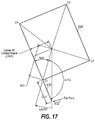
- the film angle FA may be determined by first determining the length of a web of packaging material, e.g., web 630 of FIG. 15 , which extends between an exit point 632 of a packaging material dispenser and corner c 1 of a load 634 .
- the load rotates counterclockwise relative to the dispenser.
- the law of cosines may then be used to determine the film angle as follows:
- FAc ⁇ ⁇ 1 COS - 1 ⁇ ( FLc ⁇ ⁇ 1 2 + Rr 2 - Rc ⁇ ⁇ 1 2 2 * FLc ⁇ ⁇ 1 * R ⁇ ⁇ r ) ( 36 )
- the film angle is likewise calculated as follows:
- FAc ⁇ ⁇ 2 COS - 1 ⁇ ( FLc ⁇ ⁇ 2 2 + Rr 2 - Rc ⁇ ⁇ 2 2 2 * FLc ⁇ ⁇ 2 * R ⁇ ⁇ r ) ( 37 )
- FAc ⁇ ⁇ 3 COS - 1 ⁇ ( FLc ⁇ ⁇ 3 2 + Rr 2 - Rc ⁇ ⁇ 3 2 2 * FLc ⁇ ⁇ 3 * R ⁇ ⁇ r ) ( 38 )
- FAc ⁇ ⁇ 4 COS - 1 ⁇ ( FLc ⁇ ⁇ 4 2 + Rr 2 - Rc ⁇ ⁇ 4 2 2 * FLc ⁇ ⁇ 4 * R ⁇ ⁇ r ) ( 39 )
- the dimensions of the tangent circle, and thus the effective consumption rate may be determined, and equation (9) as discussed above may be used to control the dispense rate.
- the dimensions of the tangent circle may be determined without one or more of the intermediate calculations discussed above.
- film angle does not need to be separately calculated.
- a triangle 636 is defined by the rotation radial, web 630 and the corner radial, each respectively having a length Rr, FLc 1 and Rc 1 .
- the altitude of this triangle is the effective radius of tangent circle 638 .
- R TC 2 * s ⁇ ( s - FLc ⁇ ⁇ 1 ) ⁇ ( s - Rr ) ⁇ ( s - Rc ⁇ ⁇ 1 ) FL ⁇ ⁇ c ⁇ ⁇ 1 ( 40 ) where s, the semiperimeter, is one half the sum of the sides, or (FLc 1 +Rr+Rc 1 )/2.
- a load distance sensor may be used to determine film angle, and thus, effective circumference and/or effective consumption rate.
- a load distance sensor 432 may be oriented along a radius from the center of rotation 408 and at a known and fixed distance from and angular position about the center of rotation. By orienting this sensor such that a corner passes the sensor prior to engaging the packaging material, both the length and the contact angle of the corner radial may be determined prior to contact with the packaging material, and used to control dispense rate through the phase of the rotation in which the web of packaging material extends between the corner and the exit point of the dispenser.
- a corner typically may be identified at a local minimum in the output of load distance sensor 432 , which occurs when the corner passes the sensor.
- the load distance sensor may be used to determine the complete geometric profile of the load, e.g., through an initial full revolution in which the distance to the surface of the load is stored and used to derive the length, width and offset of the load and/or the locations of each of the corners.
- the load distance sensor may be used to determine the complete geometric profile of the load, e.g., through an initial full revolution in which the distance to the surface of the load is stored and used to derive the length, width and offset of the load and/or the locations of each of the corners.
- Derivation of the corner locations e.g., corner radials and corner location angles
- an effective consumption rate and/or effective circumference/radius-based wrap speed model may be employed to control the dispense rate during a wrapping operation.
- film speed e.g., the speed of idle roller 126 as sensed by sensor 150 of FIG. 1 and converted from rotational velocity to linear velocity based on the known radius of the idle roller.
- the amplitudes of the local minimums and maximums of the film speed may be used.
- the amplitude of the peak, or maximum, speed after a corner passes approximates the length of its corner radial
- the amplitude of the minimum speed where a corner passes approximates the length of its contact radial, which is typically the effective radius of the load at corner contact.
- the angle where the peak or maximum speed occurs after a corner passes approximates the corner location angle where the length of the corner radial and the effective radius are approximately equal
- the angle where the minimum speed occurs after a corner passes approximates the contact angle for that corner.
- 12C illustrates the points matching the approximate amplitudes and angles corresponding to the corner radials Rc 1 , Rc 2 , Rc 3 and Rc 4 for corners c 1 , c 2 , c 3 and c 4 , and to the contact radials CRc 1 , CRc 2 , CRc 3 and CRc 4 .
- corner radial length (Rc 1 ) and the contact radial length (CRc 1 ) for corner c 1 for may be determined as follows:
- Rc ⁇ ⁇ 1 ( FS ⁇ max * K 2 ⁇ ⁇ ) ( 41 )
- CRc ⁇ ⁇ 1 ( FS ⁇ min * K 2 ⁇ ⁇ ) ( 42 )
- FS max is the local maximum film speed after a corner passes
- FS min is the local minimum film speed after the corner passes
- K is a constant used to convert film speed units into length/revolution (e.g., if film speed units are in inches/sec, K may be rotation speed in second/revolution). It will be appreciated that K may be determined empirically or may be calculated based upon the dimensions and configuration of the wrapping apparatus and the sensor used to determine the film speed.
- the location of the corner relative to the rotation radial may be determined, for example, as follows:
- Calculation of the corresponding values for corners c 2 , c 3 and c 4 are performed in a similar manner. Derivation of the dimensions and offset of the load from these values may be performed in the manner discussed above, and an effective consumption rate and/or effective circumference/radius-based wrap speed model may be employed to control the dispense rate during a wrapping operation based upon these values.
- the dimensions and/or offset may be manually input by an operator through a user interface with a wrapping apparatus.
- the dimensions and/or offset may be stored in a database and retrieved by the controller of the wrapping apparatus.
- upstream machinery may provide dimensions of the load to the wrapping apparatus prior to arrival, or a bar code or other identification may be provided on the load to be read by the wrapping apparatus and thereby enable retrieval of the dimensions based on the identification.
- a light curtain or other dimensional sensor or sensor array may be used to visually determine the dimensions and/or offset of the load.
- the dimensions and offset may be determined, for example, before the load is conveyed to the wrapping apparatus, or alternatively, after the load has been conveyed to the wrapping apparatus, and prior to or during initiation of a wrapping operation for the load.
- Derivation of the corner locations e.g., corner radials and corner location angles
- an effective consumption rate and/or effective circumference/radius-based wrap speed model may be employed to control the dispense rate during a wrapping operation.
- a wrap speed model and wrap speed control utilizing such a wrap speed model may be based at least in part on rotation angles associated with one or more corners of a load.
- a corner rotation angle may be considered to include an angle or rotational position about a center of rotation that is relative to or otherwise associated with a particular corner of a load.
- a corner rotation angle may be based on a corner location angle for a corner, and represent the angular position of a corner radial relative to a particular base or home position.
- a corner rotation angle may be based on a corner contact angle for an angle, representing an angle at which packaging material first comes into contact with a corner during relative rotation between the load and a packaging material dispenser.
- a corner rotation angle consistent with the invention is not limited to only a corner location angle or a corner contact angle, and that other angles relative to or otherwise associated with a corner may be used in the alternative.
- corner rotation angles may be used in connection with wrap speed control in a number of manners consistent with the invention. For example, in some embodiments corner rotation angles may be used to determine to what corner the packaging material is currently engaging, and thus, what corner is driving the effective consumption rate of the load. In this regard, in some embodiments, multiple corners may be tracked to enable a determination to be made as to when to switch from a current corner to a next corner when controlling dispense rate. In other embodiments, corner rotation angles may be used to anticipate corner contacts and perform controlled interventions, and in still other embodiments, corner rotation angles may be used in the performance of rotational data shifts.
- a rotation angle such as a contact angle of each corner of a load during the relative rotation.
- a contact angle representing the rotational position of the load when the packaging material first contacts a particular corner, may be determined for each corner.
- the contact angles may be sensed using various sensors discussed above, or determined via calculation based on the dimensions/offset of the load and/or corner locations. In addition, the contact angles may be used to effectively determine what corner is driving the wrap speed model, and thus, what corner profile should be used to control dispense rate.
- FIG. 18 illustrates a graph of the ideal dispense rates for corner profiles 650 a , 650 b , 650 c and 650 d for the four corners of the same load depicted in FIGS. 12A-12C .
- the intersections of these profiles, at 652 a , 652 b and 652 c represent the contact angles when the packaging material, which is being driven by one corner, contacts the next corner such that the next corner begins to drive the desired dispense rate of the packaging material.
- the effective circumference and film angle track these profiles and contact angles, and as such, in some embodiments, the contact angles may be sensed using a number of the aforementioned sensors.
- a wrap speed control may be configured to switch from one corner to a next corner based on the anticipated rotational position of each corner as sensed in either of these manners.
- an effective radius or effective circumference may be calculated based upon a current corner and a next corner, such that the contact angle is determined at the angle where the effective radius/effective circumference of the next corner becomes larger than that of the current corner.
- the contact angles may be calculated based on the dimensions of the load.
- the contact angle (CAc 1 ) for corner c 1 represents the angle where corner c 1 intersects the plane between the previous corner c 4 and exit point 632 .
- the contact angle may be calculated, for example, using the length and location angles of the corner radials for the corner at issue and the immediately preceding corner in the rotation (here, Rc 1 , Rc 4 , LAc 1 and LAc 4 ) and the length of the rotation radial (Rr), which are illustrated in FIG. 19B .
- FIG. 19C illustrates two values, Ac 4 c 1 and Lc 4 c 1 , that may be calculated from the aforementioned values.
- Ac 4 c 1 is the angle between the corner location angles for corners c 1 and c 4 :
- Ac 4 c 1 360 ⁇ LA c 4+LA c 1 (41)
- the contact angle CAc 1 for corner c 1 may be isolated from the known and calculated angles:
- the contact angle of each corner may therefore be determined and used to select which corner is currently “driving” the dispensing process, based upon the known angular relationship of the load to the packaging material dispenser at any given time.
- the contact angle may be used to anticipate a contact of the packaging material with a corner so that, for example, a controlled intervention may be performed.
- implementation of a wrap speed model 500 using any of the aforementioned techniques may be used to wrap packaging material around a load during relative rotation between the load and a packaging material dispenser.
- a clamping device e.g., as known in the art, is used to position a leading edge of the packaging material on the load such that when relative rotation between the load and the packaging material dispenser is initiated, the packaging material will be dispensed from the packaging material dispenser and wrapped around the load.
- the packaging material is stretched prior to being conveyed to the load.
- a lift assembly controls the height of the packaging material so that the packaging material is wrapped in a spiral manner around the load from the base of the load to the top.
- Multiple layers of packaging material may be wrapped around the load over multiple passes to increase containment force, and once the desired amount of packaging material is dispensed, the packaging material is severed to complete the wrap.
- an initial revolution may be performed to determine the dimensions of the load, such that corner locations may be determined prior to wrapping and then wrapping may commence using these predetermine corner locations to drive the dispenser rate based on a calculated effective consumption rate.
- no initial revolution may be performed, and either dimensions of the load as input or retrieved from a database may be used to drive the dispenser rate based on the effective consumption rate.
- sensed film angle, sensed film speed, sensed load distance, etc. may be used to calculate effective consumption rate as soon as wrapping is commenced.
- loads may not have a consistent length and width from top to bottom.
- Loads may include different layers of objects or containers having different lengths and/or widths, and some layers may be offset relative to other layers.
- load dimensions calculated during one full revolution may be used for the next full revolution, such that as the lift assembly changes the elevation of the packaging material dispenser, the load dimensions are dynamically updated based on the dimensions sensed at a particular elevation of the packaging material dispenser.
- FIG. 20 One example wrap speed control process 660 , which is based on concurrent tracking of multiple corner locations, is shown in FIG. 20 .
- the first is referred to herein as the “current corner,” which is the corner that is currently driving the dispensing process, in terms of being the corner at which the packaging material is engaging the load.
- the second is referred to herein as the “next corner,” which is the immediately subsequent corner that will engage the load after further revolution of the load relative to the packaging material dispenser.
- These corners are concurrently tracked such that each contact between the packaging material and a new corner can be anticipated or detected, thereby allowing the dispense rate to be controlled appropriately based upon the location of the new corner.
- One manner of anticipating or detecting a corner contact is based on applying a wrap speed model based on the locations of two corners, and comparing the results.
- the effective consumption rate is determined based on the location of the current corner and based on the location of the next corner.
- a corner contact occurs when the effective consumption rate based on the next corner exceeds that of the current corner, as discussed above in connection with FIG. 18 , and as such, block 666 compares these two effective consumption rates. So long as the corner contact has not yet occurred, and the effective consumption rate of the current corner is used to control the dispense rate, block 666 passes control to block 668 to control the dispense rate based on the effective consumption rate for the current corner. Control then returns to block 662 to continue tracking the current and next corners.
- block 666 passes control to block 670 to update the current corner to what was previously the next corner.
- the current corner is corner c 1 and the next corner is c 2
- the effective consumption rate based on corner c 2 exceeds that calculated based on corner c 1
- c 2 becomes the new current corner
- corner c 3 becomes the new next corner.
- Control passes to block 668 to control the dispense rate based on the new current corner.
- the effective circumference, effective radius, film angle, and film speed all track the effective consumption rate.
- blocks 662 , 664 and 666 may alternatively track the corners based on calculating any of these values and compare the results to determine a corner contact.
- a wrap speed control process may be performed by tracking the corner contact angle for a next corner in block 682 , determining the current rotational position of the load in block 684 (e.g., using an angle sensor such as angle sensor 152 of FIG. 1 ), and then determining in block 686 whether the corner contact angle for the next corner has been reached (i.e., where the rotational position of the load matches the corner contact angle). So long as the corner contact has not yet occurred, block 686 passes control to block 688 to control the dispense rate based on the effective consumption rate calculated from the location of the current corner, and control returns to block 682 . Otherwise, if contact has occurred, block 686 passes control to block 690 to set the current corner to the next corner, such that when control is passed to block 688 , the next corner, now the new current corner, is used to determine the dispense rate.
- sensors may have delays in determining a sensed value and drive motors, such as the motor(s) used to drive a packaging dispenser, as well as the other rotating components in the packaging material, typically have rotational inertia to overcome whenever the dispense rate is changed.
- packaging material typically has some degree of elasticity even after prestretching, so some lag will exist before changes in dispense rate propagate through the web of packaging material.
- mechanical sources of fluctuation such as film slippage on idle rollers, out of round rollers and bearings, imperfect mechanical linkages, flywheel effects of downstream non-driven rollers, also exist.
- an intervention is an operation that controls the dispense rate in a predetermined manner based on a predetermined intervention criteria.
- an intervention is an operation that modifies the dispense rate relative to a predicted demand or a dispense rate that has been calculated by a particular wrap model, e.g., a wrap speed model based on effective circumference or effective consumption rate.
- An intervention may also be an operation that modifies the dispense rate relative to another type of wrap model and/or a wrap model based on another type of control input, e.g., a wrap force model based on wrap force or packaging material tension as monitored by a load cell.
- FIG. 22 illustrates an example process 700 that selectively applies one or more controlled interventions at predetermined times or rotational positions relative to a corner contact.
- a corner contact angle for a next corner is determined, e.g., predicted or anticipated (block 702 ) and one or more intervention criteria are determined (block 704 ).
- An intervention criteria may include, for example, an absolute rotational position (e.g., at 75 degrees) or a relative rotational position (e.g., 10 degrees before or after corner contact), and may be relative to a corner contact angle, a corner location angle, or another calculated angle.
- an intervention criteria may be based on absolute or relative times or distances (e.g., 100 ms before or after corner contact).
- start and end criteria may be specified (e.g., start 10 degrees before corner contact and stop at contact), while in other embodiments, a start criteria may be coupled with a duration such that an intervention is applied for a fixed duration of angles, times or distances after being initiated.
- Block 706 the rotational position of the load is determined, e.g., in terms of an angle, a time or distance within a revolution of the load relative to the packaging material dispenser.
- Block 708 determines whether an intervention criteria has been met. If not, block 708 passes control to block 710 to control the dispense rate without the use of an intervention, e.g., in any of the manners discussed above based on effective circumference or effective consumption rate. If the criteria for an intervention is met, however, block 708 passes control to block 712 to instead control dispense rate based on the intervention.
- a number of interventions may be performed. For example, it may be desirable to reduce the dispense rate below a predicted demand as calculated by a wrap speed model a few degrees prior to a corner contact to build wrap force as the corner approaches, e.g., as shown in FIG. 23A .
- the dispense rate may be advanced a few degrees so that the wrap speed model is time shifted to decrease the dispense rate sooner than would otherwise be performed.
- the dispense rate may be set to the dispense rate to be used at the corner contact, only a few degrees early.
- the wrap speed model may be scaled such that the dispense rate is decreased by a certain percentage from that of the wrap speed model as the corner approaches, e.g., as shown in FIG. 23B .
- the wrap speed model may be delayed a few degrees or scaled to otherwise increase the dispense rate above that calculated from the wrap speed model.
- the dispense rate may be set to hold the dispense rate used at the corner contact for a few extra degrees. It may also be desirable in some embodiments to contact a corner at dispense rate that is a factor less than the dispense rate calculated from the wrap speed model to create a force spike at the corner contact.
- the dispense rate calculated from an example wrap speed model is illustrated at 720 , and as shown at 722 , interventions may be applied to essentially switch between the maximum calculated dispense rate for a corner at or a few degrees after the contact with that corner, and then switch to the minimum calculated dispense rate for that corner a few degrees after the peak has passed.
- an intervention may be used to effectively modify a wrap speed model to improve performance, e.g., by improving containment force and/or reducing the risk of breakage.
- some interventions may be selected to increase force immediately prior to a corner and increase containment force, while other interventions may be selected to relieve force immediately after a corner contact to reduce breakage risk and otherwise ensure that wrap forces built up in the corner are not wasted after the corner contact has occurred.
- multiple interventions may be applied or combined, and that different interventions may be applied to different corners or at different times in the wrapping operation, and that interventions may be tailored for particular corners based on the dimensions of the load.
- interventions may be applied to wrap models other than effective circumference-based wrap speed models, e.g., wrap force models.
- a rotational shift of the data utilized by a wrap speed model may also be desired to account for system lags through the use of a rotational shift of the data utilized by a wrap speed model.
- electrical and physical delays in sensors, drive motors, control circuitry and even the packaging material necessarily introduce a system lag, such that a desired dispense rate at a particular rotational position of the load, as calculated by a wrap speed model, will not occur at the load until after some duration of time or further angular rotation.
- a rotational shift typically may be applied to the sensed data used by the wrap speed model or to the calculated dimensions or position of the load, which in either case has the net effect of advancing the wrap speed model to an earlier point in time or rotational position such that the actual dispense rate at the load will more closely line up with that calculated by the wrap speed model, thereby aligning the phase of the profile of the actual dispense rate with that of the desired dispense rate calculated by the wrap speed model.
- the system lag from which the rotational shift may be calculated may be a fixed value determined empirically for a particular wrapping apparatus.
- the system lag may have both fixed and variable components, and as such, may be derived based upon one or more operating conditions of the wrapping apparatus.
- a controller will typically have a fairly repeatable electronic delay associated with computational and communication costs, which may be assumed in many instances to be a fixed delay.
- the rotational inertia of packaging material dispenser components, different packaging material thicknesses and compositions, and the wrapping speed may contribute variable delays depending upon the current operating condition of a wrapping apparatus.
- the system lag may be empirically determined or may be calculated as a function of one or more operating characteristics.
- a calculated wrap speed model may calculate a desired dispense rate having a profile 714 , yet due to system lag, if that profile is applied to control the dispense rate of a packaging material dispenser, the actual profile 716 a may be delayed relative to the desired profile 714 .
- the resulting actual profile 716 b more closely approximates the desired profile 714 .
- a rotational shift may be performed, for example, in the manner illustrated by process 720 of FIG. 25 , which is similar to process 680 of FIG. 21 .
- Process 720 may begin in block 722 by determining the geometry of the load, e.g., the dimensions, offset and/or corner locations. In one embodiment, for example, an initial revolution of the load may be performed, while in another embodiment, the dimensions of the load may be input or retrieved from a database. Alternatively, the geometry may be determined during wrapping via any of the sensed inputs discussed above.
- the system lag is determined.
- the system lag may be a fixed value, and in other embodiments, the system lag may be a variable value that may be calculated, for example, based on wrapping speed. In still other embodiments, system lag may be determined dynamically during wrapping, e.g., so that a system lag determined during one revolution is used to perform a rotational shift in one or more subsequent revolutions.
- process 720 proceeds by tracking the corner contact angle for a next corner in block 726 , determining the current rotational position of the load in block 728 (e.g., using an angle sensor such as angle sensor 152 of FIG. 1 ), and then performing a rotational shift of either the corner contact angle (by subtracting from the calculated corner contact angle) or the current rotational position of the load (by adding to the sensed rotational position) to offset the system lag in block 730 . Thereafter, block 732 determines whether the corner contact angle for the next corner has been reached, but in this case, the comparison incorporates the rotational shift such that the corner contact is detected earlier than would otherwise occur based on the wrap speed model.
- block 732 passes control to block 734 to control the dispense rate based on the effective consumption rate calculated from the location of the current corner, and control returns to block 726 .
- the wrap speed model is effectively advanced to offset the system lag.
- control is passed to block 736 to set the current corner to the next corner, such that when control is passed to block 734 , the next corner, now the new current corner, is used to determine the dispense rate, again with the rotational shift accounted for in the wrap speed model.
- Rotational shifts may also be applied in other manners consistent with the invention. For example, through positioning of a sensor such as a load distance sensor at an earlier rotational position, e.g., shifted a few degrees in advance of a base or home position, the sensor data may be treated as if it were collected at the base or home position to apply a rotational shift to the model.
- a sensor such as a load distance sensor
- the sensor data may be treated as if it were collected at the base or home position to apply a rotational shift to the model.
- Embodiments of the invention may be used, for example, to increase containment force applied to a load by packaging material, and moreover, reduce fluctuations in wrap force that may occur during a wrapping operation, particularly at higher wrapping speeds.
- the difference between the maximum applied wrap forces, which might otherwise cause packaging material breakages, and the minimum applied wrap forces, which affect the overall containment force that may be achieved may be reduced, enabling improved containment forces to be achieved with reduced risk of breakages.
- reducing the force fluctuations will permit higher containment forces to be obtained with thinner packaging material, with increased prestretch and/or with less packaging material (e.g., through the use of fewer layers).
- containment forces are more consistent across all corners and sides of the load.
- any sequence or combination of the above-described methods may be performed during the wrapping of one or more loads. For example, while wrapping a load, one method may be performed, whereas while wrapping another load, another method may be performed. Additionally or alternatively, while wrapping a single load, two or more of the three methods may be performed. One method may be performed during one portion of the wrapping cycle, and another method may be performed during another portion of the wrapping cycle. Additionally or alternatively, one load may be wrapped using a first combination of methods, while another load may be wrapped using a second combination of methods (e.g., a different combination of methods, and/or a different sequence of methods).
Abstract
Description
L d=2π*R d *N d (1)
L f=2π*R f *N f (2)
where Ld is the length of belt that passes over the driver pulley in one minute, and Lf is the length of belt that passes over the follower pulley in one minute.
2π*R d *N d=2π*R f *N f (3)
where Df, Dd are the respective diameters of the follower and driver pulleys, and Cf, Cd are the respective circumferences of the follower and driver pulleys.
ECR=C TC *N TC=2π*R TC *N TC (7)
where CTC is the circumference of the tangent circle, NTC is the rotational velocity of the tangent circle (e.g., in revolutions per minute (RPM)), and RTC is the radius of the tangent circle.
where NDR is the rotational rate of the drive roller, CTC is the circumference of the tangent circle and the effective circumference of the load, CDR is the circumference of the drive roller and NL is the rotational rate of the load relative to the dispenser.
R TC=RR*sin(FA) (10)
C TC=2π*R TC=2π*RR*sin(FA) (11)
L=√{square root over (Rc42 +Rc12−2*Rc4*Rc1*cos(Ac4c1))} (12)
where
L=√{square root over (Rc22 +Rc32−2*Rc2*Rc3*cos(Ac2c3))} (13)
where
W=√{square root over (Rc32 +Rc42−2*Rc3*Rc4*cos(Ac3c4))} (14)
L=√{square root over (Rc12 +Rc22−2*Rc1*Rc2*cos(Ac1c2))} (15)
where
LAc2=LAc1+LAc2a+LAc2b (21)
FLc1=√{square root over (Rc12 +Rr 2−2*Rc1*Rr*cos(Ac1))} (32)
where Ac1=RA−LAc1.
FLc2=√{square root over (Rc22 +Rr 2−2*Rc2*Rr*cos(Ac2))} (33)
FLc3=√{square root over (Rc32 +Rr 2−2*Rc3*Rr*cos(Ac3))} (34)
FLc4=√{square root over (Rc42 +Rr 2−2*Rc4*Rr*cos(Ac4))} (35)
where Ac2=RA−LAc2, Ac3=RA−LAc4, and Ac4=RA−LAc4.
where s, the semiperimeter, is one half the sum of the sides, or (FLc1+Rr+Rc1)/2.
where FSmax is the local maximum film speed after a corner passes, FSmin is the local minimum film speed after the corner passes, and K is a constant used to convert film speed units into length/revolution (e.g., if film speed units are in inches/sec, K may be rotation speed in second/revolution). It will be appreciated that K may be determined empirically or may be calculated based upon the dimensions and configuration of the wrapping apparatus and the sensor used to determine the film speed.
where Lac1Rr is the difference between the corner location and corner contact angles for the corner.
Ac4c1=360−LAc4+LAc1 (41)
Lc4c1=√{square root over (Rc42 +Rc12−2*Rc4*Rc1*cos(Ac4c1))} (42)
Ac1c2=LAc2−LAc1 (48)
CAc2=LAc1+Ac1Rr (49)
Claims (27)
Priority Applications (1)
| Application Number | Priority Date | Filing Date | Title |
|---|---|---|---|
| US16/017,602 US11111045B2 (en) | 2012-10-25 | 2018-06-25 | Dynamic rotation angle-based wrapping |
Applications Claiming Priority (4)
| Application Number | Priority Date | Filing Date | Title |
|---|---|---|---|
| US201261718433P | 2012-10-25 | 2012-10-25 | |
| US201261718429P | 2012-10-25 | 2012-10-25 | |
| US14/062,929 US10005580B2 (en) | 2012-10-25 | 2013-10-25 | Rotation angle-based wrapping |
| US16/017,602 US11111045B2 (en) | 2012-10-25 | 2018-06-25 | Dynamic rotation angle-based wrapping |
Related Parent Applications (1)
| Application Number | Title | Priority Date | Filing Date |
|---|---|---|---|
| US14/062,929 Continuation US10005580B2 (en) | 2012-10-25 | 2013-10-25 | Rotation angle-based wrapping |
Publications (2)
| Publication Number | Publication Date |
|---|---|
| US20180305055A1 US20180305055A1 (en) | 2018-10-25 |
| US11111045B2 true US11111045B2 (en) | 2021-09-07 |
Family
ID=49551804
Family Applications (3)
| Application Number | Title | Priority Date | Filing Date |
|---|---|---|---|
| US14/062,929 Active 2035-05-27 US10005580B2 (en) | 2012-10-25 | 2013-10-25 | Rotation angle-based wrapping |
| US16/017,590 Active 2034-05-27 US11104464B2 (en) | 2012-10-25 | 2018-06-25 | Rotation angle-based wrapping of loads with varying dimensions |
| US16/017,602 Active 2034-06-03 US11111045B2 (en) | 2012-10-25 | 2018-06-25 | Dynamic rotation angle-based wrapping |
Family Applications Before (2)
| Application Number | Title | Priority Date | Filing Date |
|---|---|---|---|
| US14/062,929 Active 2035-05-27 US10005580B2 (en) | 2012-10-25 | 2013-10-25 | Rotation angle-based wrapping |
| US16/017,590 Active 2034-05-27 US11104464B2 (en) | 2012-10-25 | 2018-06-25 | Rotation angle-based wrapping of loads with varying dimensions |
Country Status (5)
| Country | Link |
|---|---|
| US (3) | US10005580B2 (en) |
| EP (1) | EP2917112B1 (en) |
| AU (1) | AU2013334151B2 (en) |
| CA (1) | CA2889570C (en) |
| WO (1) | WO2014066757A1 (en) |
Families Citing this family (22)
| Publication number | Priority date | Publication date | Assignee | Title |
|---|---|---|---|---|
| EP2244947B1 (en) | 2008-01-07 | 2015-10-14 | Lantech.Com, Llc | Electronic control of metered film dispensing in a wrapping apparatus |
| US9908648B2 (en) | 2008-01-07 | 2018-03-06 | Lantech.Com, Llc | Demand based wrapping |
| US9493262B2 (en) | 2010-10-29 | 2016-11-15 | Lantech.Com, Llc | Machine generated wrap data |
| EP3269653B1 (en) | 2012-10-25 | 2022-05-18 | Lantech.com, LLC | Corner geometry-based wrapping |
| US10005581B2 (en) | 2012-10-25 | 2018-06-26 | Lantech.Com, Llc | Effective circumference-based wrapping |
| CA2889570C (en) | 2012-10-25 | 2020-10-27 | Lantech.Com, Llc | Rotation angle-based wrapping |
| US10239645B2 (en) | 2013-02-13 | 2019-03-26 | Lantech.Com, Llc | Packaging material profiling for containment force-based wrapping |
| US9896229B1 (en) | 2013-08-29 | 2018-02-20 | Top Tier, Llc | Stretch wrapping apparatus and method |
| CA3111412C (en) | 2014-01-14 | 2023-08-08 | Lantech.Com, Llc | Dynamic adjustment of wrap force parameter responsive to monitored wrap force and/or for film break reduction |
| CA2964112C (en) | 2014-10-07 | 2021-07-06 | Lantech.Com, Llc | Load stability-based wrapping |
| WO2016164776A1 (en) * | 2015-04-10 | 2016-10-13 | Lantech.Com, Llc | Stretch wrapping machine supporting top layer containment operations |
| AU2016326540B2 (en) | 2015-09-25 | 2019-07-25 | Lantech.Com, Llc | Stretch wrapping machine with automated determination of load stability by subjecting a load to a disturbance |
| GB2552214A (en) * | 2016-07-14 | 2018-01-17 | Kuhn-Geldrop Bv | Bale wrapper and method of applying stretch film wrapping to an agricultural bale |
| US11565842B2 (en) | 2017-09-22 | 2023-01-31 | Lantech.Com, Llc | Packaging material quality compensation |
| EP3684698B1 (en) | 2017-09-22 | 2023-11-15 | Lantech.com, LLC | Load wrapping apparatus wrap profiles with controlled wrap cycle interruptions |
| US11136151B1 (en) * | 2018-04-23 | 2021-10-05 | Michael Baker | Orbital wrapping machine |
| CA3106566C (en) | 2018-08-06 | 2023-04-04 | Lantech.Com, Llc | Stretch wrapping machine with curve fit control of dispense rate |
| WO2020081940A1 (en) | 2018-10-18 | 2020-04-23 | Lantech.Com, Llc | Stretch wrapping machine with variable frequency drive torque control |
| EP3941868A4 (en) | 2019-03-20 | 2023-03-22 | Lantech.Com, Llc | Packaging material evaluation and apparatus therefor for sensing packaging material flaws |
| WO2021050420A1 (en) * | 2019-09-09 | 2021-03-18 | Lantech.Com, Llc | Stretch wrapping machine with dispense rate control based on sensed rate of dispensed packaging material and predicted load geometry |
| US11520026B2 (en) * | 2019-09-19 | 2022-12-06 | Lantech.Com, Llc | Ultrasonic packaging material flaw detection with time-limited response detection |
| EP4031455A4 (en) | 2019-09-19 | 2024-04-03 | Lantech Com Llc | Packaging material grading and/or factory profiles |
Citations (187)
| Publication number | Priority date | Publication date | Assignee | Title |
|---|---|---|---|---|
| US2227398A (en) | 1939-07-14 | 1940-12-31 | Micro Westco Inc | Wrapping material measuring device |
| US2904196A (en) | 1957-07-16 | 1959-09-15 | Frank M Teixeira | Loading and unloading apparatus for vehicles |
| US3029571A (en) | 1960-08-16 | 1962-04-17 | Du Pont | Apparatus for dispensing wrapping materials |
| US3707658A (en) | 1969-05-22 | 1972-12-26 | Westinghouse Electric Corp | Stretch control system for elongate material |
| US3815313A (en) | 1972-10-04 | 1974-06-11 | R Heisler | Apparatus and method for automatically sizing and wrapping a shrink wrap envelope around advancing luggage |
| US3910005A (en) | 1972-11-24 | 1975-10-07 | Applic Thermiques | Process and machine for packing |
| US4152879A (en) | 1977-06-21 | 1979-05-08 | Shulman Michael H | Spiral-wrap apparatus |
| GB1546523A (en) | 1977-10-07 | 1979-05-23 | Inpac Automation Ltd | Stretch wrapping apparatus |
| US4216640A (en) | 1978-06-12 | 1980-08-12 | Kaufman Charles R | Unit load wrapping machine |
| US4235062A (en) | 1978-07-26 | 1980-11-25 | Lantech Inc. | Collapsible web wrapping apparatus |
| GB2059906A (en) | 1979-09-12 | 1981-04-29 | Lancaster W G | A process and apparatus for wrapping loads in stretch films |
| US4271657A (en) | 1978-07-26 | 1981-06-09 | Lantech Inc. | Automatic web tying apparatus |
| US4300326A (en) | 1980-03-10 | 1981-11-17 | Lantech Inc. | Stretch wrapping apparatus with mechanical closure |
| DE3140972A1 (en) | 1980-10-27 | 1982-06-03 | Michael H. Willowdale Ontario Shulman | Prestressing device for foil webs |
| US4344269A (en) | 1978-06-12 | 1982-08-17 | R. A. Jones & Co. Inc. | Pouch forming and filling mechanism with provision for increasing the capacity of the pouches |
| JPS57166252A (en) | 1981-03-31 | 1982-10-13 | Infura Patsuku Darasu Inc | Automatic winder for film material |
| DE3119038A1 (en) | 1981-05-13 | 1982-12-02 | Dentz Palettenverpackung GmbH Verpackungsmaschinen und Gerätebau, 7012 Fellbach-Oeffingen | Apparatus for packaging pallets with stretch wrapping foil |
| GB2107668A (en) | 1981-10-13 | 1983-05-05 | Inpac Automation Limited | Stretch wrapping apparatus |
| US4387548A (en) | 1979-11-21 | 1983-06-14 | Lantech, Inc. | Power assisted roller-stretch wrapping process |
| US4395255A (en) | 1980-09-17 | 1983-07-26 | Pitney Bowes Inc. | Web folding apparatus |
| US4418510A (en) | 1979-09-12 | 1983-12-06 | Lantech, Inc. | Stretch wrapping apparatus and process |
| EP0096635A2 (en) | 1982-06-07 | 1983-12-21 | Procter & Gamble European Technical Center | Method and device for regulating the pre-stretching of a plastic film, especifically in view of the packaging of a load |
| US4429514A (en) | 1979-11-21 | 1984-02-07 | Lantech, Inc. | Rotatable stretching apparatus with prestretching mechanism |
| US4432185A (en) | 1981-09-01 | 1984-02-21 | Wolfgang Geisinger | Pallet wrapper |
| US4497159A (en) | 1982-02-01 | 1985-02-05 | Lantech, Inc. | Friction drive stretch wrapping apparatus |
| US4501105A (en) | 1982-04-26 | 1985-02-26 | Hobart Corporation | Film supply monitor for film wrapping machine |
| US4503658A (en) | 1981-04-06 | 1985-03-12 | Lantech, Inc. | Feedback controlled stretch wrapping apparatus and process |
| US4505092A (en) | 1982-04-26 | 1985-03-19 | Hobart Corporation | Package sensing/film control system for film wrapping machine |
| US4514955A (en) | 1981-04-06 | 1985-05-07 | Lantech, Inc. | Feedback controlled stretch wrapping apparatus and process |
| EP0144266A2 (en) | 1983-12-01 | 1985-06-12 | EMCO INTERNATIONAL Société dite: | Device for wrapping a load with a stretchable plastic film |
| US4524568A (en) | 1982-08-27 | 1985-06-25 | Lantech, Inc. | Power assisted rotatable film wrapping apparatus |
| US4590746A (en) | 1981-09-30 | 1986-05-27 | International Packaging Machines, Inc. | Constant tension stretch wrapping machine |
| US4628667A (en) | 1981-02-19 | 1986-12-16 | International Packaging Machines, Inc. | Variable speed stretch wrapper |
| US4676048A (en) | 1984-02-23 | 1987-06-30 | Lantech, Inc. | Supply control rotating stretch wrapping apparatus and process |
| US4693049A (en) | 1982-05-04 | 1987-09-15 | International Packaging Machines, Inc. | Stretch wrapping machine |
| EP0246659A1 (en) | 1986-05-23 | 1987-11-25 | Mima Incorporated | Multi-stage prestretch wrapping apparatus and method |
| US4712354A (en) | 1984-02-23 | 1987-12-15 | Lantech, Inc. | Dual rotating stretch wrapping apparatus and process |
| US4716709A (en) | 1986-10-06 | 1988-01-05 | Howard City Paper Company | Apparatus and method for roll wrapping with poly-coated paper |
| JPS634993A (en) | 1986-06-16 | 1988-01-09 | ヘキスト・セラニーズ・コーポレイシヨン | Fountain solution for plate |
| US4736567A (en) | 1987-03-02 | 1988-04-12 | Automatic Handling, Inc. | Wrapping machine |
| DE3634924A1 (en) | 1986-10-14 | 1988-04-21 | Dentz Verpackungsmaschinen Gmb | Packaging apparatus for foil-wrapped packs |
| US4754594A (en) | 1980-02-27 | 1988-07-05 | Lantech, Inc. | Z-stretch wrapping system |
| US4761934A (en) | 1987-02-27 | 1988-08-09 | Lantech | Parallel belted clamp |
| JPS63191707A (en) | 1987-02-02 | 1988-08-09 | 松本 良三 | Packer |
| US4807427A (en) | 1988-04-21 | 1989-02-28 | Liberty Industries, Inc. | Stretch wrapping roping apparatus |
| US4840006A (en) | 1981-09-30 | 1989-06-20 | International Packaging Machines, Inc. | Stretch wrapping machine |
| US4845920A (en) | 1980-02-27 | 1989-07-11 | Lantech, Inc. | Roped stretch wrapping system |
| US4855924A (en) | 1987-05-14 | 1989-08-08 | Ford New Holland, Inc. | Round baler with continuous bale size monitoring |
| US4862678A (en) | 1981-09-30 | 1989-09-05 | International Packaging Machines, Inc. | Constant tension stretch wrapping machine |
| US4866909A (en) | 1985-12-04 | 1989-09-19 | Lantech, Inc. | High tensile wrapping process |
| US4905451A (en) | 1987-06-26 | 1990-03-06 | Newtec International | Strip having a longitudinal reinforcement, its production and its use in a packaging method, and a device for the production of such a strip |
| DE3901704A1 (en) | 1989-01-21 | 1990-08-02 | Weber Hans Juergen | Process and apparatus for wrapping the vertical sides of material to be packaged |
| US4953336A (en) | 1984-02-23 | 1990-09-04 | Lantech, Inc. | High tensile wrapping apparatus |
| US4991381A (en) | 1989-06-07 | 1991-02-12 | Liberty Industries | Stretch wrapped braking apparatus |
| JPH0385209A (en) | 1989-08-18 | 1991-04-10 | Tsuchiya Kikai Seisakusho:Kk | Film winding device |
| WO1991007341A1 (en) | 1989-11-15 | 1991-05-30 | John Burdon | The automatic adjustment of tension in material drawn off a roll |
| US5027579A (en) | 1989-05-31 | 1991-07-02 | Keip Machine Company | Wrapping apparatus |
| US5040356A (en) | 1985-04-29 | 1991-08-20 | Newtech Packing Equipment Corp. | Method of wrapping a load with stretchable plastic material |
| US5040359A (en) | 1989-08-02 | 1991-08-20 | Newtec International (Societe Anonyme) | Method and machine for banding a palletized load |
| US5054263A (en) | 1989-01-04 | 1991-10-08 | Insinooritoimisto Pesmel Oy | Method and apparatus for wrapping a plastic film around a load |
| US5054987A (en) | 1985-05-29 | 1991-10-08 | Valcomatic Systems, Inc. | Load transfer device |
| US5081824A (en) | 1989-09-06 | 1992-01-21 | Newtec International (Societe Anonyme) | Film unwinding carriage for a packaging machine |
| EP0466980A1 (en) | 1990-07-17 | 1992-01-22 | The Procter & Gamble Company | Palletized loads wrapped with stretchable film, process and apparatus for making them |
| US5107657A (en) | 1991-04-30 | 1992-04-28 | Mima Incorporated | Wrapping apparatus and related wrapping methods |
| US5123230A (en) | 1989-12-19 | 1992-06-23 | B. Hagemann Gmbh & Co. | Method and apparatus for wrapping articles in plastic |
| US5138817A (en) | 1991-04-01 | 1992-08-18 | Prim Hall Enterprises, Inc. | Method of and system for creating a uniform log of strapped bundles |
| US5163264A (en) | 1990-06-06 | 1992-11-17 | Develog, Reiner Hannen & Cie | Apparatus for winding a stretchable foil around a stack of articles |
| US5186981A (en) | 1984-10-26 | 1993-02-16 | Lantech, Inc. | Rollers for prestretch film overwrap |
| US5195297A (en) | 1980-02-27 | 1993-03-23 | Lantech, Inc. | Unitized display packages and method and apparatus for utilizing display packages |
| US5195296A (en) | 1991-08-09 | 1993-03-23 | Ryozo Matsumoto | Wrapping method |
| US5195301A (en) | 1991-07-11 | 1993-03-23 | Newtec International (Societe Anonyme) | Method and machine for wrapping the vertical lateral and upper end faces of a palletized load |
| US5203139A (en) | 1991-06-28 | 1993-04-20 | Eastman Kodak Company | Apparatus and method for winding and wrapping rolls of web material |
| US5203136A (en) | 1989-09-06 | 1993-04-20 | Newtec International (Societe Anonyme) | Film unwinding carriage for a packaging machine |
| US5216871A (en) | 1991-04-24 | 1993-06-08 | Develog, Reiner Hannen & Cie | System for wrapping palletized goods |
| US5240198A (en) | 1991-11-29 | 1993-08-31 | Beloit Technologies, Inc. | Compliant roller for a web winding machine |
| US5301493A (en) | 1992-09-25 | 1994-04-12 | Chen Tsung Yen | Steplessly adjustable pre-stretched film wrapping apparatus |
| DE4234604A1 (en) | 1992-10-14 | 1994-04-21 | Hagemann B Gmbh & Co | Packing machine for wrapping objects in stretch foil - has hydraulic system connected to wrapping device to compensate tension of stretch foil. |
| US5311725A (en) | 1992-07-30 | 1994-05-17 | Lantech, Inc. | Stretch wrapping with tension control |
| US5315809A (en) | 1992-09-11 | 1994-05-31 | Lantech, Inc. | Stretch wrapping emergency stop |
| JPH06239311A (en) | 1993-02-05 | 1994-08-30 | Fuji Mach Co Ltd | Method and device for film feeding controlling of vertical bagging/packing machine |
| WO1994020367A1 (en) | 1993-03-12 | 1994-09-15 | Kenneth Stephen Eddin Orpen | Hydraulic bale wrapper |
| US5369416A (en) | 1992-06-17 | 1994-11-29 | Indikon Company, Inc. | Multi-color bargraph |
| US5414979A (en) | 1993-04-23 | 1995-05-16 | Lantech, Inc. | Stretch wrapping apparatus |
| EP0653352A1 (en) | 1993-11-17 | 1995-05-17 | Burtech Ab | Incrementally variable transmission between prestretching rollers in a stretch-film wrapping machine |
| US5447008A (en) | 1990-07-16 | 1995-09-05 | Newtec International (Societe Anonyme) | Method and machine for wrapping the side face and one end face of a load |
| EP0671324A1 (en) | 1994-03-08 | 1995-09-13 | Lantech, Inc. | Process for stretch wrapping with film severing |
| US5463842A (en) | 1991-08-19 | 1995-11-07 | Lantech, Inc. | Method and apparatus for stretch wrapping the top and sides of a load |
| JPH085448Y2 (en) | 1988-12-19 | 1996-02-14 | オリンパス光学工業株式会社 | Zoom lens drive mechanism for stereo microscope |
| US5524413A (en) | 1994-02-21 | 1996-06-11 | Ishida Co., Ltd. | Packaging machine with device for monitoring remaining amount of web in a roll |
| US5546730A (en) | 1994-03-31 | 1996-08-20 | Lantech, Inc. | Method and apparatus for placing corner boards and stretch wrapping a load |
| DE19509649A1 (en) | 1995-03-17 | 1996-09-19 | Nuetro Maschinen & Anlagen | Film end fixing method for stretch wrapping of good stacks |
| US5572855A (en) | 1995-01-09 | 1996-11-12 | Liberty Industries | Stretch wrapping tape dispensing apparatus |
| US5581979A (en) | 1994-12-19 | 1996-12-10 | Mima Incorporated | Method and apparatus for applying a constant tension to a film |
| WO1997000202A1 (en) | 1995-06-16 | 1997-01-03 | Kenneth Stephen Eddin Orpen | Improved wrapping methods and apparatus |
| US5595042A (en) | 1993-03-24 | 1997-01-21 | A.W.A.X. Progettazione E Ricerca S.R.L. | Process and machine for wrapping products with stretchable film, and wrapping formed by this process |
| US5634321A (en) | 1994-04-07 | 1997-06-03 | Newtec International | Optimized method of applying an outer wrapping, and of transporting a wrapped load |
| US5653093A (en) | 1994-12-05 | 1997-08-05 | A.W.A.X Progettazione E Ricerca S.R.L. | Method and apparatus to maintain the characteristics of a thermoplastic film at constant values |
| JPH09254913A (en) | 1996-03-28 | 1997-09-30 | Oji Seitai Kk | Spiral type stretch packaging machine |
| US5671593A (en) | 1995-12-28 | 1997-09-30 | Wrap-It-Up, Inc. | Semiautomatic package wrapping machine |
| EP0811554A1 (en) | 1996-05-06 | 1997-12-10 | ROBOPAC SISTEMI S.r.l. | Apparatus for the wrapping of palletized product groups with plastic film |
| EP0842850A2 (en) | 1996-11-13 | 1998-05-20 | Lantech Technology Investment Corp. | Apparatus and method for wrapping a load while controlling wrap tension |
| WO1998022346A1 (en) | 1996-11-18 | 1998-05-28 | Officina Meccanica Sestese S.P.A. | Epicycloidal wrapping machine for pallets |
| US5765344A (en) | 1997-02-21 | 1998-06-16 | Wulftec International Inc. | Stretch wrapping film cut-off system |
| US5797246A (en) | 1995-12-13 | 1998-08-25 | Thimon, S.A. | Pre-stretched film, and apparatus and a method for outer packaging |
| US5799471A (en) | 1996-09-26 | 1998-09-01 | Chen; Tsung-Yen | Steplessly adjustable pre-stretched film wrapping apparatus |
| US5875617A (en) | 1997-10-24 | 1999-03-02 | Illinois Tool Works Inc. | Overhead rotating type stretch film wrapping machine support beam structure |
| US5884453A (en) | 1995-05-18 | 1999-03-23 | The Dow Chemical Company | Low-noise film unwrapping and device |
| US5893258A (en) | 1996-12-20 | 1999-04-13 | Lantech Technology Investment Corp. | Building and wrapping a stabilized load |
| JPH11165705A (en) | 1997-11-28 | 1999-06-22 | Oji Seitai Kk | Spiral-type stretch-wrap packaging machine |
| US5941049A (en) | 1997-03-24 | 1999-08-24 | Lantech, Inc. | Method and apparatus for stretch wrapping a load |
| US6082081A (en) | 1998-07-10 | 2000-07-04 | Mucha; Jacek | Powered prestretched film delivery apparatus |
| US6185900B1 (en) | 1999-04-15 | 2001-02-13 | Lantech Management Corp. | Method and apparatus for stretch wrapping a load |
| JP2001048111A (en) | 1999-08-10 | 2001-02-20 | Sekisui Jushi Co Ltd | Stretch packagaging machine |
| US6195968B1 (en) | 1999-07-08 | 2001-03-06 | Wulftec International Inc. | Apparatus for wrapping a load |
| JP2001072012A (en) | 1999-09-01 | 2001-03-21 | Sekisui Jushi Co Ltd | Stretch-wrap packaging machine |
| US6253532B1 (en) | 1996-12-18 | 2001-07-03 | Kenneth Stephen Eddin Orpen | Wrapping apparatus |
| EP1125841A1 (en) | 2000-02-17 | 2001-08-22 | Oy M. Haloila Ab | Apparatus for winding a wrapping film about an article |
| US6293074B1 (en) | 1998-02-20 | 2001-09-25 | Lantech Management Corp. | Method and apparatus for stretch wrapping a load |
| US6314333B1 (en) | 1998-07-03 | 2001-11-06 | Kimberly-Clark Worldwide, Inc. | Method and apparatus for controlling web tension by actively controlling velocity and acceleration of a dancer roll |
| US6338480B1 (en) | 1999-02-26 | 2002-01-15 | Tohoku Ricoh Co., Ltd. | Sheet feeding device for an image forming apparatus |
| US20020029540A1 (en) | 2000-06-13 | 2002-03-14 | Lancaster Patrick R. | Method and apparatus for wrapping a top and bottom of a load |
| US6360512B1 (en) | 1999-10-27 | 2002-03-26 | Wulftec International Inc. | Machine and method for fastening a load |
| US6370839B1 (en) | 1999-08-10 | 2002-04-16 | Sekisui Jushi Kabushiki Kaisha | Stretch wrapping machine |
| EP1213223A1 (en) | 2000-11-14 | 2002-06-12 | OFFICINA MECCANICA SESTESE S.p.A. | Device for unwinding stretchable plastic film |
| JP2002211503A (en) | 2001-01-18 | 2002-07-31 | Gunze Ltd | Packaging apparatus using drawn film |
| US6453643B1 (en) | 1997-12-10 | 2002-09-24 | Pieri S.R.L. | Method and apparatus for the fastening of the tail of wrappings of stretchable film for palletized loads |
| US20030089081A1 (en) | 2001-11-09 | 2003-05-15 | Lely Enterprises. A.G., A Swiss Limited Liability Company | Device and method for wrapping bodies, in particular bales of harvested material |
| US20030110737A1 (en) * | 2001-11-01 | 2003-06-19 | Lancaster Patrick R. | Method and apparatus for wrapping a load |
| US20030145563A1 (en) | 2001-04-27 | 2003-08-07 | Mauro Cere' | Apparatus for wrapping products with plastic film |
| US20030200732A1 (en) | 2002-04-30 | 2003-10-30 | Pesmel Oy | Film feeding device and an automatic wrapping device |
| US20030200731A1 (en) | 2002-04-30 | 2003-10-30 | Pesmel Oy | Wrapping device with a circular track structure, and a film feeding device |
| US6684612B2 (en) | 2000-03-08 | 2004-02-03 | Illinois Tool Works Inc. | Machine for wrapping a load with a device for pleating a width of film |
| US20040031238A1 (en) | 2000-10-09 | 2004-02-19 | Cox Bruce Naylor | Method and apparatus for wrapping a load |
| US6698161B1 (en) | 1999-03-26 | 2004-03-02 | Robopac S.A. | Device for loading film on machines for wrapping products |
| US20040040477A1 (en) | 2002-06-15 | 2004-03-04 | Neumann Kenneth M. | Truck platform for 463L pallets |
| JP2004161344A (en) | 2002-11-14 | 2004-06-10 | Sekisui Jushi Co Ltd | Stretch packaging machine |
| WO2004069659A1 (en) | 2003-01-31 | 2004-08-19 | Lantech.Com, Llc | Method and apparatus for securing a load to a pallet with a roped film web |
| US20040177592A1 (en) | 2002-11-01 | 2004-09-16 | Lancaster Patrick R. | Method and apparatus for securing a tail of film to a load |
| EP1489004A2 (en) | 2003-06-16 | 2004-12-22 | Illinois Tool Works Inc. | Wrapping apparatus |
| US6848240B2 (en) | 2001-12-26 | 2005-02-01 | Illinois Tool Works Inc. | Stretch head for facilitating wrapping palletized loads |
| JP3634993B2 (en) | 1999-11-30 | 2005-03-30 | シグノード株式会社 | Film feeding unit |
| US20050115202A1 (en) | 2003-10-10 | 2005-06-02 | Mertz William J.Ii | Method and apparatus for packaging panel products |
| US20060028969A1 (en) | 2002-06-04 | 2006-02-09 | Victor Company Of Japan, Limited | Information recording medium, and apparatuses for reproducing, recording, and recording and reproducing thereof, and methods for reproducing, recording, and recording and reproducing thereof |
| WO2006032065A1 (en) | 2004-09-16 | 2006-03-23 | Gavin Weir | An apparatus for wrapping goods on a pallet |
| EP1705119A1 (en) | 2005-03-25 | 2006-09-27 | Atlanta Stretch s.p.a. | Ring machine for wrapping loads with stretch film |
| WO2006110596A1 (en) | 2005-04-08 | 2006-10-19 | Lantech.Com, Llc | Method and apparatus for dispensing a predetermined fixed amount of pre-stretched film relative to load girth |
| EP1717149A1 (en) | 2005-04-21 | 2006-11-02 | Atlanta Stretch s.p.a. | Apparatus for placing a covering sheet over the top of palletized loads during wrapping with stretch film |
| US20060254225A1 (en) | 2005-03-10 | 2006-11-16 | Lancaster Patrick R Iii | Stretch wrapping apparatus having film dispenser with pre-stretch assembly |
| EP1736426A2 (en) | 2005-06-22 | 2006-12-27 | Atlanta Stretch s.p.a. | Apparatus for the production of reels of extendable film prestretched longitudinally |
| WO2007071593A1 (en) | 2005-12-22 | 2007-06-28 | Atlanta Stretch S.P.A. | Ring machine for wrapping palletized loads with extendable film |
| US20070204565A1 (en) | 2006-02-23 | 2007-09-06 | Lancaster Patrick R Iii | Method and apparatus for metered pre-stretch film delivery |
| GB2437359A (en) | 2006-04-18 | 2007-10-24 | Alpha Packaging Films Ltd | Wrapping an article with patterned film |
| WO2008007189A2 (en) | 2006-07-07 | 2008-01-17 | Aetna Group S.P.A. | Wrapping machine and wrapping methods |
| US7386968B2 (en) | 2005-03-30 | 2008-06-17 | Sealed Air Corporation | Packaging machine and method |
| US20080216449A1 (en) | 2005-09-05 | 2008-09-11 | Ats Automatic Taping Systems Ag | Banding a Stack of Products Which are to be Stacked |
| US20080229714A1 (en) | 2007-03-19 | 2008-09-25 | Illinois Tool Works Inc. | Film wrapping machine utilizing two film carriage assemblies to effectively perform film change operations |
| WO2008115868A1 (en) | 2007-03-19 | 2008-09-25 | Illinois Tool Works Inc. | Film wrapping machine simultaneously utilizing two film carriage assemblies |
| WO2008129432A1 (en) | 2007-04-18 | 2008-10-30 | Atlanta Stretch S.P.A. | Apparatus for enabling machines which wrap usually palletized loads with extendable and pre-stretched film to operate at high speed and with control over the tension of the film on the wrapped load |
| US20080295614A1 (en) | 2007-04-19 | 2008-12-04 | Lancaster Iii Patrick R | Apparatus and method for measuring containment force in a wrapped load and a control process for establishing and maintaining a predetermined containment force profile |
| US7490823B2 (en) | 2005-04-08 | 2009-02-17 | Laurel Precision Machines Co., Ltd. | Paper sheet storage and payout device |
| US20090178374A1 (en) | 2008-01-07 | 2009-07-16 | Lancaster Iii Patrick R | Electronic control of metered film dispensing in a wrapping apparatus |
| US20090293425A1 (en) | 2008-05-29 | 2009-12-03 | Atlantic Corporation | Systems for monitoring and controlling usage of materials |
| US20100107653A1 (en) | 2008-11-05 | 2010-05-06 | Paskevich Stephen C | Nozzle tip assembly with secondary retention device |
| US20100239403A1 (en) | 2009-03-23 | 2010-09-23 | Lancaster Iii Patrick R | Methods and apparatuses for loading and unloading by pallet truck |
| US20100300049A1 (en) | 2009-05-29 | 2010-12-02 | Illinois Tool Works Inc. | Film dispensing and wrapping apparatus or system using smart technology |
| US20100303526A1 (en) | 2009-05-28 | 2010-12-02 | Konica Minolta Business Technologies, Inc. | Fixing device and image forming device |
| US20100320305A1 (en) | 2009-06-18 | 2010-12-23 | Tony Lia | Damping unit for film packing device |
| US20110131927A1 (en) | 2008-01-07 | 2011-06-09 | Lantech.Com, Llc | Demand based wrapping |
| US20110153277A1 (en) | 2009-12-23 | 2011-06-23 | Liebherr-Werk Ehingen Gmbh | Sensor |
| US20110168751A1 (en) | 2009-07-30 | 2011-07-14 | Nanako Tsurumi | Print sheet supplying shaft device, supplying method of the print sheet and printer for the print sheet |
| US20110179752A1 (en) | 2010-01-22 | 2011-07-28 | Lantech.Com, Llc. | Demand throttle methods and apparatuses |
| US8074431B1 (en) | 2009-06-01 | 2011-12-13 | Top Tier, Inc. | Hybrid palletizer |
| US20120102886A1 (en) | 2010-10-29 | 2012-05-03 | Lantech.Com, Llc | Methods and Apparatus For Evaluating Packaging Materials And Determining Wrap Settings For Wrapping Machines |
| US20120102887A1 (en) | 2010-10-29 | 2012-05-03 | Lantech.Com, Llc | Machine Generated Wrap Data |
| US20120181368A1 (en) | 2011-01-19 | 2012-07-19 | Dover Flexo Electronics, Inc. | Web tension brake anti-squeal improvement |
| US20130076753A1 (en) | 2011-09-23 | 2013-03-28 | Lantech.Com, Llc | Machine Generated Wrap Data |
| US20130115971A1 (en) | 2011-10-27 | 2013-05-09 | Point Inside, Inc. | Correlating wireless signals to a location on an image using mobile sensor technologies |
| US20140116006A1 (en) | 2012-10-25 | 2014-05-01 | Lantech.Com, Llc | Rotation angle-based wrapping |
| US20140116008A1 (en) | 2012-10-25 | 2014-05-01 | Lantech.Com, Llc | Corner geometry-based wrapping |
| US20140116007A1 (en) | 2012-10-25 | 2014-05-01 | Lantech.Com, Llc | Effective circumference-based wrapping |
| US8915460B2 (en) | 2009-05-06 | 2014-12-23 | A. Raymond Et Cie | Device for feeding a quasi-endless material web |
| US9073210B2 (en) | 2009-10-30 | 2015-07-07 | Honda Motor Co., Ltd. | Information processing method, apparatus, and computer readable medium |
| US20150353220A1 (en) | 2010-10-29 | 2015-12-10 | Lantech.Com, Llc | Machine generated wrap data |
| US20160096646A1 (en) | 2014-10-07 | 2016-04-07 | Lantech.Com, Llc | Load Stability-Based Wrapping |
| US20170088301A1 (en) | 2015-09-25 | 2017-03-30 | Paul Kurt Riemenschneider, III | System and method of applying stretch film to a load |
| US9896229B1 (en) * | 2013-08-29 | 2018-02-20 | Top Tier, Llc | Stretch wrapping apparatus and method |
| EP3521183A2 (en) | 2014-01-14 | 2019-08-07 | Lantech.Com LLC | Dynamic adjustment of wrap force parameter responsive to monitored wrap force and/or film break reduction |
Family Cites Families (2)
| Publication number | Priority date | Publication date | Assignee | Title |
|---|---|---|---|---|
| JP2920868B2 (en) | 1994-06-15 | 1999-07-19 | 株式会社センサー技術研究所 | Seismic level judgment method and gas meter |
| JP2002011503A (en) | 2000-06-29 | 2002-01-15 | Ishikawajima Harima Heavy Ind Co Ltd | Equipment and method for manufacturing steel strip |
-
2013
- 2013-10-25 CA CA2889570A patent/CA2889570C/en active Active
- 2013-10-25 WO PCT/US2013/066807 patent/WO2014066757A1/en active Application Filing
- 2013-10-25 US US14/062,929 patent/US10005580B2/en active Active
- 2013-10-25 AU AU2013334151A patent/AU2013334151B2/en active Active
- 2013-10-25 EP EP13786849.3A patent/EP2917112B1/en active Active
-
2018
- 2018-06-25 US US16/017,590 patent/US11104464B2/en active Active
- 2018-06-25 US US16/017,602 patent/US11111045B2/en active Active
Patent Citations (225)
| Publication number | Priority date | Publication date | Assignee | Title |
|---|---|---|---|---|
| US2227398A (en) | 1939-07-14 | 1940-12-31 | Micro Westco Inc | Wrapping material measuring device |
| US2904196A (en) | 1957-07-16 | 1959-09-15 | Frank M Teixeira | Loading and unloading apparatus for vehicles |
| US3029571A (en) | 1960-08-16 | 1962-04-17 | Du Pont | Apparatus for dispensing wrapping materials |
| US3707658A (en) | 1969-05-22 | 1972-12-26 | Westinghouse Electric Corp | Stretch control system for elongate material |
| US3815313A (en) | 1972-10-04 | 1974-06-11 | R Heisler | Apparatus and method for automatically sizing and wrapping a shrink wrap envelope around advancing luggage |
| US3910005A (en) | 1972-11-24 | 1975-10-07 | Applic Thermiques | Process and machine for packing |
| US4152879A (en) | 1977-06-21 | 1979-05-08 | Shulman Michael H | Spiral-wrap apparatus |
| GB1546523A (en) | 1977-10-07 | 1979-05-23 | Inpac Automation Ltd | Stretch wrapping apparatus |
| US4216640A (en) | 1978-06-12 | 1980-08-12 | Kaufman Charles R | Unit load wrapping machine |
| US4344269A (en) | 1978-06-12 | 1982-08-17 | R. A. Jones & Co. Inc. | Pouch forming and filling mechanism with provision for increasing the capacity of the pouches |
| US4271657A (en) | 1978-07-26 | 1981-06-09 | Lantech Inc. | Automatic web tying apparatus |
| US4235062A (en) | 1978-07-26 | 1980-11-25 | Lantech Inc. | Collapsible web wrapping apparatus |
| GB2059906A (en) | 1979-09-12 | 1981-04-29 | Lancaster W G | A process and apparatus for wrapping loads in stretch films |
| US4418510A (en) | 1979-09-12 | 1983-12-06 | Lantech, Inc. | Stretch wrapping apparatus and process |
| US4429514A (en) | 1979-11-21 | 1984-02-07 | Lantech, Inc. | Rotatable stretching apparatus with prestretching mechanism |
| US4387548A (en) | 1979-11-21 | 1983-06-14 | Lantech, Inc. | Power assisted roller-stretch wrapping process |
| US4754594A (en) | 1980-02-27 | 1988-07-05 | Lantech, Inc. | Z-stretch wrapping system |
| US4845920A (en) | 1980-02-27 | 1989-07-11 | Lantech, Inc. | Roped stretch wrapping system |
| US5195297A (en) | 1980-02-27 | 1993-03-23 | Lantech, Inc. | Unitized display packages and method and apparatus for utilizing display packages |
| US4300326A (en) | 1980-03-10 | 1981-11-17 | Lantech Inc. | Stretch wrapping apparatus with mechanical closure |
| US4395255A (en) | 1980-09-17 | 1983-07-26 | Pitney Bowes Inc. | Web folding apparatus |
| DE3140972A1 (en) | 1980-10-27 | 1982-06-03 | Michael H. Willowdale Ontario Shulman | Prestressing device for foil webs |
| US4628667A (en) | 1981-02-19 | 1986-12-16 | International Packaging Machines, Inc. | Variable speed stretch wrapper |
| US4458467A (en) | 1981-03-31 | 1984-07-10 | Infra Pak (Dallas), Inc. | Pretensioner for stretchable film web with dancer roller compensation |
| JPS57166252A (en) | 1981-03-31 | 1982-10-13 | Infura Patsuku Darasu Inc | Automatic winder for film material |
| US4514955A (en) | 1981-04-06 | 1985-05-07 | Lantech, Inc. | Feedback controlled stretch wrapping apparatus and process |
| US4503658A (en) | 1981-04-06 | 1985-03-12 | Lantech, Inc. | Feedback controlled stretch wrapping apparatus and process |
| DE3119038A1 (en) | 1981-05-13 | 1982-12-02 | Dentz Palettenverpackung GmbH Verpackungsmaschinen und Gerätebau, 7012 Fellbach-Oeffingen | Apparatus for packaging pallets with stretch wrapping foil |
| US4432185A (en) | 1981-09-01 | 1984-02-21 | Wolfgang Geisinger | Pallet wrapper |
| US4590746A (en) | 1981-09-30 | 1986-05-27 | International Packaging Machines, Inc. | Constant tension stretch wrapping machine |
| US4840006A (en) | 1981-09-30 | 1989-06-20 | International Packaging Machines, Inc. | Stretch wrapping machine |
| US4862678A (en) | 1981-09-30 | 1989-09-05 | International Packaging Machines, Inc. | Constant tension stretch wrapping machine |
| GB2107668A (en) | 1981-10-13 | 1983-05-05 | Inpac Automation Limited | Stretch wrapping apparatus |
| US4497159A (en) | 1982-02-01 | 1985-02-05 | Lantech, Inc. | Friction drive stretch wrapping apparatus |
| US4505092A (en) | 1982-04-26 | 1985-03-19 | Hobart Corporation | Package sensing/film control system for film wrapping machine |
| US4501105A (en) | 1982-04-26 | 1985-02-26 | Hobart Corporation | Film supply monitor for film wrapping machine |
| US4693049A (en) | 1982-05-04 | 1987-09-15 | International Packaging Machines, Inc. | Stretch wrapping machine |
| EP0096635A2 (en) | 1982-06-07 | 1983-12-21 | Procter & Gamble European Technical Center | Method and device for regulating the pre-stretching of a plastic film, especifically in view of the packaging of a load |
| US4524568A (en) | 1982-08-27 | 1985-06-25 | Lantech, Inc. | Power assisted rotatable film wrapping apparatus |
| EP0144266A2 (en) | 1983-12-01 | 1985-06-12 | EMCO INTERNATIONAL Société dite: | Device for wrapping a load with a stretchable plastic film |
| US4712354A (en) | 1984-02-23 | 1987-12-15 | Lantech, Inc. | Dual rotating stretch wrapping apparatus and process |
| US4953336A (en) | 1984-02-23 | 1990-09-04 | Lantech, Inc. | High tensile wrapping apparatus |
| US4676048A (en) | 1984-02-23 | 1987-06-30 | Lantech, Inc. | Supply control rotating stretch wrapping apparatus and process |
| US5186981A (en) | 1984-10-26 | 1993-02-16 | Lantech, Inc. | Rollers for prestretch film overwrap |
| US5040356A (en) | 1985-04-29 | 1991-08-20 | Newtech Packing Equipment Corp. | Method of wrapping a load with stretchable plastic material |
| US5054987A (en) | 1985-05-29 | 1991-10-08 | Valcomatic Systems, Inc. | Load transfer device |
| US4866909A (en) | 1985-12-04 | 1989-09-19 | Lantech, Inc. | High tensile wrapping process |
| EP0246659A1 (en) | 1986-05-23 | 1987-11-25 | Mima Incorporated | Multi-stage prestretch wrapping apparatus and method |
| JPS634993A (en) | 1986-06-16 | 1988-01-09 | ヘキスト・セラニーズ・コーポレイシヨン | Fountain solution for plate |
| US4716709A (en) | 1986-10-06 | 1988-01-05 | Howard City Paper Company | Apparatus and method for roll wrapping with poly-coated paper |
| DE3634924A1 (en) | 1986-10-14 | 1988-04-21 | Dentz Verpackungsmaschinen Gmb | Packaging apparatus for foil-wrapped packs |
| JPS63191707A (en) | 1987-02-02 | 1988-08-09 | 松本 良三 | Packer |
| US4761934A (en) | 1987-02-27 | 1988-08-09 | Lantech | Parallel belted clamp |
| US4736567A (en) | 1987-03-02 | 1988-04-12 | Automatic Handling, Inc. | Wrapping machine |
| US4855924A (en) | 1987-05-14 | 1989-08-08 | Ford New Holland, Inc. | Round baler with continuous bale size monitoring |
| US4905451A (en) | 1987-06-26 | 1990-03-06 | Newtec International | Strip having a longitudinal reinforcement, its production and its use in a packaging method, and a device for the production of such a strip |
| US4807427A (en) | 1988-04-21 | 1989-02-28 | Liberty Industries, Inc. | Stretch wrapping roping apparatus |
| JPH085448Y2 (en) | 1988-12-19 | 1996-02-14 | オリンパス光学工業株式会社 | Zoom lens drive mechanism for stereo microscope |
| US5054263A (en) | 1989-01-04 | 1991-10-08 | Insinooritoimisto Pesmel Oy | Method and apparatus for wrapping a plastic film around a load |
| DE3901704A1 (en) | 1989-01-21 | 1990-08-02 | Weber Hans Juergen | Process and apparatus for wrapping the vertical sides of material to be packaged |
| US5027579A (en) | 1989-05-31 | 1991-07-02 | Keip Machine Company | Wrapping apparatus |
| US4991381A (en) | 1989-06-07 | 1991-02-12 | Liberty Industries | Stretch wrapped braking apparatus |
| US5040359A (en) | 1989-08-02 | 1991-08-20 | Newtec International (Societe Anonyme) | Method and machine for banding a palletized load |
| US5077956A (en) | 1989-08-02 | 1992-01-07 | Newtec International (Societe Anonyme) | Method for banding a palletized load |
| JPH0385209A (en) | 1989-08-18 | 1991-04-10 | Tsuchiya Kikai Seisakusho:Kk | Film winding device |
| US5203136A (en) | 1989-09-06 | 1993-04-20 | Newtec International (Societe Anonyme) | Film unwinding carriage for a packaging machine |
| US5081824A (en) | 1989-09-06 | 1992-01-21 | Newtec International (Societe Anonyme) | Film unwinding carriage for a packaging machine |
| WO1991007341A1 (en) | 1989-11-15 | 1991-05-30 | John Burdon | The automatic adjustment of tension in material drawn off a roll |
| US5123230A (en) | 1989-12-19 | 1992-06-23 | B. Hagemann Gmbh & Co. | Method and apparatus for wrapping articles in plastic |
| US5163264A (en) | 1990-06-06 | 1992-11-17 | Develog, Reiner Hannen & Cie | Apparatus for winding a stretchable foil around a stack of articles |
| US5450711A (en) | 1990-07-16 | 1995-09-19 | Newtec International (Societe Anonyme) | Method and machine for wrapping the side face and one end face of a load |
| US5447008A (en) | 1990-07-16 | 1995-09-05 | Newtec International (Societe Anonyme) | Method and machine for wrapping the side face and one end face of a load |
| EP0466980A1 (en) | 1990-07-17 | 1992-01-22 | The Procter & Gamble Company | Palletized loads wrapped with stretchable film, process and apparatus for making them |
| US5138817A (en) | 1991-04-01 | 1992-08-18 | Prim Hall Enterprises, Inc. | Method of and system for creating a uniform log of strapped bundles |
| US5216871A (en) | 1991-04-24 | 1993-06-08 | Develog, Reiner Hannen & Cie | System for wrapping palletized goods |
| US5107657A (en) | 1991-04-30 | 1992-04-28 | Mima Incorporated | Wrapping apparatus and related wrapping methods |
| US5203139A (en) | 1991-06-28 | 1993-04-20 | Eastman Kodak Company | Apparatus and method for winding and wrapping rolls of web material |
| US5195301A (en) | 1991-07-11 | 1993-03-23 | Newtec International (Societe Anonyme) | Method and machine for wrapping the vertical lateral and upper end faces of a palletized load |
| US5195296A (en) | 1991-08-09 | 1993-03-23 | Ryozo Matsumoto | Wrapping method |
| US5463842A (en) | 1991-08-19 | 1995-11-07 | Lantech, Inc. | Method and apparatus for stretch wrapping the top and sides of a load |
| US5240198A (en) | 1991-11-29 | 1993-08-31 | Beloit Technologies, Inc. | Compliant roller for a web winding machine |
| US5369416A (en) | 1992-06-17 | 1994-11-29 | Indikon Company, Inc. | Multi-color bargraph |
| US5311725A (en) | 1992-07-30 | 1994-05-17 | Lantech, Inc. | Stretch wrapping with tension control |
| US5315809A (en) | 1992-09-11 | 1994-05-31 | Lantech, Inc. | Stretch wrapping emergency stop |
| US5301493A (en) | 1992-09-25 | 1994-04-12 | Chen Tsung Yen | Steplessly adjustable pre-stretched film wrapping apparatus |
| DE4234604A1 (en) | 1992-10-14 | 1994-04-21 | Hagemann B Gmbh & Co | Packing machine for wrapping objects in stretch foil - has hydraulic system connected to wrapping device to compensate tension of stretch foil. |
| JPH06239311A (en) | 1993-02-05 | 1994-08-30 | Fuji Mach Co Ltd | Method and device for film feeding controlling of vertical bagging/packing machine |
| WO1994020367A1 (en) | 1993-03-12 | 1994-09-15 | Kenneth Stephen Eddin Orpen | Hydraulic bale wrapper |
| US5595042A (en) | 1993-03-24 | 1997-01-21 | A.W.A.X. Progettazione E Ricerca S.R.L. | Process and machine for wrapping products with stretchable film, and wrapping formed by this process |
| US5414979A (en) | 1993-04-23 | 1995-05-16 | Lantech, Inc. | Stretch wrapping apparatus |
| EP0653352A1 (en) | 1993-11-17 | 1995-05-17 | Burtech Ab | Incrementally variable transmission between prestretching rollers in a stretch-film wrapping machine |
| US5524413A (en) | 1994-02-21 | 1996-06-11 | Ishida Co., Ltd. | Packaging machine with device for monitoring remaining amount of web in a roll |
| EP0671324A1 (en) | 1994-03-08 | 1995-09-13 | Lantech, Inc. | Process for stretch wrapping with film severing |
| US5546730A (en) | 1994-03-31 | 1996-08-20 | Lantech, Inc. | Method and apparatus for placing corner boards and stretch wrapping a load |
| US5634321A (en) | 1994-04-07 | 1997-06-03 | Newtec International | Optimized method of applying an outer wrapping, and of transporting a wrapped load |
| US5653093A (en) | 1994-12-05 | 1997-08-05 | A.W.A.X Progettazione E Ricerca S.R.L. | Method and apparatus to maintain the characteristics of a thermoplastic film at constant values |
| US5581979A (en) | 1994-12-19 | 1996-12-10 | Mima Incorporated | Method and apparatus for applying a constant tension to a film |
| US5572855A (en) | 1995-01-09 | 1996-11-12 | Liberty Industries | Stretch wrapping tape dispensing apparatus |
| DE19509649A1 (en) | 1995-03-17 | 1996-09-19 | Nuetro Maschinen & Anlagen | Film end fixing method for stretch wrapping of good stacks |
| US5884453A (en) | 1995-05-18 | 1999-03-23 | The Dow Chemical Company | Low-noise film unwrapping and device |
| WO1997000202A1 (en) | 1995-06-16 | 1997-01-03 | Kenneth Stephen Eddin Orpen | Improved wrapping methods and apparatus |
| US5797246A (en) | 1995-12-13 | 1998-08-25 | Thimon, S.A. | Pre-stretched film, and apparatus and a method for outer packaging |
| US5953888A (en) | 1995-12-13 | 1999-09-21 | Thimon, S.A. | Pre-stretched film, and apparatus and method for outer packaging |
| US5671593A (en) | 1995-12-28 | 1997-09-30 | Wrap-It-Up, Inc. | Semiautomatic package wrapping machine |
| JPH09254913A (en) | 1996-03-28 | 1997-09-30 | Oji Seitai Kk | Spiral type stretch packaging machine |
| US5768862A (en) | 1996-05-06 | 1998-06-23 | Robopac Sistemi S.R.L. | Apparatus for the wrapping of palletized product groups with plastic film |
| EP0811554A1 (en) | 1996-05-06 | 1997-12-10 | ROBOPAC SISTEMI S.r.l. | Apparatus for the wrapping of palletized product groups with plastic film |
| US5799471A (en) | 1996-09-26 | 1998-09-01 | Chen; Tsung-Yen | Steplessly adjustable pre-stretched film wrapping apparatus |
| EP0842850A2 (en) | 1996-11-13 | 1998-05-20 | Lantech Technology Investment Corp. | Apparatus and method for wrapping a load while controlling wrap tension |
| US5836140A (en) | 1996-11-13 | 1998-11-17 | Lantech, Inc. | Wrapping a load while controlling wrap tension |
| WO1998022346A1 (en) | 1996-11-18 | 1998-05-28 | Officina Meccanica Sestese S.P.A. | Epicycloidal wrapping machine for pallets |
| US6253532B1 (en) | 1996-12-18 | 2001-07-03 | Kenneth Stephen Eddin Orpen | Wrapping apparatus |
| US5893258A (en) | 1996-12-20 | 1999-04-13 | Lantech Technology Investment Corp. | Building and wrapping a stabilized load |
| US5765344A (en) | 1997-02-21 | 1998-06-16 | Wulftec International Inc. | Stretch wrapping film cut-off system |
| US5941049A (en) | 1997-03-24 | 1999-08-24 | Lantech, Inc. | Method and apparatus for stretch wrapping a load |
| US5875617A (en) | 1997-10-24 | 1999-03-02 | Illinois Tool Works Inc. | Overhead rotating type stretch film wrapping machine support beam structure |
| JPH11165705A (en) | 1997-11-28 | 1999-06-22 | Oji Seitai Kk | Spiral-type stretch-wrap packaging machine |
| US6453643B1 (en) | 1997-12-10 | 2002-09-24 | Pieri S.R.L. | Method and apparatus for the fastening of the tail of wrappings of stretchable film for palletized loads |
| US6293074B1 (en) | 1998-02-20 | 2001-09-25 | Lantech Management Corp. | Method and apparatus for stretch wrapping a load |
| US6516591B1 (en) | 1998-02-20 | 2003-02-11 | Lantech Management Corp. | Apparatus for stretch wrapping a load |
| US6314333B1 (en) | 1998-07-03 | 2001-11-06 | Kimberly-Clark Worldwide, Inc. | Method and apparatus for controlling web tension by actively controlling velocity and acceleration of a dancer roll |
| US6082081A (en) | 1998-07-10 | 2000-07-04 | Mucha; Jacek | Powered prestretched film delivery apparatus |
| US6338480B1 (en) | 1999-02-26 | 2002-01-15 | Tohoku Ricoh Co., Ltd. | Sheet feeding device for an image forming apparatus |
| US6698161B1 (en) | 1999-03-26 | 2004-03-02 | Robopac S.A. | Device for loading film on machines for wrapping products |
| US6185900B1 (en) | 1999-04-15 | 2001-02-13 | Lantech Management Corp. | Method and apparatus for stretch wrapping a load |
| US6195968B1 (en) | 1999-07-08 | 2001-03-06 | Wulftec International Inc. | Apparatus for wrapping a load |
| JP2001048111A (en) | 1999-08-10 | 2001-02-20 | Sekisui Jushi Co Ltd | Stretch packagaging machine |
| US6370839B1 (en) | 1999-08-10 | 2002-04-16 | Sekisui Jushi Kabushiki Kaisha | Stretch wrapping machine |
| JP2001072012A (en) | 1999-09-01 | 2001-03-21 | Sekisui Jushi Co Ltd | Stretch-wrap packaging machine |
| US6360512B1 (en) | 1999-10-27 | 2002-03-26 | Wulftec International Inc. | Machine and method for fastening a load |
| JP3634993B2 (en) | 1999-11-30 | 2005-03-30 | シグノード株式会社 | Film feeding unit |
| US20010015057A1 (en) | 2000-02-17 | 2001-08-23 | Oy M. Haloila Ab | Wrapping apparatus |
| EP1125841A1 (en) | 2000-02-17 | 2001-08-22 | Oy M. Haloila Ab | Apparatus for winding a wrapping film about an article |
| US6684612B2 (en) | 2000-03-08 | 2004-02-03 | Illinois Tool Works Inc. | Machine for wrapping a load with a device for pleating a width of film |
| US20020029540A1 (en) | 2000-06-13 | 2002-03-14 | Lancaster Patrick R. | Method and apparatus for wrapping a top and bottom of a load |
| US20040031238A1 (en) | 2000-10-09 | 2004-02-19 | Cox Bruce Naylor | Method and apparatus for wrapping a load |
| US20060254214A1 (en) | 2000-10-09 | 2006-11-16 | Cox Bruce N | Apparatus and method for binding a load with tape |
| US7114308B2 (en) | 2000-10-09 | 2006-10-03 | Safetech Pty. Ltd. | Method and apparatus for wrapping a load |
| EP1213223A1 (en) | 2000-11-14 | 2002-06-12 | OFFICINA MECCANICA SESTESE S.p.A. | Device for unwinding stretchable plastic film |
| JP2002211503A (en) | 2001-01-18 | 2002-07-31 | Gunze Ltd | Packaging apparatus using drawn film |
| US20030145563A1 (en) | 2001-04-27 | 2003-08-07 | Mauro Cere' | Apparatus for wrapping products with plastic film |
| US6826893B2 (en) | 2001-04-27 | 2004-12-07 | Aetna Group, S.P.A. | Apparatus for wrapping products with plastic film |
| US20030110737A1 (en) * | 2001-11-01 | 2003-06-19 | Lancaster Patrick R. | Method and apparatus for wrapping a load |
| US6748718B2 (en) | 2001-11-01 | 2004-06-15 | Lantech, Inc. | Method and apparatus for wrapping a load |
| US6918229B2 (en) | 2001-11-01 | 2005-07-19 | Lantech.Com Llc | Method and apparatus for wrapping a load |
| US20030089081A1 (en) | 2001-11-09 | 2003-05-15 | Lely Enterprises. A.G., A Swiss Limited Liability Company | Device and method for wrapping bodies, in particular bales of harvested material |
| US6848240B2 (en) | 2001-12-26 | 2005-02-01 | Illinois Tool Works Inc. | Stretch head for facilitating wrapping palletized loads |
| US20030200731A1 (en) | 2002-04-30 | 2003-10-30 | Pesmel Oy | Wrapping device with a circular track structure, and a film feeding device |
| US20030200732A1 (en) | 2002-04-30 | 2003-10-30 | Pesmel Oy | Film feeding device and an automatic wrapping device |
| US6851252B2 (en) | 2002-04-30 | 2005-02-08 | Pesmel Oy | Film feeding device and an automatic wrapping device |
| US20060028969A1 (en) | 2002-06-04 | 2006-02-09 | Victor Company Of Japan, Limited | Information recording medium, and apparatuses for reproducing, recording, and recording and reproducing thereof, and methods for reproducing, recording, and recording and reproducing thereof |
| US20040040477A1 (en) | 2002-06-15 | 2004-03-04 | Neumann Kenneth M. | Truck platform for 463L pallets |
| US20040177592A1 (en) | 2002-11-01 | 2004-09-16 | Lancaster Patrick R. | Method and apparatus for securing a tail of film to a load |
| JP2004161344A (en) | 2002-11-14 | 2004-06-10 | Sekisui Jushi Co Ltd | Stretch packaging machine |
| JP4350940B2 (en) | 2002-11-14 | 2009-10-28 | 積水樹脂株式会社 | Stretch wrapping machine |
| US20050044812A1 (en) | 2003-01-31 | 2005-03-03 | Lancaster Patrick R. | Method and apparatus for securing a load to a pallet with a roped film web |
| WO2004069659A1 (en) | 2003-01-31 | 2004-08-19 | Lantech.Com, Llc | Method and apparatus for securing a load to a pallet with a roped film web |
| US7568327B2 (en) | 2003-01-31 | 2009-08-04 | Lantech.Com, Llc | Method and apparatus for securing a load to a pallet with a roped film web |
| EP1489004A2 (en) | 2003-06-16 | 2004-12-22 | Illinois Tool Works Inc. | Wrapping apparatus |
| US7040071B2 (en) | 2003-06-16 | 2006-05-09 | Illinois Tool Works Inc. | Wrapping device |
| US20050115202A1 (en) | 2003-10-10 | 2005-06-02 | Mertz William J.Ii | Method and apparatus for packaging panel products |
| WO2006032065A1 (en) | 2004-09-16 | 2006-03-23 | Gavin Weir | An apparatus for wrapping goods on a pallet |
| US7540128B2 (en) | 2005-03-10 | 2009-06-02 | Lantech.Com, Llc | Film dispenser with pre-stretch assembly |
| US20060254225A1 (en) | 2005-03-10 | 2006-11-16 | Lancaster Patrick R Iii | Stretch wrapping apparatus having film dispenser with pre-stretch assembly |
| EP1705119A1 (en) | 2005-03-25 | 2006-09-27 | Atlanta Stretch s.p.a. | Ring machine for wrapping loads with stretch film |
| US20060213155A1 (en) | 2005-03-25 | 2006-09-28 | Angelo Forni | Ring machine for wrapping loads with stretch film |
| US7386968B2 (en) | 2005-03-30 | 2008-06-17 | Sealed Air Corporation | Packaging machine and method |
| US20060248858A1 (en) * | 2005-04-08 | 2006-11-09 | Lancaster Patrick R Iii | Method and apparatus for dispensing a predetermined fixed amount of pre-stretched film relative to load girth |
| US7707801B2 (en) | 2005-04-08 | 2010-05-04 | Lantech.Com, Llc | Method for dispensing a predetermined amount of film relative to load girth |
| WO2006110596A1 (en) | 2005-04-08 | 2006-10-19 | Lantech.Com, Llc | Method and apparatus for dispensing a predetermined fixed amount of pre-stretched film relative to load girth |
| US7490823B2 (en) | 2005-04-08 | 2009-02-17 | Laurel Precision Machines Co., Ltd. | Paper sheet storage and payout device |
| EP1717149A1 (en) | 2005-04-21 | 2006-11-02 | Atlanta Stretch s.p.a. | Apparatus for placing a covering sheet over the top of palletized loads during wrapping with stretch film |
| EP1736426A2 (en) | 2005-06-22 | 2006-12-27 | Atlanta Stretch s.p.a. | Apparatus for the production of reels of extendable film prestretched longitudinally |
| US20060289691A1 (en) | 2005-06-22 | 2006-12-28 | Angelo Forni | Apparatus for the production of reels of extendable film prestretched longitudinally |
| US20080216449A1 (en) | 2005-09-05 | 2008-09-11 | Ats Automatic Taping Systems Ag | Banding a Stack of Products Which are to be Stacked |
| WO2007071593A1 (en) | 2005-12-22 | 2007-06-28 | Atlanta Stretch S.P.A. | Ring machine for wrapping palletized loads with extendable film |
| US20070204565A1 (en) | 2006-02-23 | 2007-09-06 | Lancaster Patrick R Iii | Method and apparatus for metered pre-stretch film delivery |
| US20120124944A1 (en) | 2006-02-23 | 2012-05-24 | Lantech.Com, Llc | Wrapping Apparatus And Method Including Metered Pre-Stretch Film Delivery Assembly |
| US8037660B2 (en) | 2006-02-23 | 2011-10-18 | Lantech.Com, Llc | Method for securing a load to a pallet with a roped film web |
| US20120031053A1 (en) | 2006-02-23 | 2012-02-09 | Lantech.Com | Method For Securing A Load To A Pallet With A Roped Film Web |
| US20110146203A1 (en) | 2006-02-23 | 2011-06-23 | Lantech.Com, Llc | Wrapping apparatus and method including metered pre-stretch film delivery assembly |
| US7779607B2 (en) | 2006-02-23 | 2010-08-24 | Lantech.Com, Llc | Wrapping apparatus including metered pre-stitch film delivery assembly and method of using |
| US8276346B2 (en) | 2006-02-23 | 2012-10-02 | Lantech.Com, Llc | Wrapping apparatus and method including metered pre-stretch film delivery assembly |
| US20070209324A1 (en) | 2006-02-23 | 2007-09-13 | Lancaster Patrick R Iii | Method and apparatus for securing a load to a pallet with a roped film web |
| US20070204564A1 (en) | 2006-02-23 | 2007-09-06 | Lancaster Patrick R Iii | Ring wrapping apparatus including metered pre-stretch film delivery assembly |
| WO2007100596A2 (en) | 2006-02-23 | 2007-09-07 | Lantech.Com, Llc | Method and apparatus for metered pre-stretch film delivery |
| WO2007100597A2 (en) | 2006-02-23 | 2007-09-07 | Lantech.Com, Llc | Method and apparatus for securing a load to a pallet with a roped film web |
| US8276354B2 (en) | 2006-02-23 | 2012-10-02 | Lantech.Com, Llc | Apparatus for securing a load to a pallet with a roped film web |
| GB2437359A (en) | 2006-04-18 | 2007-10-24 | Alpha Packaging Films Ltd | Wrapping an article with patterned film |
| WO2008007189A2 (en) | 2006-07-07 | 2008-01-17 | Aetna Group S.P.A. | Wrapping machine and wrapping methods |
| WO2008115868A1 (en) | 2007-03-19 | 2008-09-25 | Illinois Tool Works Inc. | Film wrapping machine simultaneously utilizing two film carriage assemblies |
| US20080229714A1 (en) | 2007-03-19 | 2008-09-25 | Illinois Tool Works Inc. | Film wrapping machine utilizing two film carriage assemblies to effectively perform film change operations |
| WO2008129432A1 (en) | 2007-04-18 | 2008-10-30 | Atlanta Stretch S.P.A. | Apparatus for enabling machines which wrap usually palletized loads with extendable and pre-stretched film to operate at high speed and with control over the tension of the film on the wrapped load |
| US7707901B2 (en) | 2007-04-19 | 2010-05-04 | Lantech.Com Llc | Apparatus and method for measuring containment force in a wrapped load and a control process for establishing and maintaining a predetermined containment force profile |
| US20080295614A1 (en) | 2007-04-19 | 2008-12-04 | Lancaster Iii Patrick R | Apparatus and method for measuring containment force in a wrapped load and a control process for establishing and maintaining a predetermined containment force profile |
| US20090178374A1 (en) | 2008-01-07 | 2009-07-16 | Lancaster Iii Patrick R | Electronic control of metered film dispensing in a wrapping apparatus |
| US20110131927A1 (en) | 2008-01-07 | 2011-06-09 | Lantech.Com, Llc | Demand based wrapping |
| US8001745B2 (en) | 2008-05-29 | 2011-08-23 | Atlantic Corporation | Systems for monitoring and controlling usage of materials |
| US20090293425A1 (en) | 2008-05-29 | 2009-12-03 | Atlantic Corporation | Systems for monitoring and controlling usage of materials |
| US20100107653A1 (en) | 2008-11-05 | 2010-05-06 | Paskevich Stephen C | Nozzle tip assembly with secondary retention device |
| US20100239403A1 (en) | 2009-03-23 | 2010-09-23 | Lancaster Iii Patrick R | Methods and apparatuses for loading and unloading by pallet truck |
| US8915460B2 (en) | 2009-05-06 | 2014-12-23 | A. Raymond Et Cie | Device for feeding a quasi-endless material web |
| US20100303526A1 (en) | 2009-05-28 | 2010-12-02 | Konica Minolta Business Technologies, Inc. | Fixing device and image forming device |
| US20100300049A1 (en) | 2009-05-29 | 2010-12-02 | Illinois Tool Works Inc. | Film dispensing and wrapping apparatus or system using smart technology |
| US8074431B1 (en) | 2009-06-01 | 2011-12-13 | Top Tier, Inc. | Hybrid palletizer |
| US20100320305A1 (en) | 2009-06-18 | 2010-12-23 | Tony Lia | Damping unit for film packing device |
| US20110168751A1 (en) | 2009-07-30 | 2011-07-14 | Nanako Tsurumi | Print sheet supplying shaft device, supplying method of the print sheet and printer for the print sheet |
| US9073210B2 (en) | 2009-10-30 | 2015-07-07 | Honda Motor Co., Ltd. | Information processing method, apparatus, and computer readable medium |
| US20110153277A1 (en) | 2009-12-23 | 2011-06-23 | Liebherr-Werk Ehingen Gmbh | Sensor |
| US20110179752A1 (en) | 2010-01-22 | 2011-07-28 | Lantech.Com, Llc. | Demand throttle methods and apparatuses |
| US8739502B2 (en) | 2010-10-29 | 2014-06-03 | Lantech.Com, Llc | Methods and apparatus for evaluating packaging materials and determining wrap settings for wrapping machines |
| US20120102886A1 (en) | 2010-10-29 | 2012-05-03 | Lantech.Com, Llc | Methods and Apparatus For Evaluating Packaging Materials And Determining Wrap Settings For Wrapping Machines |
| US20120102887A1 (en) | 2010-10-29 | 2012-05-03 | Lantech.Com, Llc | Machine Generated Wrap Data |
| WO2012058549A2 (en) | 2010-10-29 | 2012-05-03 | Lantec.Com, Llc | Methods and apparatus for evaluating packaging materials and determining wrap settings for wrapping machines |
| US20150353220A1 (en) | 2010-10-29 | 2015-12-10 | Lantech.Com, Llc | Machine generated wrap data |
| US20120181368A1 (en) | 2011-01-19 | 2012-07-19 | Dover Flexo Electronics, Inc. | Web tension brake anti-squeal improvement |
| US20130076753A1 (en) | 2011-09-23 | 2013-03-28 | Lantech.Com, Llc | Machine Generated Wrap Data |
| US20130115971A1 (en) | 2011-10-27 | 2013-05-09 | Point Inside, Inc. | Correlating wireless signals to a location on an image using mobile sensor technologies |
| US20140116007A1 (en) | 2012-10-25 | 2014-05-01 | Lantech.Com, Llc | Effective circumference-based wrapping |
| US20140116008A1 (en) | 2012-10-25 | 2014-05-01 | Lantech.Com, Llc | Corner geometry-based wrapping |
| US20140116006A1 (en) | 2012-10-25 | 2014-05-01 | Lantech.Com, Llc | Rotation angle-based wrapping |
| US9896229B1 (en) * | 2013-08-29 | 2018-02-20 | Top Tier, Llc | Stretch wrapping apparatus and method |
| EP3521183A2 (en) | 2014-01-14 | 2019-08-07 | Lantech.Com LLC | Dynamic adjustment of wrap force parameter responsive to monitored wrap force and/or film break reduction |
| US20160096646A1 (en) | 2014-10-07 | 2016-04-07 | Lantech.Com, Llc | Load Stability-Based Wrapping |
| US20170088301A1 (en) | 2015-09-25 | 2017-03-30 | Paul Kurt Riemenschneider, III | System and method of applying stretch film to a load |
Non-Patent Citations (56)
| Title |
|---|
| "The Technology Behind a ‘No-Tear’, ‘No-Rip’ Film Carriage, and How to Explain it to your Customers," Jan. 21, 2010, downloaded from http://wulftecstretchwrapper.blogspt.com/2010_01_01archive.html on Jan. 7, 2011; 4 pages. |
| Australian Government IP Australia, Examination Report No. 1 for 2013334151 dated Oct. 5, 2016 (408AU). |
| Australian Government IP Australia, Examination Report No. 1 for 2013334172 dated Dec. 13, 2016 (413AU). |
| Australian Patent Office, Notice of Acceptance in Application No. 2013334151 dated Sep. 5, 2017 (408AU). |
| Australian Patent Office; Examination Report in Application No. 2013334160 dated Jan. 24, 2018 (409). |
| Australian Patent Office; Notice of Acceptance in Application No. 2013334172 dated Sep. 4, 2017 (413AU). |
| Australian Patent Office; Notice of Acceptance in Application No. 2017272298 dated Mar. 6, 2019 (413AU). |
| Australian Patent Office; Notice of Acceptance in Application No. 4013334160 dated Jan. 21, 2019 (409AU). |
| Australian Patent Office; Notice of Grant in Application No. 201334160 dated May 16, 2019 (409AU). |
| Bossier, John D., "Manual of Geospatial Science and Technology", CRC Press 2001, pp. 8-15. |
| Canadian Patent Office, Notice of Allowance in Application No. 2,889,420 dated Nov. 4, 2020 (409CA). |
| Canadian Patent Office, Notice of Allowance in Application No. 2,889,570 dated Aug. 18, 2020 (408CA). |
| Canadian Patent Office, Notice of Allowance in Application No. 2,889,570 dated Mar. 30, 2020 (408CA). |
| Canadian Patent Office, Office Action in Application No. 2,889,420 dated Feb. 17, 2020 (409CA). |
| Canadian Patent Office; Notice of Allowance in Canadian Patent Application No. 2,889,579 dated Jan. 30, 2020; 1 page (413CA). |
| Canadian Patent Office; Office Action in Application No. 2,889,420 dated Jun. 20, 2019 (409CA). |
| Canadian Patent Office; Office Action in Application No. 2,889,570 dated Jun. 20, 2019 (408CA). |
| Canadian Patent Office; Office Action in Application No. 2,889,579 dated Jun. 19, 2019 (413CA). |
| Canadian Patent Office; Office Action in Canadian Patent Application No. 2,889,570 dated Feb. 5, 2020; 3 pages (408CA). |
| European Patent Office, Communication in Application No. 17185857.4 dated Jul. 11, 2019 (413EPD1). |
| European Patent Office, Communication pursuant to Article 94(3) Epc in Application No. EP17200602.5 dated Aug. 9, 2019 (409EPDIV1). |
| European Patent Office; Communication for Application No. 13788850.9 dated Nov. 29, 2017 (409). |
| European Patent Office; Communication in Application No. 1378850.9 dated Nov. 29, 2017 (409EP). |
| European Patent Office; Communication in Application No. 17185857.4 dated Dec. 15, 2017 (413EPD1). |
| European Patent Office; Communication in Application No. 17185857.4 dated Mar. 12, 2020 (413EPD1). |
| European Patent Office; Decision to Grant for Application No. 17200602.5 dated Jun. 5, 2020 (409EPDIV1). |
| European Patent Office; European Search Report in EP Application No. 13786849.39 dated May 19, 2016; 4 pages (408EP). |
| European Patent Office; Extended European Search Report issued in Application No. 13788850.9 dated Apr. 24, 2018. |
| European Patent Office; Extended European Search Report issued in Application No. 17200602.5 dated Apr. 25, 2018. |
| European Patent Office; Intention to Grant in Application No. 13788850.9 dated Jul. 25, 2019 (409EP). |
| European Patent Office; Intention to Grant in Application No. 17200602.5 dated Feb. 17, 2020 (409EPDIV1). |
| Final Office Action dated Jun. 1, 2017 in U.S. Appl. No. 14/062,930 (409US). |
| http//literature.rockwellautomation.com/idc/groups/literature/documents/ap/oem-ap069_-en-p.pdf. Aug. 1, 2011. |
| http://2012.modexshow.com/press/release.aspx?ref=press&id=1899. Feb. 6, 2012. |
| http://www.mhpn.com/product/force_anticipation_stretch_technology_for_stretch_wrappers/packaging. Nov. 23, 2012. |
| http://www.packworld.com/machinery/pallelizing/wulftec-international-inc-film-feeding-system-secure-product-containment Sep. 14, 2011. |
| http://www.wulftec.com/contents/brochures/015f519c-8a1a-4a0b-81d1-727cbdcbf946.pdf. Oct. 10, 2012. |
| International Search Report and Written Opinion of the International Searching Authority for Application No. PCT/US13/066838, dated Apr. 16, 2014. (413WO. |
| International Search Report for Application No. PCT/US13/066807, dated Jan. 31, 2014. (408WO). |
| International Search Report for Application No. PCT/US13/066823, dated Feb. 10, 2014. (409WO). |
| Non-Final Office Action dated Sep. 13, 20 7 in U.S. Appl. No. 14/062,929 (408US1). |
| Non-Fine Office Action dated Sep. 13, 2017 in U.S. Appl. No. 14/062,931 (413US1). |
| Partial International Search Report for Application No. PCT/US13/066838, dated Jan. 30, 2014, (413WO). |
| U.S. Appl. No. 14/062,929 entitled, "Rotation Angle-Based Wrapping" filed by Patrick R. Lancaster III on Oct. 25, 2013 (LANT-408US). |
| U.S. Appl. No. 14/062,930 entitled, "Effective Circumference-Based Wrapping" filed by Patrick R. Lancaster III on Oct. 25, 2013 (LANT-409US). |
| U.S. Appl. No. 14/062,931 entitled, "Corner Geometry-Based Wrapping" filed by Patrick R. Lancaster III on Oct. 25, 2013 (LANT-413US). |
| U.S. Patent and Trademark Office; Notice of Allowance issued in related U.S. Appl. No. 14/062,929 dated Mar. 7, 2018 (408US). |
| U.S. Patent and Trademark Office; Office Action issued in related U.S. Appl. No. 14/062,929 dated Jun. 24, 2016 (408US). |
| U.S. Patent and Trademark Office; Office Action issued in related U.S. Appl. No. 14/062,931 dated Jun. 9, 2016 (413US). |
| U.S. Patent Office; Notice of Allowance in U.S. Appl. No. 14/062,930 dated Nov. 14, 2017 (409US). |
| US Patent and Trademark Office, Final Office Action for U.S. Appl. No. 16/017,590 dated Feb. 4, 2021 (408USC1). |
| US Patent and Trademark Office, Office Action for U.S. Appl. No. 16/017,590 dated Jul. 10, 2020 (408USC1). |
| US Patent and Trademark Office, Office Action for U.S. Appl. No. 16/017,610 dated Feb. 9, 2021 (409USD1). |
| US Patent and Trademark Office, Office Action for U.S. Appl. No. 16/017,620 dated Aug. 13, 2020 (409USD2). |
| Written Opinion of the International Searching Authority for Application No. PCT/US2013/066807, dated Jan. 31, 2014. (408WO). |
| Written Opinion of the International Searching Authority for Application No. PCT/US2013/066823, dated Feb. 10, 2014. (409WO). |
Also Published As
| Publication number | Publication date |
|---|---|
| CA2889570A1 (en) | 2014-05-01 |
| AU2013334151A1 (en) | 2015-06-11 |
| US20180305055A1 (en) | 2018-10-25 |
| AU2013334151B2 (en) | 2017-09-14 |
| US20180305054A1 (en) | 2018-10-25 |
| EP2917112A1 (en) | 2015-09-16 |
| US10005580B2 (en) | 2018-06-26 |
| CA2889570C (en) | 2020-10-27 |
| EP2917112B1 (en) | 2017-06-28 |
| US20140116006A1 (en) | 2014-05-01 |
| US11104464B2 (en) | 2021-08-31 |
| WO2014066757A1 (en) | 2014-05-01 |
Similar Documents
| Publication | Publication Date | Title |
|---|---|---|
| US11111046B2 (en) | Load wrapping apparatus with rotational data shift | |
| US11111045B2 (en) | Dynamic rotation angle-based wrapping | |
| AU2017272298B2 (en) | Corner geometry-based wrapping | |
| EP3323734B1 (en) | Effective circumference-based wrapping |
Legal Events
| Date | Code | Title | Description |
|---|---|---|---|
| FEPP | Fee payment procedure |
Free format text: ENTITY STATUS SET TO UNDISCOUNTED (ORIGINAL EVENT CODE: BIG.); ENTITY STATUS OF PATENT OWNER: LARGE ENTITY |
|
| FEPP | Fee payment procedure |
Free format text: ENTITY STATUS SET TO SMALL (ORIGINAL EVENT CODE: SMAL); ENTITY STATUS OF PATENT OWNER: LARGE ENTITY |
|
| STPP | Information on status: patent application and granting procedure in general |
Free format text: DOCKETED NEW CASE - READY FOR EXAMINATION |
|
| AS | Assignment |
Owner name: LANTECH.COM, LLC, KENTUCKY Free format text: ASSIGNMENT OF ASSIGNORS INTEREST;ASSIGNORS:LANCASTER, PATRICK R., III;MITCHELL, MICHAEL P.;MCCRAY, JEREMY D.;AND OTHERS;SIGNING DATES FROM 20131029 TO 20131031;REEL/FRAME:049085/0567 |
|
| STPP | Information on status: patent application and granting procedure in general |
Free format text: RESPONSE TO NON-FINAL OFFICE ACTION ENTERED AND FORWARDED TO EXAMINER |
|
| FEPP | Fee payment procedure |
Free format text: ENTITY STATUS SET TO UNDISCOUNTED (ORIGINAL EVENT CODE: BIG.); ENTITY STATUS OF PATENT OWNER: LARGE ENTITY |
|
| STPP | Information on status: patent application and granting procedure in general |
Free format text: FINAL REJECTION MAILED |
|
| STPP | Information on status: patent application and granting procedure in general |
Free format text: RESPONSE AFTER FINAL ACTION FORWARDED TO EXAMINER |
|
| STPP | Information on status: patent application and granting procedure in general |
Free format text: ADVISORY ACTION MAILED |
|
| STPP | Information on status: patent application and granting procedure in general |
Free format text: RESPONSE AFTER FINAL ACTION FORWARDED TO EXAMINER |
|
| STPP | Information on status: patent application and granting procedure in general |
Free format text: NOTICE OF ALLOWANCE MAILED -- APPLICATION RECEIVED IN OFFICE OF PUBLICATIONS |
|
| STPP | Information on status: patent application and granting procedure in general |
Free format text: PUBLICATIONS -- ISSUE FEE PAYMENT VERIFIED |
|
| STCF | Information on status: patent grant |
Free format text: PATENTED CASE |